

Page 1

T+ and T+ PRO
Electrical Tester
Instruction Sheet
Introduction
The Fluke T+ and T+ PRO Electrical Testers (the “Tester”) have
the following features:
• AC and dc voltage measurement, 12 V to 600 V, with or
without batteries
• LED bar voltage and hazardous voltage indicators function
with or without batteries
• Vibration and beeper indicators for ac and dc voltages
• Beeper and LED continuity indication
• Backlit LCD displays measured voltage (T+ PRO only)
• Rotary field direction indicators (T+ PRO only)
• Resistance measurement up to 9.99 kΩ (T+ PRO only)
• Flashlight
• GFCI trip
®
PN 2559547 November 2006 Rev. 1, 9/07
© 2006, 2007 Fluke Corporation. All rights reserved. Printed in China.
Page 2

Safety Information
XWWarning
To avoid possible electric shock or personal injury,
follow these guidelines:
• Use the Tester only as specified in this
instruction sheet, otherwise the protection
provided by the Tester may be impaired.
• The Tester is to be used only by qualified
personnel.
• Do not use the Tester if it is damaged. Inspect
the case before use. Look for cracks or missing
plastic. Pay particular attention to the insulation
surrounding the connectors.
• Inspect the test leads for damaged insulation or
exposed metal. Check the test leads for
continuity. Replace damaged test leads before
using the Tester.
• Do not use the Tester if it operates abnormally.
Protection may be impaired. When in doubt, have
the Tester serviced.
• Do not operate the Tester around explosive gas,
vapor, or dust.
• Do not apply more than the rated voltage, as
marked on the Tester, between terminals or
between any terminal and earth ground.
• When measuring hazardous voltage, verify the
Tester’s operation by measuring a known
voltage.
• Only the test probes and batteries are
serviceable. When servicing, use only specified
replacement parts.
• To determine the LEDs and beeper are working
correctly, short the test leads together. The
beeper sounds (if enabled) and all LEDs and
display segments (T+ PRO) switch on briefly
indicating correct operation.
• Comply with local and national safety
requirements when working in hazardous
locations.
• Use proper protective equipment, as required by
local or national authorities when working in
hazardous areas.
• Use caution when working above 30 V ac rms, 42
V peak, or 60 V dc. Such voltages pose a shock
hazard.
Page 3

• Wh
en using the probes, keep fingers away from
the ends of the probe tips.
• Connect the common test lead before
connecting the live test lead. When
disconnecting the test leads, disconnect the live
test lead first.
• Do not operate the Tester with the battery door
or portions of the cover removed or loosened.
• When the batteries are depleted, self test will not
function.
• When the beeper is disabled, it will not sound
until the beeper is reactivated.
• For voltages above 240 V, you must only connect
to a voltage source for a MAXIMUM of 30s and
then disconnect for a MINIMUM of 300s.
• Perform a self test before any measurements are
taken for voltage, continuity, resistance, or
rotary field. See “Self Test”.
• Exercise caution when performing
measurements on PLC (Programmable Logical
Controller) inputs. When measuring relay control
voltages on PLCs, be aware that this may open
or close the relay/switch.
• All appliances or equipment on the circuit being
tested should be unplugged to help avoid
erroneous readings.
WCaution
Although the Tester may be used with depleted batteries,
replace depleted batteries immediately to avoid Tester
damage from battery acid leakage.
Page 4

Symbols
The following symbols appear on the Tester or in this instruction
sheet.
Table 1. Symbols
Symbol Explanation Symbol Explanation
W
T
J
)
~
CAT III
Important information.
Consult the instruction
sheet
Double insulated
Earth ground
Canadian Standards
Association
Do not dispose of this
product as unsorted
municipal waste.
Contact Fluke or a
qualified recycler for
disposal.
CAT III equipment is
designed to pr
against transients in
equipment in fixedequipment installations,
such as distribution
panels, feeders and
short branch circuits,
and lighting systems in
large buildings.
otect
X
P
R
t
;
N10140
CAT IV
Hazardous Voltage
Conforms to European
Union Directives
Continuity beeper
Underwriters
Laboratories
Certification
Conforms to relevant
Australian standards
CAT IV equipment is
designed to protect
against transients from
the primary supply level,
such as an electricity
meter or an overhead or
underground utility
service.
Page 5
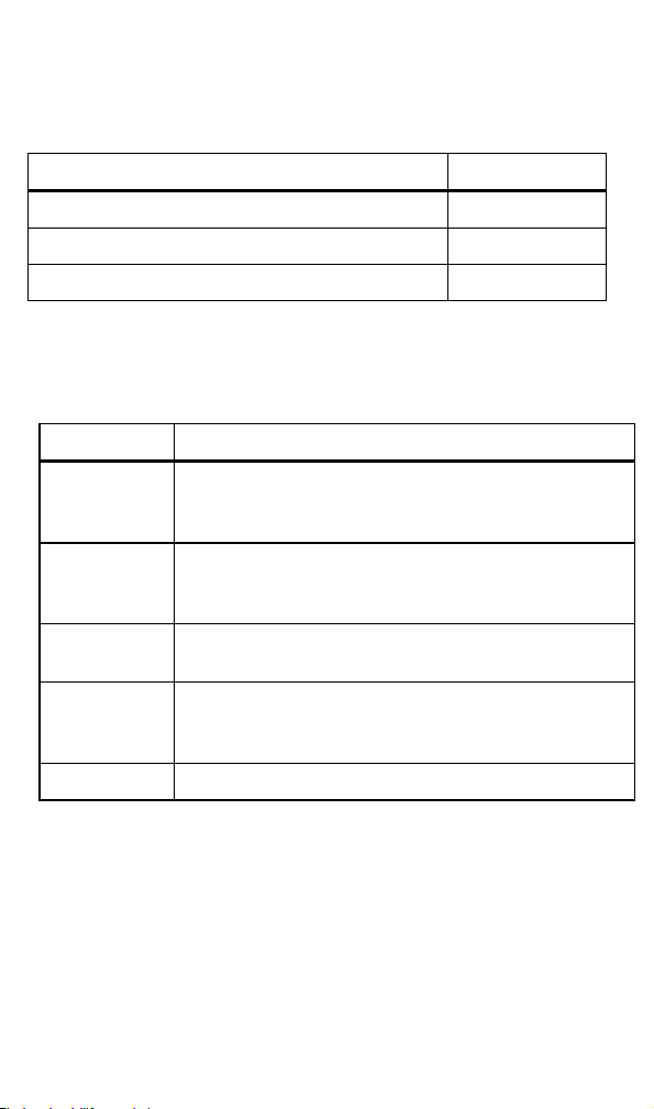
Optional Accessories
Accessories are available for the T+/T+ PRO Electrical Tester.
See Table 2.
Table 2. Accessories
Item Item Number
Belt Holster H3
Replaceable Test Probes (1 red and 1 black) TP2
Replaceable Test Lead assembly without probes 2792344
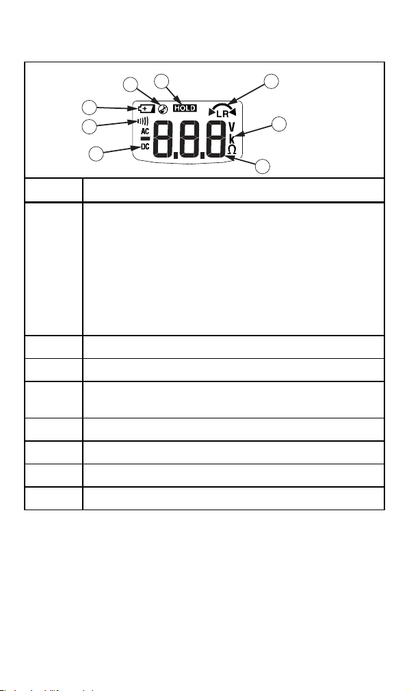
Pushbuttons
Use the pushbuttons to toggle switchable functions of the Tester
on or off. The pushbuttons are shown and described in Table 3.
Table 3. Pushbuttons
Pushbutton Description
C
O
H
Z
G Performs Ground Fault and trips the GFCI.
Press to turn the flashlight on, release to turn it off.
The flashlight will turn off 5 seconds after release of the
pushbutton. Batteries are required for this feature.
Toggles the ohms function on or off. T+PRO only. See
“Measuring Resistance (T+ PRO Only)”.
Batteries are required for this feature.
Toggles the HOLD function on or off. T+PRO only. See
“HOLD”. Batteries are required for this feature.
Turns beeper on or off. When the beeper is turned off, it
will not sound until it is reactivated. Batteries are
required for this feature.
Page 6
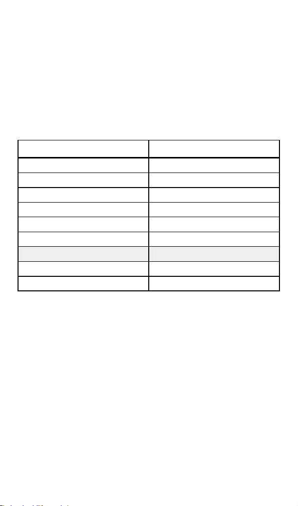
Understanding the Display (T+ PRO Only)
Display indicators are shown and described in Figure 1.
3 4
2
1
8
5
7
6
eqc001f.emf
Item Description
Low battery icon. If the battery is depleted the voltage will
still be displayed by the LED stack but the beeper and
vibration will not operate, continuity and resistance
measurements cannot be made, and the LCD will not
A
switch on.
WCaution
Replace depleted batteries immediately to avoid
damage to the Tester from battery acid leakage.
B All audible signals are disabled
C HOLD function is selected
D
Indicates phase rotation for a right or left-hand turning field
from one phase to the next in a three-phase system
E Measurement units
F Numeric display
G AC or dc volts
H Continuity test function is selected
Figure 1. Display Indicators
Page 7

Beeper
When the Tester detects a voltage, the LEDs light to indicate the
voltage level, the Tester vibrates, and a beeper sounds (the T+
PRO also shows the voltage on the display). The beeper tones are
different depending on what is being measured:
• AC voltage - the beeper is a chirping tone
• DC voltage - the beeper is a steady tone
• Continuity - the beeper is a steady tone for resistances less
than 20 kΩ
Note
If any voltage is present, the Tester automatically
switches to voltage mode.
To turn the beeper on or off, press Z for more than 3 seconds.
Each time the beeper is activated or deactivated, the Tester emits
3 short beeps.
Batteries are required for this feature.
Vibration Voltage Indication
The Tester vibrates when voltages 40 V and higher are measured.
Batteries are required for vibration to function.
Automatic Operation
The Tester automatically turns on when the probes are placed
across a complete circuit. The Tester selects continuity, ac or dc
voltage modes based on the resistance or voltage between the
probes. The tester switches off immediately after the test probes
are removed from the circuit under test or after 5 seconds if C is
released when the probes are not attached to a test circuit. If the
HOLD function is activated, this switches off after 1 minute if a
voltage is not detected.
HOLD
Press H to freeze the display reading. Press again to release
HOLD. HOLD does not interfere with the voltage LED function.
Page 8
Removing the Probe Tips
To remove the probe tips:
1. Grasp the probe firmly in one hand.
2. Hold the test lead jack firmly in the other hand.
3.
Pull to disengage the test lead probe from the test lead jack.
LED Display Voltages
Table 4 shows the differences in the displayed voltages on the
LEDs on the Canadian and USA versions of the Tester.
Table 4. LED Display Voltages
USA Canada
Q Q
R R
S S
T T
U U
V V
W
X X
Y Y
Self Test
XWWarning
To avoid possible electric shock or personal injury:
• Perform a self test before any measurements are
taken for voltage, continuity, resistance, or rotary
field.
• When the batteries are depleted, self test will not
function. Replace the batteries.
WCaution
Although the Tester may be used with depleted batteries,
replace depleted batteries immediately to avoid Tester
damage from battery acid leakage.
To perform the self test, short the two probes. The self test lights
all LEDs, and all LCD segments (T+ PRO). The beeper sounds
(unless disabled) and the Tester switches to continuity mode. The
self test will then be de-activated for 30 seconds. If the self test
needs to be repeated, wait 30 seconds.
Page 9
To complete the check procedure, always measure a known
voltage before use. If the Tester fails self test or voltage check, it
must not be used and requires service. See “Contacting Fluke”.
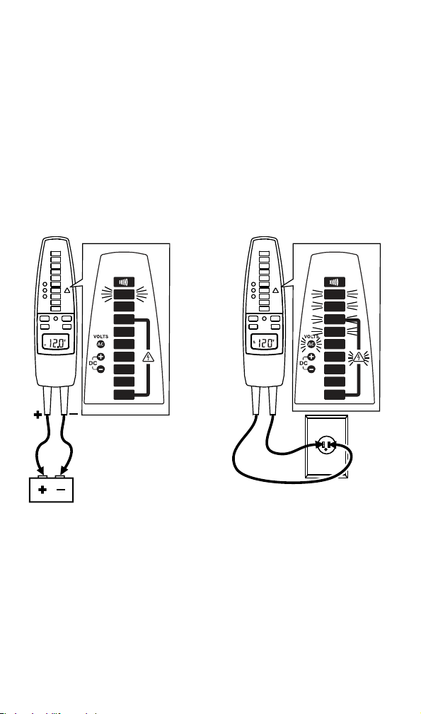
Measuring Voltage
To measure voltage, connect the probes to the circuit under test.
The voltage is indicated by the voltage LED stack and beeper (if
enabled). The T+PRO will show the measurement on the LCD for
voltages > 10 V; < 10 V the LCD remains blank. The AC, DC+ and
DC- LEDs will only operate for voltages greater than 24 V. Refer
to Figure 2.
DC Voltage
600 V dc maximum
AC Voltage
600 V rms maximum
45 Hz to 66 Hz
CONTINUITY
12
24
48
120
208
240
277
480
600
12 V dc
Figure 2. Measuring Voltage
CONTINUITY
12
24
48
120
208
240
277
480
600
120 V ac
Note
Maximum measurable voltage is 600 V ac or dc. This will
be indicated on the LED and LCD (T+ PRO).
eqc03f.eps
Page 10
Testing for Continuity
XW Warning
To avoid electrical shock:
• Make sure the power to the circuit is turned off and
all capacitors are discharged.
• If the beeper is disabled, the Tester will not beep and
only P will light. On the T+ PRO, the display will
also show F.
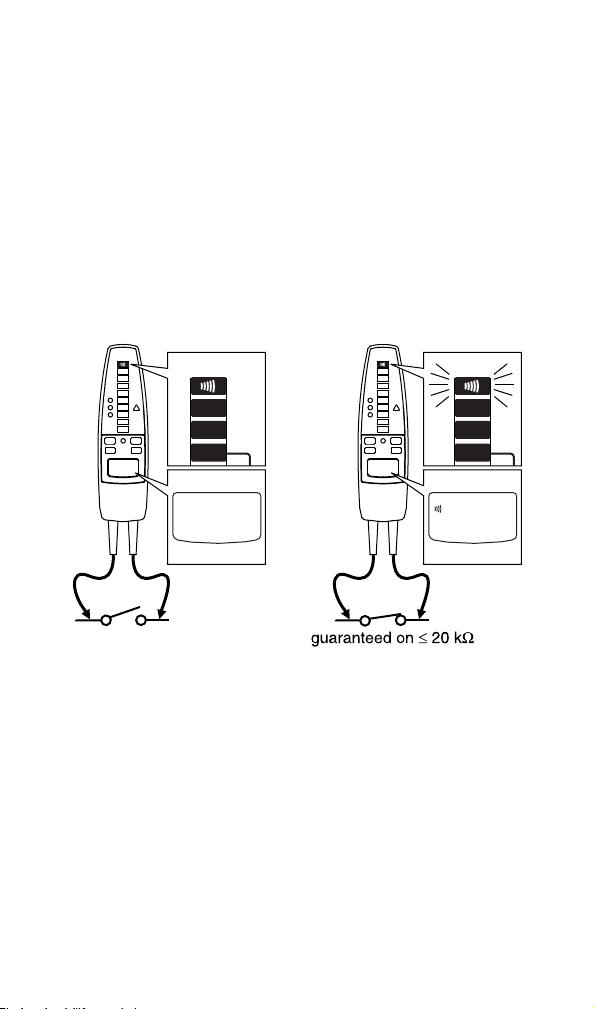
To measure continuity, turn off circuit power and connect the
probes to the circuit under test. Continuity (a resistance less than
20 kΩ) is indicated by the beeper and a lighted P. If the beeper
is disabled, it will not sound during this test. The T+PRO shows F
on the LCD. If the resistance is greater than 20 kΩ, the beeper will
not sound and P will not light. Refer to Figure 3.
CONTINUITY
open
CONTINUITY
12
24
48
Figure 3. Continuity Test
CONTINUITY
CONTINUITY
12
24
48
eqc02f.emf
Page 11
Measuring Resistance (T+ PRO Only)
XWWarning
To avoid electrical shock when measuring resistance
in a circuit, make sure the power to the circuit is
turned off and all capacitors are discharged.
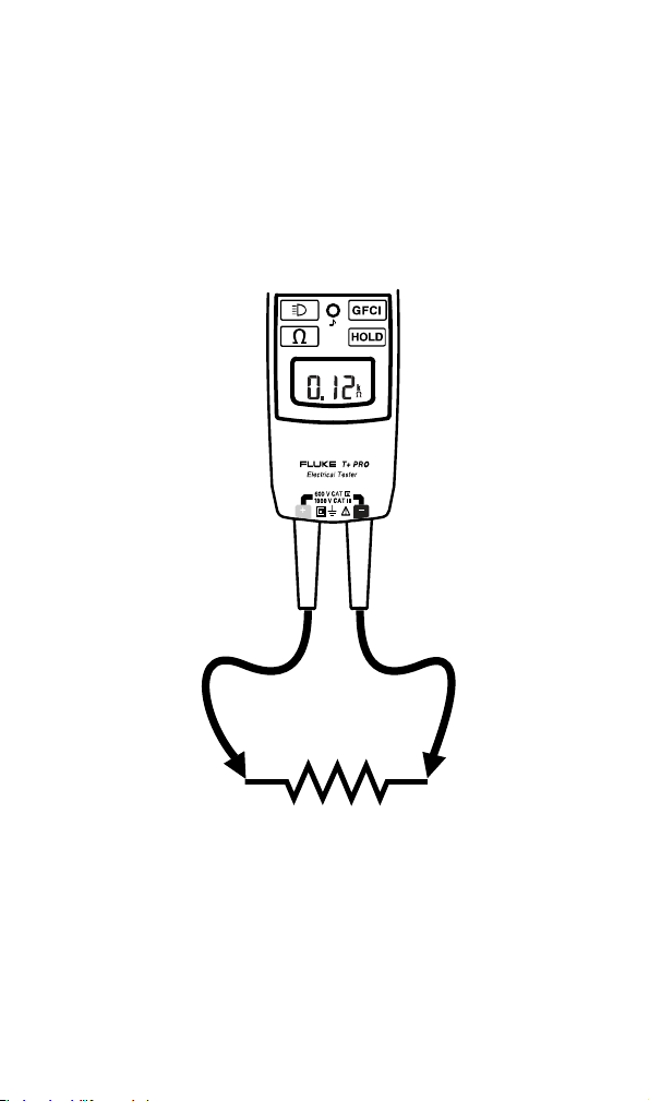
To measure resistance, turn off the circuit power, press O, and
place the test probes across the resistance under test. For
resistances less than 9.99 kΩ, the T+PRO display shows the
resistance value. For greater resistances, the display shows OL.
See Figure 4.
DISPLAY ON >10V
Figure 4. Measuring Resistance
eqc04f.eps
Page 12

GFCI Test
XWWarning
To avoid electrical shock, do not touch any exposed
metalwork during the test.
This test will switch off the power to the circuit.
To test a GFCI receptacle, do the following:
1. Insert the Tester probes into the GFCI receptacle under test.
2. Connect probes to the phase (hot) and ground (PE-protective
earth) of the GFCI receptacle.
3. Press Gfor 1 second. The DC+ and DC- LEDs will
alternately switch on and off and, if activated, the beeper will
sound indicating that a test is in progress. The test may last
up to 7 seconds.
4. Keep the probes connected while the LEDs are switching on
and off. If the GFCI trips, power to the circuit will be
interrupted and the Tester will stop indicating voltage. If the
GFCI does not trip after approximately 7 seconds, the GFCI
test stops, indicated by no switching of the DC+ and DCLEDs but the tester will continue to indicate the presence of
voltage.
When testing and verifying GFCI circuits or components, do the
following:
• Consult the GFCI manufacturer’s installation instructions to
determine that the GFCI is installed in accordance with its
specifications.
• Check for correct wiring of receptacles and all remotelyconnected receptacles on branch circuits.
• Operate the pushbutton on the GFCI receptacle installed in
the circuit. The GFCI must trip. If it does not, the GFCI
receptacle is not operating properly. DO NOT use the circuit.
Consult an electrician or properly certified personnel.
If the GFCI does trip, retest the receptacle as explained
above.
If the Tester fails to trip the GFCI, consider either of the following:
• The GFCI is fully functional but a wiring problem exists within
the installation or receptacle.
• The GFCI is faulty and the installation wiring is correct.
Consult an electrician to check the wiring and GFCI.
Note
• After a GFCI test, further GFCI tests will be inhibited for 0.5
seconds.
Page 13

• It is not possible to switch the beeper off during a GFCI
test.
XWWarning
To avoid possible electric shock or personal injury,
follow these guidelines:
• When testing GFCIs installed in 2-wire systems,
(systems where no ground wire is available at
the receptacle) the Tester may give a false
indication that the GFCI is not functioning
properly. If this occurs, recheck the operation of
the GFCI using the test and reset button.
• The GFCI button test function should
demonstrate proper operations. However, if there
is cause to verify proper operation of the GFCI
receptacle in a 2-wire system, apply one test
probe of the Tester to the energized input of the
GFCI receptacle while applying the alternates
test probe to a known external neutral or ground
reference location external to the GFCI
receptacle. Operate the GFCI button on the
Tester as described in the Instruction Sheet to
verify the GFCI receptacle is operating properly.
Rotary Field Direction (T+ PRO Only)
This test shows the direction of a rotary field in a three-phase
system when measured phase to phase. The LCD indicates phase
rotation for a right or left-hand turning field from one phase to the
next in a three-phase system.
Note
If measuring from phase to neutral at a panel or singlephase outlet, the Tester may indicate Jor K.
However, this is not a valid reading. A valid reading can
only come from a phase to phase circuit. The rotary field
function is specified for use on line (mains) systems only.
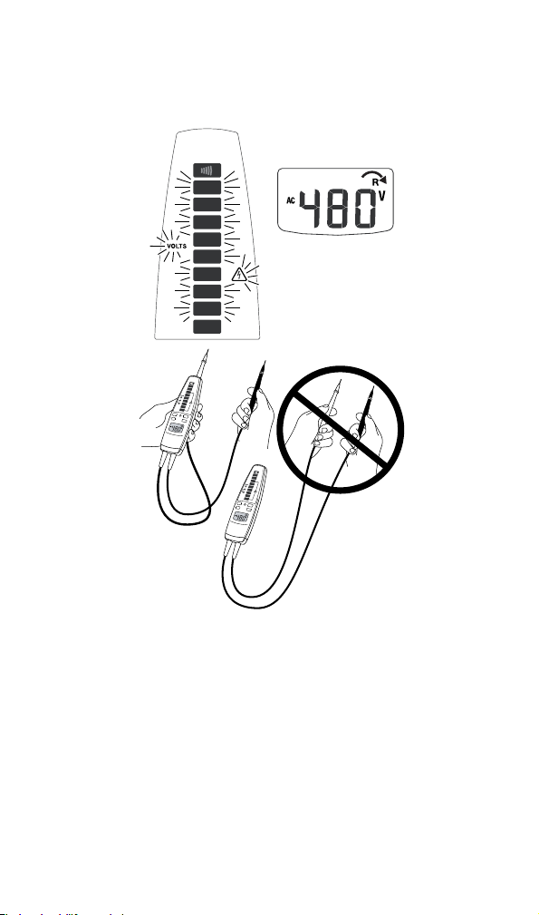
To perform a rotary field direction test, see Figure 5:
1. Attach one probe to the center probe holder on the back of
the Tester and grip the main body with one hand.
2. Attach both probes to the test points. If the red lead is 120
degrees ahead of the black lead, K is displayed. If the red
lead lags the black lead by 120 degrees, J is displayed. In
both situations the voltage is shown on the display. If a phase
rotation measurement is not possible, no arrows will light but
the voltage appears on the display.
Page 14
Note
You can verify the rotary field direction by reversing the
two probes and watching for an indication of a change in
the field direction.
CONTINUITY
12
24
48
120
208
240
277
480
600
CONT
INU
ITY
12
24
48
120
208
240
277
480
600
CONT
INU
ITY
12
24
48
120
208
240
277
480
600
Figure 5. Rotary Field Measurement
eqc05f.emf
Page 15

Maintenance
WCaution
Do not use abrasives or solvents on the Tester.
Clean the case with a damp cloth and mild detergent.
Replacing the Batteries
Perform a self test to determine the charge state of the batteries
on T+ Testers. The self test will not work with dead batteries. On
T+ PRO Testers, the low battery icon (B) on the LCD indicates
that the batteries need to be replaced.
XWWarning
To avoid possible electric shock or personal injury:
• Disconnect test leads from any electrical source
before opening the battery compartment.
• Do not operate the Tester with the battery door or
portions of the cover removed or loosened.
1. Turn the Tester over and use a flat-head screwdriver to
loosen the battery door screw and remove the door.
2. Replace the batteries with two new AAA alkaline batteries.
3. Reattach the battery compartment door and reinstall the
screw.
Specifications
Temperature: Operating: -10 °C to 55 °C (14 °F to 131 °F)
Relative Humidity: 0 °C to 30 °C (32 °F to 86 °F) 90 %
Altitude: Operating: 2,000 m
Battery Type/Life: AAA (2); 40 hours
Shock, Vibration: Sinusoidal vibration per MIL-PRF-28800F for a
Safety: ANSI/ISA S82.02.01, CSA C22.2-1010.1, IEC 61010-1
AC Bandwidth:
Maximum Input
Voltage Between
Terminal and
Earth Ground:
Duty Cycle: Indefinitely for voltages up to 240 V.
Storage: -30 °C to +60 °C (-22 °F to +140 °F)
30 °C to 40 °C (86 °F to 104 °F) 75 %
40 °C to 50 °C (104 °F to 122 °F): 45 %
Storage: 10,000 m
Class 2 instrument
to 1000 V CAT III/600 V CAT IV; Pollution Degree II
45 Hz to 66 Hz
Maximum working voltage 1000 V ac or dc.
Maximum measurable voltage 600 V ac or dc. This will
be displayed on the LED and the LCD (T+ PRO).
v
oltages between 240 V to 600 V the duty cycle is
For
30 seconds on / 300 seconds off. For voltages above
240 V the Tester must connect to a voltage source
Page 16

only for a MAXIMUM of 30 seconds and then
Voltage
Hazard LED: LEDs turn on @ voltages > 30 V ac/dc ± 35 %
LEDs turn on @ between 70 % and 100 % of the
LEDs:
EMC Compliance: EN61326-1:2005 Class B emissions and immunity in
Accuracy:
AC voltage: ± (3 % rdg. + 2 digits)
DC voltage: ± (2 % rdg + 2 digits)
Resistance: ± (5 % rdg + 3 digits)
LCD Resolution: 0.1 V for voltages < 50 V, 1 V for voltages ≥ 50 V,
GFCI Test
Current: 100 V - 150 V @ 6 mA - 9 mA ac
Standard Input
Test Current: < 5 mA
Size (HxWxL): 1.3 in x 2.15 in x 7.6 in
Weight: 9.9 oz
This Fluke product will be free from defects in material and workmanship
for two years from the date of purchase. This warranty does not cover
fuses, disposable batteries, or damage from accident, neglect, misuse,
alteration, contamination, or abnormal conditions of operation or handling.
Resellers are not authorized to extend any other warranty on Fluke’s
behalf. To obtain service during the warranty period, contact your nearest
Fluke authorized service center to obtain return authorization information,
then send your defective Tester to that Service Center with a description of
the problem. Replace depleted batteries immediately to avoid Tester
damage from battery leakage.
THIS WARRANTY IS YOUR ONLY REMEDY. NO OTHER
WARRANTIES, SUCH AS FITNESS FOR A PARTICULAR PURPOSE,
ARE EXPRESSED OR IMPLIED. FLUKE IS NOT LIABLE FOR ANY
SPECIAL, INDIRECT, INCIDENTAL OR CONSEQUENTIAL DAMAGES
OR LOSSES, ARISING FROM ANY CAUSE OR THEORY. Since some
states or countries do not allow the exclusion or limitation of an implied
warranty or of incidental or consequential damages, this limitation of
liability may not apply to you.
disconnect for a MINIMUM of 300 seconds.
indicated voltage on the LED, except for the 12 V LED
which turns on @ between 50 % and 100 %.
field strengths between 1 V/m and 3 V/m add
8 % of range.
0.01 kΩ at resistance measurement
150 V – 240 V < 12 mA
LIMITED WARRANTY & LIMITATION OF LIABILITY
11/99
99 Washington Street
Melrose, MA 02176
800.517.8431
TestEquipmentDepot.com
 Loading...