

Page 1

Manual Supplement
Manual Title: 8920A/8921A Supplement Issue: 8
Part Number: 487157 Issue Date: 6/99
Print Date: October 1978 Page Count: 4
Revision/Date:
This supplement contains information necessary to ensure the accuracy of
the above manual. Enter the corrections in the manual if either one of the
following conditions exist:
1. The revision letter stamped on the indicated PCA is equal to or higher
than that given with each change.
2. No revision letter is indicated at the beginning of the change.
© 1999 Fluke Corporation. All rights reserved. Printed in the U.S.A.
Page 2
8920A/8921A Manual Supplement
Change #1
On page 1-4, replace everything on the page with the following:
AC + DC (add to AC specification. Assume 100 Hz if AC component is negligible.) :
Accuracy:
Above 2 mV +/-(10 digits or 0.5 dB)
Below 2 mV +/-(100 digits or 5 dB)
Temperature Coefficient (0 to 18 degree C/28 to 50 degree C):
Above 2 mV +/-(2 digits/degree C or 0.1 dB/degree C)
Below 2 mV +/-(20 digits/degree C or 1 dB/degree C)
Change #2
On page 4-20, replace Table 4-12 with the f ollowing:
Table 4-12. R19/R34, R66/R76 Resistive Values (mF, ±1%, 1/8W)
VALUE VALUE VALUE VALUE
499 K 34.8 K 68.1 K 24.3 K
332 K 32.4 K 57.6 K 22.6 K
169 K 30.1 K 48.7 K 21.5 K
115 K 28.0 K 43.2 K 20.5 K
86.6 K 26.1 K 38. K 19.1 K
Change #3
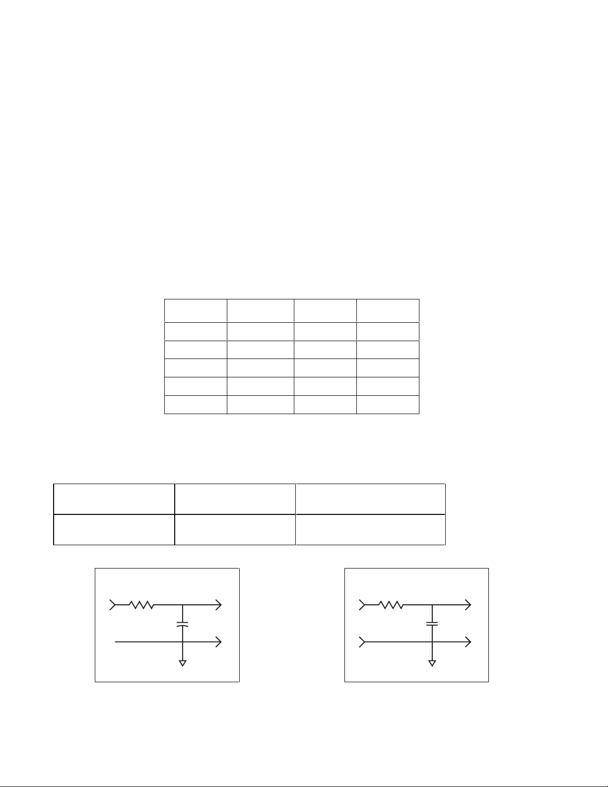
On page 4-2, add the following to the bott om of Table 4-1:
EQUIPMENT
NONMENCLATURE
Input Filter
Input Filter
500 Hz
100 W
REQUIREMENT RECOMMENDED
500 Hz
50 kHz
INPUT FILTERS
EQUIPMENT
Figure A.
Figure B.
50 Hz
100 W
.1 mf
8920_21_figa.eps
Figure A.
6/99 1
510 pf
8920_21_fig_b.eps
Figure B.
Page 3

Manual Supplement 8920A/8921A
Change #4
On page 4-14, paragraph 4-39, step 3, line 2,
Change: ...reading stops decreasing...
To: ...reading stops increasing...
Change #5
On pages 5-20 and 5-21, Table 5-5,
Change: R17|RESISTOR/DUAL FET SET|476788|89536|476788|1| |1
To: R17|RESISTOR/DUAL FET SET(WITH Q9)|476788|89536|476788|1| |1
Change: R46|RESISTOR/DUAL FET SET|476788|89536|476788|REF| |2
To: R46|RESISTOR/DUAL FET SET(WITH Q37)|476788|89536|476788|REF| |2
On page 5-23, at the end of flagnote 3, add:
Dual Fet Sets R17 and Q9, and R46 and Q37 cannot be interm ixed.
Change #6
On page 603-8, Table 603-4:
Delete: Steps 5, 6 and 7
On pages 603-6 thru 603-8:
Delete: "MEASURE BETWEEN HIGH TERMINAL - LOW TERMINAL" in all
places but the first entry under st ep 1.
Change #7
On page 604-4, change step 5 to read as follows: (the example does not change)
5. While still monitoring TP501 change the applied input to 200 mV at 500 Hz and adjust R512 for
a reading of -10V +/-OFFSET of step 4 +/-0.001V. The UUT should still be at the 200 mV range.
Change #8
On page 4-7, Table 4-5, under the UUT DI SPLAY colum n:
Change: 1.000 +/-30 counts
To: 1.000 +/-15 counts
Change: +/- 6 counts
To: +/-12 counts
Change #9
On page 1-5, add the following specification:
PROTECTION CLASS Class 1 (As defined in IEC 348. )
26/99
Page 4

8920A/8921A Manual Supplement
Change #10
On page 4-4, Table 4-3, change the first entry under INPUT LEVEL and DISPLAY,
From: 1.9 mV 1.000
To: 1.0 mV 1.900
Change #11
On page 4-5,
Change: 2-d. Note that the UUT’s display reads the same error as noted in step
1-f +/-38 digits.
2-e. Note that the UUT’s display reads 0.1900 +/-4 digits.
To: 2-d. Make no adjustments. Allow 1.000 +/-40 digits.
2-e. Allow 0.180 to 0.188 after settling.
On page 4-7, Table 4-5,
Change: UUT DISPLAY +/-6 COUNTS
To: UUT DISPLAY
Change #12
On page 4-12, Table 4-7, change step 23,
From: Increase the input to 206 mV and check.............
To: Increase the input to 25.6 mV and check............
Change #13
On page 603-1, paragraph 603-6, add new steps 4 and 5 as follows, and renumber old steps 4
and 5 as step 6 and 7.
4. Connect ground wire (P403) to J403 on the A1 Main PCB Assembly.
5. Place the rubber foot on the AC shield near the screws as shown in Figure 603-1.
6/99 3
Page 5

Manual Supplement 8920A/8921A
On page 603-2, replace Figure 603-1 with:
2
(2 PL)
(2 PL)
1
1
6
3
2
P403 (Ref)
J403
(Ref)
2
Main
Assembly
(Ref)
Change #14
On page 604-4, change step 3,
From: Apply 20.0 mV, 500 Hz to the 8920A and select its HOLD RANGE...
To: Apply 20.0 mV, 500 Hz to the 8920A and select its HOLD RANGE (200
Change #15
On page 1-5, Table 1-3, add:
Electromagnetic Compatibility
8920A: For field strengths between 2 V/m and 3 V/m , add 15 mV to all specifications.
8921A: For field strengths between 0.5 V/m and 3 V/ m , add 400 mV to all
specifications.
Figure 603-1
8922_fig603_1.eps
mV range)...
46/99
 Loading...