

Page 1

®
8845A/8846A
Digital Multimeter
Calibration Manual
January 2007
© 2007 Fluke Corporation, All rights reserved.
All product names are trademarks of their respective companies.
Page 2

LIMITED WARRANTY AND LIMITATION OF LIABILITY
Each Fluke product is warranted to be free from defects in material and workmanship under normal use and
service. The warranty period is one year and begins on the date of shipment. Parts, product repairs, and
services are warranted for 90 days. This warranty extends only to the original buyer or end-user customer of
a Fluke authorized reseller, and does not apply to fuses, disposable batteries, or to any product which, in
Fluke's opinion, has been misused, altered, neglected, contaminated, or damaged by accident or abnormal
conditions of operation or handling. Fluke warrants that software will operate substantially in accordance
with its functional specifications for 90 days and that it has been properly recorded on non-defective media.
Fluke does not warrant that software will be error free or operate without interruption.
Fluke authorized resellers shall extend this warranty on new and unused products to end-user customers
only but have no authority to extend a greater or different warranty on behalf of Fluke. Warranty support is
available only if product is purchased through a Fluke authorized sales outlet or Buyer has paid the
applicable international price. Fluke reserves the right to invoice Buyer for importation costs of
repair/replacement parts when product purchased in one country is submitted for repair in another country.
Fluke's warranty obligation is limited, at Fluke's option, to refund of the purchase price, free of charge repair,
or replacement of a defective product which is returned to a Fluke authorized service center within the
warranty period.
To obtain warranty service, contact your nearest Fluke authorized service center to obtain return
authorization information, then send the product to that service center, with a description of the difficulty,
postage and insurance prepaid (FOB Destination). Fluke assumes no risk for damage in transit. Following
warranty repair, the product will be returned to Buyer, transportation prepaid (FOB Destination). If Fluke
determines that failure was caused by neglect, misuse, contamination, alteration, accident, or abnormal
condition of operation or handling, including overvoltage failures caused by use outside the product’s
specified rating, or normal wear and tear of mechanical components, Fluke will provide an estimate of repair
costs and obtain authorization before commencing the work. Following repair, the product will be returned to
the Buyer transportation prepaid and the Buyer will be billed for the repair and return transportation charges
(FOB Shipping Point).
THIS WARRANTY IS BUYER'S SOLE AND EXCLUSIVE REMEDY AND IS IN LIEU OF ALL OTHER
WARRANTIES, EXPRESS OR IMPLIED, INCLUDING BUT NOT LIMITED TO ANY IMPLIED WARRANTY
OF MERCHANTABILITY OR FITNESS FOR A PARTICULAR PURPOSE. FLUKE SHALL NOT BE LIABLE
FOR ANY SPECIAL, INDIRECT, INCIDENTAL, OR CONSEQUENTIAL DAMAGES OR LOSSES,
INCLUDING LOSS OF DATA, ARISING FROM ANY CAUSE OR THEORY.
Since some countries or states do not allow limitation of the term of an implied warranty, or exclusion or
limitation of incidental or consequential damages, the limitations and exclusions of this warranty may not
apply to every buyer. If any provision of this Warranty is held invalid or unenforceable by a court or other
decision-maker of competent jurisdiction, such holding will not affect the validity or enforceability of any other
provision.
Fluke Corporation
P.O. Box 9090
Everett, WA 98206-9090
U.S.A.
Fluke Europe B.V.
P.O. Box 1186
5602 BD Eindhoven
The Netherlands
11/99
To register your product online, visit register.fluke.com
Page 3

Table of Contents
Chapter Title Page
1 Introduction and Specifications......................................................... 1-1
Introduction........................................................................................................ 1-3
Safety Information ............................................................................................. 1-3
Symbols ......................................................................................................... 1-4
General Safety Summary............................................................................... 1-4
Description of IEC 61010 Measurement Categories ......................................... 1-6
Organization of the Calibration Manual ............................................................ 1-7
Chapter 1 – Introduction and Specifications ................................................. 1-7
Chapter 2 – General Maintenance ................................................................. 1-7
Chapter 3 – Performance Test and Calibration.............................................. 1-7
Chapter 4 – List of Replaceable Parts ........................................................... 1-7
Operating Instructions........................................................................................ 1-7
Accessories ........................................................................................................ 1-7
General Specifications ....................................................................................... 1-9
Power............................................................................................................. 1-9
Dimensions.................................................................................................... 1-9
Display........................................................................................................... 1-9
Environment .................................................................................................. 1-9
Safety............................................................................................................. 1-9
EMC .............................................................................................................. 1-9
Triggering...................................................................................................... 1-9
Memory ......................................................................................................... 1-10
Math Functions.............................................................................................. 1-10
Electrical........................................................................................................ 1-10
Remote Interfaces.......................................................................................... 1-10
Warranty........................................................................................................ 1-10
Electrical Specifications .................................................................................... 1-10
DC Voltage Specifications ............................................................................ 1-10
Input Characteristics.................................................................................. 1-10
8846A Accuracy........................................................................................ 1-11
8845A Accuracy........................................................................................ 1-11
Additional Errors....................................................................................... 1-11
AC Voltage Specifications ............................................................................ 1-11
Input Characteristics.................................................................................. 1-12
8846A Accuracy........................................................................................ 1-12
i
Page 4

8845A/8846A
Calibration Manual
8845A Accuracy........................................................................................ 1-13
Additional Low Frequency Errors............................................................. 1-13
Resistance...................................................................................................... 1-14
Input Characteristics.................................................................................. 1-14
8846A Accuracy........................................................................................ 1-14
8845A Accuracy........................................................................................ 1-14
Additional Ohms Errors ............................................................................ 1-15
DC Current .................................................................................................... 1-15
Input Characteristics.................................................................................. 1-15
Accuracy (8846A)..................................................................................... 1-15
Accuracy (8845A)..................................................................................... 1-16
Additional Current Errors ......................................................................... 1-16
AC Current .................................................................................................... 1-16
Input Characteristics.................................................................................. 1-16
8846A Accuracy........................................................................................ 1-17
8845A Accuracy........................................................................................ 1-18
Additional Low Frequency Errors............................................................. 1-18
Frequency ...................................................................................................... 1-18
8846A Accuracy........................................................................................ 1-19
8845A Accuracy........................................................................................ 1-19
Gate Time vs. Resolution.......................................................................... 1-19
Additional Low Frequency Errors............................................................. 1-20
Capacitance (8846A Only) ............................................................................ 1-20
Temperature (8846A only) ............................................................................ 1-20
Continuity...................................................................................................... 1-20
Diode Test ..................................................................................................... 1-21
Measurement Rates ....................................................................................... 1-21
Measurement Uncertainty.................................................................................. 1-21
Interpreting Accuracy Specifications................................................................. 1-22
24-Hour Accuracy ......................................................................................... 1-22
90-Day and 1-Year Accuracy ........................................................................ 1-22
Temperature Coefficients .............................................................................. 1-22
Configuring for Highest Accuracy Measurements ............................................ 1-22
DC Voltage, DC Current, and Resistance Measurements ............................. 1-22
AC Voltage and AC Current Measurements: ................................................ 1-22
Frequency and Period Measurements:........................................................... 1-22
2 General Maintenance .......................................................................... 2-1
Introduction........................................................................................................ 2-3
Warranty Repairs and Shipping Information..................................................... 2-3
General Maintenance Information ..................................................................... 2-3
Required Equipment...................................................................................... 2-3
Power Requirements...................................................................................... 2-3
Static Safe Handling ...................................................................................... 2-3
Cleaning............................................................................................................. 2-4
Fuse Replacement .............................................................................................. 2-4
Line-Power Fuse............................................................................................ 2-4
Current-Input Fuses ....................................................................................... 2-5
If the Meter Does Not Turn On.......................................................................... 2-7
Display Tests...................................................................................................... 2-7
Disassembly Procedures .................................................................................... 2-7
General Disassembly ..................................................................................... 2-7
Main Chassis Disassembly ............................................................................ 2-8
Front Panel Disassembly ............................................................................... 2-8
ii
Page 5

Contents (continued)
Assembly Procedures......................................................................................... 2-8
3 Performance Test and Calibration..................................................... 3-1
Introduction........................................................................................................ 3-3
Required Equipment .......................................................................................... 3-3
Test Considerations............................................................................................ 3-5
Performance Tests.............................................................................................. 3-5
Volts DC Verification.................................................................................... 3-5
Volts AC and Frequency Verification ........................................................... 3-8
4-Wire Ohms Verification............................................................................. 3-12
2-Wire Ohms Verification............................................................................. 3-14
2X4 Test Lead Verification Steps ................................................................. 3-16
Rear Panel Terminal Verification Steps ........................................................ 3-16
Capacitance Verification Steps (8846A only) ............................................... 3-18
DC Current Verification Steps ...................................................................... 3-19
AC Current Verification Steps ...................................................................... 3-22
Adjustment (Calibration) ................................................................................... 3-24
Unlocking the Meter for Front-Panel Adjustments (Calibration).................. 3-24
Unlocking the Meter for Adjustments Over a Remote Interface................... 3-25
Changing the Calibration Password .............................................................. 3-25
Resetting the Calibration Password............................................................... 3-25
Equipment for Calibration............................................................................. 3-26
Adjustment Process ....................................................................................... 3-26
Aborting a Calibration Process...................................................................... 3-32
Sample Adjustment Program......................................................................... 3-32
4 List of Replaceable Parts.................................................................... 4-1
Introduction........................................................................................................ 4-3
How to Obtain Parts........................................................................................... 4-3
How to Contact Fluke ........................................................................................ 4-3
Parts ................................................................................................................... 4-4
Appendices
A Verification Forms ...................................................................................... A-1
B Example Adjustment Program .................................................................... B-1
iii
Page 6

8845A/8846A
Calibration Manual
iv
Page 7

List of Tables
Table Title Page
1-1. Safety and Electrical Symbols................................................................................ 1-4
1-2. Safety Information ................................................................................................. 1-5
1-3. Accessories............................................................................................................. 1-7
2-1. Line Voltage to Fuse Rating................................................................................... 2-5
3-1. Required Test Equipment....................................................................................... 3-3
3-2. 8846A DC Volts Verification Steps....................................................................... 3-6
3-3. 8845A DC Volts Verification Steps....................................................................... 3-7
3-4. 8846A AC Volts Verification Steps....................................................................... 3-9
3-5. 8845A AC Volts Verification Steps....................................................................... 3-10
3-6. 8845A/8846A AC Volts Frequency Verification Steps ......................................... 3-11
3-7. 8846A 4-Wire Ohms Verification Steps ................................................................ 3-13
3-8. 8845A 4-Wire Ohms Verification Steps ................................................................ 3-13
3-9. 8846A 2-Wire Ohms Verification Steps ................................................................ 3-15
3-10. 8845A 2-Wire Ohms Verification Steps ................................................................ 3-15
3-11. 8846A Rear-Panel Terminal Verification Steps (Optional Test) ........................... 3-18
3-12. 8845A Rear-Panel Terminal Verification Steps (Optional Test) ........................... 3-18
3-13. 8846A Capacitance Verification Steps .................................................................. 3-18
3-14. 8846A DC Current Verification Steps ................................................................... 3-19
3-15. 8845A DC Current Verifications Steps.................................................................. 3-20
3-17. 8845A AC Current Verification Steps ................................................................... 3-23
3-18. 8845A/8846A Adjustment Steps............................................................................ 3-27
4-1. Replaceable Parts ................................................................................................... 4-4
A-1. Blank Verification Record for 90-Day Specifications ........................................... A-2
A-2. Blank Verification Record for 1-Year Specifications............................................ A-9
v
Page 8

8845A/8846A
Calibration Manual
vi
Page 9

List of Figures
Figure Title Page
1-1. IEC 61010 Measurement Category (CAT) Levels................................................. 1-6
2-1. Line Fuse Replacement .......................................................................................... 2-5
2-2. Current Input Fuse Replacement............................................................................ 2-6
3-1. DC Volts Test Equipment Setup with 5520A ........................................................ 3-6
3-2. AC Volts Test Equipment Setup with 5520A ........................................................ 3-8
3-3. 4-Wire Ohms Test Equipment Setup ..................................................................... 3-12
3-4. 2-Wire Ohms Test Equipment Setup ..................................................................... 3-14
3-5. Rear-Panel Terminals Equipment Setup ................................................................ 3-17
3-6. Capacitance Equipment Setup................................................................................ 3-18
3-7. DC Current Equipment Setup ................................................................................ 3-19
3-8. AC Current Equipment Setup ................................................................................ 3-22
3-9. Calibration Jumper Location.................................................................................. 3-26
4-1. Final Assembly....................................................................................................... 4-7
vii
Page 10

8845A/8846A
Calibration Manual
viii
Page 11

Chapter 1
Introduction and Specifications
Title Page
Introduction........................................................................................................ 1-3
Safety Information ............................................................................................. 1-3
Symbols ......................................................................................................... 1-4
General Safety Summary............................................................................... 1-4
Description of IEC 61010 Measurement Categories ......................................... 1-6
Organization of the Calibration Manual ............................................................ 1-7
Chapter 1 – Introduction and Specifications ................................................. 1-7
Chapter 2 – General Maintenance ................................................................. 1-7
Chapter 3 – Performance Test and Calibration.............................................. 1-7
Chapter 4 – List of Replaceable Parts ........................................................... 1-7
Operating Instructions........................................................................................ 1-7
Accessories ........................................................................................................ 1-7
General Specifications ....................................................................................... 1-9
Power............................................................................................................. 1-9
Dimensions.................................................................................................... 1-9
Display........................................................................................................... 1-9
Environment .................................................................................................. 1-9
Safety............................................................................................................. 1-9
EMC .............................................................................................................. 1-9
Triggering...................................................................................................... 1-9
Memory ......................................................................................................... 1-10
Math Functions.............................................................................................. 1-10
Electrical........................................................................................................ 1-10
Remote Interfaces.......................................................................................... 1-10
Warranty........................................................................................................ 1-10
Electrical Specifications .................................................................................... 1-10
DC Voltage Specifications ............................................................................ 1-10
AC Voltage Specifications ............................................................................ 1-11
Resistance...................................................................................................... 1-14
DC Current .................................................................................................... 1-15
AC Current .................................................................................................... 1-16
Frequency ...................................................................................................... 1-18
Capacitance (8846A Only) ............................................................................ 1-20
Temperature (8846A only) ............................................................................ 1-20
Continuity...................................................................................................... 1-20
1-1
Page 12

8845A/8846A
Calibration Manual
Diode Test ..................................................................................................... 1-21
Measurement Rates ....................................................................................... 1-21
Measurement Uncertainty.................................................................................. 1-21
Interpreting Accuracy Specifications................................................................. 1-22
24-Hour Accuracy ......................................................................................... 1-22
90-Day and 1-Year Accuracy ........................................................................ 1-22
Temperature Coefficients .............................................................................. 1-22
Configuring for Highest Accuracy Measurements ............................................ 1-22
DC Voltage, DC Current, and Resistance Measurements ............................. 1-22
AC Voltage and AC Current Measurements: ................................................ 1-22
Frequency and Period Measurements:........................................................... 1-22
1-2
Page 13

Introduction and Specifications
Introduction 1
Introduction
The 8845A and 8846A are 6-1/2 digit, dual-display multimeters designed for bench-top,
field service, and system applications. Their full complement of measurement functions
plus its RS-232, IEEE 488, and Ethernet Remote Interfaces makes these multimeters
ideal candidates for precision manual measurements and use in automated systems. For
portability, these multimeters include a carrying handle that also serves as a bail for
bench top operation.
There are a few additional features in the 8846A that are not present in the 8845A. These
features will be identified with the annotation of “8846A Only” by each feature that is
found only in that model. Separate specification tables are also used to clarify the
differences between these two models.
The following is a list of some of the features and functions:
• Bright, large-digit, wide-viewing-angle display
• Dual display for displaying two properties of an input signal (e.g., ac voltage in one
display and frequency in the other).
• Remote operation via IEEE 488, RS-232, and Ethernet interface.
• Trigger in and measurement-complete out
• Front panel USB port for optional memory (8846A Only)
• 6-1/2 digit resolution
• Half-rack width
• True rms ac
• 2 and 4-wire resistance measurements
• Extended 10 Ω and 1 GΩ ranges (8846A Only)
• Frequency measurements to 300 kHz (8846A to 1 MHz)
• Capacitance measurements (8846A Only)
• Temperature measurement (8846A Only)
• 10 A current capability
• Decibels (dB and dBm) with variable reference impedance and audio power
measurement capability
• Input terminals on both front and rear panels of the meter
• Closed-case calibration (no internal calibration adjustments)
This calibration manual focuses on performance verification and calibration of the Fluke
8845A and 8846A Digital Multimeters (hereafter referred to as the Meter).
Safety Information
This section addresses safety considerations and describes symbols that may appear on
the Meter or in the manual.
A Warning statement identifies conditions or practices that could result in injury or
death.
A Caution statement identifies conditions or practices that could result in damage to the
Meter or equipment to which it is connected.
1-3
Page 14
8845A/8846A
Calibration Manual
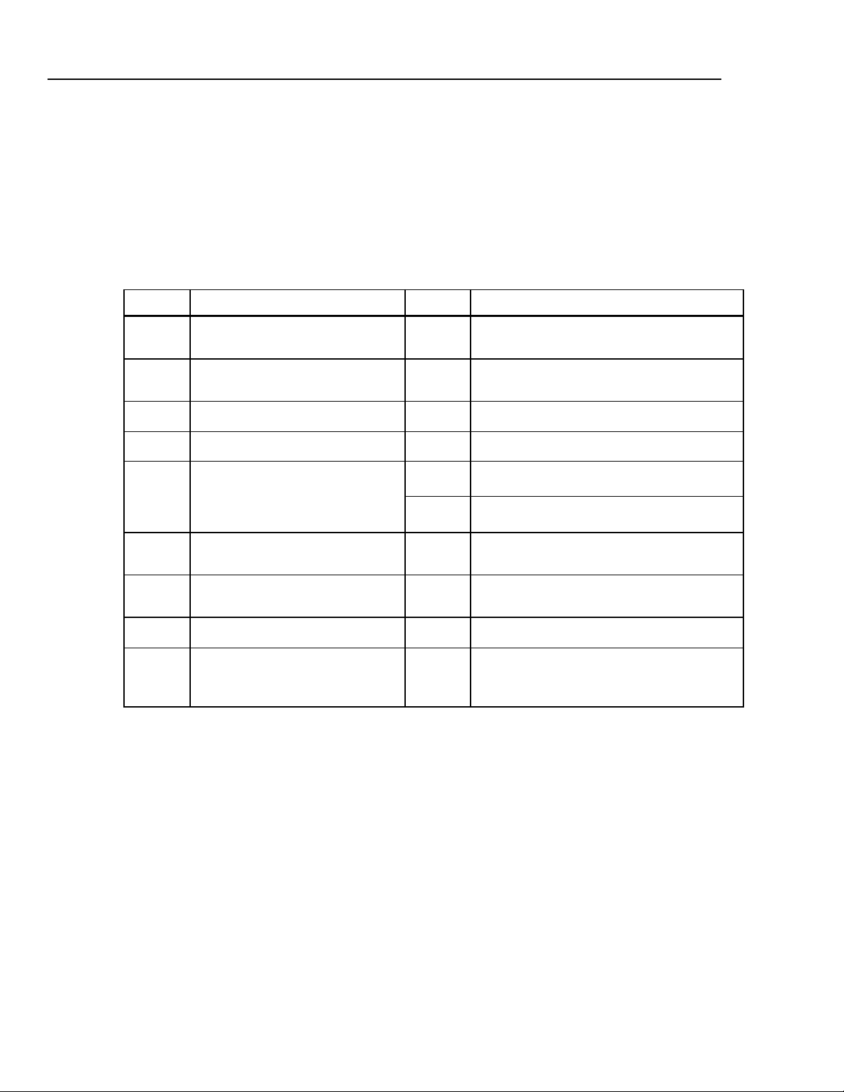
Symbols
Symbol Description Symbol Description
XW Warning
To avoid electric shock, personal injury, or death, carefully read
the information under “Safety Information” before attempting to
install, use, or service the Meter.
Table 1-1 is a list of safety and electrical symbols that appear on the Meter or in this
manual.
Table 1-1. Safety and Electrical Symbols
W
X
B
F
D
or
C
R
Y
T
h
Risk of danger. Important
information. See manual
Hazardous voltage. Voltage > 30 V
dc or ac peak might be present
AC (Alternating Current)
DC (Direct Current)
AC or DC (Alternating or Direct
Current)
Continuity test or continuity beeper
tone
Potentially hazardous voltage
Double insulated
Static awareness. Static discharge
can damage part(s)
O
J
E
G
I
Y
U
CAT II
<
~
Display ON / OFF
Earth ground
Capacitance
Diode
Fuse
Digital signal
Maintenance or Service
IEC 61010 Overvoltage (installation or
measurement) Category 2.
Recycle
Do not dispose of this product as unsorted
municipal waste. Contact Fluke or a qualified
recycler for disposal
1-4
General Safety Summary
This instrument has been designed and tested in accordance with the European standard
publication EN 61010-1:2001 and U.S. / Canadian standard publications UL 61010-1A1
and CAN/CSA-C22.2 No.61010.1. The Meter has been supplied in a safe condition.
This manual contains information and warnings that must be observed to keep the
instrument in a safe condition and ensure safe operation.
To use the Meter correctly and safely, read and follow the precautions in Table 1-2, and
follow all the safety instructions or warnings given throughout this manual that relate to
specific measurement functions. In addition, follow all generally accepted safety
practices and procedures required when working with and around electricity.
Page 15

Introduction and Specifications
Table 1-2. Safety Information
Safety Information 1
XW Warning
To avoid possible electric shock, personal injury, or death, read the following before using
the Meter:
• Use the Meter only as specified in this manual, or the protection provided by the Meter
might be impaired.
• Do not use the Meter in wet environments.
• Inspect the Meter before using it. Do not use the Meter if it appears damaged.
• Inspect the test leads before use. Do not use them if insulation is damaged or metal is
exposed. Check the test leads for continuity. Replace damaged test leads before using
the Meter.
• Verify the Meter's operation by measuring a known voltage before and after using it. Do
not use the Meter if it operates abnormally. Protection may be impaired. If in doubt, have
the Meter serviced.
• Whenever it is likely that safety protection has been impaired, make the Meter inoperative
and secure it against any unintended operation.
• Servicing of the Meter should be performed by qualified service personnel.
• Do not apply more than the rated voltage, as marked on the Meter, between the terminals
or between any terminal and earth ground.
• While in IEC Measurement Category II environments, do not apply voltages above 600 V
ac to the input of the Meter. See “Description of IEC 61010 Measurement Categories”
later in this chapter.
• Always use the power cord and connector appropriate for the voltage and outlet of the
country or location in which you are working.
• Always use a power cord with a ground connection and ensure the ground is properly
connected to the power distribution system.
• Remove test leads from the Meter before opening the case.
• Never remove the cover or open the case of the Meter without first removing it from the
main power source.
• Use caution when working with voltages above 30 V ac rms, 42 V ac peak, or 42 V dc.
These voltages pose a shock hazard.
• Use only the replacement fuse(s) specified by the manual.
• Use the proper terminals, function, and range for your measurements.
• Do not operate the Meter around explosive gas, vapor, or dust.
• When using probes, keep your fingers behind the finger guards.
• When making electrical connections, connect the common test lead before connecting
the live test lead; when disconnecting, disconnect the live test lead before disconnecting
the common test lead.
• Disconnect circuit power and discharge all high-voltage capacitors before testing
resistance, continuity, diodes, or capacitance.
• Before measuring current, check the Meter's fuses and turn OFF power to the circuit
before connecting the Meter to the circuit.
• When servicing the Meter, use only specified replacement parts.
1-5
Page 16
8845A/8846A
Calibration Manual
Description of IEC 61010 Measurement Categories
WCaution
To prevent damage to the Meter, do not change the position of
the Front/Rear switch while signals are applied to either the
front or rear input terminals.
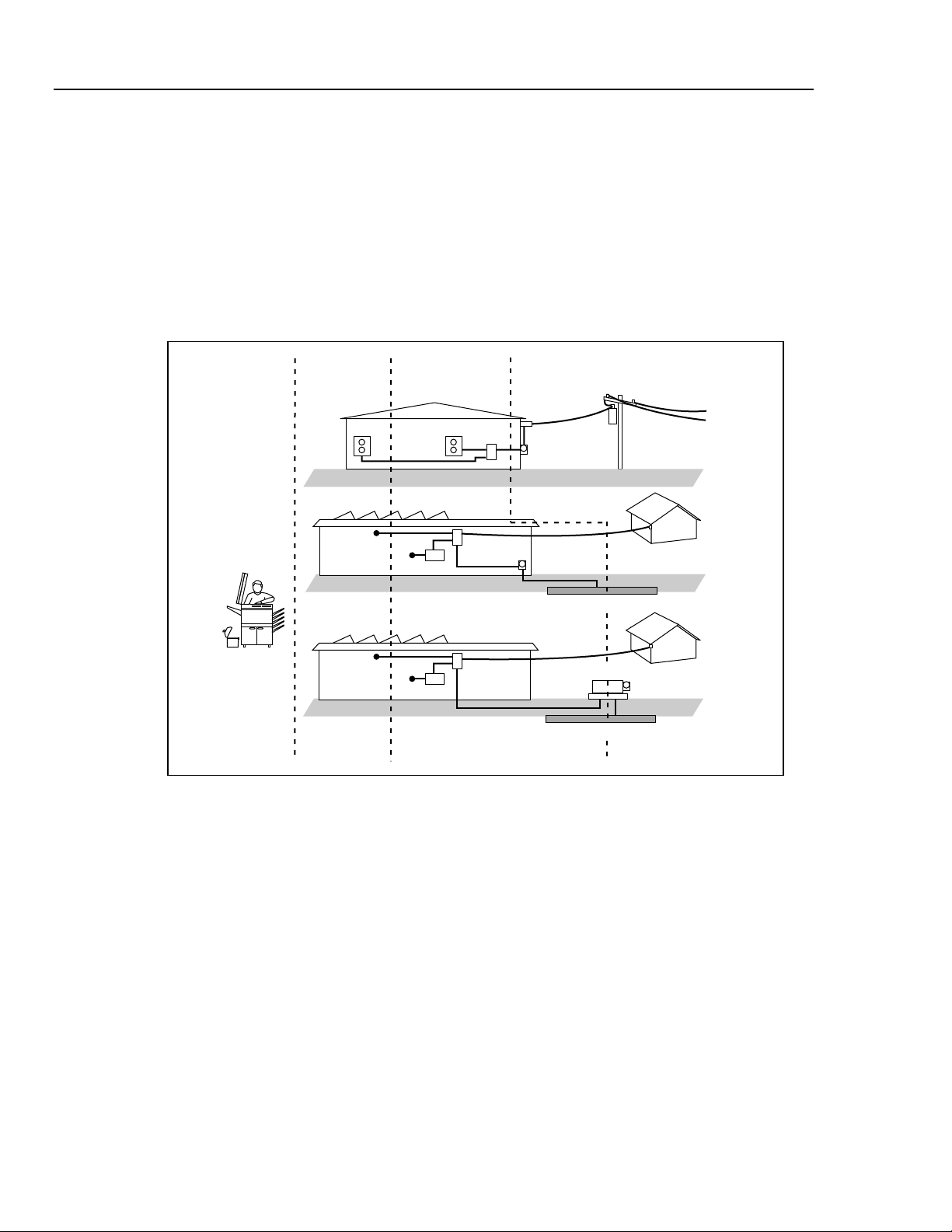
The IEC 61010 safety standard defines four Overvoltage (Installation) Categories (CAT I
to CAT IV) based on the magnitude of danger from transient impulses as shown in
Figure 1-1.
CAT I
Electronic
CAT II
Appliances,
PCs, TVs
Figure 1-1. IEC 61010 Measurement Category (CAT) Levels
CAT III
MC Panels, etc.
Service
Entrance
Service
Entrance
Service
Entrance
CAT IV
Meter
Meter
Underground Service
Transformer
Underground Service
Outbuilding
Outbuilding
Meter
cat_levels.eps
1-6
The IEC 61010 Measurement CAT level indicates the level of protection the instrument
provides against impulse withstand voltage.
CAT I equipment is designed to protect against transients from high-voltage, low-energy
sources, such as electronic circuits or a copy machine.
CAT II equipment is designed to protect against transients from energy-consuming
equipment supplied from the fixed installation, such as TVs, PCs, portable tools, and
other household appliances.
CAT III equipment is designed to protect against transients in equipment in fixed
equipment installations, such as distribution panels, feeders and short branch circuits, and
lighting systems in large buildings.
CAT IV equipment is designed to protect against transients from the primary supply
level, such as an electricity meter or an overhead or underground utility service.
Page 17

Introduction and Specifications
Organization of the Calibration Manual 1
Organization of the Calibration Manual
This calibration manual is divided into the following chapters:
Chapter 1 – Introduction and Specifications
This chapter introduces the Fluke 8845A and 8846A Digital Multimeters, describing their
features, and accessories. This chapter also discusses use of the Calibration Manual and
the various conventions used in describing the meter’s circuitry and presents a complete
set of specifications.
Chapter 2 – General Maintenance
Chapter 2 provides maintenance information covering handling, cleaning, and fuse
replacement. Access and reassembly procedures are also explained in this chapter.
Chapter 3 – Performance Test and Calibration
This chapter provides performance verification procedures related to the specifications
presented in Chapter 1. To maintain these specifications, a full adjustment/calibration
procedure is also presented.
Chapter 4 – List of Replaceable Parts
Chapter 4 includes parts lists for all standard assemblies and information on how and
where to order parts.
Operating Instructions
Full operating instructions are provided in the Fluke 8845A/8846A Users Manual.
Reference to these instructions may be necessary during some of the maintenance and
repair procedures presented in this Calibration Manual.
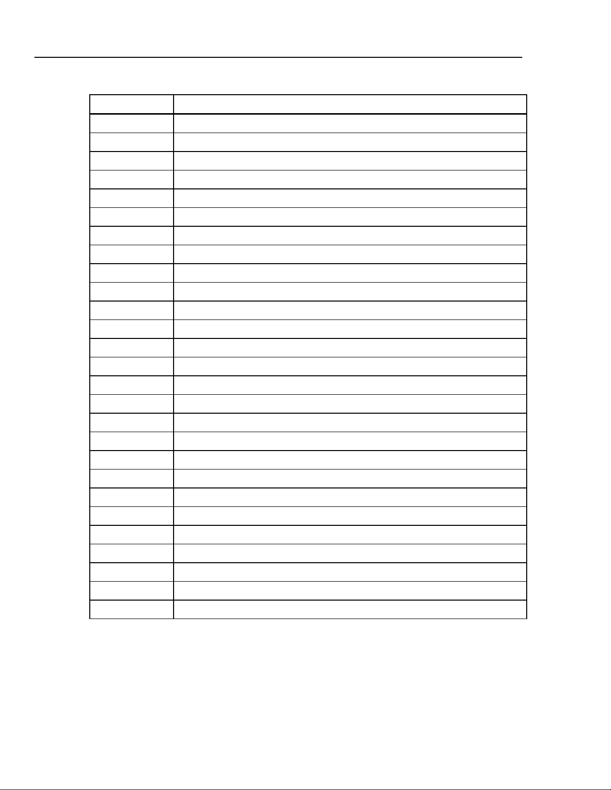
Accessories
Table 1-3 lists the available accessories for the 8845A and 8846A.
Table 1-3. Accessories
Model/Fluke PN Description
TL71 Test Lead Set, Premium DMM
TL910 Precision Electronic Probe Set
TL80A Basic Electronic DMM Test Set
8845A-TPIT Test Probe Ic Tip (Set Red & Black)
8845A-EFPT Extended Fine Pt Tip Adap Set (Set Red/Black)
884X-SHORT 4-Wire short
TL2X4W-PTII 2x4 Wire Ohms 1000V Test lead
884X-RTD 100 Ohm RTD Temperature Probe
884X-512M USB Memory 512M
1-7
Page 18
8845A/8846A
Calibration Manual
Model/Fluke PN Description
884X-1G USB Memory 1 GB
884X-USB USB to RS232 cable adapter
884X-ETH Ethernet Interface Cable
RS43 RS232 Cable (RS43, 2m)
Y8021 IEEE488 cable (1m)
Y8022 IEEE488 cable (2m)
884X-CASE Black Case
FVF-UG FlukeView Forms Software Upgrade - NO cable
FVF-SC4 Flukeview Forms W/Cable For 8845/8846
FVF-SC5 Flukeview Forms -Basic For 8845/8846
Y8846S Rack Mount Kit 8845A & 8846A Single
Table 1-3. Accessories (cont)
Y8846D Rack Mount Kit 8845A & 8846A Dual
FUSE Fuse,11A,1000V,Fast.406inx1.5in,Bulk
FUSE Fuse,.440 mA,1000V,Fast,.406X1.375,Bulk
2132558 Calibration, Traceable, w/ Data
1259800 Calibration, Traceable, w/o Data
1256480 Calibration, Z540 Traceable, w/ Data
1258910 Calibration, Z540 Traceable, w/o Data
1256990 Calibration, Accredited
1024830 Agreement, Extended Warranty
2426684 Agreement, Calibration, Traceable, w/ Data
1028820 Agreement, Calibration, Traceable, w/o Data
1259170 Agreement, Calibration, Z540 Traceable, w/ Data
1258730 Agreement, Calibration, Z540 Traceable, w/o Data
1259340 Agreement, Calibration, Accredited
2441827 Agreement, Calibration, Primary Standards Lab
1540600 Agreement, Calibration, Artifact
1-8
Page 19

Introduction and Specifications
General Specifications 1
General Specifications
Power
Voltage
100 V Setting ...................................................... 90 V to 110 V
120 V Setting ...................................................... 108 V to 132 V
220 V Setting ...................................................... 198 V to 242 V
240 V Setting ...................................................... 216 V to 264 V
Frequency ............................................................... 47 Hz to 440 Hz. Automatically sensed at power-on.
Power Consumption................................................ 28 VA peak (12 Watt average)
Dimensions
Height...................................................................... 88 mm (3.46 in.)
Width....................................................................... 217 mm (8.56 in.)
Depth ...................................................................... 297 mm (11.7 in.)
Weight..................................................................... 3.6 kg (8.0 lbs)
Shipping Weight...................................................... 5.0 kg (11.0 lbs)
Display
Vacuum Fluorescent Display, dot matrix
Environment
Temperature
Operating ............................................................ 0 °C to 55 °C
Storage ............................................................... -40 °C to 70 °C
Warm Up............................................................. 1 hour to full uncertainty specifications
Relative Humidity (non-condensing)
Operating ............................................................ 0 °C to 28 °C <90 %
Storage ............................................................... -40 °C to 70 °C <95 %
Altitude
Operating ............................................................ 2,000 Meters
Storage ............................................................... 12,000 Meters
Vibration and Shock................................................ Complies with Mil-T-28800F Type III, Class 5 (Sine only)
28 °C to 40 °C <80 %
40 °C to 55 °C <50 %
Safety
Designed to comply with IEC 61010-1:2000-1, UL 61010-1A1, CAN/CSA-C22.2 No. 61010.1, CAT I 1000V/CAT II 600V
EMC
Designed to comply with IEC 61326-1:2000-11 (EMC) when used with shielded communications cables. This Meter has
shown susceptibility to radiated frequencies greater than 1 V/m from 250 to 450 MHz.
Triggering
Samples per Trigger ...........................................1 to 50,000
Trigger Delay ...................................................... 0 s to 3600 s; in 10 µS increments
External Trigger Delay ........................................ <1 mS
External Trigger Jitter ......................................... <500 µS
Trigger Input ....................................................... TTL Levels
Trigger Output..................................................... 5 V maximum (open collector)
1-9
Page 20

8845A/8846A
Calibration Manual
Memory
8845A ................................................................. 5,000 measurements, internal only
8846A ................................................................. 5,000 measurements, internal, and up to 2 Gigabyte capacity with USB
Math Functions
Zero, dBm, dB, MX+B, Trend-plot, Histogram, Statistics (min/max/average/standard deviation), and Limit Test
Electrical
Input Protection .................................................... 1000 V all ranges
Overrange .............................................................. 20 % on all ranges except 1000 V dc, 1000 V ac (8846A),
Remote Interfaces
RS-232 (RS-232 to USB cable available to connect the Meter to a PC USB port. See Accessories)
IEEE 488.2
LAN
Warranty
One year
memory module (available separately, see “Accessories”) through
front-panel USB port
750 V ac (8845A), Diode, and 10 A ranges
Electrical Specifications
Accuracy specifications are valid for 6½ digit resolution mode after at least a 1-hour warm-up with Auto Zero enabled.
24-hour specifications are relative to calibration standards and assume a controlled electromagnetic environment per
EN 61326-1:2000-11
Note
NPLC stands for Number of Power Line Cycles and refers to the number of cycles of the line
voltage.
DC Voltage Specifications
Maximum Input...................................................... 1000 V on any range
Common Mode Rejection..................................... 140 dB at 50 or 60 Hz ±0.1 % (1 kΩ unbalance)
Normal Mode Rejection ........................................ 60 dB for NPLC of 1 or greater with dc filter off and power line
Measurement Method ........................................... Multi-ramp A/D
A/D Linearity.......................................................... 0.0002 % of measurement +0.0001 % of range
Input Bias Current................................................. <30 pA at 25 °C
Autozero Off Operation ........................................ Following instrument warm-up at calibration temperature ±1 °C and
Settling Considerations........................................ Measurement settling times are affected by source impedance, cable
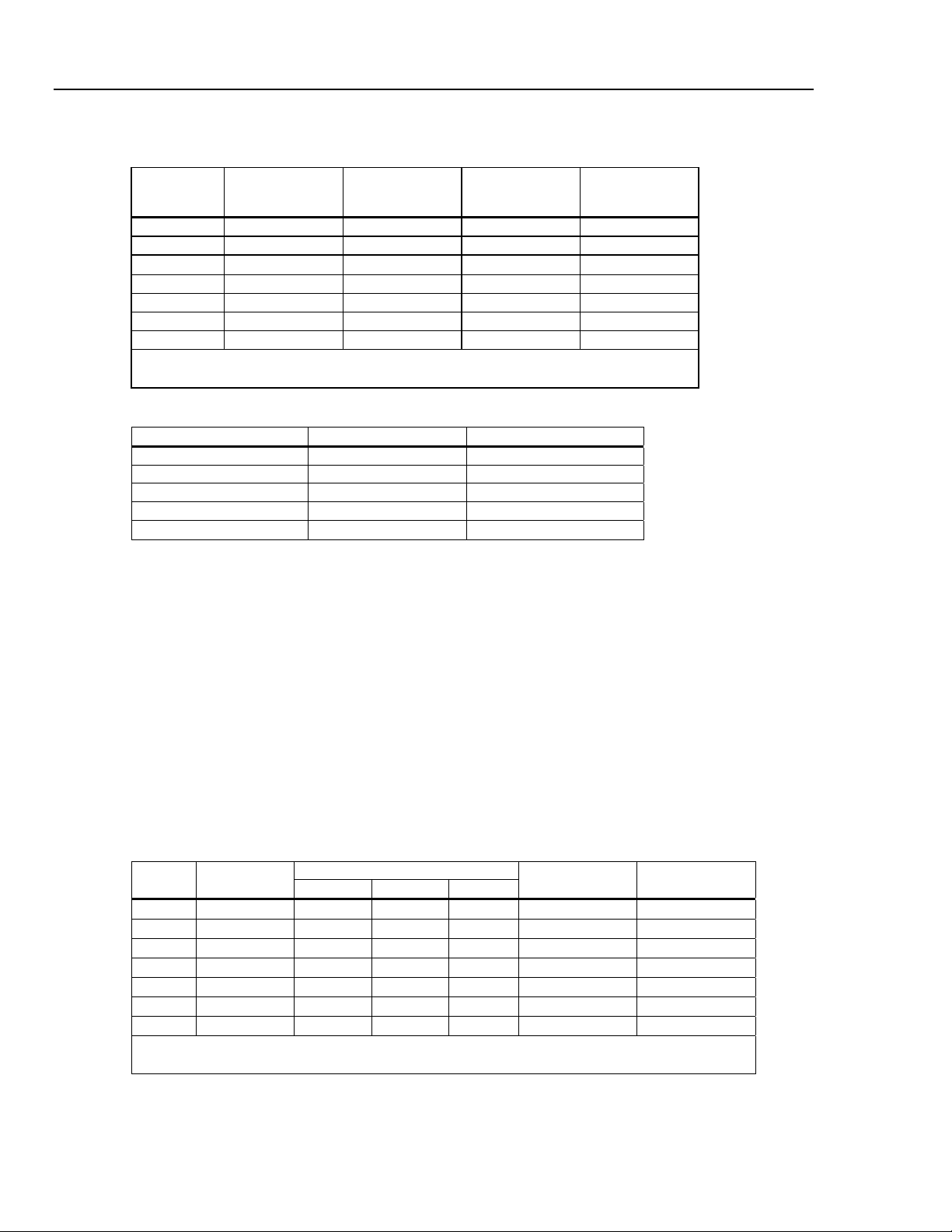
Input Characteristics
Range Resolution
100 mV 100.0000 mV 10 µV 1 µV 100 nV
1 V 1.000000 V 100 µV 10 µV 1 µV
10 V 10.00000 V 1 mV 100 µV 10 µV
100 V 100.0000 V 10 mV 1 mV 100 µV
1000 V 1,000.000 V 100 mV 10 mV 1 mV
[1] Inputs beyond ±14 V are clamped through 200 kΩ typical. 10 MΩ is default input impedance.
4½ Digits 5½ Digits 6½ Digits
frequency ±0.1 %
100 dB for NPLC of 1 or greater with dc filter on and power line
frequency ±0.1 %
less than 10 minutes, add error: 0.0002 % range additional error + 5
μV.
dielectric characteristics, and input signal changes.
Resolution
Input Impedance
10 MΩ or >10 GΩ
10 MΩ or >10 GΩ
10 MΩ or >10 GΩ
10 MΩ ±1%
10 MΩ ±1%
[1]
[1]
[1]
1-10
Page 21
Introduction and Specifications
Electrical Specifications 1
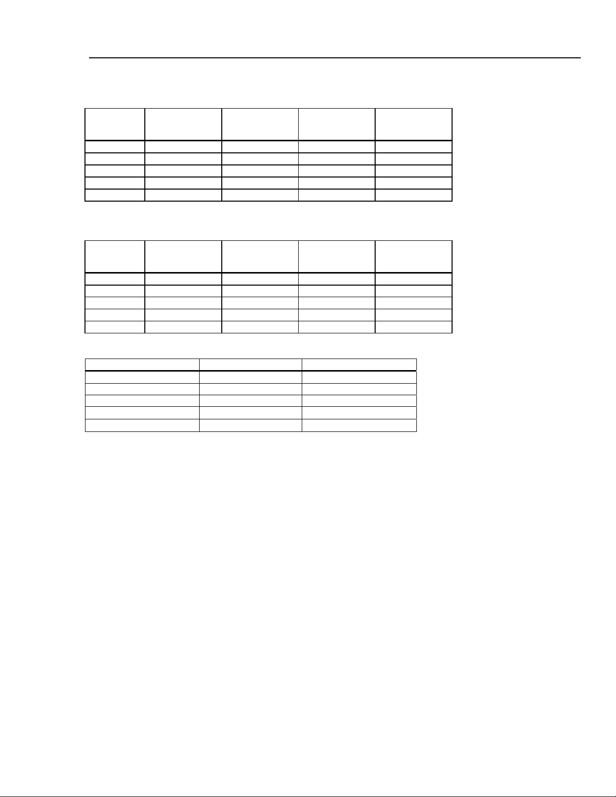
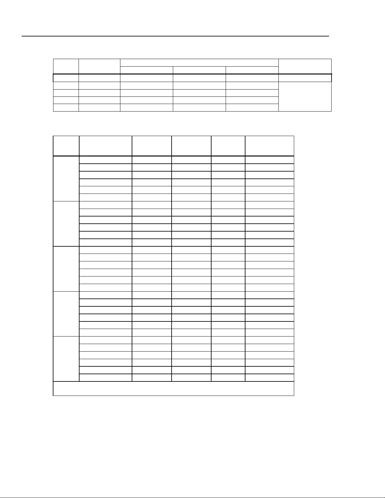
8846A Accuracy
Accuracy is given as ± (% measurement + % of range)
Range
100 mV 0.0025 + 0.003 0.0025 + 0.0035 0.0037 + 0.0035 0.0005 + 0.0005
1 V 0.0018 + 0.0006 0.0018 + 0.0007 0.0025 + 0.0007 0.0005 + 0.0001
10 V 0.0013 + 0.0004 0.0018 + 0.0005 0.0024 + 0.0005 0.0005 + 0.0001
100 V 0.0018 + 0.0006 0.0027 + 0.0006 0.0038 + 0.0006 0.0005 + 0.0001
1000 V 0.0018 + 0.0006 0.0031 + 0.001 0.0041 + 0.001 0.0005 + 0.0001
24 Hour
(23 ±1 °C)
90 Days
(23 ±5 °C)
1 Year
(23 ±5 °C)
Temperature
Coefficient/ °C
Outside 18 to 28 °C
8845A Accuracy
Accuracy is given as ± (% measurement + % of range)
Range
100 mV 0.003 + 0.003 0.004 + 0.0035 0.005 + 0.0035 0.0005 + 0.0005
1 V 0.002 + 0.0006 0.003 + 0.0007 0.004 + 0.0007 0.0005 + 0.0001
10 V 0.0015 + 0.0004 0.002 + 0.0005 0.0035 + 0.0005 0.0005 + 0.0001
100 V 0.002 + 0.0006 0.0035 + 0.0006 0.0045 + 0.0006 0.0005 + 0.0001
1000 V 0.002 + 0.0006 0.0035 + 0.0010 0.0045 + 0.0010 0.0005 + 0.0001
24 Hour
(23 ±1 °C)
90 Days
(23 ±5 °C)
1 Year
(23 ±5 °C)
Temperature
Coefficient/ °C
Outside 18 to 28 °C
Additional Errors
Digits NPLC Additional Noise Error
6½ 100 0 % of range
6½ 10 0 % of range
5½ 1 0.001 % of range
5½ .2
4½ 0.02
0.001 % of range +20 μV
0.01 % of range +20 μV
AC Voltage Specifications
AC Voltage specifications are for ac sinewave signals >5 % of range. For inputs from 1 % to 5 % of range and <50 kHz,
add an additional error of 0.1 % of range, and for 50 to 100 kHz, add 0.13 % of range.
Maximum Input...................................................... 750 V rms or 1000 V peak (8845A), 1000 V rms or 1414 V peak
(8846A) or 8 x 10
range.
Measurement Method ........................................... AC-coupled true-rms. Measures the ac component of input with up to
1000 V dc bias on any range.
AC Filter Bandwidth:
Slow .................................................................... 3 Hz – 300 kHz
Medium ............................................................... 20 Hz – 300 kHz
Fast..................................................................... 200 Hz – 300 kHz
Common Mode Rejection..................................... 70 dB at 50 Hz or 60 Hz ±0.1 % (1 kΩ unbalance)
Maximum Crest Factor .........................................5:1 at Full Scale
Additional Crest Factor Errors (<100 Hz) ........... Crest factor 1-2, 0.05 % of full scale
Crest factor 2-3, 0.2 % of full scale
Crest factor 3-4, 0.4 % of full scale
Crest factor 4-5, 0.5 % of full scale
7
volts-Hertz product (whichever is less) for any
1-11
Page 22
8845A/8846A
Calibration Manual
Input Characteristics
Range Resolution
100 mV 100.0000 mV 10 µV 1 µV 100 nV
1 V 1.000000 V 100 µV 10 µV 1 µV
10 V 10.00000 V 1 mV 100 µV 10 µV
100 V 100.0000 V 10 mV 1 mV 100 µV
1000 V 1,000.000 V 100 mV 10 mV 1 mV
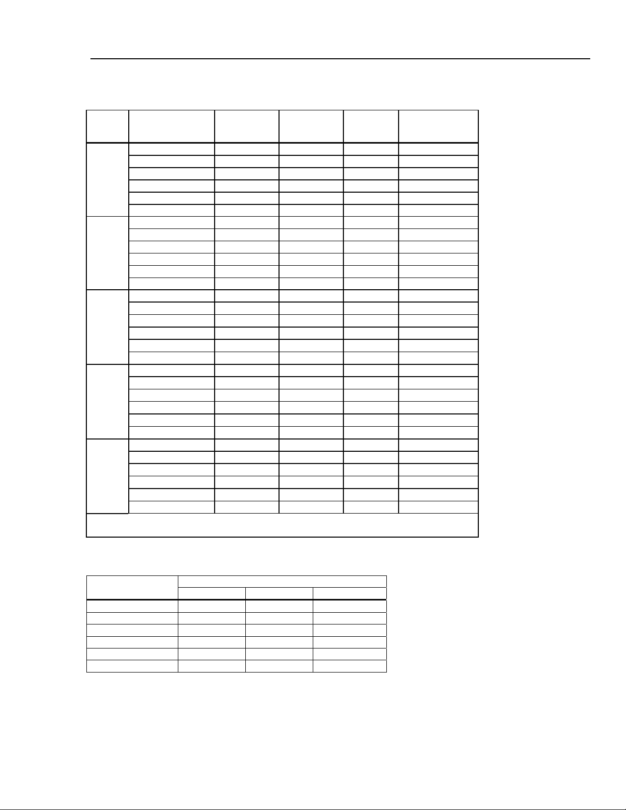
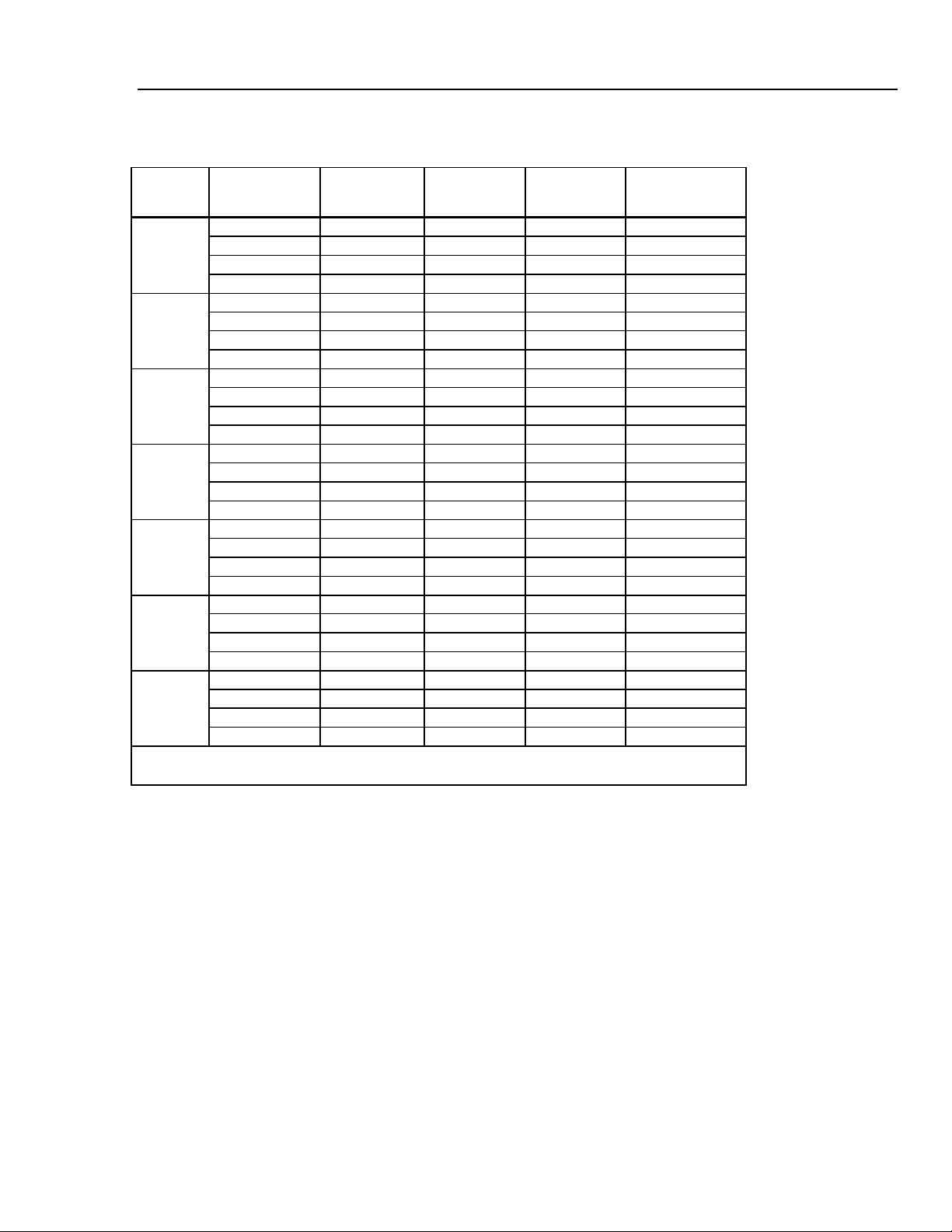
8846A Accuracy
Accuracy is given as ± (% measurement + % of range)
Range Frequency
100 mV
1 V
10 V
100 V
1000 V
[1] Typically 30 % reading error at 1 MHz
[2] 1000 Volt range is limited to 8 X 10
Resolution
4½ Digits 5½ Digits 6½ Digits
24 Hour
(23 ±1 °C)
90 Days
(23 ±5 °C)
1 Year
(23 ±5 °C)
Temperature
Coefficient/ °C
Outside 18 to 28 °C
3 – 5 Hz 1.0 + 0.03 1.0 + 0.04 1.0 + 0.04 0.1 + 0.004
5 – 10 Hz 0.35 + 0.03 0.35 + 0.04 0.35 + 0.04 0.035 + 0.004
10 Hz – 20 kHz 0.04 + 0.03 0.05 + 0.04 0.06 + 0.04 0.005 + 0.004
20 – 50 kHz 0.1 + 0.05 0.11 + 0.05 0.12 + 0.05 0.011 + 0.005
50 – 100 kHz 0.55 + 0.08 0.6 + 0.08 0.6 + 0.08 0.06 + 0.008
100 – 300 kHz
[1]
4.0 + 0.50 4.0 + 0.50 4.0 + 0.50 0.20 + 0.02
3 – 5 Hz 1.0 + 0.02 1.0 + 0.03 1.0 + 0.03 0.1 + 0.003
5 – 10 Hz 0.35 + 0.02 0.35 + 0.03 0.35 + 0.03 0.035 + 0.003
10 Hz – 20 kHz 0.04 + 0.02 0.05 + 0.03 0.06 + 0.03 0.005 + 0.003
20 – 50 kHz 0.1 + 0.04 0.11 + 0.05 0.12 + 0.05 0.011 + 0.005
50 – 100 kHz 0.55 + 0.08 0.6 + 0.08 0.6 + 0.08 0.06 + 0.008
100 – 300 kHz
[1]
4.0 + 0.50 4.0 + 0.50 4.0 + 0.50 0.2 + 0.02
3 – 5 Hz 1.0 + 0.02 1.0 + 0.03 1.0 + 0.03 0.1 + 0.003
5 – 10 Hz 0.35 + 0.02 0.35 + 0.03 0.35 + 0.03 0.035 + 0.003
10 Hz – 20 kHz 0.04 + 0.02 0.05 + 0.03 0.06 + 0.03 0.005 + 0.003
20 – 50 kHz 0.1 + 0.04 0.11 + 0.05 0.12 + 0.05 0.011 + 0.005
50 – 100 kHz 0.55 + 0.08 0.6 + 0.08 0.6 + 0.08 0.06 + 0.008
100 –- 300 kHz
[1]
4.0 + 0.50 4.0 + 0.50 4.0 + 0.50 0.2 + 0.02
3 – 5 Hz 1.0 + 0.02 1.0 + 0.03 1.0 + 0.03 0.1 + 0.003
5 – 10 Hz 0.35 + 0.02 0.35 + 0.03 0.35 + 0.03 0.035 + 0.003
10 Hz – 20 kHz 0.04 + 0.02 0.05 + 0.03 0.06 + 0.03 0.005 + 0.003
20 – 50 kHz 0.1 + 0.04 0.11 + 0.05 0.12 + 0.05 0.011 + 0.005
50 – 100 kHz
100 – 300 kHz
[2]
0.55 + 0.08 0.6 + 0.08 0.6 + 0.08 0.06 + 0.008
[1][2]
4.0 + 0.5 4.0 + 0.50 4.0 + 0.50 0.2 + 0.02
7
volt-Hertz
Input Impedance
1 MΩ ±2 % shunted
by <100 pf
1-12
Page 23
Introduction and Specifications
Electrical Specifications 1
8845A Accuracy
Accuracy is given as ± (% measurement + % of range)
Range
100 mV
Frequency
(Hz)
3 – 5 Hz 1.0 + 0.03 1.0 + 0.04 1.0 + 0.04 0.10 + 0.004
5 – 10 Hz 0.35 + 0.03 0.35 + 0.04 0.35 + 0.04 0.035 + 0.004
10 Hz – 20 kHz 0.04 + 0.03 0.05 + 0.04 0.06 + 0.04 0.005 + 0.004
20 – 50 kHz 0.1 + 0.05 0.11 + 0.05 0.12 + 0.05 0.011 + 0.005
1 V
50 – 100 kHz 0.55 + 0.08 0.6 + 0.08 0.6 + 0.08 0.06 + 0.008
100 – 300 kHz
3 – 5 Hz 1.0 + 0.02 1.0 + 0.03 1.0 + 0.03 0.1 + 0.003
[1]
4.0 + 0.50 4.0 + 0.50 4.0 + 0.50 0.2 + 0.02
5 – 10 Hz 0.35 + 0.02 0.35 + 0.03 0.35 + 0.03 0.035 + 0.003
10 Hz – 20 kHz 0.04 + 0.02 0.05 + 0.03 0.06 + 0.03 0.005 + 0.003
20 – 50 kHz 0.1 + 0.04 0.11 + 0.05 0.12 + 0.05 0.011 + 0.005
10 V
50 – 100 kHz 0.55 + 0.08 0.6 + 0.08 0.6 + 0.08 0.06 + 0.008
100 – 300 kHz
3 – 5 Hz 1.0 + 0.02 1.0 + 0.03 1.0 + 0.03 0.1 + 0.003
[1]
4.0 + 0.50 4.0 + 0.50 4.0 + 0.50 0.2 + 0.02
5 – 10 Hz 0.35 + 0.02 0.35 + 0.03 0.35 + 0.03 0.035 + 0.003
10 Hz – 20 kHz 0.04 + 0.02 0.05 + 0.03 0.06 + 0.03 0.005 + 0.003
20 – 50 kHz 0.1 + 0.04 0.11 + 0.05 0.12 + 0.05 0.011 + 0.005
50 – 100 kHz 0.55 + 0.08 0.6 + 0.08 0.6 + 0.08 0.06 + 0.008
[1]
4.0 + 0.50 4.0 + 0.50 4.0 + 0.50 0.2 + 0.02
100 V
100 – 300 kHz
3 – 5 Hz 1.0 + 0.02 1.0 + 0.03 1.0 + 0.03 0.1 + 0.003
5 – 10 Hz 0.35 + 0.02 0.35 + 0.03 0.35 + 0.03 0.035 + 0.003
10 Hz – 20 kHz 0.04 + 0.02 0.05 + 0.03 0.06 + 0.03 0.005 + 0.003
20 – 50 kHz 0.1 + 0.04 0.11 + 0.05 0.12 + 0.05 0.011 + 0.005
50 – 100 kHz 0.55 + 0.08 0.6 + 0.08 0.6 + 0.08 0.06 + 0.008
[1]
4.0 + 0.50 4.0 + 0.50 4.0 + 0.50 0.2 + 0.02
750 V
100 – 300 kHz
3 –- 5 Hz 1.0 + 0.02 1.0 + 0.03 1.0 + 0.03 0.1 + 0.003
5 – 10 Hz 0.35 + 0.02 0.35 + 0.03 0.35 + 0.03 0.035 + 0.003
10 Hz – 20 kHz 0.04 + 0.02 0.05 + 0.03 0.06 + 0.03 0.005 + 0.003
20 – 50 kHz 0.1 + 0.04 0.11 + 0.05 0.12 + 0.05 0.011 + 0.005
50 – 100 kHz
100 – 300 kHz
[1] Typically 30 % reading error at 1 MHz
[2] 750 Volt range is limited to 8 X 10
[2]
0.55 + 0.08 0.6 + 0.08 0.6 + 0.08 0.06 + 0.008
[1] [2]
4.0 + 0.5 4.0 + 0.5 4.0 + 0.5 0.2 + 0.02
24 Hour
(23 ±1 °C)
7
volt-Hertz
90 Days
(23 ±5 °C)
1 Year
(23 ±5 °C)
Temperature
Coefficient/ °C
Outside 18 to 28 °C
Additional Low Frequency Errors
Error is stated as % of reading.
Frequency
3HZ (slow) 20HZ (medium) 200HZ (fast)
AC Filter
10 – 20 Hz 0 0.25 –
20 – 40 Hz 0 0.02 –
40 – 100 Hz 0 0.01 0.55
100 – 200 Hz 0 0 0.2
200 Hz – 1 kHz 0 0 0.02
>1 kHz 0 0 0
1-13
Page 24
8845A/8846A
Calibration Manual
Resistance
Specifications are for 4-wire resistance function, 2 x 4-wire resistance, or 2-wire resistance with zero. If zero is not used,
add 0.2 Ω for 2-wire resistance plus lead resistance, and add 20 mΩ for 2 x 4-wire resistance function.
Measurement Method ........................................... Current source referenced to LO input
Max. Lead Resistance (4-wire ohms) ..................10 % of range per lead for 100 Ω, 1 kΩ ranges. 1 kΩ per lead on all
Input Protection .................................................... 1000 V on all ranges
Common Mode Rejection..................................... 140 dB at 50 or 60 Hz ± 0.1 % (1 kΩ unbalance)
Normal Mode Rejection ........................................ 60 dB for NPLC of 1 or greater with dc filter off and power line
Input Characteristics
Range Resolution
10 Ω
100 Ω 100.0000 Ω 10 mΩ 1 mΩ 100 μΩ
1 kΩ 1.000000 kΩ 100 mΩ 10 mΩ 1 mΩ
10 kΩ 10.00000 kΩ 1 Ω 100 mΩ 10 mΩ 100 μA/6 V
100 kΩ 100.0000 kΩ 10 Ω 1 Ω 100 mΩ 100 μA/13 V
1 MΩ 1.000000 MΩ 100 Ω 10 Ω 1 Ω 10 μA/13 V
10 MΩ 10.00000 MΩ 1 kΩ 100 Ω 10 Ω 1 μA/13 V
100 MΩ 100.0000 MΩ 10 kΩ 1 kΩ 100 Ω 1 μA || 10 MΩ/10 V
1.0 GΩ
[1] 8846A Only
other ranges
frequency ±0.1 %
100 dB for NPLC of 1 or greater with dc filter on and power line
frequency ±0.1 %
Resolution
[1]
10.00000 Ω 1 mΩ 100 μΩ 10 μΩ
[1]
1.000000 GΩ 100 kΩ 10 kΩ 1 kΩ 1 μA || 10 MΩ/10 V
4½ Digits 5½ Digits 6½ Digits
Source Current
5 mA/13 V
1 mA/6 V
1 mA/6 V
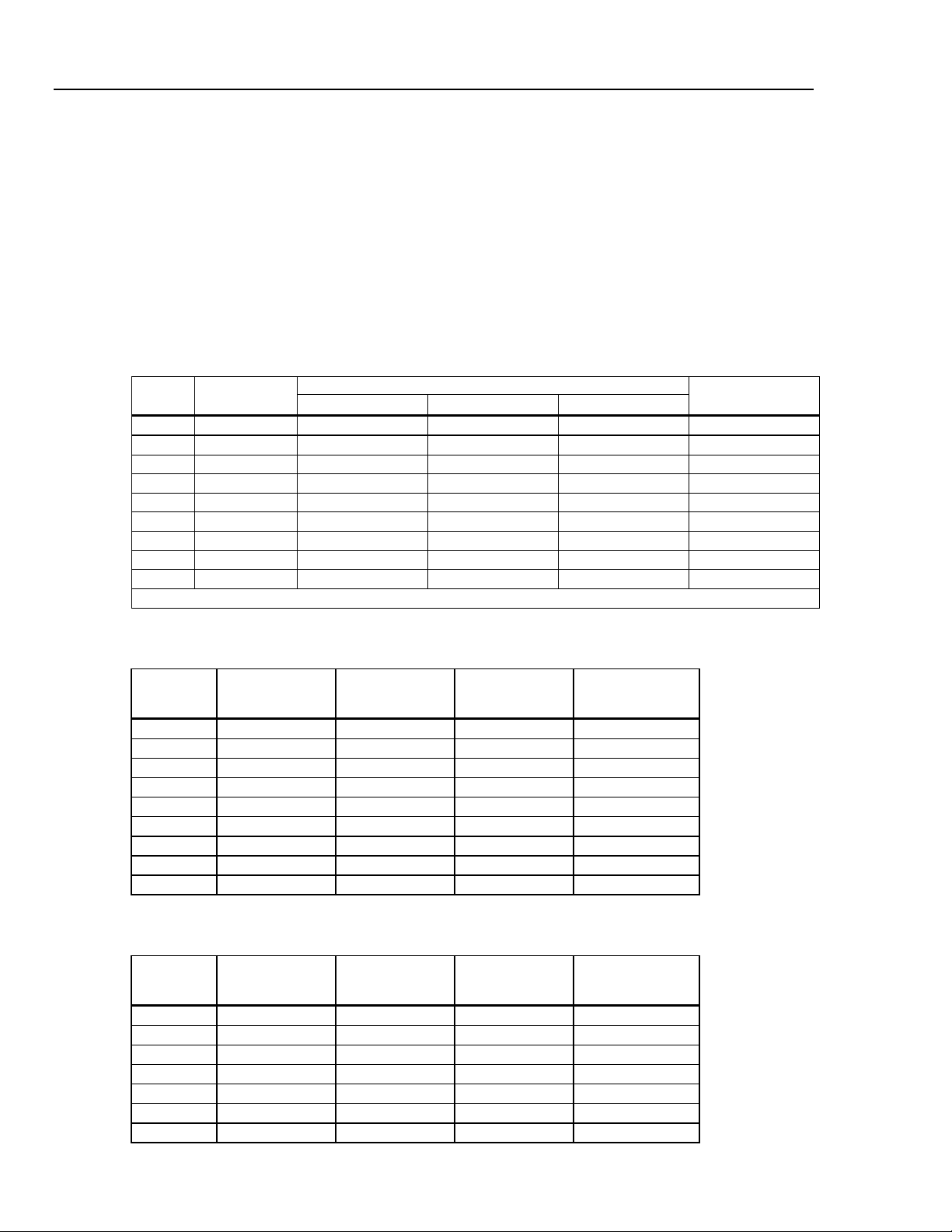
8846A Accuracy
Accuracy is given as ± (% measurement + % of range)
Range
10 Ω 0.003 + 0.01 0.008 + 0.03 0.01+ 0.03 0.0006 + 0.0005
100 Ω 0.003 + 0.003 0.008 + 0.004 0.01 + 0.004 0.0006 + 0.0005
1 kΩ 0.002 + 0.0005 0.008 + 0.001 0.01 + 0.001 0.0006 + 0.0001
10 kΩ 0.002 + 0.0005 0.008 + 0.001 0.01 + 0.001 0.0006 + 0.0001
100 kΩ 0.002 + 0.0005 0.008 + 0.001 0.01 + 0.001 0.0006 + 0.0001
1 MΩ 0.002 + 0.001 0.008 + 0.001 0.01 + 0.001 0.001 + 0.0002
10 MΩ 0.015 + 0.001 0.02 + 0.001 0.04 + 0.001 0.003 + 0.0004
100 MΩ 0.3 + 0.01 0.8 + 0.01 0.8 + 0.01 0.15 + 0.0002
1 GΩ 1.0 + 0.01 1.5 + 0.01 2.0 + 0.01 0.6 + 0.0002
24 Hour
(23 ±1 °C)
90 Days
(23 ±5 °C)
1 Year
(23 ±5 °C)
Temperature
Coefficient/ °C
Outside 18 to 28 °C
8845A Accuracy
Accuracy is given as ± (% measurement + % of range)
Range
100 Ω 0.003 + 0.003 0.008 + 0.004 0.01 + 0.004 0.0006 + 0.0005
1 kΩ 0.002 + 0.0005 0.008 + 0.001 0.01 + 0.001 0.0006 + 0.0001
10 kΩ 0.002 + 0.0005 0.008 + 0.001 0.01 + 0.001 0.0006 + 0.0001
100 kΩ 0.002 + 0.0005 0.008 + 0.001 0.01 + 0.001 0.0006 + 0.0001
1 MΩ 0.002 + 0.001 0.008 + 0.001 0.01 + 0.001 0.0010 + 0.0002
10 MΩ 0.015 + 0.001 0.02 + 0.001 0.04 + 0.001 0.0030 + 0.0004
100 MΩ 0.3 + 0.01 0.8 + 0.01 0.8 + 0.01 0.1500 + 0.0002
24 Hour
(23 ±1 °C)
90 Days
(23 ±5 °C)
1 Year
(23 ±5 °C)
Temperature
Coefficient/ °C
Outside 18 to 28 °C
1-14
Page 25
Introduction and Specifications
Electrical Specifications 1
Additional Ohms Errors
Digits NPLC Additional Noise Error
6½ 100 0 % of range
6½ 10 0 % of range
5½ 1 0.001 % of range
5½ 0.2
4½ 0.02
0.001 % of range ±20 mΩ
0.01 % of range ±20 mΩ
DC Current
Input Protection .................................................... Tool-accessible 11 A/1000 V and 440 mA/1000 V fuses
Common Mode Rejection.....................................140 dB at 50 or 60 Hz ±0.1 % (1 kΩ unbalance)
Normal Mode Rejection........................................ 60 dB for NPLC of 1 or greater with dc filter off and power line
frequency ±0.1 %
100 dB for NPLC of 1 or greater with dc filter on and power line
frequency ±0.1 %
Input Characteristics
Range Resolution
100 µA 100.0000 µA 10 nA 1 nA 100 pA
1 mA 1.000000 mA 100 nA 10 nA 1 nA
10 mA 10.00000 mA
100 mA 100.0000 mA 10 µA
1 A 1.000000 A 100 µA 10 µA
[1]
3 A
10 A 10.00000 A 1 mA 100 µA 10 µA
[1] Part of 10 A range.
3.00000A 1 mA 100 µA 10 µA
4½ Digits 5½ Digits 6½ Digits
1 μA
Resolution
100 nA 10 nA
1 μA
100 nA
1 μA
Shunt Resistance
(Ohms)
100 Ω
100 Ω
1 Ω
1 Ω
0.01 Ω
0.01 Ω
0.01 Ω
Burden Voltage
<0.015 V
<0.15 V
<0.025 V
<0.25 V
<0.05 V
<0.15 V
<0.5 V
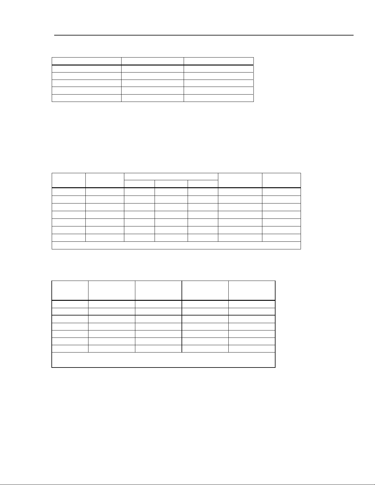
Accuracy (8846A)
Accuracy is given as ± (% measurement + % of range)
Range
100 µA 0.01 + 0.02 0.04 + 0.025 0.05 + 0.025 0.002 + 0.003
1 mA 0.007 + 0.005 0.030 + 0.005 0.05 + 0.005 0.002 + 0.0005
10 mA
100 mA 0.01 + 0.004 0.03 + 0.005 0.05 + 0.005 0.002 + 0.0005
[2]
1 A
[1][2]
3 A
[2]
10 A
[1] Part of 10 A range
[2] Available at front panel connectors only
24 Hour
(23 ±1 °C)
0.007 + 0.02 0.03 + 0.02 0.05 + 0.02 0.002 + 0.002
0.03 + 0.02 0.04 + 0.02 0.05 + 0.02 0.005 + 0.001
0.05 + 0.02 0.08 + 0.02 0.1 + 0.02 0.005 + 0.002
0.1 + 0.008 0.12 + 0.008 0.15 + 0.008 0.005 + 0.0008
90 Days
(23 ±5 °C)
1 Year
(23 ±5 °C)
Temperature
Coefficient/ °C
Outside 18 to 28 °C
1-15
Page 26
8845A/8846A
Calibration Manual
Accuracy (8845A)
Accuracy is given as ± (% measurement + % of range)
Range
100 µA 0.01 + 0.02 0.04 + 0.025 0.05 + 0.025 0.002 + 0.003
1 mA 0.007 + 0.005 0.030 + 0.005 0.05 + 0.005 0.002 + 0.0005
10 mA
100 mA 0.01 + 0.004 0.03 + 0.005 0.05 + 0.005 0.002 + 0.0005
[2]
1 A
[1][2]
3 A
10 A
[1] Part of 10 A range
[2] Available at front panel connectors only
Additional Current Errors
6½ 100 0 % of range
6½ 10 0 % of range
5½ 1 0.001 % of range
5½ 0.2
4½ 0.02
24 Hour
(23 ±1 °C)
90 Days
(23 ±5 °C)
1 Year
(23 ±5 °C)
0.007 + 0.02 0.03 + 0.02 0.05 + 0.02 0.002 + 0.002
0.03 + 0.04 0.08 + 0.02 0.05 + 0.02 0.005 + 0.001
[2]
0.05 + 0.08 0.12 + 0.02 0.1 + 0.02 0.005 + 0.002
0.1 + 0.008 0.12 + 0.008 0.15 + 0.02 0.005 + 0.0008
Digits NPLC Additional Noise Error
0.001 % of range ±4 μA
0.01 % of range ±4 μA
Temperature
Coefficient/ °C
Outside 18 to 28 °C
AC Current
The following ac current specifications are for sinusoidal signals with amplitudes greater than 5 % of range. For inputs
from 1 % to 5 % of range, add an additional error of 0.1 % of range.
Input Protection .................................................... Tool accessible 11 A/1000 V and 440 mA/1000 V fuses.
Measurement Method........................................... ac-coupled true-rms, dc-coupled to the fuse and shunt (no blocking
capacitor)
AC Filter Bandwidth
Slow.................................................................... 3 Hz to 10 kHz
Medium............................................................... 20 Hz to 10 kHz
Fast.....................................................................200 Hz to 10 kHz
Maximum Crest Factor .........................................5:1 at full scale
Additional Crest Factor Errors (<100 Hz) ........... Crest factor 1-2, 0.05 % of full scale
Crest factor 2-3, 0.2 % of full scale
Crest factor 3-4, 0.4 % of full scale
Crest factor 4-5, 0.5 % of full scale
Input Characteristics
Range Resolution
[1]
100 μA
1 mA
100.0000 μA
[1]
1.000000 mA 100 nA 10 nA 1 nA
10 mA 10.00000 mA
4½ Digits 5½ Digits 6½ Digits
10 nA 1 nA 100 pA
1 μA
100 mA 100.0000 mA 10 µA
1 A 1.000000 A 100 µA 10 µA
3 A[2] 3.00000 A 1 mA 100 µA
Resolution
100 nA 10 nA
1 μA
100 nA
1 μA
10 μA
10 A 10.00000 A 1 mA 100 µA 10 µA
[1] 8846A Only
[2] Part of 10 A range
Shunt Resistance
(Ohms)
100 Ω
100 Ω
1 Ω
1 Ω
0.01 Ω
0.01 Ω
0.01 Ω
Burden Voltage
<0.015 V
<0.15 V
<0.025 V
<0.25 V
<0.05 V
<0.05 V
<0.5 V
1-16
Page 27
Introduction and Specifications
Electrical Specifications 1
8846A Accuracy
Accuracy is given as ± (% measurement + % of range)
Range
100 μA
1 mA
10 mA
100 mA
[2]
1 A
[1][2]
3 A
[2]
10 A
[1] Part of 10 A range
[2] Available only on front panel connectors
Frequency
(Hz)
3 – 5 Hz 1.0 + 0.04 1.0 + 0.04 1.0 + 0.04 0.1 + 0.006
5 – 10 Hz 0.3 + 0.04 0.3 + 0.04 0.3 + 0.04 0.035 + 0.006
10 Hz – 5 kHz 0.1 + 0.04 0.1 + 0.04 0.1 + 0.04 0.015 + 0.006
5 – 10 kHz 0.2 + 0.25 0.2 + 0.25 0.2 + 0.25 0.03 + 0.006
3 – 5 Hz 1.0 + 0.04 1.0 + 0.04 1.0 + 0.04 0.1 + 0.006
5 – 10 Hz 0.3 + 0.04 0.3 + 0.04 0.3 + 0.04 0.035 + 0.006
10 Hz – 5 kHz 0.1 + 0.04 0.1 + 0.04 0.1 + 0.04 0.015 + 0.006
5 – 10 kHz 0.2 + 0.25 0.2 + 0.25 0.2 + 0.25 0.03 + 0.006
3 – 5 Hz 1.0 + 0.04 1.0 + 0.04 1.0 + 0.04 0.1 + 0.006
5 – 10 Hz 0.3 + 0.04 0.3 + 0.04 0.3 + 0.04 0.035 + 0.006
10 Hz – 5 kHz 0.1 + 0.04 0.1 + 0.04 0.1+ 0.04 0.015 + 0.006
5 – 10 kHz 0.2 + 0.25 0.2 + 0.25 0.2 + 0.25 0.03 + 0.006
3 – 5 Hz 1.0 + 0.04 1.0 + 0.04 1.0 + 0.04 0.1 + 0.006
5 – 10 Hz 0.3 + 0.04 0.3 + 0.04 0.3 + 0.04 0.035 + 0.006
10 Hz – 5 kHz 0.1 + 0.04 0.1 + 0.04 0.1 + 0.04 0.015 + 0.006
5 – 10 kHz 0.2 + 0.25 0.2 + 0.25 0.2 + 0.25 0.03 + 0.006
3 – 5 Hz 1.0 + 0.04 1.0 + 0.04 1.0 + 0.04 0.1 + 0.006
5 – 10 Hz 0.3 + 0.04 0.3 + 0.04 0.3 + 0.04 0.035 + 0.006
10 Hz – 5 kHz 0.1 + 0.04 0.1 + 0.04 0.1 + 0.04 0.015 + 0.006
5 – 10 kHz 0.35 + 0.7 0.35 + 0.7 0.35 + 0.7 0.03 + 0.006
3 – 5 Hz 1.1 + 0.06 1.1 + 0.06 1.1 + 0.06 0.1 + 0.006
5 – 10 Hz 0.35 + 0.06 0.35 + 0.06 0.35 + 0.06 0.035 + 0.006
10 Hz – 5 kHz 0.15 + 0.06 0.15 + 0.06 0.15 + 0.06 0.015 + 0.006
5 – 10 kHz 0.35 + 0.7 0.35 + 0.7 0.35 + 0.7 0.03 + 0.006
3 – 5 Hz 2.0 + 0.06 2.0 + 0.06 2.0 + 0.06 0.2 + 0.006
5 – 10 Hz 1.1 + 0.06 1.1 + 0.06 1.1 + 0.06 0.1 + 0.006
10 Hz – 5 kHz 0.15 + 0.06 0.15 + 0.06 0.15 + 0.06 0.015 + 0.006
5 – 10 kHz 0.35 + 0.7 0.35 + 0.7 0.35 + 0.7 0.03 + 0.006
24 Hour
(23 ±1 °C)
90 Days
(23 ±5 °C)
1 Year
(23 ±5 °C)
Temperature
Coefficient/ °C
Outside 18 to 28 °C
1-17
Page 28
8845A/8846A
Calibration Manual
8845A Accuracy
Accuracy is given as ± (% measurement + % of range)
Range
10 mA
100 mA
[2]
1 A
[1][2]
3 A
10 A
[1] Part of the 10 A range
[2] Available only at front panel connectors
Frequency
(Hz)
3 – 5 Hz 1.0 + 0.04 1.0 + 0.04 1.0 + 0.04 0.1 + 0.006
5 – 10 Hz 0.3 + 0.04 0.3 + 0.04 0.3 + 0.04 0.035 + 0.006
10 Hz – 5 kHz 0.1 + 0.04 0.1 + 0.04 0.1+ 0.04 0.015 + 0.006
5 – 10 kHz 0.2 + 0.25 0.2 + 0.25 0.2 + 0.25 0.03 + 0.006
3 – 5 Hz 1.0 + 0.04 1.0 + 0.04 1.0 + 0.04 0.1 + 0.006
5 – 10 Hz 0.3 + 0.04 0.3 + 0.04 0.3 + 0.04 0.035 + 0.006
10 Hz – 5 kHz 0.1 + 0.04 0.1 + 0.04 0.1 + 0.04 0.015 + 0.006
5 – 10 kHz 0.2 + 0.25 0.2 + 0.25 0.2 + 0.25 0.03 + 0.006
[2]
3 – 5 Hz 1.0 + 0.04 1.0 + 0.04 1.0 + 0.04 0.1 + 0.006
5 – 10 Hz 0.3 + 0.04 0.3 + 0.04 0.3 + 0.04 0.035 + 0.006
10 Hz – 5 kHz 0.1 + 0.04 0.1 + 0.04 0.1 + 0.04 0.015 + 0.006
5 – 10 kHz 0.35 + 0.7 0.35 + 0.7 0.35 + 0.7 0.03 + 0.006
3 – 5 Hz 1.1 + 0.06 1.1 + 0.06 1.1 + 0.06 0.1 + 0.006
5 – 10 Hz 0.35 + 0.06 0.35 + 0.06 0.35 + 0.06 0.035 + 0.006
10 Hz – 5 kHz 0.15 + 0.06 0.15 + 0.06 0.15 + 0.06 0.015 + 0.006
5 – 10 kHz 0.35 + 0.7 0.35 + 0.7 0.35 + 0.7 0.03 + 0.006
3 – 5 Hz 1.1 + 0.04 1.1 + 0.04 1.1 + 0.04 0.2 + 0.006
5 – 10 Hz 0.35 + 0.04 0.35 + 0.04 0.35 + 0.04 0.1 + 0.006
10 Hz – 5 kHz 0.15 + 0.04 0.15 + 0.04 0.15 + 0.04 0.015 + 0.006
5 – 10 kHz 0.35 + 0.7 0.35 + 0.7 0.35 + 0.7 0.03 + 0.006
24 Hour
(23 ±1 °C)
90 Days
(23 ±5 °C)
1 Year
(23 ±5 °C)
Temperature
Coefficient/ °C
Outside 18 to 28 °C
Additional Low Frequency Errors
Error is stated as % of reading.
Frequency
10 – 20 Hz 0 0.25 –
20 – 40 Hz 0 0.02 –
40 – 100 Hz 0 0.01 0.55
100 – 200 Hz 0 0 0.2
200 Hz – 1 kHz 0 0 0.02
> 1 kHz 0 0 0
3HZ (slow) 20HZ (medium) 200HZ (fast)
AC Filter
Frequency
Gate Times............................................................. Programmable to 1 s, 100 ms, and 10 ms
Measurement Method ........................................... Flexible counting technique. AC-coupled input using the ac voltage
Settling Considerations........................................ When measuring frequency or period after a dc offset voltage change,
Measurement Considerations.............................. To minimize measurement errors, shield inputs from external noise
measurement function.
errors may occur. For the most accurate measurement, wait up to 1
second for the input blocking capacitor to settle.
when measuring low-voltage, low-frequency signals.
1-18
Page 29
Introduction and Specifications
Electrical Specifications 1
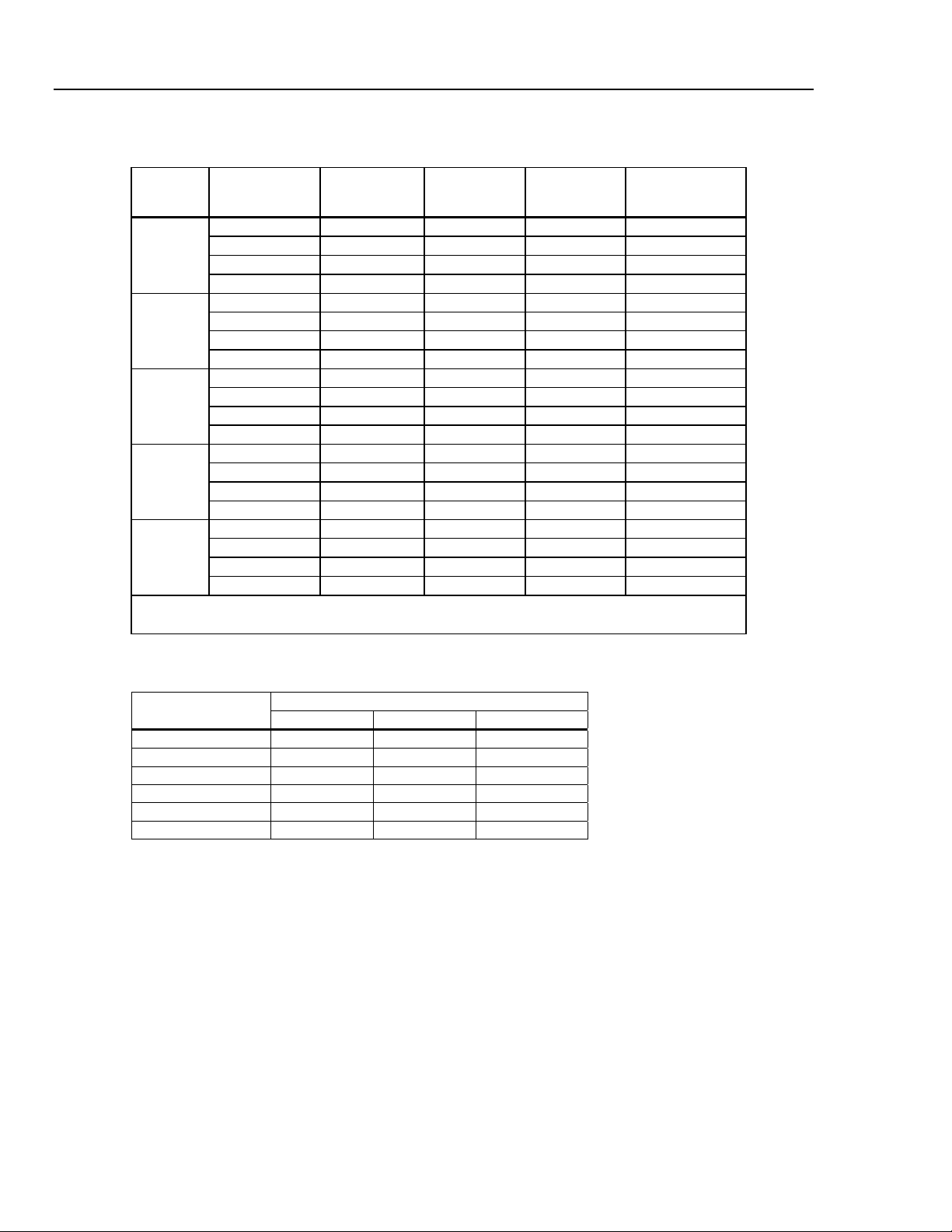
8846A Accuracy
Accuracy is given as ± % measurement
Range Frequency
100 mV to
1000 V
[1] Input >100 mV. For 10 – 100 mV, multiply percent measurement error by 10.
[2] Limited to 8 X 10
3 – 5 Hz 0.1 0.1 0.1 0.005
[1][2]
5 – 10 Hz 0.05 0.05 0.05 0.005
10 – 40 Hz 0.03 0.03 0.03 0.001
40 Hz – 300 kHz 0.006 0.01 0.01 0.001
300 kHz – 1 MHz 0.006 0.01 0.01 0.001
7
volt-Hertz
24 Hour
(23 ±1 °C)
90 Days
(23 ±5 °C)
1 Year
(23 ±5 °C)
Temperature
Coefficient/ °C
Outside 18 to 28 °C
8845A Accuracy
Accuracy is given as ± % measurement
Range Frequency
100 mV to
750 V
[1] Input >100 mV. For 10 – 100 mV, multiply percent measurement error by 10.
[2] Limited to 8 X 10
3 – 5 Hz 0.1 0.1 0.1 0.005
[1][2]
5 – 10 Hz 0.05 0.05 0.05 0.005
10 – 40 Hz 0.03 0.03 0.03 0.001
40 Hz – 300 kHz 0.006 0.01 0.01 0.001
7
volt-Hertz
24 Hour
(23 ±1 °C)
90 Days
(23 ±5 °C)
1 Year
(23 ±5 °C)
Temperature
Compensation/ °C
Outside 18 to 28 °C
Gate Time vs. Resolution
Gate Time Resolution
0.01 5½
0.1 6½
1.0 6½
1-19
Page 30
8845A/8846A
Calibration Manual
Additional Low Frequency Errors
Error stated as percent of measurement for inputs >100 mV. For 10 – 100 mV, multiply percent by 10.
3 – 5 Hz
5 – 10 Hz
10 – 40 Hz
40 – 100 Hz
100 – 300 Hz
300 Hz – 1 kHz
> 1 kHz
Capacitance (8846A Only)
Accuracy is stated as ±(% of measurement + % of range)
1 nF 1 pF
10 nF 10 pF
100 nF 100 pF
1 µF 1 nF
10 µF 10 nF
100 µF 100 nF
1 mF 1 µF
10 mF 10 µF
100 mF 100 µF
[1] Stated accuracy is attained when Zero function is used.
Frequency
0 0.12 0.12
0 0.17 0.17
0 0.2 0.2
0 0.06 0.21
0 0.03 0.21
0 0.01 0.07
0 0 0.02
Range Resolution
6½ 5½ 4½
1 Year Accuracy
2% ± 2.5 %
1% ± 0.5 %
1% ± 0.5 %
1% ± 0.5 %
1% ± 0.5 %
1% ± 0.5 %
1% ± 0.5 %
1% ± 0.5 %
4% ± 0.2 %
Resolution
(23 ±5 °C)
[1]
Temperature Coefficient/ °C
Outside 18 to 28 °C
0.05 + 0.05
0.05 + 0.01
0.01 + 0.01
0.01 + 0.01
0.01 + 0.01
0.01 + 0.01
0.01 + 0.01
0.01 + 0.01
0.05 + 0.05
Temperature (8846A only)
Test Current...........................................................1 mA
Accuracy is stated as ± °C and is based on a Platinum RT100 (DIN IEC 751, 385 type) RTD with less than 10 ohms lead
resistance. The accuracy listed in the table below are valid only when using the 4-wire RTD measurement function.
Specifications do not include probe accuracy, which must be added.
Accuracy
Range Resolution
-200 °C 0.001 °C
-100 °C 0.001 °C 0.05 0.08 0.002
0 °C 0.001 °C 0.04 0.06 0.002
100 °C 0.001 °C 0.05 0.08 0.002
300 °C 0.001 °C 0.1 0.12 0.002
600 °C 0.001 °C 0.12 0.14 0.002
90 Days
(23 ±5 °C)
0.06
1 Year
(23 ±5 °C)
0.09 0.0025
Temperature
Coefficient/ °C
Outside 18 to 28 °C
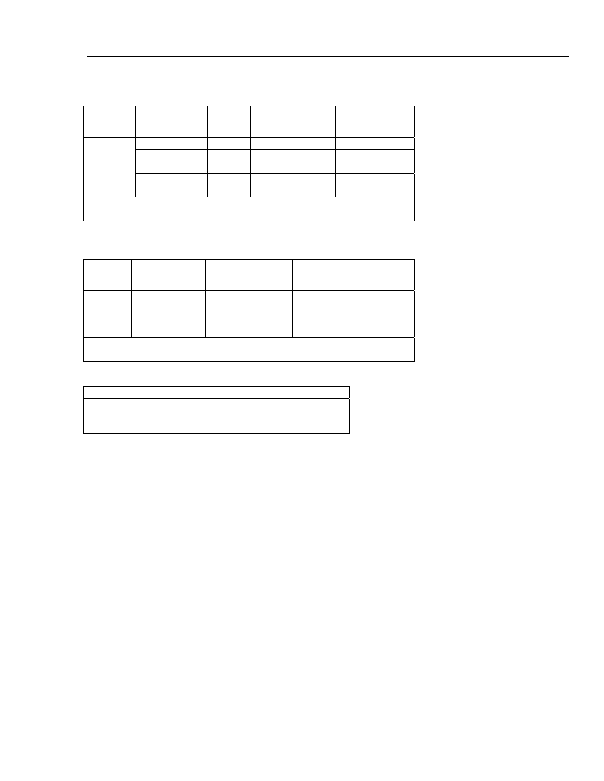
Continuity
Continuity Threshold............................................Selectable between 1 Ω and 1000 Ω
Test Current...........................................................1 mA
Response Time .....................................................300 samples/sec with audible tone
Accuracy is given as ± (% measurements + % of range)
Range
1000.0 Ω 0.002 + 0.01 0.008 + 0.02 0.01 + 0.02
24 Hour
(23 ±1 °C)
90 Days
(23 ±5 °C)
1 Year
(23 ±5 °C)
Temperature
Coefficient/ °C
Outside 18 to 28 °C
0.001 + 0.002
1-20
Page 31

Introduction and Specifications
Measurement Uncertainty 1
Diode Test
Test Current........................................................... 100 μA or 1 mA
Response Time ..................................................... 300 samples/sec with audible tone.
Accuracy is given as ± (% measurements + % of range)
Range
5.0000 V 0.002 + 0.002 0.008 + 0.002 0.01 + 0.002 0.001 + 0.002
10.0000 V 0.002 + 0.001 0.008 + 0.002 0.01 + 0.002 0.001 + 0.002
24 Hour
(23 ±1 °C)
90 Days
(23 ±5 °C)
1 Year
(23 ±5 °C)
Temperature
Coefficient/ °C
Outside 18 to 28 °C
Measurement Rates
Function Digits Setting
DC Volts, DC Current, and
Resistance
AC Voltage and AC Current
Frequency and Period
[1] Typical measurement rates with auto-zero off.
[2] Maximum measurement rates for 0.01 % of ac step. When dc input varies, additional settling delay is required.
[3] For remote operation or external trigger using default settling delay
[4] Settling delay = 0
[2]
6½ 100 NPLC 1.67 (2) s 0.6 (0.5) 0.6 (0.5)
6½ 10 NPLC 167 (200) ms 6 (5) 6 (5)
5½ 10 NPLC 16.7 (20) ms 60 (50) 60 (50)
5½ 0.2 NPLC 3 ms 300 300
6½ 3 Hz 0.14 0.14
6½ 20 Hz 1 1
6½ 200 Hz
6½ 200 Hz
6½ 1 s 1 1
5½ 100 ms 9.8 9.8
4½ 10 ms 80 80
Integration Time
60 Hz (50 Hz)
[3]
1.6 1.6
[4]
6 6
Measurements/Second
8845A 8846A
[1]
Measurement Uncertainty
The Meter's measurement uncertainties are expressed in the form ( % of reading + % of
range ). In addition to the reading error and range error, you may need to add additional
errors for certain operating conditions. If the Meter is operated outside the temperature
range specified, an additional temperature coefficient error must be applied. For dc
voltage, dc current, and resistance measurements, apply an additional reading-speed
error. For ac voltage and ac current measurements, apply an additional low frequency
error or crest factor error.
The "% of reading" error varies according to the input level on the selected range. This
error is expressed in percent of input measurement. The “% of range” error represents the
floor noise of the range and represents the lowest meaningful resolution for that range.
The following example shows the reading error applied to the Meter's 24-hour 10 Vdc
specification: 0.0013% of input + 0.0004% of range.
Assuming the Meter is set to the 10V range with an input voltage of 1 V, the
measurement uncertainty would be: +/- [(0.0013% x 1V) + (.0004% x 10V)].
Permissible High Value = 1 + 0.000053V = 1.000053 V
Permissible Low Value = 1 - 0.000053V = 0.999947 V
1-21
Page 32

8845A/8846A
Calibration Manual
Interpreting Accuracy Specifications
24
-Hour Accuracy
90
-Day and 1-Year Accuracy
Temperature Coefficients
The following sections provide a clearer understanding of specifications over time and
with temperature variations.
The 24
measurement range for short time intervals and within a stable environment. Short
accuracy is usually specified for a 24
The longer
-hour accuracy specification indicates the Meter's relative accuracy over its full
-term
-hour period and for a ±1 °C temperature range.
duration accuracy specifications are valid at the calibration temperature (Tcal)
±5 °C temperature range. These specifications include the initial calibration errors plus
the Meter's long
Accuracy is usually specified at the calibration temperature (T
-term drift errors.
cal) ±5 °C temperature
range. This is a common temperature range for many operating environments. Add
additional temperature coefficient errors to the accuracy specification if the Meter is
operated outside the ±5 °C temperature range (the specification is per °C).
Configuring for Highest Accuracy Measurements
The measurement configurations shown below assume that the Meter is in its power–on
or reset state. It is also assumed that auto-ranging is enabled to ensure proper full-scale
range selection.
DC Voltage, DC Current, and Resistance Measurements
Select NPLC and 100 (NPLCs) for highest instrument resolution and accuracy.
For the best dc voltage accuracy, set INPUT HIGH INPUT Z (impedance) to GOhm (for
the 100 mV, 1 V, and 10 V ranges).
For the best resistance measurement accuracy, use the 4
For 2
-wire ohms, dc voltage and dc current measurements, set AUTOZERO to ON to
remove thermal EMF and offset errors.
Zero the test lead resistance for 2
-wire and 4-wire ohms measurements and zero to
remove any interconnection offset for dc voltage measurements.
AC Voltage and AC Current Measurements:
Set the AC FILTER to 3 Hz: SLOW.
Frequency and Period Measurements:
Set the GATE TIME to 1 sec.
-wire ohms function (4W).
1-22
Page 33

Chapter 2
General Maintenance
Title Page
Introduction........................................................................................................ 2-3
Warranty Repairs and Shipping Information..................................................... 2-3
General Maintenance Information ..................................................................... 2-3
Required Equipment...................................................................................... 2-3
Power Requirements...................................................................................... 2-3
Static Safe Handling ...................................................................................... 2-3
Cleaning............................................................................................................. 2-4
Fuse Replacement .............................................................................................. 2-4
Line-Power Fuse............................................................................................ 2-4
Current-Input Fuses ....................................................................................... 2-5
If the Meter Does Not Turn On.......................................................................... 2-7
Display Tests...................................................................................................... 2-7
Disassembly Procedures .................................................................................... 2-7
General Disassembly ..................................................................................... 2-7
Main Chassis Disassembly ............................................................................ 2-8
Front Panel Disassembly ............................................................................... 2-8
Assembly Procedures......................................................................................... 2-8
2-1
Page 34

8845A/8846A
Calibration Manual
2-2
Page 35

General Maintenance
Introduction 2
Introduction
This chapter provides handling, cleaning, fuse replacement, disassembly, and assembly
instructions for the Meter.
Warranty Repairs and Shipping Information
If your meter is still under warranty, see the warranty information at the front of this
manual for instructions on returning the unit. A list of Fluke telephone numbers and the
website address can be found in the “How to Contact Fluke” section of Chapter 4.
General Maintenance Information
The following sections describe how to maintain the Meter.
Required Equipment
Equipment required for calibration, troubleshooting, and repair of the Meter is listed in
Table 3-1.
Power Requirements
To avoid electric shock, connect the Meter’s power cord to a
power receptacle with earth ground.
The Meter operates on power distribution standards found throughout the world, and
must be set up to operate on the correct line voltage power it. The Meter is packed ready
for use with a line voltage determined at the time of ordering. If the selected line voltage
does not match the power the Meter will be plugged into, then the Meter’s line voltage
setting must be changed and the line fuse possibly replaced. See the 8845A/8846A Users
Manual for information on switching the Meter’s line voltage.
If you have not already done so, plug the line cord into the connector on the rear of the
Meter.
Static Safe Handling
All integrated circuits, including surface mounted ICs, are susceptible to damage from
electrostatic discharge (ESD). Modern integrated circuit assemblies are more susceptible
to damage from ESD than ever before.
Integrated circuits today can be built with circuit lines less than one micron thick,
allowing more than a million transistors on a 1/4-inch square chip. These submicron
structures are sensitive to static voltages under 100 volts. This much voltage can be
generated on a dry day by simply moving your arm. A person can develop a charge of
2,000 volts by walking across a vinyl tile floor, and polyester clothing can easily generate
5,000 to 15,000 volts during movement against the wearer. These low voltage static
problems are often undetected, because a static charge must be in the 30,000 to 40,000
volt range before a person will feel a shock.
XW Warning
Most electronic components manufactured today can be degraded or destroyed by ESD.
While protection networks are used in CMOS devices, they can only reduce, not
eliminate, component susceptibility to ESD.
ESD may not cause an immediate failure in a component; a delayed failure or
"wounding" effect is caused when the semiconductor’s insulation layers or junctions are
2-3
Page 36

8845A/8846A
Calibration Manual
punctured. The static problem is thus complicated in that failure may occur anywhere
from two hours to six months after the initial damage.
Two failure modes are associated with ESD. First, a person who has acquired a static
charge can touch a component or assembly and cause a transient discharge to pass
through the device. The resulting current ruptures the junctions of a semiconductor. The
second failure mode does not require contact with another object. Simply exposing a
device to the electric field surrounding a charged object can destroy or degrade a
component. MOS devices can fail when exposed to static fields as low as 30 volts.
Observe the following rules for handling static-sensitive devices:
1. Handle all static-sensitive components in a static-safe work area.
Use grounded static-control table mats on all repair benches, and always wear a
grounded wrist strap. Handle boards by their nonconductive edges only. Store plastic,
vinyl, and Styrofoam objects outside the work area.
2. Store and transport all static-sensitive components and assemblies in static shielding
bags or containers.
Static-shielding bags and containers protect components and assemblies from direct static
discharge and external static fields. Store components in their original packages until they
are ready for use.
Cleaning
To avoid electric shock or damage to the Meter, never get water
inside the meter.
To avoid damaging the Meter’s housing, do not apply solvents
to the Meter.
If the Meter requires cleaning, wipe it down with a cloth lightly dampened with water or
a mild detergent. Do not use aromatic hydrocarbons, chlorinated solvents, or methanolbased fluids to wipe down the meter.
Fuse Replacement
The Meter employs fuses to protect both the line-power and current measurement inputs.
Line-Power Fuse
The Meter has a line-power fuse in series with the power supply. Table 2-1 indicates the
proper fuse for each of the four line voltage selections. This fuse is located on the rear
panel.
To replace this fuse:
XW Warning
W Caution
2-4
1. Unplug the power cord from the Meter and remove any test leads.
2. Remove the fuse holder by inserting a small screwdriver blade in the narrow recess to
the left of the fuse holder and pry to the right until the holder pops out, as shown in
Figure 2-1. The Meter is shipped with a replacement fuse of the same rating as the
fuse installed in the fuse block.
Page 37

General Maintenance
Fuse Replacement 2
3. Remove the fuse and replace with one rated appropriately for the selected line-power
voltage. See Table 2-1 for fuse ratings with specific line voltage.
4. Replace the selector block back into the fuse holder.
XW Warning
To avoid electric shock or fire, do not use makeshift fuses or
short-circuit the fuse holder. Use only Fluke fuses.
Table 2-1. Line Voltage to Fuse Rating
Line Voltage Selection Fuse Rating Fluke Part No.
100 0.25 A, 250 V (slow blow) 166306
120 0.25 A, 250 V (slow blow) 166306
220 0.125 A, 250 V (slow blow) 166488
240 0.125 A, 250 V (slow blow) 166488
120
Figure 2-1. Line Fuse Replacement
caw0201f.eps
Current-Input Fuses
The 100 mA and 10 A inputs are protected by user-replaceable fuses.
• The 100 mA input is protected by a fuse (A1F2) rated at 440 mA, 1000 V (fast
blow), 10,000 A minimum breaking capacity.
• The 10 A input is protected by a fuse (A1F1) rated at 11 A, 1000 V (fast blow),
10,000 A minimum breaking capacity.
W Warning
For protection against fire or arc flash, replace a blown fuse
only with one from Fluke.
2-5
Page 38

8845A/8846A
Calibration Manual
To test for a blown Current Input fuse:
1. With the Meter powered up, plug a test lead into the VΩGER connector.
If the fuse is good, the Meter will read less than 200 Ω. If the fuse is blown, the
Meter will read overload.
2. Remove the probe from the 100 mA connector and insert into the 10 A
connector.
If the fuse is good, the Meter will read less than 1 Ω. If the fuse is blown, the
Meter will read overload.
To replace the Current Input fuses:
1. Turn the Meter off, unplug the power cord from the Meter, and remove all test
leads.
2. Turn the Meter on its back.
3. Unscrew the retaining screw on the fuse access door, as depicted in Figure 2-2.
4. Remove the protective cover from the fuse holders by slightly depressing the
back edge of the cover to unlatch it from the printed circuit board. Pull up on the
back edge of the cover and remove it from the fuse compartment.
5. Remove the defective fuse and replace with one having the appropriate rating
(See table 4-1 for fuse ratings and Fluke part numbers).
6. Replace the protective cover by pushing it over the fuses while aligning the
catches with the holes in the printed circuit board. Press the cover down until the
catches engage the printed circuit board.
7. Replace the fuse door and secure it by tightening the retaining screw.
Fuses
A1 F1
A1 F2
Bottom front
left corner
2-6
Figure 2-2. Current Input Fuse Replacement
caw020.eps
Page 39

General Maintenance
If the Meter Does Not Turn On 2
If the Meter Does Not Turn On
Use the following steps to help solve problems encountered when turning on the Meter.
1. Verify the Meter’s power switch is in the “On” position.
2. Make sure that the power cord is firmly plugged into the power module on the rear of
the Meter.
3. Make sure the power source the Meter is plugged into is energized.
4. Ensure the Meter’s power line voltage is set to the proper value for your country. See
the “Fuse Replacement” section earlier in this chapter for instructions on changing
the Meter’s voltage setting.
5. Verify that the power-line fuse is good.
If these steps don’t solve the problem, then contact Fluke for more help. See the
“Contacting Fluke” section in Chapter 4 for contact information.
Display Tests
To test the pixels on the front panel display, use the following steps.
1. Press I.
2. Press the SYSTEM softkey.
3. Press the DISPLAY softkey.
All pixels of the display should be illuminated.
Disassembly Procedures
To avoid electric shock, disconnect the Meter from power
before removing the cover.
Only qualified service personnel should attempt servicing this
Meter.
To disassemble the Meter, a #2 Phillips screwdriver and small crescent wrench are
required. There are three sets of disassembly instructions: general, main chassis, and front
panel.
General Disassembly
To disassemble the Meter:
1. Turn off the power by turning off the mains power at the rear of the Meter and
removing the power cord. The front panel power key only puts the Meter in a powersave mode and does not remove mains power from the Meter.
XWWarning
2. Remove all cables from the Meter.
3. Remove the Meter bumpers by pulling from a corner and stretching the bumpers off
the Meter.
4. Remove the bail by rotating the handle upright to a 90° angle from the top of the
Meter and pull bail out from the sides of the Meter.
5. Remove the top cover by removing the four screws on the bottom of the chassis, and
slide the cover towards the back of the Meter.
2-7
Page 40

8845A/8846A
Calibration Manual
Main Chassis Disassembly
6. Remove the wedges from the front and rear input modules by rotating the top toward
the chassis middle and pulling up. See Figure 4-1.
7. Remove both sets of screws holding the front panel to the chassis (8-32 pan head and
6-32 flat head undercut). See Figure 4-1.
8. Gently remove the front panel by pulling it forward and set it aside.
9. Remove the plastic handle caps from the chassis sides by rotating the front slightly
inward and pulling forward.
To disassemble the Meter’s main chassis:
1. Carefully remove the transformer connectors from the main board.
2. Carefully remove the screws that hold the transformer and its bracket to the chassis
while holding the transformer so that it cannot drop on the circuits.
3. Carefully lift the transformer out of the chassis and place the transformer behind the
instrument with the power module leads still attached.
4. Remove the jackscrews for the RS-232 and IEEE488 connectors to the chassis.
5. Remove the screws holding the main circuit board to the chassis (three 6-32 pan-head
screws).
6. Remove the main circuit board.
Front Panel Disassembly
To disassemble the Meter’s front panel:
1. Remove the one 6-32 pan head and two 6-32 flat head undercut screws holding the
display shield to the rest of the front panel assembly and remove the shield.
2. Remove the thread-forming screw holding the front panel shield to the front panel
and remove the shield.
3. Remove the three thread-forming screws from the keypad assembly and remove
display module.
Assembly Procedures
To assemble the three parts of the Meter, follow the disassembly instructions in reverse
order.
2-8
Page 41

Chapter 3
Performance Test and Calibration
Title Page
Introduction........................................................................................................ 3-3
Required Equipment .......................................................................................... 3-3
Test Considerations............................................................................................ 3-5
Performance Tests.............................................................................................. 3-5
Volts DC Verification.................................................................................... 3-5
Volts AC and Frequency Verification ........................................................... 3-8
4-Wire Ohms Verification............................................................................. 3-12
2-Wire Ohms Verification............................................................................. 3-14
2X4 Test Lead Verification Steps ................................................................. 3-16
Rear Panel Terminal Verification Steps ........................................................ 3-16
Capacitance Verification Steps (8846A only) ............................................... 3-19
DC Current Verification Steps ...................................................................... 3-20
AC Current Verification Steps ...................................................................... 3-23
Adjustment (Calibration) ................................................................................... 3-25
Unlocking the Meter for Front-Panel Adjustments (Calibration).................. 3-25
Unlocking the Meter for Adjustments Over a Remote Interface................... 3-26
Changing the Calibration Password .............................................................. 3-26
Resetting the Calibration Password............................................................... 3-26
Equipment for Calibration............................................................................. 3-27
Adjustment Process ....................................................................................... 3-27
Aborting a Calibration Process...................................................................... 3-33
Sample Adjustment Program......................................................................... 3-33
3-1
Page 42

8845A/8846A
Calibration Manual
3-2
Page 43

Performance Test and Calibration
Introduction 3
Introduction
This chapter of the Calibration Manual provides performance tests to verify the Meter is
operating within published specifications as well as a complete calibration procedure.
The performance test and, if necessary, the calibration procedure can be performed both
periodically and after service or repair.
The performance tests can be used as an acceptance test upon receipt of the Meter. Use
the 90-day specifications when performing an acceptance test after performing a
calibration.
Required Equipment
Table 3-1 lists the equipment required for performance testing and calibration of the
Meter.
Table 3-1. Required Test Equipment
Function Instrument Type Model Comments
Volts dc
Volts ac
Frequency
Standard Fluke 5520A Must be characterized with 8508A
8½ digit meter Fluke 8508A Used to characterize the 5520A
4-wire short Fluke low thermal 4-wire
short or equivalent
Alternate standard Fluke 5720A
Standard Fluke 5520A Must be characterized with 8508A
8½ digit meter Fluke 8508A Used to characterize the 5520A.
4-wire short Fluke low thermal 4-wire
short or equivalent
Alternate standard Fluke 5720A
Standard Fluke 5520A
Alternate standard Fluke 5520A with any
scope option
Alternate standard Function generator Specifications include0.075 %
Fluke PN 2653346
Note: TURs <4:1 at 1 V, 10 V, and
100 V at 20 kHz
Fluke PN 2653346
frequency accuracy from 3 – 40 Hz
and 0.0025 % accuracy for
frequencies up to 1 MHz
3-3
Page 44

8845A/8846A
Calibration Manual
Function Instrument Type Model Comments
Table 3-1. Required Test Equipment (cont.)
Ohms
Capacitance
(8846A only)
Current dc
Standard Fluke 5520A Must be characterized with 8508A
8½ digit meter Fluke 8508A Used to characterize the 5520A
4-wire short Fluke low thermal 4-wire
short or equivalent
Alternate standard Fluke 5720A or equivalent
Alternate standard
resistor
Standard Fluke 5520A TURS <4:1 at 1 nF, 10 nF, 100 μF,
Alternate
standards
Standard Fluke 5520A Must be characterized with 8508A
8½ digit meter Fluke 8508A Only used to characterize the
Alternate standard Fluke 5720A with Fluke
Fluke 8508A-7000K
1 Gohm resistor or
equivalent (better than
±0.35 % maximum
uncertainty)
1 nF, 10 nF, 100 nF, 1 μF,
10 μF, 100 μF, 1 mF,
10 mF, and 100 mF
standards
5725A
Fluke PN 2653346
Used for calibrating/verifying 1 GΩ
range in the 8846A when a 5520A
is not available.
1 mF, and 10 mF.
Standards must be ±0.25 % and
rated for at least 5 V
5520A
Note: TUR <4 at 10 A
Current ac
Cables
Standard Fluke 5520A Must be characterized with 8508A
8½ digit meter Fluke 8508A Only used to characterize the
5520A or 5720A
Alternate standard Fluke 5720A with Fluke
5725A
To reduce the possibility of inducing errors with ac signals picked up by the test
leads, use short, shielded twisted-pair PTFE-insulated test cables between the test
equipment and the Meter. Fluke makes a 2 foot (PN 738716) and 4 foot (PN 738724)
PTFE insulated test cable for this purpose.
Fluke USB to RS232 cable (PN 2675479) or Fluke IEEE 488 cable (2 meter, PN
708297)
TUR at 1 A at 5 kHz < 4:1. Must
characterize with 8508A at 100 μA
at 5 kHz. 100 μA, 1 mA, 10 mA, 100
mA, 1 A and 2 A at 10 kHz.
3-4
Page 45

Performance Test and Calibration
Test Considerations 3
Test Considerations
For optimum performance, all test procedures should comply with the following
recommendations:
• Assure the calibration ambient temperature (T
28 °C. Ideally the calibration should be performed at 23 °C ±2 °C.
• Assure ambient relative humidity is less than 80%.
• Allow a 60-minute warm-up period.
• Use shielded twisted-pair PTFE-insulated cables to reduce settling and noise
errors.
• Keep all input cables as short as possible.
• Ensure that the calibration standards and test procedures used do not introduce
additional errors.
Ideally, the standards used to verify and adjust the Meter should be four
times more accurate than each full-scale error specification of the Meter.
• User Fluke’s low thermal 4-Wire short for all voltages and ohmic shorts. See
Table 3-1 for Fluke part number..
Performance Tests
The following performance tests are provided to ensure that the Meter is in proper
operating condition. If the Meter fails any of the performance tests, calibration
adjustment and/or repair is needed. The performance test works best if executed in the
sequence shown in Table 3-2.
cal) is stable and between 18 °C and
Note
Each of the measurements listed in the following tests assumes the Meter is being tested
after a one-hour warm-up in an environment with an ambient temperature of 18 to 28ºC
and a relative humidity of less than 80%.
Volts DC Verification
Connect the Meter to the test equipment as shown in Figure 3-1 and, depending on which
meter you are calibrating, apply the voltages listed in Table 3-2 or Table 3-3. Verification
forms can be found in Appendix A which can be copied and used to record each meter
reading.
For the zero (0) V tests, use the 4-wire short to short the Hi/Lo and Sense
inputs.
Note
3-5
Page 46

8845A/8846A
Calibration Manual
6-1/2 DIGIT PRECISION MULTIMETER
8846A
+1.000002
F1 F2 F3 F4 F5
BACK
DCV
DCI ACI
: OFF
ACV
FREQ
TEMP
PERIOD
STBY
OPR
789
456
123
+
0•
/
: OFF
EX GRD
RANGE
OUT
TRIG
TRIG
ANALYZE
ZERO
SCOPE EXGRD MENU
EARTH
V
INPUT SENSE
V
2W/4W
HI
1000V CAT I
600V CAT II
LO
FUSED
100
mA
INPUT SENSE
V
4
HI
FUSED
1V
FUSED
REAR
5520A
NORMAL AUX
V, , ,
RTD
A, -SENSE,
HI
FUSED
LO
GUARD
20V PK MAX
W
FRONT
HI
300V
LO
10 A
CALIBRATOR
AUX V
20A
20V PK MAX
TC
A.
SCOPE
EX SNS
2W/4W
1000V CAT I
600V CAT II
LO
100
mA
4
W
HI
300V
LO
1V
10 A
FRONT
REAR
NC
Figure 3-1. DC Volts Test Equipment Setup with 5520A
INSTR
SETUP
MEAS
SETUP
μ
m
npW
k
M
SHIFT
MEMORY
PREV
dBm sec
VHz
ENTER
5720A CalibratorUUT
OUTPUT
V A
HI
LO
HI
AUX
CURRENT
F
CA
F
SENSE
V
WIDEBAND
HI
LO
GUARD
GROUND
caw023.eps
3-6
Table 3-2. 8846A DC Volts Verification Steps
Nominal
Input (V)
Range
90-day Test Limits 1-year Test Limits
High Low High Low
0 0.100 3.5 μV -3.5 μV 3.5 μV -3.5 μV
100.0 mV
-100.0 mV
[1]
0.100 100.006 mV 99.994 mV 100.0072 mV 99.9928 mV
[1]
0.100 -99.994 Mv -100.006 mV -99.9928 mV -100.0072 mV
0 V 1 7.0 μV -7.0 μV 7.0 μV -7.0 μV
[1]
1 V
1 1.000025 V 0.999975 V 1.000032 V 0.999968 V
[1]
-1 V
1 -0.999975 V -1.000025 V -0.999968 V -1.000032 V
0 V 10 50.0 μV -50.0 μV 50.0 μV -50.0 μV
Page 47

Performance Test and Calibration
Table 3-2. 8846A DC Volts Verification Steps (cont.)
Performance Tests 3
Nominal
Input (V)
[1]
5 V
10 5.000140 V 4.999860 V 5.000170 V 4.999830 V
[1]
-5 V
10 -4.999860 V -5.000140 V -4.999830 V -5.000170 V
[1]
10 V
10 10.000230 V 9.999770 V 10.000290 V 9.999710 V
[1]
-10 V
10 -9.999770 V -10.000230 V -9.999710 V -10.000290 V
Range
90-day Test Limits 1-year Test Limits
High Low High Low
0 V 100 600.0 μV -600.0 μV 600.0 μV -600.0 μV
[1]
100 V
100 100.0033 V 99.9967 V 100.0044 V 99.9956 V
[1]
-100 V
100 -99.9967 V -100.0033 V -99.9956 V -100.0044 V
0 V 1000 10.0 mV -10.0 mV 10.0 mV -10.0 mV
[1]
1 kV
1000 1000.0410 V 999.9590 V 1000.0510 V 999.9490 V
[1]
-1 kV
1000 -999.9590 V -1000.0410 V -999.9490 V -1000.0510 V
[1] 5520A must be used with 8508A to obtain suitable test uncertainty ratio.
Table 3-3. 8845A DC Volts Verification Steps
Nominal
Input (V)
Range
90-day Test Limits 1-year Test Limits
High Low High Low
0 V 0.100 3.5 μV -3.5 μV 3.5 μV -3.5 μV
100.0 mV
-100.0 mV
[1]
0.100 100.0075 mV 99.9925 mV 100.0085 mV 99.9915 mV
[1]
0.100 -99.9925 mV -100.0075 mV -99.9915 mV -100.0085 mV
0 V 1 7.0 μV -7.0 μV 7.0 μV -7.0 μV
[1]
1 V
1 1.000037 V 999.963 mV 1.000047 V 999.953 mV
[1]
-1 V
1 -999.963 mV -1.000037 V -999.953 mV -1.000047 V
0 V 10 50.0 μV -50.0 μV 50.0 μV -50.0 μV
[1]
5 V
10 5.00015 V 4.99985 V 5.000225 V 4.999775 V
[1]
-5 V
10 -4.99985 V -5.00015 V -4.999775 V -5.000225 V
[1]
10 V
10 10.00025 V 9.99975 V 10.0004 V 9.9996 V
-10 V 10 -9.99975 V -10.00025 V -9.9996 V -10.0004 V
0 V 100 600.0 μV -600.0 μV 600.0 μV -600.0 μV
100 V 100 100.0041 V 99.9959 V 100.0051 V 99.9949 V
-100 V 100 -99.9959 V -100.0041 V -99.9949 V -100.0051 V
0 V 1000 10.0 mV -10.0 mV 10.0 mV -10.0 mV
1 kV 1000 1.000045 kV 999.955E+0 1.000055 kV 999.945 V
-1 kV 1000 -999.955 V -1.000045 kV -999.945 V -1.000055 kV
[1] 5520A must be used with 8508A to obtain suitable test uncertainty ratio.
3-7
Page 48

8845A/8846A
Calibration Manual
Volts AC and Frequency Verification
Connect the Meter to the test equipment as shown in Figure 3-2 and, depending on which
meter you are calibrating, apply the voltage listed in Table 3-4 or Table 3-5. Verification
forms can be found in Appendix A which can be copied and used to record each meter
reading.
6-1/2 DIGIT PRECISION MULTIMETER
8846A
0.999944
F1 F2 F3 F4 F5
BACK
DCV
DCI ACI
: OFF
ACV
FREQ
TEMP
PERIOD
STBY
OPR
789
456
123
+
0•
/
: OFF
EX GRD
RANGE
OUT
TRIG
ZERO
SCOPE EXGRD MENU
EARTH
INPUT SENSE
V
2W/4W
HI
1000V CAT I
600V CAT II
LO
FUSED
100
mA
INPUT SENSE
V
4
HI
FUSED
LO
1V
FUSED
REAR
5520A
NORMAL AUX
V, , ,
RTD
A, -SENSE,
HI
FUSED
LO
GUARD
20V PK MAX
W
300V
FRONT
CALIBRATOR
A.
HI
LO
10 A
SCOPE
AUX V
20A
20V PK MAX
TC
EX SNS
2W/4W
1000V CAT I
600V CAT II
100
mA
4
W
HI
300V
LO
1V
10 A
FRONT
REAR
NC
Figure 3-2. AC Volts Test Equipment Setup with 5520A
TRIG
ANALYZE
V
μ
npW
SHIFT
INSTR
SETUP
MEAS
SETUP
m
k
M
MEMORY
PREV
dBm sec
VHz
ENTER
5720A CalibratorUUT
OUTPUT
V A
HI
LO
HI
AUX
CURRENT
F
CA
F
SENSE
V
WIDEBAND
HI
LO
GUARD
GROUND
caw024.eps
3-8
Page 49

Performance Test and Calibration
Table 3-4. 8846A AC Volts Verification Steps
Performance Tests 3
Nominal Input 90-day Test Limits 1-year Test Limits
Range
Ampl. Freq.
100.0 mV
[1]
10 Hz 0.100 100.09 mV 99.91 mV 100.1 mV 99.9 mV
High Low High Low
100.0 mV 20 kHz 0.100 100.09 mV 99.91 mV 100.1 mV 99.9 mV
100.0 mV 50 kHz 0.100 100.16 mV 99.84 mV 100.17 mV 99.83 mV
100.0 mV 100 kHz 0.100 100.68 mV 99.32 mV 100.68 mV 99.32 mV
100.0 mV 300 kHz 0.100 104.5 mV 95.5 mV 104.5 mV 95.5 mV
[1]
1 V
10 Hz 1 1.0008 V 999.2 mV 1.0009 V 999.1 mV
1 V 20 kHz 1 1.0008 V 999.2 mV 1.0009 V 999.1 mV
1 V 50 kHz 1 1.0016 V 998.4 mV 1.0017 V 998.3 mV
1 V 100 kHz 1 1.0068 V 993.2 mV 1.0068 V 993.2 mV
1 V 300 kHz 1 1.045 V 955.0 mV 1.045 V 955.0 mV
[1]
10 V
10 Hz 10 10.008 V 9.992 V 10.009 V 9.991 V
[1]
10 V
20 kHz 10 10.008 V 9.992 V 10.009 V 9.991 V
10 V 50 kHz 10 10.016 V 9.984 V 10.017 V 9.983 V
10 V 100 kHz 10 10.068 V 9.932 V 10.068 V 9.932 V
3 V 300 kHz 10 3.17 V 2.83 V 3.17 V 2.83 V
100 V 45 Hz 100 100.08 V 99.92 V 100.09 V 99.91 V
[1]
100 V
20 kHz 100 100.08 V 99.92 V 100.09 V 99.91 V
100 V 50 kHz 100 100.16 V 99.84 V 100.17 V 99.83 V
[1]
100 V
100 kHz 100 100.68 V 99.32 V 100.68 V 99.32 V
1000 V 45 Hz 1000 1000.800 999.200 1.0009 kV 999.1 V
1000 V 1 kHz 1000 1000.800 999.200 1.0009 kV 999.1 V
[1]
1000 V
10 kHz 1000 1000.800 999.200 1.0009 kV 999.1 V
320 V 20 kHz 1000 320.460 319.540 320.492 V 319.508 V
320 V 50 kHz 1000 320.852 V 319.148 V 320.884 V 319.116 V
320 V 100 kHz 1000 322.72 V 317.28 V 322.72 V 317.28 V
[1] 5520A must be used with 8508A to obtain suitable test uncertainty ratio.
3-9
Page 50

8845A/8846A
Calibration Manual
Table 3-5. 8845A AC Volts Verification Steps
Nominal Input 90-day Test Limits 1-year Test Limits
Range
Ampl. Freq.
100.0 mV
[1]
10 Hz 0.100 100.09 mV 99.91 mV 100.1 mV 99.9 mV
High Low High Low
100.0 mV 20 kHz 0.100 100.09 mV 99.91 mV 100.1 mV 99.9 mV
100.0 mV 50 kHz 0.100 100.16 mV 99.84 mV 100.17 mV 99.83 mV
100.0 mV 100 kHz 0.100 100.68 mV 99.32 mV 100.68 mV 99.32 mV
100.0 mV 300 kHz 0.100 104.5 mV 95.5 mV 104.5 mV 95.5 mV
[1]
1 V
10 Hz 1 1.0008 V 999.2 mV 1.0009 V 999.1 mV
1 V 20 kHz 1 1.0008 V 999.2 mV 1.0009 V 999.1 mV
1 V 50 kHz 1 1.0016 V 998.4 mV 1.0017 V 998.3 mV
1 V 100 kHz 1 1.0068 V 993.2 mV 1.0068 V 993.2 mV
1 V 300 kHz 1 1.045 V 955.0 mV 1.045 V 955.0 mV
[1]
10 V
10 Hz 10 10.008 V 9.992 V 10.009 V 9.991 V
[1]
10 V
20 kHz 10 10.008 V 9.992 V 10.009 V 9.991 V
10 V 50 kHz 10 10.016 V 9.984 V 10.017 V 9.983 V
10 V 100 kHz 10 10.068 V 9.932 V 10.068 V 9.932 V
3 V 300 kHz 10 3.17 V 2.83 V 3.17 V 2.83 V
100 V 45 Hz 100 100.08 V 99.92 V 100.09 V 99.91 V
[1]
100 V
20 kHz 100 100.08 V 99.92 V 100.09 V 99.91 V
100 V 50 kHz 100 100.16 V 99.84 V 100.17 V 99.83 V
[1]
100 V
100 kHz 100 100.68 V 99.32 V 100.68 V 99.32 V
750 V 45 Hz 750 750.600 749.400 750.675 V 749.325 V
750 V 1 kHz 750 750.600 749.400 750.675 V 749.325 V
750 V 10 kHz 750 750.600 749.400 750.675 V 749.325 V
320 V 20 kHz 750 320.385 319.615 320.417 V 319.583 V
320 V 50 kHz 750 320.727 V 319.273 V 320.759 V 319.241 V
320 V 100 kHz 750 322.52 V 317.48 V 322.52 V 317.48 V
3-10
[1] 5520A must be used with 8508A to obtain suitable test uncertainty ratio.
Page 51

Performance Test and Calibration
Table 3-6. 8845A/8846A AC Volts Frequency Verification Steps
Nominal Input 90-day Test Limits 1-year Test Limits
Ampl. Freq. High Low High Low
1 V 10 Hz 10.00300 Hz 9.99700 Hz 10.00300 Hz 9.99700 Hz
1 V 40 Hz 40.0040 Hz 39.9960 Hz 40.01200 Hz 39.98800 Hz
100 mV 300 kHz 300.030 kHz 29.99700 kHz 300.0300 kHz 29.99700 kHz
100 mV 1 MHz
[1] 8846A Only.
[1]
1.000100 MHz 999.9000 kHz 1.0001000 MHz 999.9000 kHz
Performance Tests 3
3-11
Page 52

8845A/8846A
Calibration Manual
4-Wire Ohms Verification
Connect the Meter to the test equipment as shown in Figure 3-3 and, depending on which
meter you are calibrating, apply the resistance listed in Table 3-7 or Table 3-8.
Verification forms can be found in Appendix A which can be copied and used to record
each meter reading.
Note
For zero (0) ohms tests, use the 4-wire short to short the Hi/Lo and Sense
inputs.
INPUT SENSE
V
2W/4W
HI
1000V CAT I
600V CAT II
LO
FUSED
100
mA
INPUT SENSE
V
4
HI
FUSED
LO
1V
FUSED
REAR
5520A
NORMAL AUX
V, , ,
RTD
A, -SENSE,
HI
FUSED
LO
GUARD
20V PK MAX
NC
W
FUSED
FRONT
FUSED
HI
300V
LO
10 A
CALIBRATOR
AUX V
20A
20V PK MAX
TC
SCOPE
2W/4W
1000V CAT I
600V CAT II
100
mA
4
W
HI
300V
LO
1V
10 A
FRONT
REAR
6-1/2 DIGIT PRECISION MULTIMETER
8846A
F1 F2 F3 F4 F5
BACK
DCV
DCI ACI
RANGE
OUT
TRIG
ACV
FREQ
PERIOD
TEMP
STBY
OPR
789
456
123
+
0•
/
EARTH
NC
Figure 3-3. 4-Wire Ohms Test Equipment Setup
4
w
TRIG
SETUP
ANALYZE
ZERO
SETUP
SCOPE EXGRD MENU
μ
m
npW
k
M
SHIFT
NC
INSTR
MEAS
dBm sec
HI
LO
HI
CURRENT
MEMORY
PREV
VHz
F
CA
F
ENTER
5720A CalibratorUUT
OUTPUT
SENSE
V A
AUX
GUARD
NC
V
WIDEBAND
HI
LO
GROUND
caw025.eps
3-12
Page 53

Performance Test and Calibration
Table 3-7. 8846A 4-Wire Ohms Verification Steps
Performance Tests 3
Nominal
Input
[1]
0 Ω
10 3.0 mΩ 0 Ω 3.0 mΩ 0 Ω
[1]
10 Ω
10 10.00380 Ω 9.99620 Ω 10.00400 Ω 9.99600 Ω
[2]
0 Ω
100 4.0 mΩ 0 Ω 4.0 mΩ 0 Ω
[1]
100 Ω
100 100.0120 Ω 99.9880 Ω 100.01400 Ω 99.98600 Ω
Range
90-day Test Limits 1-year Test Limits
High Low High Low
0 Ω 1000 10.0 mΩ 0 Ω 10.0 mΩ 0 Ω
1 kΩ 1000 1000.090 Ω 999.910 1.00011000 kΩ 999.89000
0 Ω 10000 100.0 mΩ 0 Ω 100.0 mΩ 0 Ω
10 kΩ 10000 10.00090 kΩ 9999.10 1.000110 kΩ 9998.90
0 Ω 100000 1.000000 0 Ω 1.000000 0 Ω
100 kΩ 100000 100.0090 kΩ 99991.0 10.00110 kΩ 99989.0
[1] 5520A must be used with 8508A to obtain suitable test uncertainty ratio.
Table 3-8. 8845A 4-Wire Ohms Verification Steps
Nominal
Input
[1]
0 Ω
100 4.0 mΩ 0 Ω 4.0 mΩ 0 Ω
[1]
100 Ω
100 100.0120 Ω 99.9880 Ω 100.01400 Ω 99.98600 Ω
Range
90-day Test Limits 1-year Test Limits
High Low High Low
0 Ω 1000 10.0 mΩ 0 Ω 10.0 mΩ 0 Ω
1 kΩ 1000 1.00009 kΩ 999.910 Ω 1.000110 kΩ 999.89000 Ω
0 Ω 10000 100.0 mΩ 0 Ω 100.0 mΩ 0 Ω
10 kΩ 10000 10.00090 kΩ 9999.10 Ω 10.00110 kΩ 9998.90 Ω
0 Ω 100000 1.000000 Ω 0 Ω 1.000000 Ω 0 Ω
100 kΩ 100000 100.0090 kΩ 99.9910 kΩ 100.0110 kΩ 99.9890 kΩ
[1] 5520A must be used with 8508A to obtain suitable test uncertainty ratio.
3-13
Page 54

8845A/8846A
Calibration Manual
2-Wire Ohms Verification
Connect the Meter to the test equipment as shown in Figure 3-4 and, depending on which
meter you are calibrating, apply the resistance listed in Table 3-9 or Table 3-10.
Verification forms can be found in Appendix A which can be copied and used to record
each meter reading.
Note
For zero (0) ohms tests, use the 4-wire short to short the Hi/Lo and Sense
inputs.
2W/4W
HI
1000V CAT I
600V CAT II
LO
100
mA
V
6-1/2 DIGIT PRECISION MULTIMETER
8846A
F1 F2 F3 F4 F5
BACK
DCV
DCI ACI
RANGE
OUT
TRIG
ACV
FREQ
TEMP
PERIOD
STBY
OPR
789
456
123
+
0•
/
EARTH
INPUT SENSE
1V
FUSED
FRONT
REAR
4
W
HI
300V
LO
10 A
INPUT SENSE
V
2W/4W
HI
1000V CAT I
FUSED
600V CAT II
LO
FUSED
100
mA
REAR
NORMAL AUX
V, , ,
RTD
FUSED
GUARD
20V PK MAX
1V
FRONT
5520A
A, -SENSE,
HI
LO
4
W
300V
CALIBRATOR
HI
LO
10 A
SCOPE
AUX V
20A
20V PK MAX
TC
NC
Figure 3-4. 2-Wire Ohms Test Equipment Setup
TRIG
SETUP
ANALYZE
ZERO
SETUP
SCOPE EXGRD MENU
μ
m
npW
k
M
SHIFT
NC
INSTR
MEAS
dBm sec
HI
LO
MEMORY
PREV
VHz
F
CA
F
ENTER
5720A CalibratorUUT
OUTPUT
V A
HI
AUX
CURRENT
NCNC
SENSE
V
GUARD
HI
LO
WIDEBAND
GROUND
caw026.eps
3-14
Page 55

Performance Test and Calibration
Table 3-9. 8846A 2-Wire Ohms Verification Steps
Nominal
Input
[2] [3]
0 Ω
100 4.0 mΩ 0 Ω 4.0 mΩ 0 Ω
[2] [3]
100 Ω
100 100.01200 Ω 99.988 Ω 100.0140 Ω 99.9860 Ω
Range
90-day Test Limits
High Low High Low
0 Ω 1000 10.0 mΩ 0 Ω 10.0 mΩ 0 Ω
1.000 kΩ 1000 1.00009 kΩ 999.910 Ω 1.000110 kΩ 999.890 Ω
0 Ω 10000 0.100000 Ω 0 Ω 0.100000 Ω 0 Ω
10.000 kΩ 10000 10.00090 kΩ 9.99910 kΩ 10.00110 kΩ 9.99890 kΩ
0 Ω 100000 1.000000 Ω 0 Ω 1.000000 Ω 0 Ω
100.000 kΩ 100000 100.0090 kΩ 99.9910 kΩ 100.0110 kΩ 99.9890 kΩ
0 Ω 1000000 10.00000 Ω 0 Ω 10.00000 Ω 0 Ω
1.00000 MΩ
[2]
0 Ω
10.0000 MΩ
[2]
1000000 1.000090 MΩ 0.999910 MΩ 1.000110 MΩ 0.999890 MΩ
10000000 100.0000 Ω 0 Ω 100.0000 Ω 0 Ω
[2]
10000000 10.00210 MΩ 9.99790 MΩ 10.00410 MΩ 9.995900 MΩ
[1]
1-year Test Limits
Performance Tests 3
[1]
0 100000000 10.00000 kΩ 0 Ω 10.00000 kΩ 0 Ω
100.000 MΩ 100000000 100.8100 MΩ 99.1900 MΩ 100.8100 MΩ 99.1900 MΩ
0 1000000000 100.0000 kΩ 0 Ω 1.000000 MΩ 0 Ω
1.00000 GΩ
[2]
1000000000 1.015100 GΩ 0.984900 GΩ 1.020100 GΩ 0.979900 GΩ
[1] Zero Meter before each measurement.
[2] 5520A must be used with 8508A to obtain suitable test uncertainty ratio.
[3] Optional test.
Table 3-10. 8845A 2-Wire Ohms Verification Steps
[1]
Range
Input
[2] [3]
0
100 4.0 mΩ 0 Ω 4.0 mΩ 0 Ω
[2] [3]
100 Ω
100 100.01200 Ω 99.9880 kΩ 100.0140 Ω 99.9860 Ω
90-day Test Limits
High Low High Low
1-year Test Limits
[1]
Nominal
0 1000 10.0 mΩ 0 Ω 10.0 mΩ 0 Ω
1.000 kΩ 1000 1.000090 kΩ 0.99991 kΩ 1.000110 kΩ 0.999890 kΩ
0 Ω 10000 0.100000 Ω 0 Ω 0.100000 Ω 0 Ω
10.000 kΩ 10000 10.00090 kΩ 9.99910 kΩ 10.00110 kΩ 9.99890 kΩ
0 Ω 100000 1.000000 Ω 0 Ω 1.000000 Ω 0 Ω
3-15
Page 56

8845A/8846A
Calibration Manual
100.000 kΩ 100000 100.0090 kΩ 99.9910 kΩ 100.0110 kΩ 99.9890 kΩ
0 Ω 1000000 10.00000 Ω 0 Ω 10.00000 Ω 0 Ω
1.00000 MΩ
[1]
0
10000000 100.0000 Ω 0 Ω 100.0000 Ω 0 Ω
10.0000 MΩ
0 100000000 10000.00 Ω 0 Ω 10000.00 Ω 0 Ω
100.0000 MΩ 100000000 100.8100 MΩ 99.19000 MΩ 100.8100 MΩ 99.19000 MΩ
[1] Zero Meter before each measurement.
[2]
5520A must be used with 8508A to obtain suitable test uncertainty ratio.
Input
Table 3-10. 8845A 2-Wire Ohms Verification Steps (cont.)
Range
[2]
1000000 1.000090 MΩ 0.999910 MΩ 1.000110 MΩ 0.999890 MΩ
[2]
10000000 10.002100 MΩ 9.997900 MΩ 10.004100 MΩ 9.995900 MΩ
90-day Test Limits
High Low High Low
[1]
1-year Test Limits
[1]
Nominal
[3] Optional test.
2X4 Test Lead Verification Steps
This optional test verifies Meter operation with the TL2X4W-PT 2X4-Wire Test Leads.
To verify 2X4 Test Lead performance:
1. Plug the TL2X4W-PT 2X4-Wire Test Leads into the HI and LO terminals of the
Meter (correct orientation is with the bump down)
2. Press N.
3. If not already highlighted, press the 2X4WIRE soft key.
4. Connect the probe tips together to get the lowest reading.
The Meter should read under 3 milliohms. If the Meter reads above 3 milliohms, clean
off the probes with a damp cloth and repeat step 4 above.
If the leads are damaged, replace them.
Rear Panel Terminal Verification Steps
This optional test verifies Meter operation through the rear-panel input terminals.
After connecting the Meter to the test equipment as shown in Figure 3-5, apply the
nominal values listed in Table 3-11 or Table 3-12, depending on which meter you are
calibrating.
Note
3-16
Page 57

Performance Test and Calibration
Performance Tests 3
100 mA
INPUT SENSE
V
HI
1000V CAT I
600V CAT II
LO
FUSED
1
/4A SLOW FUSE,100/120 VAC
1
/8A SLOW FUSE, 220/240 VAC
IEEE488
WARNING:
TO AVOID ELECTRIC SHOCK
GROUNDING CONNECTOR
IN POWER CORD
MUST BE CONNECTED
5520A
NORMAL AUX
V, , ,
RTD
A, -SENSE,
HI
LO
GUARD
20V PK MAX
47 - 440 Hz
25 VA MAX
RS-232
NO INTERNAL USER SERVICEABLE PARTS
REFER SERVICE TO QUALIFIED SERVICE PERSONNEL
CALIBRATOR
SCOPE
AUX V
OUT
TRIG
20A
20V PK MAX
TC
CAUTION:
FOR FIRE PROTECTION REPLACE
ONLY WITH A 250V FUSE
AS STATED IN MANUAL.
CAL STICKER
LAN
TRIG I/O
STBY
OPR
789
456
123
+
0•
/
INPUT SENSE
V
HI
1000V CAT I
600V CAT II
LO
FUSED
100 mA
SERIAL TAG
SCOPE EXGRD MENU
EARTH
UUT
4
W
HI
300V
1V
FRONT
N10140
FLUKE CORPORATION
MADE IN USA
www.fluke.com
LO
NC
NC
NC
Figure 3-5. Rear-Panel Terminals Equipment Setup
1V
FLUKE CORPORATION
www.fluke.com
μ
m
npW
k
M
SHIFT
4
W
HI
300V
LO
N10140
MADE IN USA
PREV
dBm sec
VHz
F
CA
F
ENTER
5720A Calibrator
OUTPUT
SENSE
V A
V
HI
LO
HI
AUX
CURRENT
GUARD
NC
WIDEBAND
HI
LO
GROUND
caw027.eps
3-17
Page 58

8845A/8846A
Calibration Manual
Table 3-11. 8846A Rear-Panel Terminal Verification Steps (Optional Test)
Nominal
Input
10 V dc
Range
[1]
10 V 10.00023 V 9.99977 V 10.00029 V 9.99971 V
90-day Test Limits 1-year Test Limits
High Low High Low
1000 Ω 4-W 1 kΩ 1000.09 Ω 999.91 Ω 1000.11 Ω 999.89 Ω
100 mA 100 mA 0.100035 A 0.099965 A 0.100055 A 0.099945 A
[1] 5520A must be used with 8508A to obtain suitable test uncertainty ratio.
Table 3-12. 8845A Rear-Panel Terminal Verification Steps (Optional Test)
Nominal
Input
10 V dc
Range
[1]
10 V 10.00025 V 9.99975 V 10.0004 V 9.9996 V
90-day Test Limits 1-year Test Limits
High Low High Low
1000 Ω 4-W 1 kΩ 1000.09 Ω 999.91 Ω 1000.11 Ω 999.89 Ω
100 mA 100 mA 0.100035 A 0.099965 A 0.100055 A 0.099945 A
[1] 5520A must be used with 8508A to obtain suitable test uncertainty ratio.
3-18
Page 59

Performance Test and Calibration
Performance Tests 3
Capacitance Verification Steps (8846A only)
Connect the Meter to the test equipment as shown in Figure 3-6, and apply the
capacitance values listed in Table 3-13. Verification forms can be found in Appendix A
which can be copied and used to record each meter reading.
INPUT SENSE
V
2W/4W
HI
1000V CAT I
600V CAT II
LO
FUSED
100
mA
REAR
NORMAL AUX
V, , ,
RTD
GUARD
20V PK MAX
1V
5520A
A, -SENSE,
HI
LO
4
W
300V
FRONT
CALIBRATOR
HI
LO
10 A
SCOPE
AUX V
20A
20V PK MAX
TC
6-1/2 DIGIT PRECISION MULTIMETER
8846A
100.8
F1 F2 F3 F4 F5
BACK
DCV
DCI ACI
RANGE
OUT
TRIG
ACV
FREQ
TEMP
PERIOD
STBY
OPR EARTH SCOPE EXGRD MENU
789
456
123
+
0•
/
nf
INSTR
TRIG
SETUP
MEAS
ANALYZE
ZERO
SETUP
μ
m
npW
k
M
SHIFT
Figure 3-6. Capacitance Equipment Setup
MEMORY
PREV
dBm sec
VHz
F
CA
F
ENTER
caw029.eps
Table 3-13. 8846A Capacitance Verification Steps
1-year Test Limits
Nominal Output Range
High (F) Low (F)
0 ηF 1.0 ηF 25.0 pF 0 ηF
1.0 ηF 1.0 ηF 1.045 ηF 955.0 pF
10.0 ηF 10.0 ηF 10.15 ηF 9.85 ηF
100.0 ηF 100.0 ηF 101.5 ηF 98.5 ηF
1.0 μF 1.0 μF 1.015 μF 985.0 ηF
10.0 μF 10.0 μF 10.15 μF 9.85 μF
100.0 μF 100.0 μF 101.5 μF 98.5 μF
1.0 mF 1.0 mF 1.015 mF 985.0 μF
10.0 mF 10.0 mF 10.15 mF 9.85 mF
100.0 mF 100.0 mF 104.2 mF 95.8 mF
3-19
Page 60

8845A/8846A
Calibration Manual
DC Current Verification Steps
Connect the Meter to the test equipment as shown in Figure 3-7 and, depending on which
meter you are calibrating, apply the nominal values listed in Table 3-14 or Table 3-15.
Verification forms can be found in Appendix A which can be copied and used to record
each meter reading.
INPUT SENSE
V
2W/4W
HI
1000V CAT I
600V CAT II
LO
FUSED
100
mA
REAR
INPUT SENSE
V
4
HI
LO
1V
FUSED
REAR
5520A
NORMAL AUX
V, , ,
RTD
A, -SENSE,
HI
LO
GUARD
20V PK MAX
W
300V
FRONT
CALIBRATOR
A.
TC
HI
LO
10 A
AUX V
20A
EX SNS
SCOPE
20V PK MAX
2W/4W
1000V CAT I
600V CAT II
100
mA
4
W
HI
300V
LO
1V
10 A
FRONT
NC
6-1/2 DIGIT PRECISION MULTIMETER
8846A
+100.0031
F1 F2 F3 F4 F5
BACK
DCV
DCI ACI
RANGE
OUT
TRIG
: OFF
ACV
FREQ
TEMP
PERIOD
STBY
OPR EARTH SCOPE EXGRD MENU
789
456
123
+
0•
/
: OFF
EX GRD
mA
MEMORY
INSTR
TRIG
SETUP
MEAS
ANALYZE
ZERO
SETUP
PREV
μ
dBm sec
m
VHz
npW
k
M
SHIFT
5720A CalibratorUUT
OUTPUT
HI
LO
HI
AUX
CURRENT
V A
ENTER
F
CA
F
SENSE
V
GUARD
WIDEBAND
HI
LO
GROUND
3-20
Figure 3-7. 100 mA DC Current Equipment Setup
caw022.eps
Page 61

Performance Test and Calibration
Table 3-14. 8846A DC Current Verification Steps
Performance Tests 3
Nominal
Input
[1]
0 A
100.0 μA 25.0 ηA -25.0 ηA 25.0 ηA -25.0 ηA
100.0 μA
-100.0 μA
0 A
[1]
100.0 μA 100.065 μA 99.935 μA 100.075 μA 99.935 μA
[1]
100.0 μA -99.935 μA -100.065 μA -99.925 μA -100.065 μA
[1]
1.0 mA 50.0 ηA -50.0 ηA 50.0 ηA -50.0 ηA
Range
90-day Test Limits 1-year Test Limits
High Low High Low
1.0 mA 1.0 mA 1.00035 mA 999.65 μA 1.00055 mA 999.45 μA
-1.0 mA 1.0 mA -999.65 μA -1.00035 mA -999.45 μA -1.00055 mA
0 A 10.0 mA 2.0 μA -2.0 μA 2.0 μA -2.0 μA
10.0 mA 10.0 mA 10.005 mA 9.995 mA 10.007 mA 9.993 mA
-10.0 mA 10.0 mA -9.995 mA -10.005 mA -9.993 mA -10.007 mA
0 A 100.0 mA 5.0 μA -5.0 μA 5.0 μA -5.0 μA
100.0 mA 100.0 mA 100.035 mA 99.965 mA 100.055 mA 99.945 mA
-100.0 mA 100.0 mA -99.965 mA -100.035 mA -99.945 mA -100.055 mA
Move the connector from the 100 mA jack to the 10 A jack on the UUT for the following steps.
0 A 1 A 200.0 μA -200.0 μA 200.0 μA -200.0 μA
[1]
1 A
1 A 1.0006 A 999.4 mA 1.0007 A 999.3 mA
[1]
-1 A
1 A -999.4 mA -1.0006 A -999.3 mA -1.0007 A
0 A 3 A 600.0 μA -600.0 μA 600.0 μA -600.0 μA
1.9 A 3 A 1.90212 A 1.89788 A 1.9025 A 1.8975 A
-1.9 A 3 A -1.9978 A -2.0022 A -1.9974 A -2.0026 A
0 A 10 A 800.0 μA -800.0 μA 800.0 μA -800.0 μA
[1]
10 A
10 A 10.0128 A 9.9872 A 10.0158 A 9.9842 A
[1]
-10 A
10 A -9.9872 A -10.0128 A -9.9842 A -10.0158 A
[1] 5520A must be used with 8508A to obtain suitable test uncertainty ratio.
3-21
Page 62

8845A/8846A
Calibration Manual
Table 3-15. 8845A DC Current Verifications Steps
Nominal
Input
[1]
0 A
100.0 μA 25.0 ηA -25.0 ηA 25.0 ηA -25.0 ηA
100.0 μA
-100.0 μA
0 A
[1]
100.0 μA 100.065 μA 99.935 μA 100.075 μA 99.935 μA
[1]
100.0 μA -99.935 μA -100.065 μA -99.925 μA -100.065 μA
[1]
1.0 mA 50.0 ηA -50.0 ηA 50.0 ηA -50.0 ηA
Range
90-day Test Limits 1-year Test Limits
High Low High Low
1.0 mA 1.0 mA 1.00035 mA 999.65 μA 1.00055 mA 999.45 μA
-1.0 mA 1.0 mA -999.65 μA -1.00035 mA -999.45 μA -1.00055 mA
0 A 10.0 mA 2.0 μA -2.0 μA 2.0 μA -2.0 μA
10.0 mA 10.0 mA 10.005 mA 9.995 mA 10.007 mA 9.993 mA
-10.0 mA 10.0 mA -9.995 mA -10.005 mA -9.993 mA -10.007 mA
0 A 100.0 mA 5.0 μA -5.0 μA 5.0 μA -5.0 μA
100.0 mA 100.0 mA 100.035 mA 99.965 mA 100.055 mA 99.945 mA
-100.0 mA 100.0 mA -99.965 mA -100.035 mA -99.945 mA -100.055 mA
Move the connector from the 100 mA jack to the 10 A jack on the UUT for the following steps.
0 A 1 A 200.0 μA -200.0 μA 200.0 μA -200.0 μA
[1]
1 A
1 A 1.001 A 999.0 mA 1.0007 A 998.75 mA
[1]
-1 A
1 A -999.0 mA -1.001 A -999.3 mA -1.0007 A
0 A 3 A 600.0 μA -600.0 μA 600.0 μA -600.0 μA
[1]
1.9 A
3 A 1.90288 A 1.89712 A 1.9025 A 1.8975 A
[1]
-1.9 A
3 A -1.89788 A -1.90212 A -1.8975 A -1.9025 A
0 A 10 A 800.0 μA -800.0 μA 800.0 μA -800.0 μA
[1]
10 A
10 A 10.0128 A 9.9872 A 10.017 A 9.983 A
[1]
-10 A
10 A -9.9872 A -10.0128 A -9.983 A -10.017 A
3-22
Page 63

Performance Test and Calibration
Performance Tests 3
AC Current Verification Steps
Connect the Meter to the test equipment as shown in Figure 3-8 and, depending on which
meter you are calibrating, apply the nominal values listed in Table 3-16 or Table 3-17.
Verification forms can be found in Appendix A which can be copied and used to record
each meter reading.
INPUT SENSE
V
2W/4W
HI
1000V CAT I
600V CAT II
LO
FUSED
100
mA
REAR
INPUT SENSE
V
4
HI
LO
1V
FUSED
REAR
5520A
NORMAL AUX
V, , ,
RTD
A, -SENSE,
HI
LO
GUARD
20V PK MAX
W
300V
FRONT
CALIBRATOR
A.
TC
HI
LO
10 A
AUX V
20A
EX SNS
SCOPE
20V PK MAX
2W/4W
1000V CAT I
600V CAT II
100
mA
4
W
HI
300V
LO
1V
10 A
FRONT
NC
6-1/2 DIGIT PRECISION MULTIMETER
8846A
+100.0031
F1 F2 F3 F4 F5
BACK
DCV
DCI ACI
RANGE
OUT
TRIG
: OFF
ACV
FREQ
TEMP
PERIOD
STBY
OPR EARTH SCOPE EXGRD MENU
789
456
123
+
0•
/
: OFF
EX GRD
mA
MEMORY
INSTR
TRIG
SETUP
MEAS
ANALYZE
ZERO
SETUP
PREV
μ
dBm sec
m
VHz
npW
k
M
SHIFT
5720A CalibratorUUT
OUTPUT
HI
LO
HI
AUX
CURRENT
V A
ENTER
F
CA
F
SENSE
V
GUARD
WIDEBAND
HI
LO
GROUND
caw022.eps
Figure 3-8. AC Current Equipment Setup
3-23
Page 64

8845A/8846A
Calibration Manual
Table 3-16. 8846A AC Current Verification Steps
Nominal Output 90-day Test Limits 1-year Test Limits
Range
Amplitude Freq.
100.0 μA
[1]
10 Hz 100.0 μA 100.14 μA 99.86 μA 100.14 μA 99.86 μA
High Low High Low
100.0 μA 1 kHz 100.0 μA 100.14 μA 99.86 μA 100.14 μA 99.86 μA
100.0 μA
100.0 μA
1.0 mA
[1]
5 kHz 100.0 μA 100.14 μA 99.86 μA 100.14 μA 99.86 μA
[1]
10 kHz 100.0 μA 100.45 μA 99.55 μA 100.45 μA 99.55 μA
[1]
10 Hz 1.0 mA 1.0014 mA 998.6 μA 1.0014 mA 998.6 μA
1.0 mA 1 kHz 1.0 mA 1.0014 mA 998.6 μA 1.0014 mA 998.6 μA
[1]
1.0 mA
1.0 mA
10.0 mA
5 kHz 1.0 mA 1.0014 mA 998.6 μA 1.0014 mA 998.6 μA
[1]
10 kHz 1.0 mA 1.0045 mA 995.5 μA 1.0045 mA 995.5 μA
[1]
10 Hz 10.0 mA 10.014 mA 9.986 mA 10.014 mA 9.986 mA
10.0 mA 1 kHz 10.0 mA 10.014 mA 9.986 mA 10.014 mA 9.986 mA
10.0 mA
10.0 mA
100.0 mA
[1]
5 kHz 10.0 mA 10.014 mA 9.986 mA 10.014 mA 9.986 mA
[1]
10 kHz 10.0 mA 10.045 mA 9.955 mA 10.045 mA 9.955 mA
[1]
10 Hz 100.0 mA 100.14 mA 99.86 mA 100.14 mA 99.86 mA
100.0 mA 1 kHz 100.0 mA 100.14 mA 99.86 mA 100.14 mA 99.86 mA
100.0 mA
100.0 mA
1 A
[1]
5 kHz 100.0 mA 100.14 mA 99.86 mA 100.14 mA 99.86 mA
[1]
10 kHz 100.0 mA 100.45 mA 99.55 mA 100.45 mA 99.55 mA
[1]
45 Hz 1 A 1.0014 A 998.6 mA 1.00140 A 998.6 mA
3-24
1 A 1 kHz 1 A 1.0014 A 998.6 mA 1.00140 A 998.6 mA
[1]
1 A
5 kHz 1 A 1.0014 A 998.6 mA 1.00140 A 998.6 mA
[1]
1 A
10 kHz 1 A 1.0105 A 989.5 mA 1.01050 A 989.5 mA
[1]
1.9 A
45 Hz 3 A 1.90465 A 1.89535 A 1.90465 A 1.89535 A
1.9 A 1 kHz 3 A 1.90465 A 1.89630 A 1.90465 A 1.89535 A
[1]
1.9 A
10 kHz 3 A 1.92765 A 1.87235 A 1.92765 A 1.87235 A
[1]
10 A
45 Hz 10 A 10.02100 A 9.97900 A 10.02100 A 9.97900 A
10 A 1 kHz 10 A 10.02100 A 9.97900 A 10.02100 A 9.97900 A
Notes:
[1] Optional test
Page 65

Performance Test and Calibration
Table 3-17. 8845A AC Current Verification Steps
Adjustment (Calibration) 3
Nominal Output 90-day Test Limits 1-year Test Limits
Range
Ampl Freq
10.0 mA
[1]
10 Hz 10.0 mA 10.014 mA 9.986 mA 10.014 mA 9.986 mA
High Low High Low
10.0 mA 1 kHz 10.0 mA 10.014 mA 9.986 mA 10.014 mA 9.986 mA
10.0 mA
10.0 mA
100.0 mA
[1]
5 kHz 10.0 mA 10.014 mA 9.986 mA 10.014 mA 9.986 mA
[1]
10 kHz 10.0 mA 10.045 mA 9.955 mA 10.045 mA 9.955 mA
[1]
10 Hz 100.0 mA 100.14 mA 99.86 mA 100.14 mA 99.86 mA
100.0 mA 1 kHz 100.0 mA 100.14 mA 99.86 mA 100.14 mA 99.86 mA
100.0 mA
100.0 mA
1 A
[1]
5 kHz 100.0 mA 100.14 mA 99.86 mA 100.14 mA 99.86 mA
[1]
10 kHz 100.0 mA 100.45 mA 99.55 mA 100.45 mA 99.55 mA
[1]
45 Hz 1 A 1.0014 A 998.6 mA 1.00140 A 998.6 mA
1 A 1 kHz 1 A 1.0014 A 998.6 mA 1.00140 A 998.6 mA
[1]
1 A
5 kHz 1 A 1.0014 A 998.6 mA 1.00140 A 998.6 mA
[1]
1 A
10 kHz 1 A 1.0105 A 989.5 mA 1.01050 A 989.5 mA
[1]
1.9 A
45 Hz 3 A 1.90465 A 1.89535 1.90465 A 1.89535 A
1.9 A 1 kHz 3 A 1.90465 A 1.89630 1.90465 A 1.89535 A
[1]
1.9 A
10 kHz 3 A 1.92765 A 1.87235 1.92765 A 1.87235 A
[1]
10 A
45 Hz 10 A 10.01900 A 9.98100 A 10.02100 A 9.97900 A
10 A 1 kHz 10 A 10.01900 A 9.98100 A 10.02100 A 9.97900 A
Notes:
[1] Optional test
Adjustment (Calibration)
Meter adjustments, or calibration, should be performed at the desired interval, or
whenever a verification test indicates a Meter function is out of tolerance. The Meter
accuracy will stay within specifications only if the adjustment procedure is performed at
regular intervals. A one-year interval is adequate for most applications. The Meter’s
accuracy specifications are not valid beyond the one-year interval.
Meter adjustments are accessed only through the remote interface with a series of
adjustment steps. The remote program directs the test equipment to apply a series of
shorts, opens, voltages, currents, and capacitance (8846A only) to the Meter. At each
step, the Meter internally makes the necessary adjustment to bring the Meter into
specification. No internal mechanical adjustments are necessary.
Using an automated, computer-controlled procedure, the calibration and verification
procedures can be performed on the Meter in under 60 minutes. A sample adjustment
program is listed on the “Sample Adjustment Program” section later in this manual. A
MetCal program is available at
The Meter’s adjustments are password protected to prevent accidental or unauthorized
adjustments. The security password must be entered through the front panel or remote
interface before adjustments can be made to the Meter.
www.fluke.com to adjust the Meter.
3-25
Page 66

8845A/8846A
Calibration Manual
Unlocking the Meter for Front-Panel Adjustments (Calibration)
To unlock the Meter for adjustments from the front panel:
1. Press I.
2. Press CAL.
3. Press UNLOCK CAL.
Press the soft key labeled -- to decrement the character or ++ to increment the
character. The character can be set to 0 through 9, A through Z, period (.), and
dash (-).
To move to the next character, press -->.
4. Press ENTER to enter the password and unlock the Meter for adjustments.
Find the CALIBRATION:SECURE:STATE command in the “Supported SCPI
Commands” section of the 8846A/8845A Programmers Manual for information on
unlocking the Meter for calibration.
The Meter is shipped from the factory with the password set to FLUKE884X.
Unlocking the Meter for Adjustments Over a Remote Interface
To unlock the Meter, send the following command:
“CAL:SEC:STAT OFF, FLUKE884X”
To relock the Meter, send the following command:
“CAL:SEC:STAT ON, FLUKE884X”
Changing the Calibration Password
The calibration password can be changed only through the remote interface. Find the
CALIBRATION:SECURE:CODE command in the “Supported SCPI Commands”
section of the 8846A/8845A Programmers Manual for information on changing the
calibration password.
Resetting the Calibration Password
If the calibration password has is lost or forgotten, the password can be reset to
FLUKE884X by performing the following actions.
Note
Before taking the following steps, try to use the factory default password
FLUKE884X.
1. Perform the general disassembly steps in the “Disassembly Instructions” section.
2. Connect a jumper across W2, as shown in Figure
3-9.
3-26
3. Reconnect the power cord between the Meter and a power outlet.
4. Turn the Meter on.
On power-up, the password will automatically be reset to FLUKE884X.
5. Turn the Meter off and disconnect the power cord.
6. Remove the jumper connected above in step 2.
Page 67

Performance Test and Calibration
Adjustment (Calibration) 3
7. Reassemble the Meter.
Rear 8845A/8846A
Rear Terminals
Tr i g
IQ
Location of Calibration
Jumper
Figure 3-9. Calibration Jumper Location
LAN Port
W2
W1
Main Input Module
Transformer
caw028.eps
Equipment for Calibration
The required equipment for calibration is that same the equipment listed in Table 3-1.
Adjustment Process
The adjustment steps differ slightly between the 8845A and 8846A. In both cases, they
are divided into four areas: open adjust, zero adjust, rear panel zero adjust, and gain
adjust.
Table
3-18 lists the step numbers, the description of the adjustment, the measurement
adjustment type (open, zero, or gain adjust), the Meter value/range being adjusted, the
amplitude of the adjustment signal, and if required the frequency of the adjustment
signal.
3-27
Page 68

8845A/8846A
Calibration Manual
Step Modes Value Range Input Signal Description Series
Open
Table 3-18. 8845A/8846A Adjustment Steps
0 ORES 100000000 open
1 ORES 1000000000 open
2 ZCAP 1.00E-09 open
ACV
Zero
3 ZVAC 100.0E-3 4-wire low-thermal short AC 100 mV Y
4 ZVACS 100.0E-3 4-wire low-thermal short AC 100 mV Y
5 ZVAC 1 4-wire low-thermal short AC 1V Y
6 ZVACS 1 4-wire low-thermal short AC 1V Y
7 ZVAC 10 4-wire low-thermal short AC 10V Y
8 ZVACS 10 4-wire low-thermal short AC 10V Y
9 ZVAC 100 4-wire low-thermal short AC 100V Y
10 ZVACS 100 4-wire low-thermal short AC 100V Y
11 ZVAC 1000 4-wire low-thermal short AC 1000V Y
OHM 100M open
terminals
OHM 1G open terminals
(8846A only)
CAP 1 nF open
terminals (8846A only)
Y
Y
N
12 ZVACS 1000 4-wire low-thermal short AC 1000V N
DCV
Zero
13 ZVDC 1000 4-wire low-thermal short DC 1000V Y
14 ZVDC 100 4-wire low-thermal short DC 100V Y
15 ZVDC 10 4-wire low-thermal short DC 10V Y
16 ZVDC 1 4-wire low-thermal short DC 1V Y
17 ZVDC 0.1 4-wire low-thermal short DC 100mV N
18 DFVDC 0.1 4-wire low-thermal short DC 100mV N
Ohm
Zero
19 ZRES 10000000 4-wire low-thermal short 4W Ohm 10 MOHM Y
20 ZRES 1000000 4-wire low-thermal short 4W 1 MOHM Y
21 ZRES 100000 4-wire low-thermal short 4W 100 kOHM Y
22 ZRES 10000 4-wire low-thermal short 4W 10 kOHM Y
23 ZRES 1000 4-wire low-thermal short 4W 1 kOHM Y
24 ZRES 100 4-wire low-thermal short 4W 100 OHM Y
3-28
Page 69

Performance Test and Calibration
Table 3-18. 8845A/8846A Adjustment Steps (cont)
Step Modes Value Range Input Signal Description Series
Adjustment (Calibration) 3
25 ZRES 10 4-wire low-thermal short
Rear Ω
Zero
26 ZRES 100000 4-wire low-thermal short 4W 100 kOHM rear input Y
27 ZRES 10000 4-wire low-thermal short 4W 10 kOHM rear input Y
28 ZRES 1000 4-wire low-thermal short 4W 1 kOHM rear input Y
29 ZRES 100 4-wire low-thermal short 4W 100 OHM rear input Y
30
Rear
DCV
Zero
31 ZVDC 1 4-wire low-thermal short DC 1V rear input Y
32 ZVDC 0.1 4-wire low-thermal short DC 100 mV rear input N
Low I
Zero
33 ZIDC 100.0E-3 100mA to Lo short DC 100 mA Y
ZRES 10 4-wire low-thermal short
4W 10 OHM (8846A
only)
4W 10 OHM rear input
(8846A only)
N
N
34 ZIDC 1.0E-3 100mA to Lo short DC 1 mA Y
35 ZIDC 10.0E-3 100mA to Lo short DC 10 mA Y
36 ZIDC 100.0E-6 100mA to Lo short DC 100 uA Y
37 ZIAC 0.0 100mA to Lo short AC 100 uA Y
38 ZIACS 0.0 100mA to Lo short AC 100 uA Y
39 ZIAC 1.0E-3 100mA to Lo short AC 1 mA Y
40 ZIACS 1.0E-3 100mA to Lo short AC 1 mA Y
41 ZIAC 10.0E-3 100mA to Lo short AC 10 A Y
42 ZIACS 10.0E-3 100mA to Lo short AC 10 mA Y
43 ZIAC 100.0E-3 100mA to Lo short AC 100 mA Y
44 ZIACS 100.0E-3 100mA to Lo short AC 100 mA N
Hi I Zero
45 ZIDC 10 10 A to Lo short DC 10 A Y
46 ZIDC 1 10 A to Lo short DC 1 A Y
47 ZIAC 1 10 A to Lo short AC 1 A Y
3-29
Page 70

8845A/8846A
Calibration Manual
Step Modes Value Range Input Signal Description Series
48 ZIACS 1 10 A to Lo short AC 1 A Y
49 ZIAC 10 10 A to Lo short AC 10 A Y
AC ZIACS 10 10 A to Lo short AC 10 A N
50 Linearity
51 ACLIN 1.19 1.19 @1200 Hz AC 1 V N
52 ACLIN 0.8 0.8 @1200 Hz AC 1 V N
53 ACLIN 0.4 0.4 @1200 Hz AC 1 V N
54 ACLIN 0.005 0.005 @1200 Hz AC 1 V N
Table 3-18. 8845A/8846A Adjustment Steps (cont)
ACV
Gain
55 GVAC 0.1 0.1 @1200 Hz AC 100 mV Y
56 GVACS 0.1 0.1 @1200 Hz AC 100 mV N
57 ACPOLE 0.1 0.1 @50000 Hz A 100 mV N
58 GVAC 1 1 @1200 Hz AC 1 V Y
59 GVACS 1 1 @1000 Hz AC 1 V N
60 FVAC 1 1 @10 Hz AC 1 V N
61 ACPOLE 1 1 @50000 Hz AC 1 V N
62 GVAC 10 10 @1200 Hz AC 10 V Y
63 GVACS 10 10 @1200 Hz AC 10 V N
64 ACPOLE 10 10 @50000 Hz AC 10 V N
65 GVAC 100 100 @1200 Hz AC 100 V Y
66 GVACS 100 100 @1200 Hz AC 100 V N
67 ACPOLE 100 100 @50000 Hz AC 100 V N
68 GVAC 1000 1000 @1200 Hz
AC 1000 V (8845A use
750V on 750V range)
Y
3-30
69 GVACS 1000 1000 @1200 Hz
70 ACPOLE 1000 329 @50000 Hz
VDC
Gain
71 GVDC 1000 1000 DC 1000 V N
72 GVDC -1000 -1000 DC 1000 V N
73 GVDC 100 100 DC 100 V N
74 GVDC -100 -100 DC 100 V N
AC 1000 V (8845A use
750V on 750V range)
AC 1000 V (use 8845A
750V range)
N
N
Page 71

Performance Test and Calibration
Table 3-18. 8845A/8846A Adjustment Steps (cont)
Step Modes Value Range Input Signal Description Series
75 GVDC 10 10 DC 10 V N
76 GVDC -10 -10 DC 10 V N
77 GVDC 1 1 DC 1 V N
78 GVDC -1 -1 DC 1 V N
79 GVDC 0.1 0.1 DC 100 mV N
80 GVDC -0.1 -0.1 DC 100 mV N
Adjustment (Calibration) 3
Hi IDC
Gain
81 GIDC 1 1 DC 1 A N
82 GIDC -1 -1 DC 1 A N
83 GIDC 10 10 DC 10 A N
84 GIDC -10 -10 DC 10 A N
Hi IAC
Gain
85 GIAC 10 10 AC 10 A Y
86 GIACS 10 10 AC 10 A N
87 GIAC 1 1 AC 1 A Y
88 GIACS 1 1 AC 1 A N
Low IAC
Gain
89 GIAC 100.0E-3 100.0E-3 AC 100 mA Y
90 GIACS 100.0E-3 100.0E-3 AC 100 mA N
91 GIAC 10.0E-3 10.0E-3 AC 10 mA Y
92 GIACS 10.0E-3 10.0E-3 AC 10 mA N
93 GIAC 1.0E-3 1.0E-3 AC 1 mA Y
94 GIACS 1.0E-3 1.0E-3 AC 1 mA N
95 GIAC 100.0E-6 100.0E-6 AC 100 uA N
96 GIACS 100.0E-6 100.0E-6 AC 100 uA N
Lo IDC
Gain
97 GIDC 100.0E-6 100.0E-6 DC 100 uA N
98 GIDC -100.0E-6 -100.0E-6 DC 100 uA N
99 GIDC 1.0E-3 1.0E-3 DC 1 mA N
100 GIDC -1.0E-3 -1.0E-3 DC 1 mA N
3-31
Page 72

8845A/8846A
Calibration Manual
Step Modes Value Range Input Signal Description Series
101 GIDC 10.0E-3 10.0E-3 DC 10 mA N
102 GIDC -10.0E-3 -10.0E-3 DC 10 mA N
103 GIDC 100.0E-3 100.0E-3 DC 100 mA N
104 GIDC -100.0E-3 -100.0E-3 DC 100 mA N
Ω Gain
105 GRES 100000000 100000000 R 100M Ω N
106 GRES 10000000 10000000 4W 10M Ω N
107 GRES 1000000 1000000 4W 1M Ω N
108 GRES 100000 100000 4W 100 kΩ N
109 GRES 10000 10000 4W 10 kΩ N
110 GRES 1000 1000 4W 1 kΩ N
Table 3-18. 8845A/8846A Adjustment Steps (cont)
111 GRES 100 100 4W 100 Ω N
112 GRES 10 10 4W 10 Ω (8846A only) N
Misc
Gain
113 GRES 1000000000 1000000000 R1G Ω (8846A only) N
114 GCAP1 10.0E-9 10.0E-9 C10NF (8846A only) Y
115 GCAP2 10.0E-9 10.0E-9 C10NF (8846A only) N
Once familiar with the calibration series of setups, the calibration time may be sped up by
using the command “CAL OFF”. This command allows the instrument to automatically
go to the next logical step in the series. The last column in Table 3-18 identifies which
steps in the series can be run automatically. For example, all of the Open steps can be run
by entering:
CAL:CAL ORES, 100000000
CAL? OFF
Another example is automatically running the ACV zeros from step 3 through step 12 in
Table 3-18 with:
CAL:CAL ZVAC, 100.0E-3
CAL? OFF
Notes
Using the CAL? command without an argument turns off the single step
feature.
3-32
AC linearity steps must be run with AC Gain steps to complete the AC
calibration.
Page 73

Performance Test and Calibration
Adjustment (Calibration) 3
Aborting a Calibration Process
WCaution
Aborting a calibration process while the Meter is attempting to
write new calibration constants to memory may corrupt the
calibration constants memory.
To abort a running calibration process, stop the program or issue a device clear command
over the remote interface. No constants are saved until the Meter receives a record
command.
Sample Adjustment Program
The example below shows an IEEE 488 program that uses some of the commands to
adjust the 1V ACV portion of the Meter. Note that the ACV linearity adjustment must be
followed with a gain adjustment. Print is an output command to the Meter. Input Line
reads a response from the Meter.
INIT PORT 0<CR>
CLEAR PORT 0<CR>
# Enable Calibration
PRINT @<address of meter>, "CAL:SEC:STAT OFF, FLLUKE448X"
# Zeros
### Calibrate AC Linearity Set input value to 1.19V@1200Hz
# V@1200Hz
PRINT @<address of meter>, "CAL:VAL ACLIN,1.19"
PRINT @<address of meter>, "CAL? ON"
INPUT LINE @<address of meter>, A$
### Calibrate AC Linearity Set input value to 0.8V@1200Hz
# 0.8V@1200Hz
PRINT @<address of meter>, "CAL:VAL ACLIN,0.8"
PRINT @<address of meter>, "CAL? ON"
INPUT LINE @<address of meter>, A$
### Calibrate AC Linearity Set input value to 0.4V@1200Hz
# 0.4V@1200Hz
PRINT @<address of meter>, "CAL:VAL ACLIN,0.4"
PRINT @<address of meter>, "CAL? ON"
INPUT LINE @<address of meter>, A$
### Calibrate AC Linearity Set input value to 0.05V@1200Hz
# 0.005V@1200Hz
PRINT @<address of meter>, "CAL:VAL ACLIN,0.005"
PRINT @<address of meter>, "CAL? ON"
INPUT LINE @<address of meter>, A$PRINT @<address of meter>, "CAL:VAL"
### ACV Gain for 1V
PRINT @<address of meter>, "CAL:VAL ZVAC,1"
PRINT @<address of meter>, "CAL? ON"
INPUT LINE @<address of meter>, A$
PRINT @<address of meter>, "CAL:VAL ZVACS,1"
PRINT @<address of meter>, "CAL? ON"
INPUT LINE @<address of meter>, A$
# Disable Calibration
PRINT @<address of meter>, "CAL:SEC:STAT ON, FLUKE884X”
For more information about writing a program to remotely control the Meter, refer to the
8845A/8846A Programmer’s Manual.
3-33
Page 74

8845A/8846A
Calibration Manual
3-34 4-1
Page 75

Chapter 4
List of Replaceable Parts
Title Page
Introduction........................................................................................................ 4-3
How to Obtain Parts........................................................................................... 4-3
How to Contact Fluke ........................................................................................ 4-3
Parts ................................................................................................................... 4-4
Page 76

8845A/8846A
Calibration Manual
4-2
Page 77

List of Replaceable Parts
Introduction 4
Introduction
This chapter contains an illustrated list of replaceable parts for the Fluke 8845A and
8846A Digital Multimeters. Parts are listed by assembly and alphabetized by reference
designator. Each assembly is accompanied by an illustration showing the location of each
part and its reference designator. The parts lists provide the following information:
• Reference designator
• An indication if the part is subject to static discharge damage
• Description
• Fluke stock number
• Total quantity
• Any special notes (i.e., factory-selected part)
WCaution
An asterisk (*) indicates a part that may be damaged by static
discharge.
How to Obtain Parts
Electrical components may be ordered directly from the manufacturer by using the
manufacturer’s part number, or from the Fluke Corporation and its authorized
representatives by using the part number under the heading FLUKE STOCK NO.
Parts price information is available from the Fluke Corporation or its representatives.
Prices are also available in a Fluke Replacement Parts Catalog, which is available on
request.
In the event that the part ordered has been replaced by a new or improved part, the
replacement will be accompanied by an explanatory note and if necessary, installation
instructions.
To ensure prompt delivery of the correct part, include the following information when
you place an order:
• Instrument model and serial number
• Part number and revision level of the pca containing the part.
• Reference designator
• Fluke stock number
• Description (as given under the DESCRIPTION heading)
• Quantity
How to Contact Fluke
To contact Fluke, visit Fluke’s web site at www.fluke.com or call one of the following
telephone numbers:
USA and Canada: 1-888-99-FLUKE (1-888-993-5853)
Europe: +31 402-675-200
Japan: +81-3-3434-0181
4-3
Page 78

8845A/8846A
Calibration Manual
Parts
Singapore: +65-738-5655
Anywhere in the world: +1-425-446-5500
Visit Fluke's web site at www.fluke.com.
Table 4-1 lists the replaceable parts for the 8845A and 8846A Digital Multimeters. Figure
4-1 identifies the parts within the Meter.
Table 4-1. Replaceable Parts
Ref.
Desig.
8846A-4001,MAIN PCA* 2456914 1 A1
8845A-4001,MAIN PCA* 2165053 1
A1F1 FUSE 11A. 1000v, FAST .406” X 1.5” 803293 1
A1F2 FUSE 440A, 1000V, FAST .406” X 1.5” 943121 1
8846A-4002,PCA, DISPLAY/KEYBOARD 2454039 1 A2
8845A-4002,PCA, DISPLAY/KEYBOARD 2430557 1
FUSE, 0.25A, 250V,SLOW .25” X 1.25” (for 100 to 120 VAC mains power) 166306 1 F1
FUSE, 0.125, 250V, SLOW .25” X 1.25” (for 200 to 240 VAC mains power) 166488
H1 SCREW,SCREW,FHU,P,LOCK,MAG SS,6-32,.250 320093 9
H2 SCREW,8-32,.250,PAN,PHILLIPS,STEEL,ZINC-CLEAR,LOCK 228890 2
H3 SCREW,SCREW,WH,P,THD FORM,STL,5-20,.312 494641 5
H4 SCREW,6-32,.250,PAN,PHILLIPS,STEEL,ZINC-CLEAR,LOCK 152140 4
H5 SCREW,SCREW,FH,P,LOCK,STL,8-32,.312 281725 2
H6 NUT,NUT,HEX,STL,8-32 110544 1
Description Part
Number
Qty
4-4
CONNECTOR,TERMINAL BLOCK,PLUGGABLE,3.5MM CTR,RT ANG,3
H7
H8
H9
H10 NUT,NUT,EXT LOCK,STL,8-32 195263 1
H11
H12 SCREW,6-32,1.000,PAN,PHILLIPS,STEEL,ZINC-CLEAR,LOCK 114215 1
H13
MP1 8845A-2020, FUSE DOOR 2439239 1
MP2 8845A-2001,TOP COVER 2439097 1
POS,BULK 2434588
CONNECTOR ACCESSORY,MICRO-RIBBON,SCREW LOCK,M3.5,632,STEEL,BLACK ZINC 854737
CONNECTOR ACCESSORY,D-SUB JACK SCREW,4-40,.250 L,W/FLAT
WASHER 1777348
SCREW,4-24,.250,PAN,PHILLIPS,STEEL,ZINC-CLEAR,TYPE B THD
FORM 1626602
SCREW,6-32,.250,PAN,SLOT/PHILLIPS COMBO,STEEL,ZINCCHROMATE 855192
1
2
2
1
1
Page 79

List of Replaceable Parts
Table 4-1. Replaceable Parts (cont)
Parts 4
Ref.
Desig.
8846A-2001,FRONT PANEL 2454063 1 MP3
8845A-2005,FRONT PANEL 2439123 1
MP4 8845A-2006,REAR PANEL TERMINAL BLOCK 2439138 1
MP5 8845A-2008,HANDLE 2439150 1
MP6 8845A-2009,REAR BOOT 2439161 1
MP7 8845A-2010,FRONT BOOT 2439177 1
POWER ENTRY MODULE,KG10.6101.105,AC INLET, ON/OFF LINE
MP8
MP9 FILTER PART,FILTER,LINE,PART,FUSE DRWR W/SHRT BAR 944277 1
MP10 FILTER PART,FILTER,LINE,PART,VOLTAGE SELECTOR 944272 1
MP11 8845A-2004,FRONT PANEL SHIELD 2439200 1
MP12 8845A-8003,FRONT PANEL DECAL 2454088 1
MP14 8845A-2015,AC TOP SHIELD 2454111 1
SWITCH,FUSE DRAWER,BULK 2437071
8846A-2002,LENS 2454074 1 MP13
8845a-2014,LENS 2454056 1
Description Part
Number
Qty
1
MP15 8845A-2003,CHASSIS 2439189 1
MP16 8845A-2002,WEDGE 2439114 2
MP17 FOAM PAD,URETHANE,.250 IN X.375 IN X .062 IN THK,ADHESIVE 2567386 4
MP18 8845A-2025,TRANSFORMER BRACKET 2546476 1
MP19 8845A-2026,DISPLAY SHIELD 2559056 1
MP20 8845A-8004,REAR PANEL DECAL 2454095 1
MP21 8845A-2023,PUSH ROD 2526849 1
MP22 FLUKE 27-2002,COVER, FUSE 665031 1
MP23 8845A-2027,HANDLE CAP, PLASTIC PART 2663315 2
8846A-8001,KEYPAD 2454042 1 S1
8845a-8001,KEYPAD 2439221 1
S2 8845A-2013,SWITCHBODY 2440417 1
S3 8845A-4201,FRONT / REAR SWITCH ASSEMBLY 2571214 1
TRANSFORMER,POWER,100/120/220/240V,50/60HZ,31:7:1:1:7,14W,8845
T1
W1 2620A-4403,WIRE ASSY,GROUND 874099 1
A-6501,EI100,BULK 2455793
1
W2 8845A-4402,WIRE ASSY 2584378 1
TM1 CD-ROM, PROGRAMMER AND USERS MANUAL, 8845A/8846A 2453193 1
4-5
Page 80

8845A/8846A
Calibration Manual
Table 4-1. Replaceable Parts (cont)
Ref.
Desig.
LC1 LC1 LINE CORD,NORTH AM,10A,5-15/IEC,18/3,SVT,6.0 FT 284174 1
TEST LEAD SET,600V/1KV,PROBE-R/A PLUG,BLACK/RED 802980 1
Description Part
Number
Qty
4-6
Page 81

List of Replaceable Parts
MP12
MP13
S1
A2
Parts 4
MP3
MP17
H1
H3
MP11
MP19
H11
H4
884XA Final Assembly
(1 of 3)
caw0301f.emf
Figure 4-1. Final Assembly
4-7
Page 82

8845A/8846A
Calibration Manual
H6
W1
H10
MP14
H12
W2
A1
S3
H3
MP22
T1
MP18
H13
MP8 MP9 MP10 F1
H8
H9
H4
H5
MP23
H3
MP21
S2
MP15
MP4
4-8
MP20
Figure 4-1. Final Assembly (cont)
884XA Final Assembly
(2 of 3)
caw0302f.emf
Page 83

List of Replaceable Parts
MP7
H2
H1
MP5
Parts 4
H1
MP16
H2
H1
MP2
MP1
H1
MP6
884XA Final Assembly
(3 of 3)
caw0303f.emf
Figure 4-1. Final Assembly (cont)
4-9
Page 84

8845A/8846A
Calibration Manual
4-10
Page 85

Appendices
Appendix Title Page
A Verification Forms .............................................................................................. A-1
B Example Adjustment Program ............................................................................ B-1
Page 86

8845A/8846A
Calibration Manual
Page 87

Introduction
The following tables are forms used to collect Meter readings while performing the
verification procedures contained in Chapter 3. Appendix pages may be copied as needed
to record meter readings.
Appendix A
Verification Forms
A-1
Page 88

8845A/8846A
Calibration Manual
Table A-1. Blank Verification Record for 90-Day Specifications
Nominal Output Test Limits
Ampl. Freq.
8846A DC Volts
0 0.100 3.5E-6 -3.5E-6
100.0E-3 0.100 100.006E-3 99.994E-3
-100.0E-3 0.100 -99.994E-3 -100.006E-3
0 1 7.0E-6 -7.0E-6
1 1 1.000025 0.999975
-1 1 -0.999975 -1.000025
0 10 50.0E-6 -50.0E-6
5 10 5.000140 4.999860
-5 10 -4.999860 -5.000140
10 10 10.000230 9.999770
-10 10 -9.999770 -10.000230
0 100 600.0E-6 -600.0E-6
100 100 100.0033 99.9967
Range
High Low
Results Pass/Fail
-100 100 -99.9967 -100.0033
0 1000 10.0E-3 -10.0E-3
1000 1000 1000.0410 999.9590
-1000 1000 -999.9590 -1000.0410
8845A DC Volts
0 0.100 3.5E-6 -3.5E-6
100.0E-3 0.100 100.0075E-3 99.9925E-3
-100.0E-3 0.100 -99.9925E-3 -100.0075E-3
0 1 7.0E-6 -7.0E-6
1 1 1.000037E+0 999.963E-3
-1 1 -999.963E-3 -1.000037E+0
0 10 50.0E-6 -50.0E-6
5 10 5.00015E+0 4.99985E+0
-5 10 -4.99985E+0 -5.00015E+0
10 10 10.00025E+0 9.99975E+0
-10 10 -9.99975E+0 -10.00025E+0
A-2
0 100 600.0E-6 -600.0E-6
100 100 100.0041E+0 99.9959E+0
Page 89

Appendices
Table A-1. Blank Verification Record for 90-Day Specifications (cont)
Verification Forms A
Nominal Output Test Limits
Ampl. Freq.
8845A DC Volts (cont)
-100 100 -99.9959E+0 -100.0041E+0
0 1000 10.0E-3 -10.0E-3
1000 1000 1.000045E+3 999.955E+0
-1000 1000 -999.955E+0 -1.000045E+3
8845A/8846A AC Volts
100.0E-3 10 0.100 100.09E-3 99.91E-3
100.0E-3 20000 0.100 100.09E-3 99.91E-3
100.0E-3 50000 0.100 100.16E-3 99.84E-3
100.0E-3 100000 0.100 100.68E-3 99.32E-3
100.0E-3 300000 0.100 104.5E-3 95.5E-3
1 10 1 1.0008E+0 999.2E-3
1 20000 1 1.0008E+0 999.2E-3
Range
High Low
Results Pass/Fail
1 50000 1 1.0016E+0 998.4E-3
1 100000 1 1.0068E+0 993.2E-3
1 300000 1 1.045E+0 955.0E-3
10 10 10 10.008E+0 9.992E+0
10 20000 10 10.008E+0 9.992E+0
10 50000 10 10.016E+0 9.984E+0
10 100000 10 10.068E+0 9.932E+0
3 300000 10 3.17E+0 2.83E+0
100 45 100 100.08E+0 99.92E+0
100 20000 100 100.08E+0 99.92E+0
100 50000 100 100.16E+0 99.84E+0
100 100000 100 100.68E+0 99.32E+0
8846A Only AC Volts
1000 45 1000 1000.800 999.200
1000 1000 1000 1000.800 999.200
1000 10000 1000 1000.800 999.200
A-3
Page 90

8845A/8846A
Calibration Manual
Table A-1. Blank Verification Record for 90-Day Specifications (cont)
Nominal Output Test Limits
Ampl. Freq.
8846A Only AC Volts (cont)
320 20000 1000 320.460 319.540
320 50000 1000 320.852E+0 319.148E+0
320 100000 1000 322.72E+0 317.28E+0
8845A Only AC Volts
750 45 750 750.600 749.400
750 1000 750 750.600 749.400
750 10000 750 750.600 749.400
320 20000 750 320.385 319.615
320 50000 750 320.727E+0 319.273E+0
320 100000 750 322.52E+0 317.48E+0
8845A/8846A Frequency
1 10 10.00300 9.99700
1 40 40.01200 39.98800
Range
High Low
Results Pass/Fail
0.1 300000 300030.0 299970.0
8846A Only Frequency
0.1 1000000 1000100.0 999900.0
8846A Only 4-Wire Resistance
0 10 3.0E-3 0
10 10 10.00380 9.99620
8845A/8846A 4-Wire Resistance
0 100 4.0E-3 0
100 100 100.0120 99.9880
0 1000 10.0E-3 0
1000 1000 1000.090 999.910
0 10000 100.0E-3 0
10000 10000 10000.90 9999.10
0 100000 1.000000 0
100000 100000 100009.0 99991.0
A-4
Page 91

Appendices
Table A-1. Blank Verification Record for 90-Day Specifications (cont)
Verification Forms A
Nominal Output Test Limits
Ampl. Freq.
8845A/8846A 2-Wire Resistance
0 100 0.0040 0
100 100 100.0120 99.9880
0 1000 10.0E-3 0
1000 1000 1000.090 999.910
0 10000 100.0E-3 0
10000 10000 10000.90 9999.10
0 100000 1.000000 0
100000 100000 100009.0 99991.0
0 1000000 10.00000 0
1000000 1000000 1000090 999910
0 10000000 100.0000 0
10000000 10000000 10002100 9997900
0 100000000 10000.00 0
Range
High Low
Results Pass/Fail
100000000 100000000 100810000 99190000
8846A Only 2-Wire Resistance
0 1000000000 100000.0 0
1000000000 1000000000 1015100000 984900000
8845A/8846A Optional 2X4 Test Lead (Split Lead) test
0 100 4.0E-3 0
100 100 100.0120 99.9880
8846A Optional Rear Panel Test
10 V DCV (10V) 10.00023 V 9.99977 V
1000 Ω 4-W Ω (1 kΩ) 1000.09 Ω 999.91 Ω
100 mA DCI (100 mA) 0.100035 A 0.099965 A
8845A Optional Rear Panel Test
10 V DCV (10V) 10.00025 V 9.99975 V
1000 Ω 4-W Ω (1 kΩ) 1000.09 Ω 999.91 Ω
100 mA DCI (100 mA) 0.100035 A 0.099965 A
A-5
Page 92

8845A/8846A
Calibration Manual
Table A-1. Blank Verification Record for 90-Day Specifications (cont)
Nominal Output Test Limits
Ampl. Freq.
8846A Capacitance
0 1.0E-9 25.0E-12 0
1.0E-9 1.0E-9 1.045E-9 955.0E-12
10.0E-9 10.0E-9 10.15E-9 9.85E-9
100.0E-9 100.0E-9 101.5E-9 98.5E-9
1.0E-6 1.0E-6 1.015E-6 985.0E-9
10.0E-6 10.0E-6 10.15E-6 9.85E-6
100.0E-6 100.0E-6 101.5E-6 98.5E-6
1.0E-3 1.0E-3 1.015E-3 985.0E-6
10.0E-3 10.0E-3 10.15E-3 9.85E-3
100.0E-3 100.0E-3 104.2E-3 95.8E-3
8846A DC Current
0 100.0E-6 25.0E-9 -25.0E-9
100.0E-6 100.0E-6 100.065E-6 99.935E-6
Range
High Low
Results Pass/Fail
-100.0E-6 100.0E-6 -99.935E-6 -100.065E-6
0 1.0E-3 50.0E-9 -50.0E-9
1.0E-3 1.0E-3 1.00035E-3 999.65E-6
-1.0E-3 1.0E-3 -999.65E-6 -1.00035E-3
0 10.0E-3 2.0E-6 -2.0E-6
10.0E-3 10.0E-3 10.005E-3 9.995E-3
-10.0E-3 10.0E-3 -9.995E-3 -10.005E-3
0 100.0E-3 5.0E-6 -5.0E-6
100.0E-3 100.0E-3 100.035E-3 99.965E-3
-100.0E-3 100.0E-3 -99.965E-3 -100.035E-3
0 1 200.0E-6 -200.0E-6
1 1 1.0006E+0 999.4E-3
-1 1 -999.4E-3 -1.0006E+0
0 3 600.0E-6 -600.0E-6
1.9 3 1.90212E+0 1.89788E+0
-1.9 3 -1.89788E+0 -1.90212E+0
A-6
Page 93

Appendices
Table A-1. Blank Verification Record for 90-Day Specifications (cont)
Verification Forms A
Nominal Output Test Limits
Ampl. Freq.
0 10 800.0E-6 -800.0E-6
10 10 10.0128E+0 9.9872E+0
-10 10 -9.9872E+0 -10.0128E+0
8845A Only DC Current
0 100.0E-6 25.0E-9 -25.0E-9
100.0E-6 100.0E-6 100.065E-6 99.935E-6
-100.0E-6 100.0E-6 -99.935E-6 -100.065E-6
0 1.0E-3 50.0E-9 -50.0E-9
1.0E-3 1.0E-3 1.00035E-3 999.65E-6
-1.0E-3 1.0E-3 -999.65E-6 -1.00035E-3
0 10.0E-3 2.0E-6 -2.0E-6
10.0E-3 10.0E-3 10.005E-3 9.995E-3
-10.0E-3 10.0E-3 -9.995E-3 -10.005E-3
0 100.0E-3 5.0E-6 -5.0E-6
Range
High Low
Results Pass/Fail
100.0E-3 100.0E-3 100.035E-3 99.965E-3
-100.0E-3 100.0E-3 -99.965E-3 -100.035E-3
0 1 200.0E-6 -200.0E-6
1 1 1.001E+0 999.0E-3
-1 1 -999.0E-3 -1.001E+0
0 3 600.0E-6 -600.0E-6
1.9 3 1.90288E+0 1.89712E+0
-1.9 3 -1.89712E+0 -1.90288E+0
0 10 800.0E-6 -800.0E-6
10 10 10.0128E+0 9.9872E+0
-10 10 -9.9872E+0 -10.0128E+0
8846A Only AC Current
100.0E-6 10 100.0E-6 100.14E-6 99.86E-6
100.0E-6 1000 100.0E-6 100.14E-6 99.86E-6
100.0E-6 5000 100.0E-6 100.14E-6 99.86E-6
100.0E-6 10000 100.0E-6 100.45E-6 99.55E-6
1.0E-3 10 1.0E-3 1.0014E-3 998.6E-6
1.0E-3 1000 1.0E-3 1.0014E-3 998.6E-6
A-7
Page 94

8845A/8846A
Calibration Manual
Nominal Output Test Limits
Ampl. Freq.
1.0E-3 5000 1.0E-3 1.0014E-3 998.6E-6
1.0E-3 10000 1.0E-3 1.0045E-3 995.5E-6
8845A/8846A Current
10.0E-3 10 10.0E-3 10.014E-3 9.986E-3
10.0E-3 1000 10.0E-3 10.014E-3 9.986E-3
10.0E-3 5000 10.0E-3 10.014E-3 9.986E-3
10.0E-3 10000 10.0E-3 10.045E-3 9.955E-3
100.0E-3 10 100.0E-3 100.14E-3 99.86E-3
100.0E-3 1000 100.0E-3 100.14E-3 99.86E-3
100.0E-3 5000 100.0E-3 100.14E-3 99.86E-3
Table A-1. Blank Verification Record for 90-Day Specifications (cont)
Range
High Low
Results Pass/Fail
100.0E-3 10000 100.0E-3 100.45E-3 99.55E-3
1 45 1 1.0014E+0 998.6E-3
1 1000 1 1.0014E+0 998.6E-3
1 5000 1 1.0014E+0 998.6E-3
1 10000 1 1.0105E+0 989.5E-3
1.9 45 3 1.90465 1.89535
1.9 1000 3 1.90465 1.89630
1.9 10000 3 1.92765 1.87235
10 45 10 10.02100 9.97900
10 1000 10 10.02100 9.97900
A-8
Page 95

Appendices
Table A-2. Blank Verification Record for 1-Year Specifications
Verification Forms A
Nominal Output Test Limits
Ampl. Freq.
8846A DC Volts
0 0.100 3.5E-6 -3.5E-6
100.0E-3 0.100 100.0072E-3 99.9928E-3
-100.0E-3 0.100 -99.9928E-3 -100.0072E-3
0 1 7.0E-6 -7.0E-6
1 1 1.000032 0.999968
-1 1 -0.999968 -1.000032
0 10 50.0E-6 -50.0E-6
5 10 5.000170 4.999830
-5 10 -4.999830 -5.000170
10 10 10.000290 9.999710
-10 10 -9.999710 -10.000290
0 100 600.0E-6 -600.0E-6
100 100 100.0044 99.9956
Range
High Low
Results Pass/Fail
-100 100 -99.9956 -100.0044
0 1000 10.0E-3 -10.0E-3
1000 1000 1000.0510 999.9490
-1000 1000 -999.9490 -1000.0510
8845A DC Volts
0 0.100 3.5E-6 -3.5E-6
100.0E-3 0.100 100.0085E-3 99.9915E-3
-100.0E-3 0.100 -99.9915E-3 -100.0085E-3
0 1 7.0E-6 -7.0E-6
1 1 1.000047E+0 999.953E-3
-1 1 -999.953E-3 -1.000047E+0
0 10 50.0E-6 -50.0E-6
5 10 5.000225E+0 4.999775E+0
-5 10 -4.999775E+0 -5.000225E+0
10 10 10.0004E+0 9.9996E+0
-10 10 -9.9996E+0 -10.0004E+0
0 100 600.0E-6 -600.0E-6
100 100 100.0051E+0 99.9949E+0
A-9
Page 96

8845A/8846A
Calibration Manual
Table A-2. Blank Verification Record for 1-Year Specifications (cont)
Nominal Output Test Limits
Ampl. Freq.
8845A DC Volts (cont)
-100 100 -99.9949E+0 -100.0051E+0
0 1000 10.0E-3 -10.0E-3
1000 1000 1.000055E+3 999.945E+0
-1000 1000 -999.945E+0 -1.000055E+3
8845A/8846A AC Volts
100.0E-3 10 0.100 100.1E-3 99.9E-3
100.0E-3 20000 0.100 100.1E-3 99.9E-3
100.0E-3 50000 0.100 100.17E-3 99.83E-3
100.0E-3 100000 0.100 100.68E-3 99.32E-3
100.0E-3 300000 0.100 104.5E-3 95.5E-3
1 10 1 1.0009E+0 999.1E-3
1 20000 1 1.0009E+0 999.1E-3
Range
High Low
Results Pass/Fail
1 50000 1 1.0017E+0 998.3E-3
1 100000 1 1.0068E+0 993.2E-3
1 300000 1 1.045E+0 955.0E-3
10 10 10 10.009E+0 9.991E+0
10 20000 10 10.009E+0 9.991E+0
10 50000 10 10.017E+0 9.983E+0
10 100000 10 10.068E+0 9.932E+0
3 300000 10 3.17E+0 2.83E+0
100 45 100 100.09E+0 99.91E+0
100 20000 100 100.09E+0 99.91E+0
100 50000 100 100.17E+0 99.83E+0
100 100000 100 100.68E+0 99.32E+0
8846A Only AC Volts
1000 45 1000 1.0009E+3 999.1E+0
A-10
1000 1000 1000 1.0009E+3 999.1E+0
1000 10000 1000 1.0009E+3 999.1E+0
Page 97

Appendices
Table A-2. Blank Verification Record for 1-Year Specifications (cont)
Verification Forms A
Nominal Output Test Limits
Ampl. Freq.
8846A Only AC Volts (cont)
320 20000 1000 320.492E+0 319.508E+0
320 50000 1000 320.884E+0 319.116E+0
320 100000 1000 322.72E+0 317.28E+0
8845A Only AC Volts
750 45 750 750.675E+0 749.325E+0
750 1000 750 750.675E+0 749.325E+0
750 10000 750 750.675E+0 749.325E+0
320 20000 750 320.417E+0 319.583E+0
320 50000 750 320.759E+0 319.241E+0
320 100000 750 322.52E+0 317.48E+0
8845A/8846A Frequency
1 10 10.00300 9.99700
1 40 40.01200 39.98800
Range
High Low
Results Pass/Fail
0.1 300000 300030.0 299970.0
8846A Only Frequency
0.1 1000000 1000100.0 999900.0
8846A Only 4-Wire Resistance
0 10 3.0E-3 0
10 10 10.00400 9.99600
8845A/8846A 4-Wire Resistance
0 100 4.0E-3 0
100 100 100.01400 99.98600
0 1000 10.0E-3 0
1000 1000 1000.11000 999.89000
0 10000 100.0E-3 0
10000 10000 10001.10 9998.90
0 100000 1.000000 0
100000 100000 100011.0 99989.0
A-11
Page 98

8845A/8846A
Calibration Manual
Table A-2. Blank Verification Record for 1-Year Specifications (cont)
Nominal Output Test Limits
Ampl. Freq.
8845A/8846A 2-Wire Resistance
0 100 0.0040 0
100 100 100.0140 99.99
0 1000 10.0E-3 0
1000 1000 1000.11000 999.89000
0 10000 100.0E-3 0
10000 10000 10001.10 9998.90
0 100000 1.000000 0
100000 100000 100011.0 99989.0
0 1000000 10.00000 0
1000000 1000000 1000110 999890
0 10000000 100.0000 0
10000000 10000000 10004100 9995900
0 100000000 10000.00 0
Range
High Low
Results Pass/Fail
100000000 100000000 100810000 99190000
8846A Only 2-Wire Resistance
0 1000000000 100000.0 0
1000000000 1000000000 1020100000 979900000
8845A/8846A Optional 2X4 Test Lead (Split Lead) test
0 100 4.0E-3 0
100 100 100.01400 99.98600
8846A Optional Rear Panel Test
10 V DCV (10V) 10.00029 V 9.99971 V
1000 Ω 4-W Ω (1 kΩ) 1000.11 Ω 999.89 Ω
100 mA DCI (100 mA) 0.100055 A 0.099945 A
8845A Optional Rear Panel Test
100 mV DCV (10V) 0.1000085 V 0.0999915 V
1000 Ω 4-W Ω (1 kΩ) 1000.11 Ω 999.89 Ω
100 mA DCI (100 mA) 0.100055 A 0.099945 A
A-12
Page 99

Appendices
Table A-2. Blank Verification Record for 1-Year Specifications (cont)
Verification Forms A
Nominal Output Test Limits
Ampl. Freq.
8846A Capacitance
0 1.0E-9 25.0E-12 0
1.0E-9 1.0E-9 1.045E-9 955.0E-12
10.0E-9 10.0E-9 10.15E-9 9.85E-9
100.0E-9 100.0E-9 101.5E-9 98.5E-9
1.0E-6 1.0E-6 1.015E-6 985.0E-9
10.0E-6 10.0E-6 10.15E-6 9.85E-6
100.0E-6 100.0E-6 101.5E-6 98.5E-6
1.0E-3 1.0E-3 1.015E-3 985.0E-6
10.0E-3 10.0E-3 10.15E-3 9.85E-3
100.0E-3 100.0E-3 104.2E-3 95.8E-3
8846A DC Current
0 100.0E-6 25.0E-9 -25.0E-9
100.0E-6 100.0E-6 100.075E-6 99.935E-6
Range
High Low
Results Pass/Fail
-100.0E-6 100.0E-6 -99.925E-6 -100.065E-6
0 1.0E-3 50.0E-9 -50.0E-9
1.0E-3 1.0E-3 1.00055E-3 999.45E-6
-1.0E-3 1.0E-3 -999.45E-6 -1.00055E-3
0 10.0E-3 2.0E-6 -2.0E-6
10.0E-3 10.0E-3 10.007E-3 9.993E-3
-10.0E-3 10.0E-3 -9.993E-3 -10.007E-3
0 100.0E-3 5.0E-6 -5.0E-6
100.0E-3 100.0E-3 100.055E-3 99.945E-3
-100.0E-3 100.0E-3 -99.945E-3 -100.055E-3
0 1 200.0E-6 -200.0E-6
1 1 1.0007E+0 999.3E-3
-1 1 -999.3E-3 -1.0007E+0
0 3 600.0E-6 -600.0E-6
1.9 3 1.9025 1.8975
-1.9 3 -1.8975E+0 -1.9025E+0
A-13
Page 100

8845A/8846A
Calibration Manual
Table A-2. Blank Verification Record for 1-Year Specifications (cont)
Nominal Output Test Limits
Ampl. Freq.
0 10 800.0E-6 -800.0E-6
10 10 10.0158E+0 9.9842E+0
-10 10 -9.9842E+0 -10.0158E+0
8845A Only DC Current
0 100.0E-6 25.0E-9 -25.0E-9
100.0E-6 100.0E-6 100.075E-6 99.935E-6
-100.0E-6 100.0E-6 -99.925E-6 -100.065E-6
0 1.0E-3 50.0E-9 50.0E-9
1.0E-3 1.0E-3 1.00055E-3 999.45E-6
-1.0E-3 1.0E-3 -999.45E-6 -1.00055E-3
0 10.0E-3 2.0E-6 -2.0E-6
10.0E-3 10.0E-3 10.007E-3 9.993E-3
-10.0E-3 10.0E-3 -9.993E-3 -10.007E-3
0 100.0E-3 5.0E-6 -5.0E-6
Range
High Low
Results Pass/Fail
100.0E-3 100.0E-3 100.055E-3 99.945E-3
-100.0E-3 100.0E-3 -99.945E-3 -100.055E-3
0 1 200.0E-6 -200.0E-6
1 1 1.0012E+0 998.8E-3
-1 1 -998.8E-3 -1.0012E+0
0 3 600.0E-6 -600.0E-6
1.9 3 1.90288E+0 1.89712E+0
-1.9 3 -1.89712E+0 -1.90288E+0
0 10 800.0E-6 -800.0E-6
10 10 10.0158E+0 9.9842E+0
-10 10 -9.9842E+0 -10.0158E+0
8846A Only AC Current
100.0E-6 10 100.0E-6 100.14E-6 99.86E-6
100.0E-6 1000 100.0E-6 100.14E-6 99.86E-6
100.0E-6 5000 100.0E-6 100.14E-6 99.86E-6
100.0E-6 10000 100.0E-6 100.45E-6 99.55E-6
A-14
1.0E-3 10 1.0E-3 1.0014E-3 998.6E-6
1.0E-3 1000 1.0E-3 1.0014E-3 998.6E-6
 Loading...