

Page 1

®
8845A/8846A
Digital Multimeter
Users Manual
July 2006
© 2006 Fluke Corporation. All rights reserved.
All product names are trademarks of their respective companies.
Page 2

LIMITED WARRANTY AND LIMITATION OF LIABILITY
Each Fluke product is warranted to be free from defects in material and workmanship under normal use and
service. The warranty period is one year and begins on the date of shipment. Parts, product repairs, and
services are warranted for 90 days. This warranty extends only to the original buyer or end-user customer of
a Fluke authorized reseller, and does not apply to fuses, disposable batteries, or to any product which, in
Fluke's opinion, has been misused, altered, neglected, contaminated, or damaged by accident or abnormal
conditions of operation or handling. Fluke warrants that software will operate substantially in accordance
with its functional specifications for 90 days and that it has been properly recorded on non-defective media.
Fluke does not warrant that software will be error free or operate without interruption.
Fluke authorized resellers shall extend this warranty on new and unused products to end-user customers
only but have no authority to extend a greater or different warranty on behalf of Fluke. Warranty support is
available only if product is purchased through a Fluke authorized sales outlet or Buyer has paid the
applicable international price. Fluke reserves the right to invoice Buyer for importation costs of
repair/replacement parts when product purchased in one country is submitted for repair in another country.
Fluke's warranty obligation is limited, at Fluke's option, to refund of the purchase price, free of charge repair,
or replacement of a defective product which is returned to a Fluke authorized service center within the
warranty period.
To obtain warranty service, contact your nearest Fluke authorized service center to obtain return
authorization information, then send the product to that service center, with a description of the difficulty,
postage and insurance prepaid (FOB Destination). Fluke assumes no risk for damage in transit. Following
warranty repair, the product will be returned to Buyer, transportation prepaid (FOB Destination). If Fluke
determines that failure was caused by neglect, misuse, contamination, alteration, accident, or abnormal
condition of operation or handling, including overvoltage failures caused by use outside the product’s
specified rating, or normal wear and tear of mechanical components, Fluke will provide an estimate of repair
costs and obtain authorization before commencing the work. Following repair, the product will be returned to
the Buyer transportation prepaid and the Buyer will be billed for the repair and return transportation charges
(FOB Shipping Point).
THIS WARRANTY IS BUYER'S SOLE AND EXCLUSIVE REMEDY AND IS IN LIEU OF ALL OTHER
WARRANTIES, EXPRESS OR IMPLIED, INCLUDING BUT NOT LIMITED TO ANY IMPLIED WARRANTY
OF MERCHANTABILITY OR FITNESS FOR A PARTICULAR PURPOSE. FLUKE SHALL NOT BE LIABLE
FOR ANY SPECIAL, INDIRECT, INCIDENTAL, OR CONSEQUENTIAL DAMAGES OR LOSSES,
INCLUDING LOSS OF DATA, ARISING FROM ANY CAUSE OR THEORY.
Since some countries or states do not allow limitation of the term of an implied warranty, or exclusion or
limitation of incidental or consequential damages, the limitations and exclusions of this warranty may not
apply to every buyer. If any provision of this Warranty is held invalid or unenforceable by a court or other
decision-maker of competent jurisdiction, such holding will not affect the validity or enforceability of any other
provision.
Fluke Corporation
P.O. Box 9090
Everett, WA 98206-9090
U.S.A.
Fluke Europe B.V.
P.O. Box 1186
5602 BD Eindhoven
The Netherlands
11/99
To register your product online, visit register.fluke.com
Page 3

Table of Contents
Chapter Title Page
1 Introduction and Specifications......................................................... 1-1
Introduction........................................................................................................ 1-3
Manual Set ......................................................................................................... 1-3
About this Manual ............................................................................................. 1-4
Safety Information ............................................................................................. 1-4
General Safety Summary............................................................................... 1-4
Symbols ......................................................................................................... 1-6
Instrument Security Procedures ......................................................................... 1-6
Volatile Memory ........................................................................................... 1-6
Non Volatile Memory.................................................................................... 1-6
Media Memory (8846A Only)....................................................................... 1-7
Accessories ........................................................................................................ 1-7
General Specifications ....................................................................................... 1-9
Power............................................................................................................. 1-9
Dimensions.................................................................................................... 1-9
Display........................................................................................................... 1-9
Environment .................................................................................................. 1-9
Safety............................................................................................................. 1-9
EMC .............................................................................................................. 1-9
Triggering...................................................................................................... 1-9
Memory ......................................................................................................... 1-10
Math Functions.............................................................................................. 1-10
Electrical........................................................................................................ 1-10
Remote Interfaces.......................................................................................... 1-10
Warranty........................................................................................................ 1-10
Electrical Specifications .................................................................................... 1-10
DC Voltage Specifications ............................................................................ 1-10
AC Voltage Specifications ............................................................................ 1-11
Resistance...................................................................................................... 1-13
DC Current .................................................................................................... 1-15
AC Current .................................................................................................... 1-16
Frequency ...................................................................................................... 1-18
Capacitance (8846A Only) ............................................................................ 1-19
Temperature (8846A only) ............................................................................ 1-19
Continuity...................................................................................................... 1-19
i
Page 4

8845A/8846A
Users Manual
Diode Test ..................................................................................................... 1-20
Measurement Rates ....................................................................................... 1-20
2 Preparing the Meter for Operation..................................................... 2-1
Introduction........................................................................................................ 2-3
Unpacking and Inspecting the Meter ................................................................. 2-3
Contacting Fluke................................................................................................ 2-3
Storing and Shipping the Meter ......................................................................... 2-3
Power Considerations ........................................................................................ 2-3
Selecting the Line Voltage ............................................................................ 2-4
Replacing the Fuses....................................................................................... 2-4
Connecting to Line Power ................................................................................. 2-7
Turning Power-On ............................................................................................. 2-8
Adjusting the Bail .............................................................................................. 2-8
Installing the Meter in an Equipment Rack ....................................................... 2-8
Cleaning the Meter............................................................................................. 2-9
3 Front-Panel Operation ........................................................................ 3-1
Introduction........................................................................................................ 3-3
Controls and Indicators...................................................................................... 3-3
Front-Panel Feature Descriptions .................................................................. 3-3
Display Panel................................................................................................. 3-4
Rear-Panel Connectors .................................................................................. 3-6
Adjusting the Meter’s Range......................................................................... 3-7
Navigating the Front-Panel Menu...................................................................... 3-7
Configuring the Meter for a Measurement ........................................................ 3-7
Setting the Display Resolution ...................................................................... 3-7
Setting the AC Signal Filter .......................................................................... 3-8
Setting Continuity Resistance Threshold and Diode Test Parameters .......... 3-8
Setting the Default Temperature Scale (8846A Only) .................................. 3-9
Enabling Automatic Input Impedance........................................................... 3-9
Using the Analyze Functions ............................................................................. 3-9
Collecting Statistics on Measurements.......................................................... 3-10
Testing Using Limits ..................................................................................... 3-11
Setting an Offset Value ................................................................................. 3-12
Using MX+B ................................................................................................. 3-12
Using TrendPlot............................................................................................. 3-13
Using the Histogram Function....................................................................... 3-14
Controlling Trigger Functions ........................................................................... 3-15
Choosing a Trigger Source............................................................................ 3-15
Setting the Trigger Delay .............................................................................. 3-16
Setting the Number of Samples..................................................................... 3-16
Understanding the Measurement Complete Signal ....................................... 3-17
Accessing and Controlling Memory.............................................................. 3-17
Storing Readings in Memory......................................................................... 3-17
Recalling Readings from Memory ................................................................ 3-18
Storing Meter Configuration Information ..................................................... 3-18
Recalling a Meter Configuration ................................................................... 3-19
Managing Memory ........................................................................................ 3-20
Controlling System-Related Operations ............................................................ 3-21
Identifying Meter Errors................................................................................ 3-21
Querying the Firmware for Revision Level................................................... 3-21
Adjusting Display Brightness........................................................................ 3-21
Setting the Meter’s Date and Time................................................................ 3-21
ii
Page 5

Contents (continued)
Configuring the Remote Interface ..................................................................... 3-22
Checking the Meter’s Calibration Date ............................................................. 3-22
Resetting the Meter’s Default Settings .............................................................. 3-22
4 Making Measurements........................................................................ 4-1
Introduction........................................................................................................ 4-3
Selecting Function Modifiers............................................................................. 4-3
Activating the Secondary Display ..................................................................... 4-3
Measuring Voltage............................................................................................. 4-4
Measuring DC Voltage.................................................................................. 4-4
Measuring AC Voltage.................................................................................. 4-5
Measuring Frequency and Period ...................................................................... 4-6
Measuring Resistance ........................................................................................ 4-7
Making a Two-Wire Resistance Measurement ............................................. 4-7
Making a Four-Wire Resistance Measurement ............................................. 4-8
Measuring Current ............................................................................................. 4-9
Measuring DC Current .................................................................................. 4-10
Measuring AC Current .................................................................................. 4-11
Measuring Capacitance (8846A only) ............................................................... 4-12
Measuring RTD Temperature (8846A only) ..................................................... 4-13
Testing Continuity ............................................................................................. 4-14
Checking Diodes................................................................................................ 4-14
Making a Triggered Measurement..................................................................... 4-15
Setting the Trigger Mode............................................................................... 4-16
Setting a Trigger Delay ................................................................................. 4-16
Setting Number of Samples per Trigger........................................................ 4-16
Connecting an External Trigger .................................................................... 4-17
Monitoring the Measurement-Complete Signal................................................. 4-17
Appendices
A 2X4 Test Leads............................................................................................ A-1
B Errors........................................................................................................... B-1
C RS-232 Port Connections ............................................................................ C-1
Index
iii
Page 6

8845A/8846A
Users Manual
iv
Page 7

List of Tables
Table Title Page
1-1. Safety Information ................................................................................................. 1-5
1-2. Safety and Electrical Symbols................................................................................ 1-6
1-3. Volatile Memory Space.......................................................................................... 1-6
1-4. Non-volatile Memory Space .................................................................................. 1-7
1-3. Accessories............................................................................................................. 1-7
2-1. Line Voltage to Fuse Rating................................................................................... 2-5
2-2. Line Power Cord Types Available from Fluke ...................................................... 2-7
3-1. Front-Panel Controls and Connectors .................................................................... 3-3
3-2. Display Elements ................................................................................................... 3-5
3-3. Rear-Panel Conncetors........................................................................................... 3-6
C-1. RS-232 Pin to Signal List....................................................................................... C-1
v
Page 8

8845A/8846A
Users Manual
vi
Page 9

List of Figures
Figure Title Page
2-1. Replacing the Line Fuse......................................................................................... 2-5
2-2. Replacing the Current Input Fuses ......................................................................... 2-6
2-3. Line Power Cords Types Available from Fluke..................................................... 2-7
2-4. Bail Adjustment and Removal ............................................................................... 2-8
3-1. TrendPlot Display .................................................................................................. 3-14
3-2. Histogram Display ................................................................................................. 3-14
4-1. Input Connections for Voltage, Resistance, and Frequency Measurements .......... 4-4
4-2. Input Connections for 4-Wire Resistance Measurements ...................................... 4-8
4-3. Input Connections for 4-wire ohms using 2x4 wire leads...................................... 4-9
4-4. Input Connections for Current Measurements Below 120 mA.............................. 4-10
4-5. Input Connections for Current Measurements Above 120 mA.............................. 4-10
4-6. Measuring Capacitance .......................................................................................... 4-12
4-7. Temperature Measurements ................................................................................... 4-13
4-8. Diode Testing Connections .................................................................................... 4-15
4-9. TRIG I/O Pin-out Description................................................................................ 4-17
vii
Page 10

8845A/8846A
Users Manual
viii
Page 11

Chapter 1
Introduction and Specifications
Title Page
Introduction........................................................................................................1-3
Manual Set .........................................................................................................1-3
About this Manual .............................................................................................1-4
Safety Information .............................................................................................1-4
General Safety Summary...............................................................................1-4
Symbols .........................................................................................................1-6
Instrument Security Procedures .........................................................................1-6
Volatile Memory ...........................................................................................1-6
Non Volatile Memory....................................................................................1-7
Media Memory (8846A Only).......................................................................1-7
Accessories ........................................................................................................1-7
General Specifications .......................................................................................1-9
Power.............................................................................................................1-9
Dimensions....................................................................................................1-9
Display...........................................................................................................1-9
Environment ..................................................................................................1-9
Safety.............................................................................................................1-9
EMC ..............................................................................................................1-9
Triggering......................................................................................................1-9
Memory .........................................................................................................1-10
Math Functions..............................................................................................1-10
Electrical........................................................................................................1-10
Remote Interfaces..........................................................................................1-10
Warranty........................................................................................................1-10
Electrical Specifications ....................................................................................1-10
DC Voltage Specifications ............................................................................1-10
AC Voltage Specifications ............................................................................1-11
Resistance......................................................................................................1-13
DC Current ....................................................................................................1-15
AC Current ....................................................................................................1-16
Frequency ......................................................................................................1-18
Capacitance (8846A Only) ............................................................................1-19
Temperature (8846A only) ............................................................................1-19
Continuity......................................................................................................1-19
1-1
Page 12

8845A/8846A
Users Manual
Diode Test .....................................................................................................1-20
Measurement Rates .......................................................................................1-20
1-2
Page 13

Introduction and Specifications
Introduction 1
Introduction
The 8845A and 8846A are 6-1/2 digit, dual-display multimeters designed for bench-top,
field service, and system applications. Their full complement of measurement functions
plus its RS-232, IEEE 488, and Ethernet Remote Interfaces makes these multimeters
ideal candidates for precision manual measurements and use in automated systems. For
portability, these multimeters include a carrying handle that also serves as a bail for
bench top operation.
There are a few feature differences between these two multimeters, and some
specifications are tighter for the 8846A. Features that exist in only one multimeter will be
identified with the addition of “8846A Only” by each feature that is found only in that
model. Separate specification tables are also used to clarify the differences between these
two models.
The following is a list of some of the features and functions:
• Bright, large-digit, wide-viewing-angle display
• Dual display for displaying two properties of an input signal (e.g., ac voltage in one
display and frequency in the other).
• Remote operation via IEEE 488, RS-232, and Ethernet interface.
• Trigger in and measurement-complete out
• Front panel USB port for optional memory (8846A Only)
• 6-1/2 digit resolution
• Half-rack width
• True rms ac
• 2 and 4-wire resistance measurements
• Extended 10 Ω and 1 GΩ ranges (8846A Only)
• Frequency measurements to 300 kHz (8846A to 1 MHz)
• Capacitance measurements (8846A Only)
• Temperature measurement (8846A Only)
• 10 A current capability
• Decibels (dB and dBm) with variable reference impedance and audio power
measurement capability
• Input terminals on both front and rear panels of the meter
• Closed-case calibration (no internal calibration adjustments)
Manual Set
The manual set for these multimeters consists of a Users Manual and Programmers
Manual on a CD ROM. The Users Manual contains information on specifications, setup,
and operating from the front panel. The Programmers Manual covers operating the Meter
from a PC or controller.
1-3
Page 14

8845A/8846A
Users Manual
About this Manual
Safety Information
This is the Users Manual for the 8845A and 8846A Digital Multimeters (hereafter
referred to as the Meter). It contains all of the information a new user will need to operate
the Meter effectively. The manual is divided into the following chapters:
Chapter 1 “Introduction and Specifications” provides information on how to safely
use the Meter, standard and optional accessories, and specifications.
Chapter 2 “Preparing for Operation” provides information on setting the Meter’s line
voltage, connecting it to a power source, and turning the Meter on.
Chapter 3 “Front Panel Operation” introduces the controls and connections on the
front and rear panels of the Meter.
Chapter 4 “Making Measurements” provides detailed information on using the Meter
to make electrical measurements.
Appendices
This section addresses safety considerations and describes symbols that may appear on
the Meter or in the manual.
A X Warning statement identifies conditions or practices that could result in injury or
death.
A W Caution statement identifies conditions or practices that could result in damage to
the Meter or equipment to which it is connected.
To avoid electric shock, personal injury, or death, carefully read
the information under “Safety Information” before attempting to
install, use, or service the Meter.
General Safety Summary
This instrument has been designed and tested in accordance with the European standard
publication EN 61010-1:2001 and U.S. / Canadian standard publications UL 61010-1A1
and CAN/CSA-C22.2 No.61010.1. The Meter has been supplied in a safe condition.
This manual contains information and warnings that must be observed to keep the
instrument in a safe condition and ensure safe operation.
To use the Meter correctly and safely, read and follow the precautions in Table 1-1, and
follow all the safety instructions or warnings given throughout this manual that relate to
specific measurement functions. In addition, follow all generally accepted safety
practices and procedures required when working with and around electricity.
XW Warning
1-4
Page 15

Introduction and Specifications
Table 1-1. Safety Information
Safety Information 1
XW Warning
To avoid possible electric shock, personal injury, or death, read the following before using
the Meter:
• Use the Meter only as specified in this manual, or the protection provided by the Meter
might be impaired.
• Do not use the Meter in wet environments.
• Inspect the Meter before using it. Do not use the Meter if it appears damaged.
• Inspect the test leads before use. Do not use them if insulation is damaged or metal is
exposed. Check the test leads for continuity. Replace damaged test leads before using
the Meter.
• Verify the Meter's operation by measuring a known voltage before and after using it. Do
not use the Meter if it operates abnormally. Protection may be impaired. If in doubt, have
the Meter serviced.
• Whenever it is likely that safety protection has been impaired, make the Meter inoperative
and secure it against any unintended operation.
• Have the Meter serviced only by qualified service personnel.
• Do not apply more than the rated voltage, as marked on the Meter, between the terminals
or between any terminal and earth ground.
• Always use the power cord and connector appropriate for the voltage and outlet of the
country or location in which you are working.
• Remove test leads from the Meter before opening the case.
• Never remove the cover or open the case of the Meter without first removing it from the
main power source.
• Never operate the Meter with the cover removed or the case open.
• Use caution when working with voltages above 30 V ac rms, 42 V ac peak, or 42 V dc.
These voltages pose a shock hazard.
• Use only the replacement fuse(s) specified by the manual.
• Use the proper terminals, function, and range for your measurements.
• Do not operate the Meter around explosive gas, vapor, or dust.
• When using probes, keep your fingers behind the finger guards.
• When making electrical connections, connect the common test lead before connecting
the live test lead; when disconnecting, disconnect the live test lead before disconnecting
the common test lead.
• Disconnect circuit power and discharge all high-voltage capacitors before testing
resistance, continuity, diodes, or capacitance.
• Before measuring current, check the Meter's fuses and turn OFF power to the circuit
before connecting the Meter to the circuit.
• When servicing the Meter, use only specified replacement parts.
1-5
Page 16
8845A/8846A
Users Manual
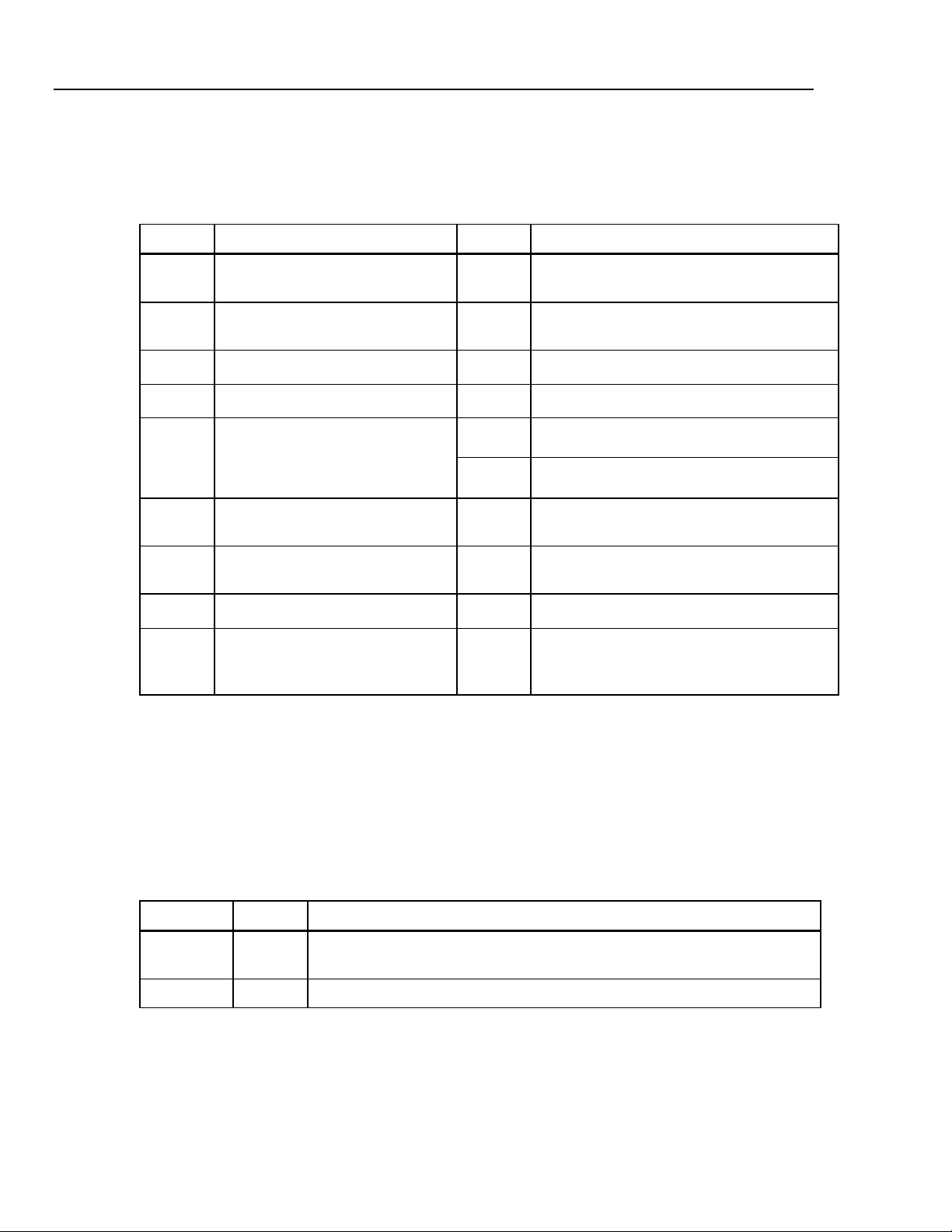
Symbols
Table 1-2 is a list of safety and electrical symbols that appear on the Meter or in this
manual.
Table 1-2. Safety and Electrical Symbols
Symbol Description Symbol Description
W
X
B
F
D
or
C
R
Y
T
h
Risk of danger. Important
information. See manual
Hazardous voltage. Voltage > 30 V
dc or ac peak might be present
AC (Alternating Current)
DC (Direct Current)
AC or DC (Alternating or Direct
Current)
Continuity test or continuity beeper
tone
Potentially hazardous voltage
Double insulated
Static awareness. Static discharge
can damage part(s)
O
J
E
G
I
Y
U
CAT II
<
~
Display ON / OFF
Earth ground
Capacitance
Diode
Fuse
Digital signal
Maintenance or Service
IEC 61010 Overvoltage (installation or
measurement) Category 2.
Recycle
Do not dispose of this product as unsorted
municipal waste. Contact Fluke or a qualified
recycler for disposal
1-6
Instrument Security Procedures
This section describes the Meter’s memory elements and the procedures for clearing
them.
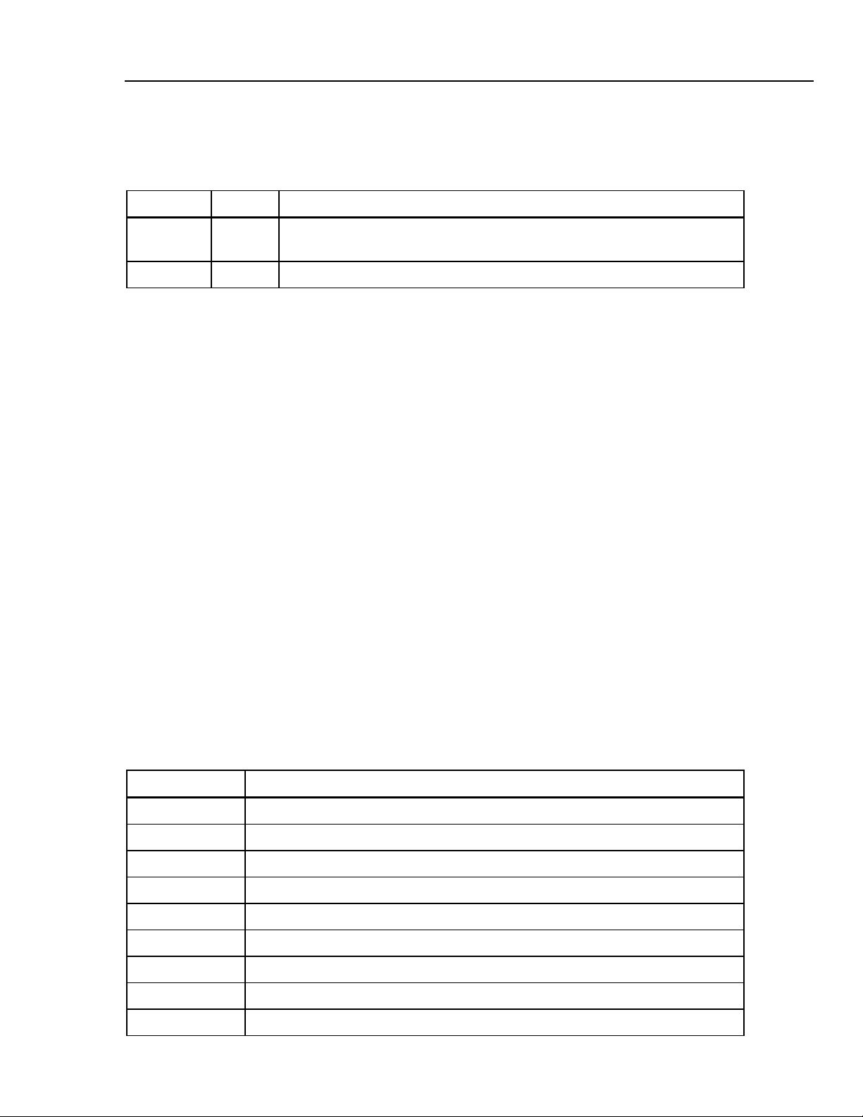
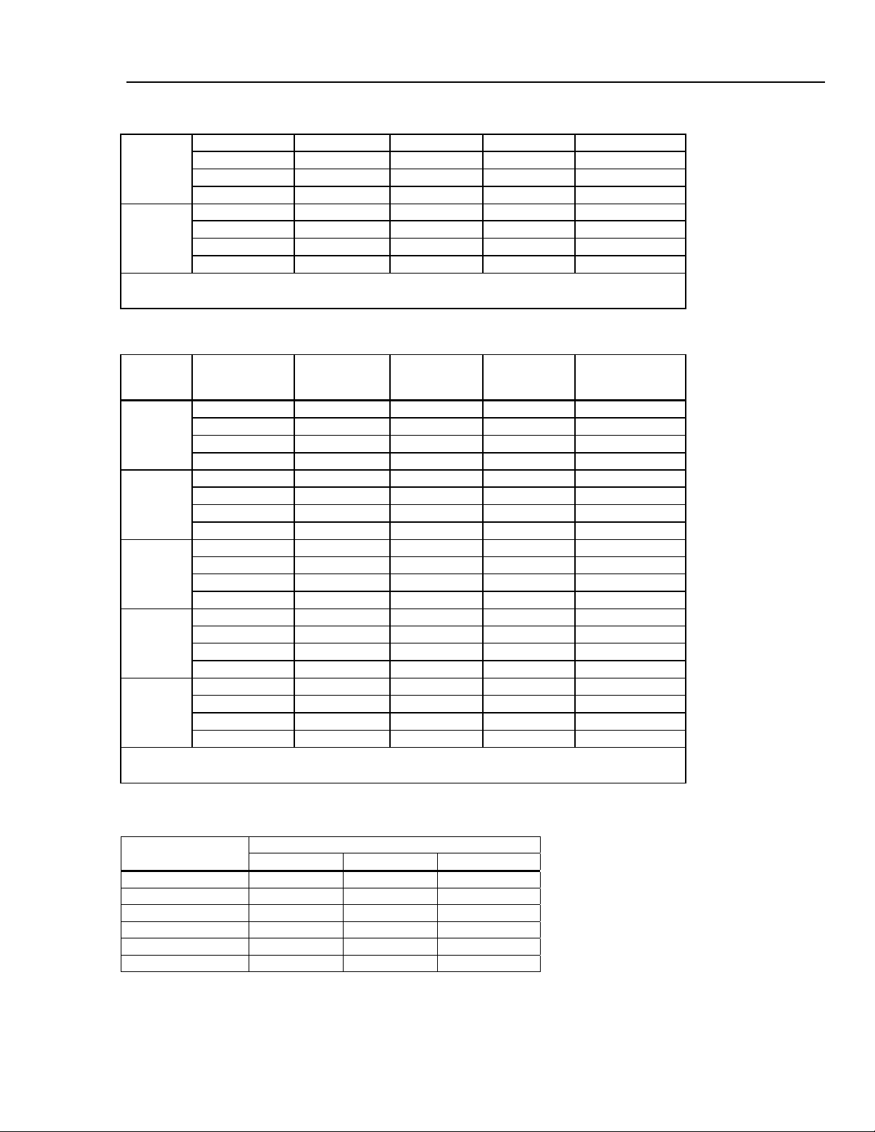
Volatile Memory
Table 1-3 lists the Meter’s volatile memory elements.
Table 1-3. Volatile Memory Space
Type Size Function
SDRAM 128 MB Out-guard measurement data, user strings, temporary configuration information,
and Ethernet Host name.
SRAM 4 MB In-guard Measurement data and configuration information.
To clear both volatile memory elements listed in Table 1-3:
1. Press M.
2. Select the MANAGE MEMORY soft key.
3. Select the ERASE MEMORY soft key.
Page 17
Introduction and Specifications
Accessories 1
Non Volatile Memory
Table 1-4 lists the Meter’s non-volatile memory elements.
Table 1-4. Non-volatile Memory Space
Type Size Function
Flash 128 MB Application program storage, user string, user data, user remote interface
settings.
Flash 4 MB FPGA hardware setup, application program storage, calibration constants.
To clear the 128 MB of non-volatile flash memory listed in Table 1-4:
1. Press M.
2. Select the MANAGE MEMORY soft key.
3. Select the ERASE MEMORY soft key.
This process clears only the user accessible portion of memory.
Note
The 4 MB non-volatile memory element is not usable and cannot be cleared
by the user.
Media Memory (8846A Only)
The 8846A has a front-panel USB port for connecting flash memory modules up to 2
Gigabytes to store Meter configuration and measurement data. To clear a memory
module while connected to the 8846A:
1. Press M.
2. Select the MANAGE MEMORY soft key.
3. Select the ERASE USB MEMORY soft key.
Accessories
Table 1-3 lists the available accessories for the 8845A and 8846A.
Table 1-5. Accessories
Model/Fluke PN Description
TL71 Premium Test Lead Set
6303 Kelvin Probes
6730 Kelvin Lead Set with Alligator Clips
5940 Kelvin clip set
5143 SMD Test Tweezer Leads
6275 Precision Electronic Probe Set
6344 Basic Electronic DMM Test Set
884X-Short 4-Wire Short
884X-Case Black plastic case
1-7
Page 18

8845A/8846A
Users Manual
Table 1-3. Accessories (cont)
Model/Fluke PN Description
TL910 Precision Electronic Probe Set
TL80A Basic Electronic DMM Test Set
TL2X4W-PT 2X4 Wire Ohms Test Lead
TL2X4W-TWZ 2X4 Wire Ohms SMD Test Tweezer
6262-02 Test Probe Tip Adapter, Extended Fine Point
6263-02 Test Probe Tip Adapter, IC Probe Tip
803293 Fuse, 11 A, 1000 V, Fast, 406INX1.5IN, Buik
943121 Fuse, 440 mA, 1000 V, Fast, 406X1.375, Buik
884X-RTD 100 Ohm RTD Temperature Probe
Y8846 Rackmount Kit. Allows meter to be mounted in a standard 19-inch rack.
Y8021 Shielded IEEE 488 one-meter (39.4 inches) cable, with plug and jack at each end.
Y8022 Shielded IEEE 488 two-meter (78.8 inches) cable, with plug and jack at each end.
884X-USB USB to RS-232 Cable Adapter
RS43 Shielded RS-232 Cable (2 Meters)
884X-ETH Ethernet Cable
884X-512M 512 Mbyte memory (8846A only)
884X-1G 1 Gbyte memory (8846A only)
FVF-SC5 FlukeView Forms, Basic Software
FVF-UG FlukeView Forms, Software Upgrade – No Cable
FVF-SC4 Extended FlukeView Forms with USB Cable
2132558 Calibration, traceable with data
1259800 Calibration, traceable without data
1256480 Calibration, Z540 traceable with data
1258910 Calibration, Z540 traceable, without data
1256990 Calibration, accredited
1024830 Agreement, Extended Warranty
2426684 Agreement, Calibration, Traceable, with data
1-8
1028820 Agreement, Calibration, Traceable, without data
1259170 Agreement, Calibration, Z540 Traceable, with data
1258730 Agreement, Calibration, Z540 Traceable, without data
1259340 Agreement, Calibration, Accredited
2441827 Agreement, Calibration, primary standards lab
1540600 Agreement, Calibration, artifact
Page 19

Introduction and Specifications
General Specifications 1
General Specifications
Power
Voltage
100 V Setting ...................................................... 90 V to 110 V
120 V Setting ...................................................... 108 V to 132 V
220 V Setting ...................................................... 198 V to 242 V
240 V Setting ...................................................... 216 V to 264 V
Frequency ............................................................... 47 Hz to 440 Hz. Automatically sensed at power-on.
Power Consumption................................................ 28 VA peak (12 Watt average)
Dimensions
Height...................................................................... 88 mm (3.46 in.)
Width....................................................................... 217 mm (8.56 in.)
Depth ...................................................................... 297 mm (11.7 in.)
Weight..................................................................... 3.6 kg (8.0 Ibs.)
Shipping Weight...................................................... 5.0 kg (11.0 lbs)
Display
Vacuum Fluorescent Display, dot matrix
Environment
Temperature
Operating ............................................................ 0 °C to 55 °C
Storage ............................................................... -40 °C to 70 °C
Warm Up............................................................. 1 hour to full uncertainty specifications
Relative Humidity (non-condensing)
Operating ............................................................ 0 °C to 28 °C <90 %
Storage ............................................................... -40 °C to 70 °C <95 %
Altitude
Operating ............................................................ 2,000 Meters
Storage ............................................................... 12,000 Meters
Vibration and Shock................................................ Complies with Mil-T-28800E Type III, Class 5 (Sine Only)
28 °C to 40 °C <80 %
40 °C to 55 °C <50 %
Safety
Designed to comply with IEC 61010-1:2000-1, UL 61010-1A1, CAN/CSA-C22.2 No. 61010.1, CAT I 1000V/CAT II 600V
EMC
Designed to comply with IEC 61326-1:2000-11 (EMC) when used with shielded communications cables. This Meter has
shown susceptibity to radiated frequencies greater than 1 V/m from 250 to 450 MHz while in the 100 µA range.
Triggering
Samples per Trigger ...........................................1 to 50,000
Trigger Delay ...................................................... 0 S to 3600 S; in 10 µS increments
External Trigger Delay ........................................ <1 mS
External Trigger Jitter ......................................... <500 µS
Trigger Input ....................................................... TTL Levels
Trigger Output..................................................... 5 V maximum. (Open collector)
1-9
Page 20

8845A/8846A
Users Manual
Memory
Math Functions
Zero, dBm, dB, MX+B, Trend-plot, Histogram, Statistics (min/max/average/standard deviation), and Limit Test
Electrical
Input Protection .................................................... 1000 V all ranges
Overrange .............................................................. 20 % on all ranges except 1000 V dc, 1000 V ac (8846A),
Remote Interfaces
Warranty
8845A ................................................................. 10,000 measurements, Internal only
8846A ................................................................. 10,000 measurements, Internal and up to 2 Gigabyte capacity with
USB memory module (available separately. see “Accessories”) through
front-panel USB port
750 V ac (8845A), Diode, and 10 A ranges
RS-232 (RS-232 to USB cable available to connect the Meter to a PC USB port. See accessories)
IEEE 488.2
LAN
One year
Electrical Specifications
Accuracy specifications are valid for 6½ digit mode after at least a 1-hour warm-up with Auto Zero is enabled.
24-hour specifications are relative to calibration standards and assume a controlled electromagnetic environment per
EN 61326-1:2000-11
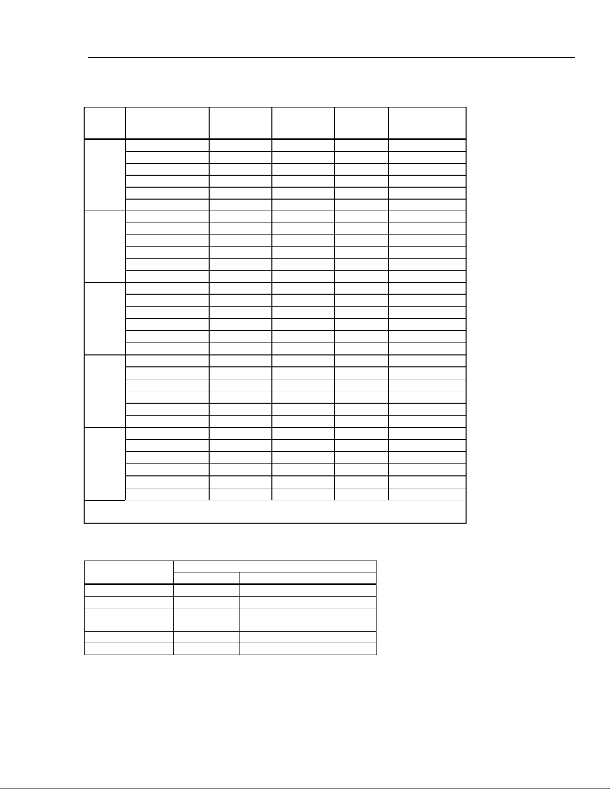
DC Voltage Specifications
Maximum Input...................................................... 1000 V on any range
Common Mode Rejection..................................... 140 dB at 50 or 60 Hz ± 0.1 % (1 kΩ unbalance)
Normal Mode Rejection ........................................ 60 dB for NPLC of 1 or greater with dc filter off and power line
Measurement Method ........................................... Multi-ramp A/D
A/D Linearity.......................................................... 0.0002 % of measurement + 0.0001 % of range
Input Bias Current................................................. <30 pA at 25 °C
Autozero Off Operation ........................................ Following instrument warm-up at calibration temperature ±1 °C and
Settling Considerations........................................ Measurement settling times are affected by source impedance, cable
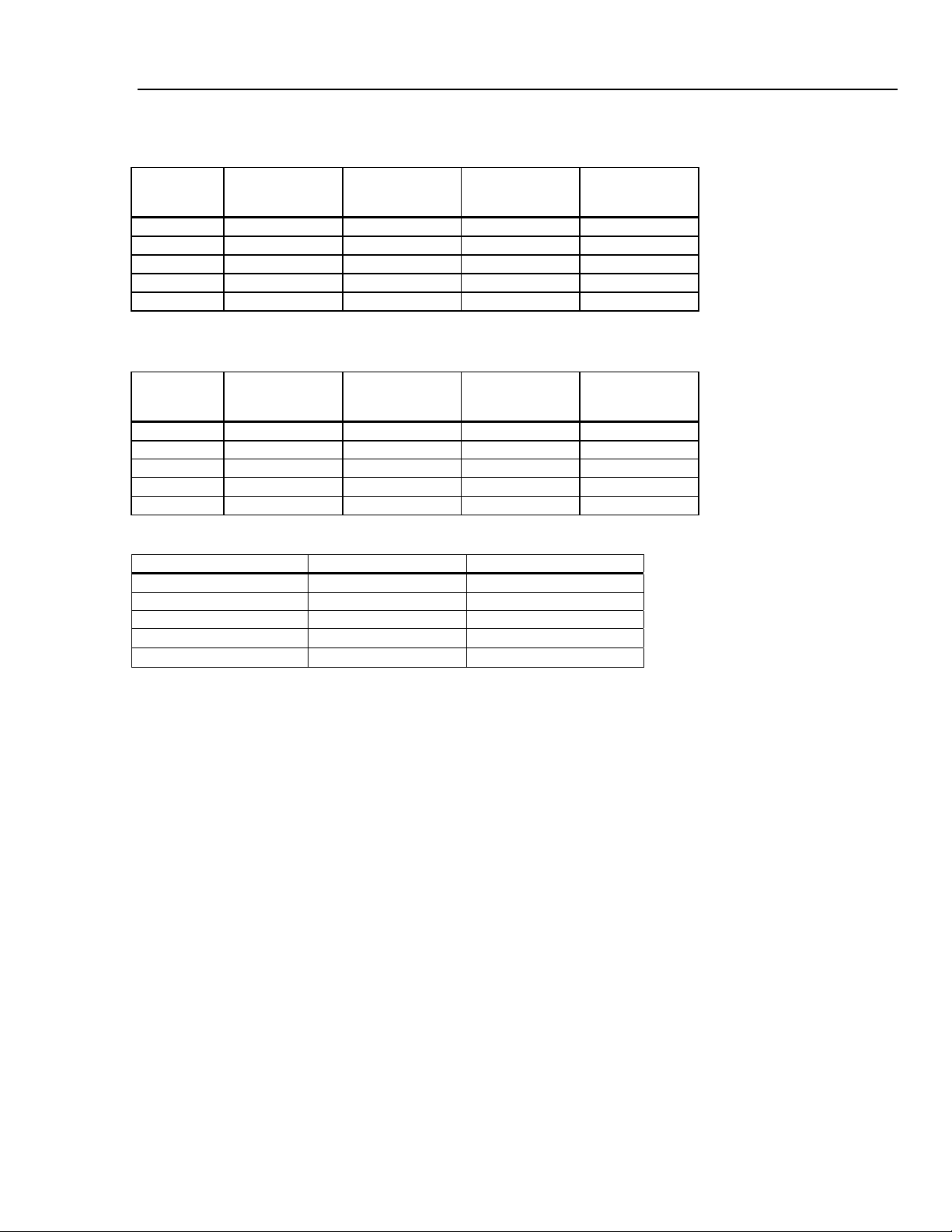
Input Characteristics
Range
100 mV 100.0000 mV 10 µV 1 µV 100 nV
1 V 1.000000 V 100 µV 10 µV 1 µV
10 V 10.00000 V 1 mV 100 µV 10 µV
100 V 100.0000 V 10 mV 1 mV 100 µV
1000 V 1,000.000 V 100 mV 10 mV 1 mV
[1] Inputs beyond ±14 V are clamped through 200 kΩ typical. 10 MΩ is default input impedance.
Full Scale
(6½ Digits)
4½ Digits 5½ Digits 6½ Digits
frequency ±0.1 %
100 dB for NPLC of 1 or greater with dc filter on and power line
frequency ±0.1 %
less than 10 minutes, add error: 0.0002 % range additional error + 5
µV.
dielectric characteristics, and input signal changes.
Resolution
Input Impedance
10 MΩ or >10 GΩ
10 MΩ or >10 GΩ
10 MΩ or >10 GΩ
10 MΩ ±1%
10 MΩ ±1%
[1]
[1]
[1]
1-10
Page 21
Introduction and Specifications
Electrical Specifications 1
8846A Accuracy
Accuracy is given as ± (% measurement + % of range)
Range
100 mV 0.0025 + 0.003 0.0025 + 0.0035 0.0037 + 0.0035 0.0005 + 0.0005
1 V 0.0018 + 0.0006 0.0018 + 0.0007 0.0025 + 0.0007 0.0005 + 0.0001
10 V 0.0013 + 0.0004 0.0018 + 0.0005 0.0024 + 0.0005 0.0005 + 0.0001
100 V 0.0018 + 0.0006 0.0027 + 0.0006 0.0038 + 0.0006 0.0005 + 0.0001
1000 V 0.0018 + 0.0006 0.0031 + 0.001 0.0041 + 0.001 0.0005 + 0.0001
24 Hour
(23 ± 1 °C)
90 Days
(23 ± 5 °C)
1 Year
(23 ± 5 °C)
Temperature
Coefficient/ °C
Outside 18 to 28 °C
8845A Accuracy
Accuracy is given as ± (% measurement + % of range)
Range
100 mV 0.003 + 0.003 0.004 + 0.0035 0.005 + 0.0035 0.0005 + 0.0005
1 V 0.002 + 0.0006 0.003 + 0.0007 0.004 + 0.0007 0.0005 + 0.0001
10 V 0.0015 + 0.0004 0.002 + 0.0005 0.0035 + 0.0005 0.0005 + 0.0001
100 V 0.002 + 0.0006 0.0035 + 0.0006 0.0045 + 0.0006 0.0005 + 0.0001
1000 V 0.002 + 0.0006 0.0035 + 0.0010 0.0045 + 0.0010 0.0005 + 0.0001
24 Hour
(23 ± 1 °C)
90 Days
(23 ± 5 °C)
1 Year
(23 ± 5 °C)
Temperature
Coefficient/ °C
Outside 18 to 28 °C
Additional Errors
Digits NPLC Additional Noise Error
6½ 100 0 % of range
6½ 10 0 % of range
5½ 1 0.001 % of range
5½ .2
4½ 0.02
0.001 % of range + 20 µV
0.01 % of range + 20 µV
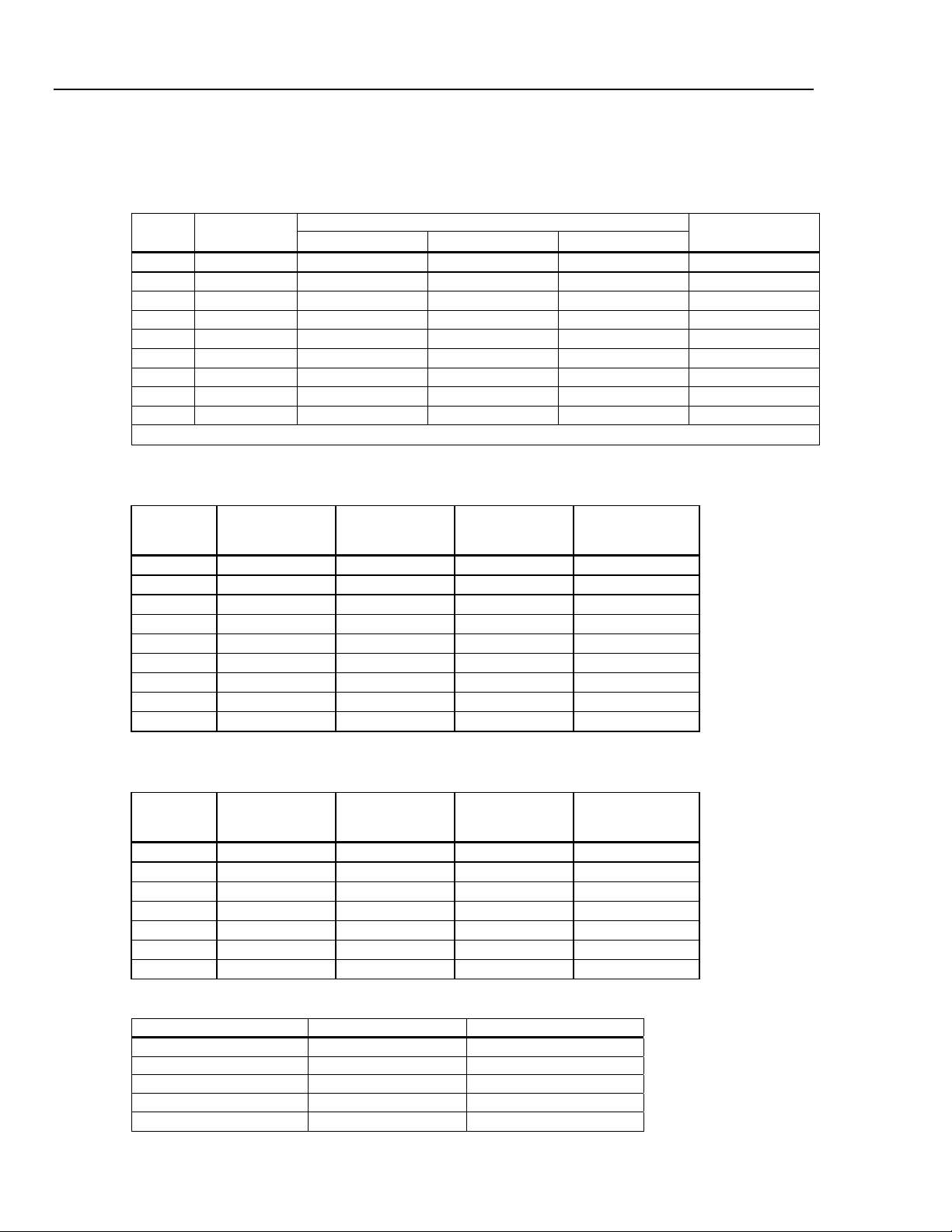
AC Voltage Specifications
AC Voltage specifications are for ac sinewave signals >5 % of range. For inputs from 1 % to 5 % of range and <50 kHz,
add an additional error of 0.1 % of range, and for 50 to 100 kHz, add 0.13 % of range.
Maximum Input...................................................... 750 V rms or 1000 V peak (8845A), 1000 V rms or 1414 V peak
(8846A) or 8 x 10
range.
Measurement Method ........................................... AC-coupled true-rms. Measures the ac component of input with up to
1000 V dc bias on any range.
AC Filter Bandwidth:
Slow .................................................................... 3 Hz – 300 kHz
Medium ............................................................... 20 Hz – 300 kHz
Fast..................................................................... 200 Hz – 300 kHz
Common Mode Rejection..................................... 70 dB at 50 Hz or 60 Hz ±0.1 % (1 kΩ unbalance)
Maximum Crest Factor .........................................5:1 at Full Scale
Additional Crest Factor Errors (<100 Hz) ........... Crest Factor 1-2, 0.05 % of full scale
Crest Factor 2-3, 0.2 % of full scale
Crest Factor 3-4, 0.4 % of full scale
Crest Factor 4-5, 0.5 % of full scale
7
Volts-Hertz product (whichever is less) for any
1-11
Page 22
8845A/8846A
Users Manual
Input Characteristics
Range
100 mV 100.0000 mV 10 µV 1 µV 100 nV
1 V 1.000000 V 100 µV 10 µV 1 µV
10 V 10.00000 V 1 mV 100 µV 10 µV
100 V 100.0000 V 10 mV 1 mV 100 µV
1000 V 1,000.000 V 100 mV 10 mV 1 mV
8846A Accuracy
Accuracy is given as ± (% measurement + % of range)
100 mV
1 V
10 V
100 V
1000 V
Full Scale
(6½ Digits)
Range Frequency
3 – 5 Hz 1.0 + 0.03 1.0 + 0.04 1.0 + 0.04 0.1 + 0.004
5 – 10 Hz 0.35 + 0.03 0.35 + 0.04 0.35 + 0.04 0.035 + 0.004
10 Hz – 20 kHz 0.04 + 0.03 0.05 + 0.04 0.06 + 0.04 0.005 + 0.004
20 – 50 kHz 0.1 + 0.05 0.11 + 0.05 0.12 + 0.05 0.011 + 0.005
50 – 100 kHz 0.55 + 0.08 0.6 + 0.08 0.6 + 0.08 0.06 + 0.008
100 – 300 kHz
[1]
4.0 + 0.50 4.0 + 0.50 4.0 + 0.50 0.20 + 0.02
3 – 5 Hz 1.0 + 0.02 1.0 + 0.03 1.0 + 0.03 0.1 + 0.003
5 – 10 Hz 0.35 + 0.02 0.35 + 0.03 0.35 + 0.03 0.035 + 0.003
10 Hz – 20 kHz 0.04 + 0.02 0.05 + 0.03 0.06 + 0.03 0.005 + 0.003
20 – 50 kHz 0.1 + 0.04 0.11 + 0.05 0.12 + 0.05 0.011 + 0.005
50 – 100 kHz 0.55 + 0.08 0.6 + 0.08 0.6 + 0.08 0.06 + 0.008
100 – 300 kHz
[1]
4.0 + 0.50 4.0 + 0.50 4.0 + 0.50 0.2 + 0.02
3 – 5 Hz 1.0 + 0.02 1.0 + 0.03 1.0 + 0.03 0.1 + 0.003
5 – 10 Hz 0.35 + 0.02 0.35 + 0.03 0.35 + 0.03 0.035 + 0.003
10 Hz – 20 kHz 0.04 + 0.02 0.05 + 0.03 0.06 + 0.03 0.005 + 0.003
20 – 50 kHz 0.1 + 0.04 0.11 + 0.05 0.12 + 0.05 0.011 + 0.005
50 – 100 kHz 0.55 + 0.08 0.6 + 0.08 0.6 + 0.08 0.06 + 0.008
100 –- 300 kHz
[1]
4.0 + 0.50 4.0 + 0.50 4.0 + 0.50 0.2 + 0.02
3 – 5 Hz 1.0 + 0.02 1.0 + 0.03 1.0 + 0.03 0.1 + 0.003
5 – 10 Hz 0.35 + 0.02 0.35 + 0.03 0.35 + 0.03 0.035 + 0.003
10 Hz – 20 kHz 0.04 + 0.02 0.05 + 0.03 0.06 + 0.03 0.005 + 0.003
20 – 50 kHz 0.1 + 0.04 0.11 + 0.05 0.12 + 0.05 0.011 + 0.005
50 – 100 kHz
100 – 300 kHz
[1] Typically 30 % reading error at 1 MHz
[2] 1000 Volt range is limited to 8 X 10
[2]
0.55 + 0.08 0.6 + 0.08 0.6 + 0.08 0.06 + 0.008
[1][2]
4.0 + 0.5 4.0 + 0.50 4.0 + 0.50 0.2 + 0.02
Resolution
4½ Digits 5½ Digits 6½ Digits
24 Hour
(23 ± 1 °C)
7
volt-Hertz
90 Days
(23 ± 5 °C)
1 Year
(23 ± 5 °C)
Temperature
Coefficient/ °C
Outside 18 to 28 °C
Input Impedance
1 MΩ ±2 % shunted
by <100 pf
1-12
Page 23
Introduction and Specifications
Electrical Specifications 1
8845A Accuracy
Accuracy is given as ± (% measurement + % of range)
Range
100 mV
Frequency
(Hz)
3 – 5 Hz 1.0 + 0.03 1.0 + 0.04 1.0 + 0.04 0.10 + 0.004
5 – 10 Hz 0.35 + 0.03 0.35 + 0.04 0.35 + 0.04 0.035 + 0.004
10 Hz – 20 kHz 0.04 + 0.03 0.05 + 0.04 0.06 + 0.04 0.005 + 0.004
20 – 50 kHz 0.1 + 0.05 0.11 + 0.05 0.12 + 0.05 0.011 + 0.005
1 V
50 – 100 kHz 0.55 + 0.08 0.6 + 0.08 0.6 + 0.08 0.06 + 0.008
100 – 300 kHz
3 – 5 Hz 1.0 + 0.02 1.0 + 0.03 1.0 + 0.03 0.1 + 0.003
[1]
4.0 + 0.50 4.0 + 0.50 4.0 + 0.50 0.2 + 0.02
5 – 10 Hz 0.35 + 0.02 0.35 + 0.03 0.35 + 0.03 0.035 + 0.003
10 Hz – 20 kHz 0.04 + 0.02 0.05 + 0.03 0.06 + 0.03 0.005 + 0.003
20 – 50 kHz 0.1 + 0.04 0.11 + 0.05 0.12 + 0.05 0.011 + 0.005
10 V
50 – 100 kHz 0.55 + 0.08 0.6 + 0.08 0.6 + 0.08 0.06 + 0.008
100 – 300 kHz
3 – 5 Hz 1.0 + 0.02 1.0 + 0.03 1.0 + 0.03 0.1 + 0.003
[1]
4.0 + 0.50 4.0 + 0.50 4.0 + 0.50 0.2 + 0.02
5 – 10 Hz 0.35 + 0.02 0.35 + 0.03 0.35 + 0.03 0.035 + 0.003
10 Hz – 20 kHz 0.04 + 0.02 0.05 + 0.03 0.06 + 0.03 0.005 + 0.003
20 – 50 kHz 0.1 + 0.04 0.11 + 0.05 0.12 + 0.05 0.011 + 0.005
50 – 100 kHz 0.55 + 0.08 0.6 + 0.08 0.6 + 0.08 0.06 + 0.008
[1]
4.0 + 0.50 4.0 + 0.50 4.0 + 0.50 0.2 + 0.02
100 V
100 – 300 kHz
3 – 5 Hz 1.0 + 0.02 1.0 + 0.03 1.0 + 0.03 0.1 + 0.003
5 – 10 Hz 0.35 + 0.02 0.35 + 0.03 0.35 + 0.03 0.035 + 0.003
10 Hz – 20 kHz 0.04 + 0.02 0.05 + 0.03 0.06 + 0.03 0.005 + 0.003
20 – 50 kHz 0.1 + 0.04 0.11 + 0.05 0.12 + 0.05 0.011 + 0.005
50 – 100 kHz 0.55 + 0.08 0.6 + 0.08 0.6 + 0.08 0.06 + 0.008
[1]
4.0 + 0.50 4.0 + 0.50 4.0 + 0.50 0.2 + 0.02
750 V
100 – 300 kHz
3 –- 5 Hz 1.0 + 0.02 1.0 + 0.03 1.0 + 0.03 0.1 + 0.003
5 – 10 Hz 0.35 + 0.02 0.35 + 0.03 0.35 + 0.03 0.035 + 0.003
10 Hz – 20 kHz 0.04 + 0.02 0.05 + 0.03 0.06 + 0.03 0.005 + 0.003
20 – 50 kHz 0.1 + 0.04 0.11 + 0.05 0.12 + 0.05 0.011 + 0.005
50 – 100 kHz
100 – 300 kHz
[1] Typically 30 % reading error at 1 MHz
[2] 750 Volt range is limited to 8 X 10
[2]
0.55 + 0.08 0.6 + 0.08 0.6 + 0.08 0.06 + 0.008
[1] [2]
4.0 + 0.5 4.0 + 0.5 4.0 + 0.5 0.2 + 0.02
24 Hour
(23 ± 1 °C)
7
volt-Hertz
90 Days
(23 ± 5 °C)
1 Year
(23 ± 5 °C)
Temperature
Coefficient/ °C
Outside 18 to 28 °C
Additional Low Frequency Errors
Error is stated as % of reading.
Frequency
3HZ (slow) 20HZ (medium) 200HZ (fast)
AC Filter
10 – 20 Hz 0 0.25 –
20 – 40 Hz 0 0.02 –
40 – 100 Hz 0 0.01 0.55
100 – 200 Hz 0 0 0.2
200 Hz – 1 kHz 0 0 0.02
> 1 kHz 0 0 0
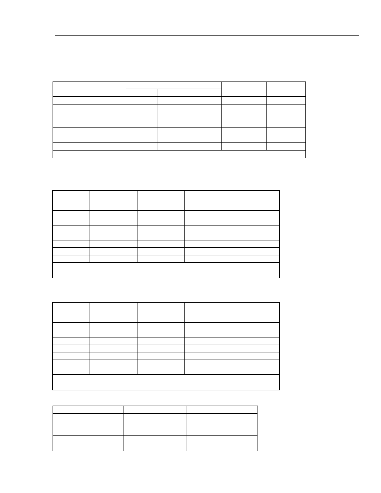
Resistance
Specifications are for 4-wire resistance function, 2 x 4-wire resistance, or 2-wire resistance with zero. If zero is not used,
add 0.2 Ω for 2-wire resistance plus lead resistance, and add 20 mΩ for 2 x 4-wire resistance function.
Measurement Method ........................................... Current source referenced to LO input.
1-13
Page 24
8845A/8846A
Users Manual
Max. Lead Resistance (4-wire ohms) ..................10 % of range per lead for 100 Ω, 1 kΩ ranges. 1 kΩ per lead on all
Input Protection .................................................... 1000 V on all ranges.
other ranges.
Input Characteristics
Range
[1]
10 Ω
100 Ω 100.0000 Ω 10 mΩ 1 mΩ 100 µΩ
1 kΩ 1.000000 kΩ 100 mΩ 10 mΩ 1 mΩ
10 kΩ 10.00000 kΩ 1 Ω 100 mΩ 10 mΩ 100 µA
100 kΩ 100.0000 kΩ 10 Ω 1 Ω 100 mΩ 10 µA
1 MΩ 1.000000 MΩ 100 Ω 10 Ω 1 Ω 10 µA
10 MΩ 10.00000 MΩ 1 kΩ 100 Ω 10 Ω 1 µA
100 MΩ 100.0000 MΩ 10 kΩ 1 kΩ 100 Ω 1 µA || 10 MΩ
1.0 GΩ
[1] 8846A Only
Full Scale
(6½ Digits)
10.00000 Ω 1 mΩ 100 µΩ 10 µΩ
[1]
1.000000 GΩ 100 kΩ 10 kΩ 1 kΩ 1 µA || 10 MΩ
4½ Digits 5½ Digits 6½ Digits
Resolution
Source Current
5 mA
1 mA
1 mA
8846A Accuracy
Accuracy is given as ± (% measurement + % of range)
Range
10 Ω 0.003 + 0.01 0.008 + 0.03 0.01+ 0.03 0.0006 + 0.0005
100 Ω 0.003 + 0.003 0.008 + 0.004 0.01 + 0.004 0.0006 + 0.0005
1 kΩ 0.002 + 0.0005 0.008 + 0.001 0.01 + 0.001 0.0006 + 0.0001
10 kΩ 0.002 + 0.0005 0.008 + 0.001 0.01 + 0.001 0.0006 + 0.0001
100 kΩ 0.002 + 0.0005 0.008 + 0.001 0.01 + 0.001 0.0006 + 0.0001
1 MΩ 0.002 + 0.001 0.008 + 0.001 0.01 + 0.001 0.001 + 0.0002
10 MΩ 0.015 + 0.001 0.02 + 0.001 0.04 + 0.001 0.003 + 0.0004
100 MΩ 0.3 + 0.01 0.8 + 0.01 0.8 + 0.01 0.15 + 0.0002
1 GΩ 1.0 + 0.01 1.5 + 0.01 2.0 + 0.01 0.6 + 0.0002
24 Hour
(23 ± 1 °C)
90 Days
(23 ± 5 °C)
1 Year
(23 ± 5 °C)
Temperature
Coefficient/ °C
Outside 18 to 28 °C
1-14
8845A Accuracy
Accuracy is given as ± (% measurement + % of range)
Range
100 Ω 0.003 + 0.003 0.008 + 0.004 0.01 + 0.004 0.0006 + 0.0005
1 kΩ 0.002 + 0.0005 0.008 + 0.001 0.01 + 0.001 0.0006 + 0.0001
10 kΩ 0.002 + 0.0005 0.008 + 0.001 0.01 + 0.001 0.0006 + 0.0001
100 kΩ 0.002 + 0.0005 0.008 + 0.001 0.01 + 0.001 0.0006 + 0.0001
1 MΩ 0.002 + 0.001 0.008 + 0.001 0.01 + 0.001 0.0010 + 0.0002
10 MΩ 0.015 + 0.001 0.02 + 0.001 0.04 + 0.001 0.0030 + 0.0004
100 MΩ 0.3 + 0.01 0.8 + 0.01 0.8 + 0.01 0.1500 + 0.0002
24 Hour
(23 ± 1 °C)
90 Days
(23 ± 5 °C)
1 Year
(23 ± 5 °C)
Temperature
Coefficient/ °C
Outside 18 to 28 °C
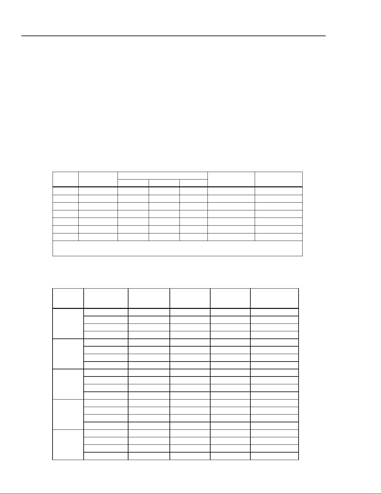
Additional Ohms Errors
Digits NPLC Additional Noise Error
6½ 100 0 % of range
6½ 10 0 % of range
5½ 1 0.001 % of range
5½ 0.2
4½ 0.02
0.001 % of range ± 20 mΩ
0.01 % of range ± 20 mΩ
Page 25
Introduction and Specifications
Electrical Specifications 1
DC Current
Input Protection .................................................... Tool-accessible 11 A/1000 V and 440 mA/1000 V fuses.
Input Characteristics
Range
100 µA 100.0000 µA 10 nA 1 nA 100 pA
1 mA 1.000000 mA 100 nA 10 nA 1 nA
10 mA 10.00000 mA
100 mA 100.0000 mA 10 µA
1 A 1.000000 A 100 µA 10 µA
[1]
3 A
3.00000A 1 mA 100 µA 10 µA
10 A 10.00000 A 1 mA 100 µA 10 µA
[1] Part of 10 A range.
Full Scale
(6½ Digits)
4½ Digits 5½ Digits 6½ Digits
1 µA
Resolution
100 nA 10 nA
1 µA
100 nA
1 µA 0.01 Ω
Shunt Resistance
(Ohms)
100Ω
100Ω
1 Ω
1 Ω
0.01 Ω
0.01 Ω
Burden Voltage
<0.015
<0.15
<0.025 V
<0.25 V
<0.05 V
<0.15 V
<0.5 V
Accuracy (8846A)
Accuracy is given as ± (% measurement + % of range)
Range
100 µA 0.01 + 0.02 0.04 + 0.025 0.05 + 0.025 0.002 + 0.003
1 mA 0.007 + 0.005 0.030 + 0.005 0.05 + 0.005 0.002 + 0.0005
10 mA 0.007 + 0.02 0.03 + 0.02 0.05 + 0.02 0.002 + 0.002
100 mA 0.01 + 0.004 0.03 + 0.005 0.05 + 0.005 0.002 + 0.0005
[2]
1 A
0.03 + 0.02 0.04 + 0.02 0.05 + 0.02 0.005 + 0.001
[1][2]
3 A
0.05 + 0.02 0.08 + 0.02 0.1 + 0.02 0.005 + 0.002
[2]
10 A
0.1 + 0.008 0.12 + 0.008 0.15 + 0.008 0.005 + 0.0008
[1] Part of 10 A range
[2] Available at front panel connectors only
24 Hour
(23 ± 1 °C)
90 Days
(23 ± 5 °C)
1 Year
(23 ± 5 °C)
Temperature
Coefficient/ °C
Outside 18 to 28 °C
Accuracy (8845A)
Accuracy is given as ± (% measurement + % of range)
Range
100 µA 0.01 + 0.02 0.04 + 0.025 0.05 + 0.025 0.002 + 0.003
1 mA 0.007 + 0.005 0.030 + 0.005 0.05 + 0.005 0.002 + 0.0005
10 mA 0.007 + 0.02 0.03 + 0.02 0.05 + 0.02 0.002 + 0.002
100 mA 0.01 + 0.004 0.03 + 0.005 0.05 + 0.005 0.002 + 0.0005
[2]
1 A
0.03 + 0.04 0.08 + 0.02 0.05 + 0.02 0.005 + 0.001
[1][2]
3 A
0.05 + 0.08 0.12 + 0.02 0.1 + 0.02 0.005 + 0.002
[2]
10 A
0.1 + 0.008 0.12 + 0.008 0.15 + 0.02 0.005 + 0.0008
[1] Part of 10 A range
[2] Available at front panel connectors only
24 Hour
(23 ± 1 °C)
90 Days
(23 ± 5 °C)
1 Year
(23 ± 5 °C)
Temperature
Coefficient/ °C
Outside 18 to 28 °C
Additional Current Errors
Digits NPLC Additional Noise Error
6½ 100 0 % of range
6½ 10 0 % of range
5½ 1 0.001 % of range
5½ 0.2
4½ 0.02
1-15
0.001 % of range ± 4 µA
0.01 % of range ± 4 µA
Page 26
8845A/8846A
Users Manual
AC Current
The following ac current specifications are for sinusoidal signals with amplitudes greater than 5 % of range. For inputs
from 1% to 5 % of range, add an additional error of 0.1 % of range.
Input Protection .................................................... Tool accessible 11 A/1000 V and 440 mA/1000 V fuses.
Measurement Method ........................................... ac-coupled true-rms, dc-coupled to the fuse and shunt (no blocking
AC Filter Bandwidth
Maximum Crest Factor .........................................5:1 at full scale
Additional Crest Factor Errors (<100 Hz) ........... Crest Factor 1-2, 0.05 % of full scale
Input Characteristics
100 µA
1 mA
10 mA 10.00000 mA
100 mA 100.0000 mA 10 µA
1 A 1.000000 A 100 µA 10 µA
3 A[2] 3.00000 A 1 mA 100 µA
10 A 10.00000 A 1 mA 100 µA 10 µA
capacitor)
Slow .................................................................... 3 Hz to 10 kHz
Medium ............................................................... 20 Hz to 10 kHz
Fast..................................................................... 200 Hz to 10 kHz
Crest Factor 2-3, 0.2 % of full scale
Crest Factor 3-4, 0.4 % of full scale
Crest Factor 4-5, 0.5 % of full scale
Range
[1] 8846A Only
[2] Part of 10 A range
Full Scale
(6½ Digits)
[1]
100.0000 µA
[1]
1.000000 mA 100 nA 10 nA 1 nA
4½ Digits 5½ Digits 6½ Digits
10 nA 1 nA 100 pA
1 µA
Resolution
100 nA 10 nA
1 µA
100 nA
1 µA 0.01 Ω
10 µA 0.01 Ω
Shunt Resistance
(Ohms)
100Ω
100Ω
1 Ω
1 Ω
0.01 Ω
Burden Voltage
<0.015 V
<0.15 V
<0.025 V
<0.25 V
<0.05 V
<0.05 V
<0.5 V
8846A Accuracy
Accuracy is given as ± (% measurement + % of range)
Range
100 µA
1 mA
10 mA
100 mA
[2]
1 A
Frequency
(Hz)
3 – 5 Hz 1.0 + 0.04 1.0 + 0.04 1.0 + 0.04 0.1 + 0.006
5 – 10 Hz 0.3 + 0.04 0.3 + 0.04 0.3 + 0.04 0.035 + 0.006
10 Hz – 5 kHz 0.1 + 0.04 0.1 + 0.04 0.1 + 0.04 0.015 + 0.006
5 – 10 kHz 0.2 + 0.25 0.2 + 0.25 0.2 + 0.25 0.03 + 0.006
3 – 5 Hz 1.0 + 0.04 1.0 + 0.04 1.0 + 0.04 0.1 + 0.006
5 – 10 Hz 0.3 + 0.04 0.3 + 0.04 0.3 + 0.04 0.035 + 0.006
10 Hz – 5 kHz 0.1 + 0.04 0.1 + 0.04 0.1 + 0.04 0.015 + 0.006
5 – 10 kHz 0.2 + 0.25 0.2 + 0.25 0.2 + 0.25 0.03 + 0.006
3 – 5 Hz 1.0 + 0.04 1.0 + 0.04 1.0 + 0.04 0.1 + 0.006
5 – 10 Hz 0.3 + 0.04 0.3 + 0.04 0.3 + 0.04 0.035 + 0.006
10 Hz – 5 kHz 0.1 + 0.04 0.1 + 0.04 0.1+ 0.04 0.015 + 0.006
5 – 10 kHz 0.2 + 0.25 0.2 + 0.25 0.2 + 0.25 0.03 + 0.006
3 – 5 Hz 1.0 + 0.04 1.0 + 0.04 1.0 + 0.04 0.1 + 0.006
5 – 10 Hz 0.3 + 0.04 0.3 + 0.04 0.3 + 0.04 0.035 + 0.006
10 Hz – 5 kHz 0.1 + 0.04 0.1 + 0.04 0.1 + 0.04 0.015 + 0.006
5 – 10 kHz 0.2 + 0.25 0.2 + 0.25 0.2 + 0.25 0.03 + 0.006
3 – 5 Hz 1.0 + 0.04 1.0 + 0.04 1.0 + 0.04 0.1 + 0.006
5 – 10 Hz 0.3 + 0.04 0.3 + 0.04 0.3 + 0.04 0.035 + 0.006
10 Hz – 5 kHz 0.1 + 0.04 0.1 + 0.04 0.1 + 0.04 0.015 + 0.006
5 – 10 kHz 0.35 + 0.7 0.35 + 0.7 0.35 + 0.7 0.03 + 0.006
24 Hour
(23 ± 1 °C)
90 Days
(23 ± 5 °C)
1 Year
(23 ± 5 °C)
Temperature
Coefficient/ °C
Outside 18 to 28 °C
1-16
Page 27
Introduction and Specifications
Electrical Specifications 1
8846A Accuracy (cont)
[1][2]
3 A
[2]
10 A
[1] Part of 10 A range
[2] Available only on front panel connectors
3 – 5 Hz 1.1 + 0.06 1.1 + 0.06 1.1 + 0.06 0.1 + 0.006
5 – 10 Hz 0.35 + 0.06 0.35 + 0.06 0.35 + 0.06 0.035 + 0.006
10 Hz – 5 kHz 0.5 + 0.7 0.15 + 0.06 0.15 + 0.06 0.015 + 0.006
5 – 10 kHz 0.35 + 0.7 0.35 + 0.7 0.35 + 0.7 0.03 + 0.006
3 – 5 Hz 2.0 + 0.06 2.0 + 0.06 2.0 + 0.06 0.2 + 0.006
5 – 10 Hz 1.1 + 0.06 1.1 + 0.06 1.1 + 0.06 0.1 + 0.006
10 Hz – 5 kHz 0.15 + 0.06 0.15 + 0.06 0.15 + 0.06 0.015 + 0.006
5 – 10 kHz 0.35 + 0.7 0.35 + 0.7 0.35 + 0.7 0.03 + 0.006
8845A Accuracy
Accuracy is given as ± (% measurement + % of range)
Range
10 mA
100 mA
[2]
1 A
[1][2]
3 A
[2]
10 A
[1] Part of the 10 A range
[2] Available only at front panel connectors
Frequency
(Hz)
3 – 5 Hz 1.0 + 0.04 1.0 + 0.04 1.0 + 0.04 0.1 + 0.006
5 – 10 Hz 0.3 + 0.04 0.3 + 0.04 0.3 + 0.04 0.035 + 0.006
10 Hz – 5 kHz 0.1 + 0.04 0.1 + 0.04 0.1+ 0.04 0.015 + 0.006
5 – 10 kHz 0.2 + 0.25 0.2 + 0.25 0.2 + 0.25 0.03 + 0.006
3 – 5 Hz 1.0 + 0.04 1.0 + 0.04 1.0 + 0.04 0.1 + 0.006
5 – 10 Hz 0.3 + 0.04 0.3 + 0.04 0.3 + 0.04 0.035 + 0.006
10 Hz – 5 kHz 0.1 + 0.04 0.1 + 0.04 0.1 + 0.04 0.015 + 0.006
5 – 10 kHz 0.2 + 0.25 0.2 + 0.25 0.2 + 0.25 0.03 + 0.006
3 – 5 Hz 1.0 + 0.04 1.0 + 0.04 1.0 + 0.04 0.1 + 0.006
5 – 10 Hz 0.3 + 0.04 0.3 + 0.04 0.3 + 0.04 0.035 + 0.006
10 Hz – 5 kHz 0.1 + 0.04 0.1 + 0.04 0.1 + 0.04 0.015 + 0.006
5 – 10 kHz 0.35 + 0.7 0.35 + 0.7 0.35 + 0.7 0.03 + 0.006
3 – 5 Hz 1.1 + 0.06 1.1 + 0.06 1.1 + 0.06 0.1 + 0.006
5 – 10 Hz 0.35 + 0.06 0.35 + 0.06 0.35 + 0.06 0.035 + 0.006
10 Hz – 5 kHz 0.15 + 0.06 0.15 + 0.06 0.15 + 0.06 0.015 + 0.006
5 – 10 kHz 0.35 + 0.7 0.35 + 0.7 0.35 + 0.7 0.03 + 0.006
3 – 5 Hz 1.1 + 0.04 1.1 + 0.04 1.1 + 0.04 0.2 + 0.006
5 – 10 Hz 0.35 + 0.04 0.35 + 0.04 0.35 + 0.04 0.1 + 0.006
10 Hz – 5 kHz 0.15 + 0.04 0.15 + 0.04 0.15 + 0.04 0.015 + 0.006
5 – 10 kHz 0.35 + 0.7 0.35 + 0.7 0.35 + 0.7 0.03 + 0.006
24 Hour
(23 ± 1 °C)
90 Days
(23 ± 5 °C)
1 Year
(23 ± 5 °C)
Temperature
Coefficient/ °C
Outside 18 to 28 °C
Additional Low Frequency Errors
Error is stated as % of reading.
Frequency
10 – 20 Hz 0 0.25 –
20 – 40 Hz 0 0.02 –
40 – 100 Hz 0 0.01 0.55
100 – 200 Hz 0 0 0.2
200 Hz – 1 kHz 0 0 0.02
> 1 kHz 0 0 0
3HZ (slow) 20HZ (medium) 200HZ (fast)
AC Filter
1-17
Page 28
8845A/8846A
Users Manual
Frequency
Gate Times............................................................. Programmable to 1 s, 100 ms, and 10 ms.
Measurement Method ........................................... Flexible counting technique. AC-coupled input using the ac voltage
Settling Considerations........................................ When measuring frequency or period after a dc offset voltage change,
Measurement Considerations.............................. To minimize measurement errors, shield inputs from external noise
8846A Accuracy
Accuracy is given as ± % measurement
100 mV to
1000 V
measurement function.
errors may occur. For the most accurate measurement, wait up to 1
second for the input blocking capacitor to settle.
when measuring low-voltage, low-frequency signals.
Range Frequency
3 – 5 Hz 0.1 0.1 0.1 0.005
[1][2]
5 – 10 Hz 0.05 0.05 0.05 0.005
10 – 40 Hz 0.03 0.03 0.03 0.001
40 Hz – 300 kHz 0.006 0.01 0.01 0.001
300 kHz – 1 MHz 0.006 0.01 0.01 0.001
[1] Input >100 mV. For 10 – 100 mV, multiply percent measurement error by 10.
[2] Limited to 8 X 10
7
volt-Hertz
24 Hour
(23 ± 1 °C)
90 Days
(23 ± 5 °C)
1 Year
(23 ± 5 °C)
Temperature
Coefficient/ °C
Outside 18 to 28 °C
8845A Accuracy
Accuracy is given as ± % measurement
Range Frequency
100 mV to
750 V
[1] Input >100 mV. For 10 – 100 mV, multiply percent measurement error by 10.
[2] Limited to 8 X 10
3 – 5 Hz 0.1 0.1 0.1 0.005
[1][2]
5 – 10 Hz 0.05 0.05 0.05 0.005
10 – 40 Hz 0.03 0.03 0.03 0.001
40 Hz – 300 kHz 0.006 0.01 0.01 0.001
7
volt-Hertz
24 Hour
(23 ± 1 °C)
90 Days
(23 ± 5 °C)
1 Year
(23 ± 5 °C)
Temperature
Compensation/ °C
Outside 18 to 28 °C
Gate Time vs. Resolution
Gate Time Resolution
0.01 5½
0.1 6½
1.0 6½
Additional Low Frequency Errors
Error stated as percent of measurement for inputs >100 mV. For 10 – 100 mV, multiply percent by 10.
Frequency
3 – 5 Hz 0 0.12 0.12
5 – 10 Hz 0 0.17 0.17
10 – 40 Hz 0 0.2 0.2
40 – 100 Hz 0 0.06 0.21
100 – 300 Hz 0 0.03 0.21
300 Hz – 1 kHz 0 0.01 0.07
> 1 kHz 0 0 0.02
6½ 5½ 4½
Resolution
1-18
Page 29

Introduction and Specifications
Electrical Specifications 1
Capacitance (8846A Only)
Accuracy is stated as ±(% of measurement + % of range)
Range Resolution
1 nF 1 pF
10 nF 10 pF
100 nF 100 pF
1 µF 1 nF
10 µF 10 nF
100 µF 100 nF
1 mF 1 µF
10 mF 10 µF
100 mF 100 µF
[1] Stated accuracy is attained when Zero function is used.
1 Year Accuracy
(23 ± 5 °C)
2% ± 2.5 %
1% ± 0.5 %
1% ± 0.5 %
1% ± 0.5 %
1% ± 0.5 %
1% ± 0.5 %
1% ± 0.5 %
1% ± 0.5 %
4% ± 0.2 %
[1]
Temperature Coefficient/ °C
Outside 18 to 28 °C
0.05 + 0.05
0.05 + 0.01
0.01 + 0.01
0.01 + 0.01
0.01 + 0.01
0.01 + 0.01
0.01 + 0.01
0.01 + 0.01
0.05 + 0.05
Temperature (8846A only)
Test Current........................................................... 1 mA
Accuracy is stated as ± °C and is based on a Platinum RT100 (DIN 43760) RTD with less than 10 ohms lead resistance.
Specifications do not include probe accuracy, which must be added.
Accuracy
Range Resolution
-200 °C 0.001 °C
-100 °C 0.001 °C 0.05 0.08 0.002
0 °C 0.001 °C 0.04 0.06 0.002
100 °C 0.001 °C 0.05 0.08 0.002
300 °C 0.001 °C 0.1 0.12 0.002
600 °C 0.001 °C 0.12 0.14 0.002
90 Days
(23 ± 5 °C)
0.06
1 Year
(23 ± 5 °C)
0.09 0.0025
Temperature
Coefficient/ °C
Outside 18 to 28 °C
Additional Temperature Errors
NPLC Additional Noise Error
100
10
1
0.2
0.02
0 °C
0 °C
0.03 °C
0.1 °C
0.4 °C
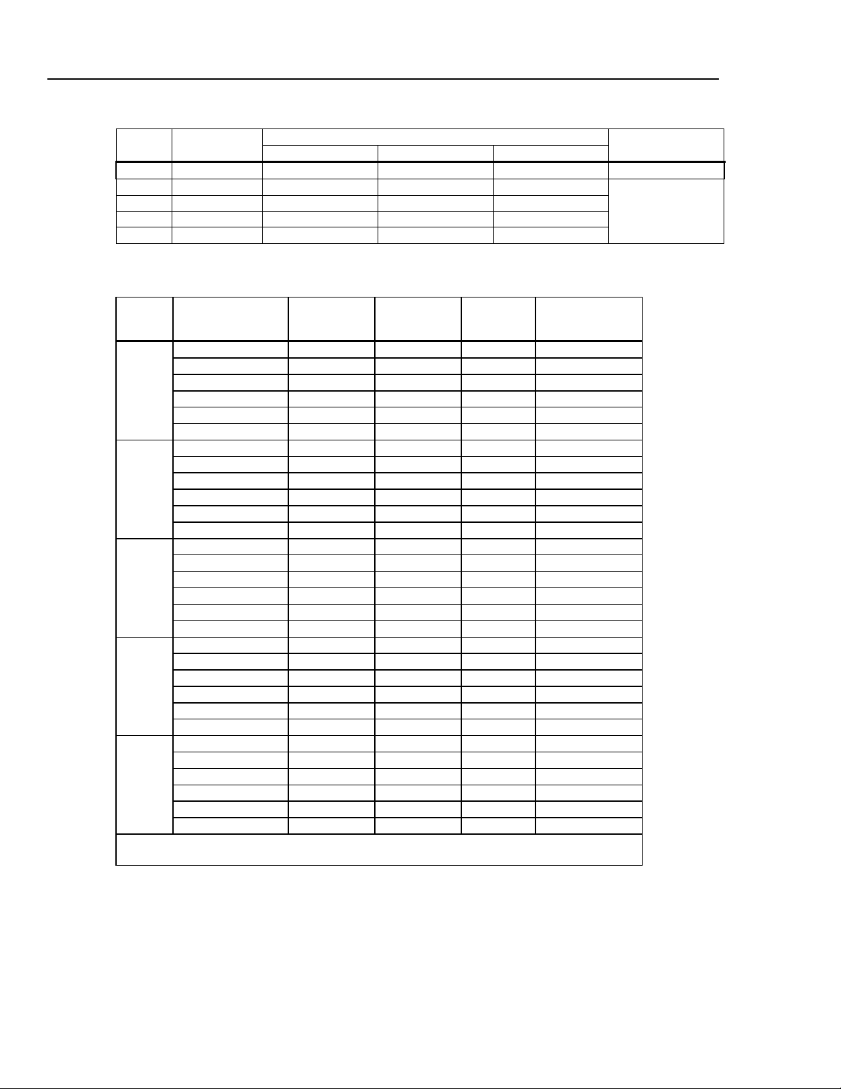
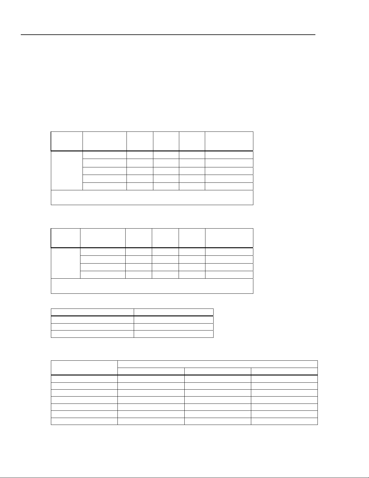
Continuity
Continuity Threshold............................................ Selectable between 1 Ω and 1000 Ω
Test Current........................................................... 1 mA
Response Time ..................................................... 300 samples/sec with audible tone
Accuracy is given as ± (% measurements + % of range)
Range
1000.0 Ω 0.002 + 0.01 0.008 + 0.02 0.01 + 0.02
24 Hour
(23 ± 1 °C)
90 Days
(23 ± 5 °C)
1 Year
(23 ± 5 °C)
Outside 18 to 28 °C
0.001 + 0.002
Temperature
Coefficient/ °C
1-19
Page 30

8845A/8846A
Users Manual
Diode Test
Test Current........................................................... 100 µA or 1 mA
Response Time ..................................................... 300 samples/sec with audible tone.
Accuracy is given as ± (% measurements + % of range)
5.0000 V 0.002 + 0.002 0.008 + 0.002 0.01 + 0.002 0.001 + 0.002
10.0000 V 0.002 + 0.001 0.008 + 0.002 0.01 + 0.002 0.001 + 0.002
Measurement Rates
DC Volts, DC Current, and
Resistance
AC Voltage and AC Current
Frequency and Period
Range
Function Digits Setting
[1] Typical measurement rates with autozero off.
[2] Maximum measurement rates for 0.01 % of ac step. When dc input varies, additional settling delay is required.
[3] For remote operation or external trigger using default settling delay
[4] Settling delay = 0
24 Hour
(23 ± 1 °C)
[2]
90 Days
(23 ± 5 °C)
6½ 100 NPLC 1.67 (2) s 0.6 (0.5) 0.6 (0.5)
6½ 10 NPLC 167 (200) ms 6 (5) 6 (5)
5½ 10 NPLC 16.7 (20) ms 60 (50) 60 (50)
5½ 0.2 NPLC 3 ms 300 300
6½ 3 Hz 0.14 0.14
6½ 20 Hz 1 1
6½ 200 Hz
6½ 200 Hz
6½ 1 s 1 1
5½ 100 ms 9.8 9.8
4½ 10 ms 80 80
[3]
[4]
1 Year
(23 ± 5 °C)
Integration Time
60 Hz (50 Hz)
1.6 1.6
6 6
Temperature
Coefficient/ °C
Outside 18 to 28 °C
Measurements/Second
8845A 8846A
[1]
1-20
Page 31

Chapter 2
Preparing the Meter for Operation
Title Page
Introduction........................................................................................................ 2-3
Unpacking and Inspecting the Meter ................................................................. 2-3
Contacting Fluke................................................................................................ 2-3
Storing and Shipping the Meter ......................................................................... 2-3
Power Considerations ........................................................................................ 2-3
Selecting the Line Voltage ............................................................................ 2-4
Replacing the Fuses....................................................................................... 2-4
Line-Power Fuse ....................................................................................... 2-4
Current-Input Fuses................................................................................... 2-5
Connecting to Line Power ................................................................................. 2-7
Turning Power-On ............................................................................................. 2-8
Adjusting the Bail .............................................................................................. 2-8
Installing the Meter in an Equipment Rack ....................................................... 2-8
Cleaning the Meter............................................................................................. 2-9
2-1
Page 32

8845A/8846A
Users Manual
2-2
Page 33

Preparing the Meter for Operation
Introduction 2
Introduction
This chapter explains how to prepare the Meter for operation by selecting the proper line
voltage, connecting an appropriate line power cord, and turning on the Meter. Also
included is information on the proper storage and cleaning of the Meter.
Unpacking and Inspecting the Meter
Every care is taken in the choice of packing material to ensure that your equipment will
reach you in perfect condition. If the equipment has been subject to excessive handling in
transit, there may be visible external damage to the shipping carton. In the event of
damage, the shipping container and cushioning material should be kept for the carrier’s
inspection.
Carefully unpack the Meter from its shipping container and inspect the contents for
damaged or missing items. If the Meter appears damaged or something is missing,
contact both the carrier and Fluke immediately. Save the container and the packing
material in case you have to return the Meter.
Contacting Fluke
To order accessories, receive operating assistance, or get the location of the nearest Fluke
distributor or Service Center, call:
USA: 1-888-44-FLUKE (1-888-443-5853)
Canada: 1-800-36-FLUKE (1-800-363-5853)
Europe: +31 402-675-200
Japan: +81-3-3434-0181
Singapore: +65-738-5655
Anywhere in the world: +1-425-446-5500
Service in USA: 1-888-99-FLUKE (1-888-993-5853)
Or, visit Fluke's Web site at www.fluke.com.
To register this product, visit register.fluke.com
Storing and Shipping the Meter
The Meter should be stored under cover. The shipping container provides the most
suitable receptacle for storage, as it provides the necessary shock isolation for normal
handling operations.
Place the Meter inside a sealed bag. Place the bag into the cushioning material inside the
shipping container, and store in a location that complies with the storage environment
specification described in Chapter 1.
If the Meter is shipped, use the original shipping container if possible. It provides shock
isolation for normal handling operations. If the original shipping container is not
available, a box that is 17.5″ x 15.5″ x 8.0″, with cushioning material that fills the space
between the Meter and the sides of the box, should provide similar shock isolation.
.
Power Considerations
The Meter operates on power distribution standards found throughout the world, and
must be set up to operate on the line voltage that will power it. The Meter is packed ready
for use with a line voltage determined at the time of ordering. If the selected line voltage
2-3
Page 34

8845A/8846A
Users Manual
Selecting the Line Voltage
does not match the power the Meter will be plugged into, then the Meter’s line voltage
setting must be changed and the line fuse possibly replaced.
The Meter will operate on any one of four different input line voltages. The set line
voltage is visible through the window in the line fuse holder, found on the Meter’s rear
panel.
To change the line voltage:
1. Remove the power cord from the Meter.
2. Insert a small screwdriver blade in the narrow recess to the left of the fuse holder and
pry to the right until the holder pops out, as shown in Figure 2-1.
3. Remove the voltage selector block from the fuse holder.
4. Rotate the selector block until the preferred voltage rating faces outward.
5. Replace the selector block back into the fuse holder.
Changing the line voltage setting may require a different line-power fuse for proper
operation. Check Table 2-1 for the appropriate fuse for the selected line voltage.
With the voltage set and appropriate fuse installed, replace the fuse holder back into the
Meter and reconnect the power cord.
Replacing the Fuses
The Meter employs fuses to protect both the line-power and current measurement inputs.
Line-Power Fuse
The Meter has a line-power fuse in series with the power supply. Table 2-1 indicates the
proper fuse for each of the four line voltage selections. This fuse is located on the rearpanel.
To replace this fuse:
1. Unplug the power cord from the Meter.
2. Remove the fuse holder by inserting a small screwdriver blade in the narrow recess to
the left of the fuse holder and pry to the right until the holder pops out as shown in
Figure 2-1. The Meter is shipped with a replacement fuse of the same rating as the
fuse installed in the fuse block.
3. Remove the fuse and replace with one rated appropriately for the selected line-power
voltage. See Table 2-1.
4. Replace the selector block back into the fuse holder.
To avoid electric shock or fire, do not use makeshift fuses or
short-circuit the fuse holder. Use only Fluke fuses
XW Warning
2-4
Page 35

Preparing the Meter for Operation
Table 2-1. Line Voltage to Fuse Rating
Line Voltage Selection Fuse Rating Fluke Part No.
100 0.25 A, 250 V (slow blow) 166306
120 0.25 A, 250 V (slow blow) 166306
220 0.125 A, 250 V (slow blow) 166488
240 0.125 A, 250 V (slow blow) 166488
Power Considerations 2
Current-Input Fuses
The 100 mA and 10 A inputs are protected by user-replaceable fuses.
• The 100 mA input is protected by a fuse (F2) rated at 440 mA, 1000 V (fast
blow), 10,000 A minimum breaking capacity (Fluke Part No. 943121).
• The 10 A input is protected by a fuse (F1) rated at 11 A, 1000 V (fast blow),
10,000 A minimum breaking capacity (Fluke Part No. 803293).
For protection against fire or arc flash, replace a blown fuse
only with one from Fluke.
To test for a blown Current Input Fuse:
1. With the Meter powered up, plug a test lead into the VΩGER connector.
2. Press N.
Figure 2-1. Replacing the Line Fuse
W Warning
120
caw0201f.eps
3. Insert the other end of the test lead into the 100 mA input connector.
If the fuse is good, the Meter will read less than 200 Ω. If the fuse is blown, the
Meter will read overload.
4. Remove the probe from the 100 mA connector and insert into the 10 A
connector.
2-5
Page 36

8845A/8846A
Users Manual
If the fuse is good, the Meter will read less than 1 Ω. If the fuse is blown, the
Meter will read overload.
To replace the Current Input fuses,
1. Turn the Meter off, unplug the power cord from the Meter, and remove all test
leads.
2. Turn the Meter on its back.
3. Unscrew the retaining screw on the fuse access door as depicted in Figure 2-2.
4. Remove the protective cover from the fuse holders by slightly depressing the
back edge of the cover to unlatch it from the printed circuit board. Pull up on the
back edge of the cover and remove it from the fuse compartment.
5. Remove the defective fuse, and replace with one having the appropriate rating.
6. Replace the protective cover by pushing it over the fuses while aligning the
catches with the holes in the printed circuit board. Press the cover down until the
catches engage the printed circuit board.
7. Replace the fuse door and secure it by tightening the retaining screw.
2-6
Fuses
Figure 2-2. Replacing the Current Input Fuses
F1
F2
Bottom front
left corner
caw020.eps
Page 37

Preparing the Meter for Operation
Connecting to Line Power 2
Connecting to Line Power
XWWarning
To avoid shock hazard, connect the factory supplied threeconductor line power cord to a properly grounded power outlet.
Do not use a two-conductor adapter or extension cord; this will
break the protective ground connection. If a two-conductor
power cord must be used, a protective grounding wire must be
connected between the ground terminal and earth ground
before connecting the power cord or operating the instrument.
First verify that the line voltage selection is set to the correct position, and then that the
correct fuse for that line voltage is installed. Connect the Meter to a properly grounded
three-prong outlet.
Type Voltage/Current Fluke Model Number
North America 120V/15A LC-1
Table 2-2. Line Power Cord Types Available from Fluke
North America 240V/15A LC-2
Universal Euro 220V/16A LC-3
United Kingdom 240V/13A LC-4
Switzerland 220V/10A LC-5
Australia 240V/10A LC-6
South Africa 240V/5A LC-7
LC-1 LC-2 LC-3 LC-4
LC-5 LC-6 LC-7
Figure 2-3. Line Power Cords Types Available from Fluke
alh3.eps
2-7
Page 38

8845A/8846A
Users Manual
Turning Power-On
Adjusting the Bail
XW Warning
To avoid electric shock, connect the Meter’s power cord to a
power receptacle with proper earth ground. A protective ground
connection by way of the grounding conductor in the power
cord is essential for safe operation.
With the proper line voltage selected and the appropriate power cord connected to the
Meter, connect the power cord to a power outlet and switch rear-panel power switch so
the “I” side of the switch is depressed.
For bench-top use, the Meter’s bail or handle is adjustable to provide two viewing angles.
To adjust its position, pull the ends out to a hard stop (about 1/4-inch on each side) and
rotate it to one of the four stop positions shown in Figure 2-4. To completely remove the
handle, adjust it to the vertical stop position and pull the ends all the way out
1 Store
3 Carry
2 Tilt up
4 Remove
Figure 2-4. Bail Adjustment and Removal
F1 F2 F3 F4 F5
BACK
DCV
DCI AC I
ACV
RANGE
FREQ
PERIOD
MEMORY
INSTR
TRIG
SETUP
MEAS
ANALYZE
ZERO
TEMP
SETUP
caw017.eps
2-8
Installing the Meter in an Equipment Rack
The Meter is mountable in a standard 19-inch rack using a rack mount kit. See the
“Options and Accessories” section in Chapter 1 for ordering information. In preparation
for rack mounting, remove the bail (see the “Adjusting the Bail” section above) and the
front and rear protective boots. Then refer to the instructions provided with the Rack
Mount Kit to mount the Meter.
Page 39

Preparing the Meter for Operation
Cleaning the Meter 2
Cleaning the Meter
XW Warning
To avoid electric shock or damage to the Meter, never get water
inside the meter.
W Caution
To avoid damaging the Meter’s housing, do not apply solvents
to the Meter.
If the Meter requires cleaning, wipe it down with a cloth lightly dampened with water or
a mild detergent. Do not use aromatic hydrocarbons, chlorinated solvents, or methanolbased fluids when wiping down the meter.
2-9
Page 40

8845A/8846A
Users Manual
2-10 3-1
Page 41

Chapter 3
Front-Panel Operation
Title Page
Introduction........................................................................................................ 3-3
Controls and Indicators...................................................................................... 3-3
Front-Panel Feature Descriptions .................................................................. 3-3
Display Panel................................................................................................. 3-4
Rear-Panel Connectors .................................................................................. 3-6
Adjusting the Meter’s Range......................................................................... 3-7
Navigating the Front-Panel Menu...................................................................... 3-7
Configuring the Meter for a Measurement ........................................................ 3-7
Setting the Display Resolution ...................................................................... 3-7
Setting the AC Signal Filter .......................................................................... 3-8
Setting Continuity Resistance Threshold and Diode Test Parameters .......... 3-8
Setting the Default Temperature Scale (8846A Only) .................................. 3-9
Enabling Automatic Input Impedance........................................................... 3-9
Using the Analyze Functions ............................................................................. 3-9
Collecting Statistics on Measurements.......................................................... 3-10
Testing Using Limits ..................................................................................... 3-11
Setting an Offset Value ................................................................................. 3-12
Using MX+B ................................................................................................. 3-12
Using TrendPlot............................................................................................. 3-13
Using the Histogram Function....................................................................... 3-14
Controlling Trigger Functions ........................................................................... 3-15
Choosing a Trigger Source............................................................................ 3-15
Setting the Trigger Delay .............................................................................. 3-16
Setting the Number of Samples..................................................................... 3-16
Understanding the Measurement Complete Signal ....................................... 3-17
Accessing and Controlling Memory.............................................................. 3-17
Storing Readings in Memory......................................................................... 3-17
Recalling Readings from Memory ................................................................ 3-18
Storing Meter Configuration Information ..................................................... 3-18
Recalling a Meter Configuration ................................................................... 3-19
Managing Memory ........................................................................................ 3-20
Controlling System-Related Operations ............................................................ 3-21
Identifying Meter Errors................................................................................ 3-21
Querying the Firmware for Revision Level................................................... 3-21
Adjusting Display Brightness........................................................................ 3-21
Page 42

8845A/8846A
Users Manual
Setting the Meter’s Date and Time................................................................ 3-21
Configuring the Remote Interface ..................................................................... 3-22
Checking the Meter’s Calibration Date ............................................................. 3-22
Resetting the Meter’s Default Settings .............................................................. 3-22
3-2
Page 43

Front-Panel Operation
Introduction 3
Introduction
The Meter can be controlled either by sending commands through one of its
communication interfaces or by manual manipulation of its front panel controls. This
chapter explains the function and use of the controls and indicators located on the front
and rear panels of the Meter. Operating the Meter through its computer interfaces is
covered in the Programmers Manual.
Controls and Indicators
Front-Panel Feature Descriptions
Table 3-1 shows the Meter’s front-panel controls and connectors.
Table 3-1. Front-Panel Controls and Connectors
16
1
2 3 4
INPUT SENSE
V
2W/4W
HI
1000V CAT I
600V CAT II
LO
FUSED
100
mA
REAR
4
W
HI
300V
FRONT
10 A
LO
BACK
RANGE
1V
14
6-1/2 DIGIT PRECISION MULTIMETER
8846A
F1 F2 F3 F4 F5
ZERO
TRIG
ANALYZE
SETUP
SETUP
DCV
ACV
FREQ
PERIOD
DCI ACI
TEMP
12
MEMORY
INSTR
MEAS
15
8845A Only
FREQ
PERIOD
68101113
7 59
caw04.eps
Item Description
Input HI and LO connectors. Input connectors for Volts, 2-wire Ohms, Hz, Period,
Temperature, and Capacitance measurements. All measurements use the Input LO
A
connector as a common input. The LO input is isolated, and may be safely floated
up to 1000 V peak above earth ground regardless of the measurement type. 1000 V
is the maximum voltage rating between the Input HI and LO connectors.
3-3
Page 44

8845A/8846A
Users Manual
B
C
D
Sense HI and LO connectors. Output connectors to source current for 4-wire Ohms
measurements.
Soft keys F1 through F5. Soft keys are used to select various menu options while
navigating the Meter’s menus. Each soft key’s function is identified with a label in the
bottom row of the display. Keys without a label above them are inactive
Memory key for accessing internal and external memory
measurements. See the “Acessing and Controlling Memory” section for more
information.
E USB Port.
Standby key to turn off the display. While in standby, the Meter will not respond to
F
G
H
I
remote or front-panel commands. When taken out of standby, the Meter sets itself to its
power-up configuration.
Instrument Setup key. Accesses communications interface selection and setup, remote
command set, system settings, and meter reset.
Measurement Setup key. Access to resolution setting, trigger functions, temperature
setup, dBm reference selection, continuity settings, and other measurement related
parameters.
Trigger key. Triggers measurement when trigger is set to external triggering. See the
“Controlling Trigger Functions” section later in this chapter to learn how to use the
trigger key (TRIG) to control the Meter’s measurement cycle.
[1]
containing meter setups and
[1]
Connection for optional memory device to store meter readings.
J Analyze key. Accesses math functions, Statistics, TrendPlot, and Histogram.
K Zero key. Uses the present reading as an offset value to create relative readings.
Meter function keys. Selects meter function between volts dc, volts ac, amp dc, amps
L
M
ac, ohms, continuity, diode test, frequency, period, capacitance
For the 8845A, the lower four keys change functions; see inset.
Range keys. Selects between manual and auto range mode. Also increases or
decreases the range when in manual ranging mode.
N Back key. Backs up one layer in the menu selection.
O
Front and Rear input switch. All front-panel input connectors, except 10 A, is available
on the rear-panel of the Meter. These switches switch the Meter’s input between them.
P 100 mA and 10 A input connectors for ac and dc current measurement functions.
Notes:
[1] Available on 8846A only
Display Panel
The display panel described in Table 3-2, performs the following three functions:
• Displays measurements as a value, with measurement units, and measurement statistics
in both numerical and graphical format (TrendPlot and Histogram).
[1],
and temperature
[1]
.
3-4
• Displays soft labels for soft keys, F1 through F5.
• Identifies the current mode of operation, Local (MAN) or Remote (REM).
Page 45

Front-Panel Operation
Table 3-2. Display Elements
Controls and Indicators 3
1
12
11
10
9
8
Item Description
-0.4561
123.123.
--
123.123.
100.0002
7
mV V ...
Hz
mV~
ENTER
2
3
4
5
6
caw02f.eps
A Primary display.
B Secondary display.
C Indicates PASS, HIGH or LOW for limits testing.
D Math function selected.
E Error detected.
F Memory enabled for storing readings. Extinguishes when last sample is stored.
G Soft key key labels.
H Manual range mode selected. See “Adjusting the Meter’s Range” section.
I The Meter is under remote control.
J External Trigger Enabled.
K Rear inputs connectors selected.
L Menu selection path.
Measurement results occupy the first two rows of the display. The primary display
consists of larger sized characters that comprise the 6½ digits (-1999999 to 1999999),
plus a decimal point. In the example shown above, the primary display shows
measurement results for an ac voltage measurement.
The secondary display is smaller than the primary display and located in the upper right
area of the display. However, it is also capable of displaying 6½ digits. Its function is to
display the results of a secondary measurement associated with the primary measurement.
In the example shown, the secondary display shows the frequency of the ac voltage
measurement.
The Soft Key labels, row three, identify the functions of the five soft keys just below the
display.
3-5
Page 46

8845A/8846A
Users Manual
Rear-Panel Connectors
Table 3-3 indicates the connections on the rear panel and describes their use.
Table 3-3. Rear-Panel Conncetors
1 2 3
4
600V CAT II
100 mA
1000V CAT I
LO
INPUT SENSE
V
HI
FUSED
4
W
HI
300V
LO
1V
N10140
FLUKE CORPORATION
MADE IN USA
www.fluke.com
1
/4A SLOW FUSE,100/120 VAC
1
/8A SLOW FUSE, 220/240 VAC
IEEE488
WARNING:
TO AVOID ELECTRIC SHOCK
GROUNDING CONNECTOR
IN POWER CORD
MUST BE CONNECTED
47 - 440 Hz
25 VA MAX
RS-232
NO INTERNAL USER SERVICEABLE PARTS
REFER SERVICE TO QUALIFIED SERVICE PERSONNEL
CAUTION:
FOR FIRE PROTECTION REPLACE
ONLY WITH A 250V FUSE
AS STATED IN MANUAL.
CAL STICKER
LAN
TRIG I/O
SERIAL TAG
56789
caw05.eps
Item Description
A Line Power Cord connector
B Power Switch
C Fuse holder and power line voltage selector
D Rear-panel connectors
[1]
3-6
E External trigger input and measurement complete output port
F Ethernet (LAN) connector
G RS-232 connector. See appendix C for signals available on this connector.
H IEEE 488 (GPIB) connector
I Ground connector
Notes:
[1] 10 A current measurements can not be performed through the rear-panel connectors
Page 47

Front-Panel Operation
Adjusting the Meter’s Range
The range keys, (URV), switch the Meter between auto and manual ranging. The
presence or absence of MAN in the display indicates the Meter’s range mode. All
functions utilize these keys to control the Meter’s range except continuity, diode test,
temperature (8846A only), frequency and period, which only have a single range.
Note
The secondary display’s range is always the same as that of the primary
display when the functions are the same.
Pressing R causes the Meter to toggle between auto and manual ranging mode. The
range, autorange selected when you enter the manual range mode, becomes the selected
range. The Meter will extinguish MAN when autorange is selected.
Pressing U or V causes the Meter to switch from auto to manual ranging and moves
the range up or down respectively from the range autorange had selected. MAN will also
appear in the display. If the input signal is greater than the selected range can measure,
the Meter displays overload and sends 9.9000 E+37 over the remote interface.
In autorange mode, the Meter automatically selects the next highest range when the
measured value exceeds full scale of the present range. If no higher range is available,
overload is displayed on the primary or secondary display. The Meter automatically
selects the next lower range if the measured value drops below (11%) of full scale.
Navigating the Front-Panel Menu 3
Navigating the Front-Panel Menu
The Meter uses a multilevel menu system for the selection of function parameters,
configuration, and features. Menu selection and navigation is accomplished with the front
panel’s five function keys (12345) and B key. Labeling of the
five function keys is presented across the bottom row of the display and is dependent on
which function is selected.
The following sections, “Configuring the Meter for a Measurement” and Chapter four’s
instructions on “Making Measurements”, cover the use of the Meter’s menu system.
Configuring the Meter for a Measurement
The Meter’s display resolution, reading rate, trigger, continuity threshold, diode test
current level, default temperature scale, and Resistive Temperature Detector (RTD) type
are adjustable through the Measurement Setup function.
Setting the Display Resolution
The steps for setting the Meter’s displayed resolution, varies depending on the selected
function. The dc volts, dc current and ohms functions set the resolution based on input
power line cycle (PLC). AC volts, ac current, frequency, period, capacitance and
temperature set resolution using a low, medium and high setting.
To set the Meter’s display resolution dc volts, dc current and ohms:
1. Press L to see the measurement Setup menu.
2. Press the soft key under the DIGITS PLC label to reveal the resolution selection
menu.
3-7
Page 48

8845A/8846A
Users Manual
The soft key labels are updated with five choices.
4 DIGIT .02 PLC
5 DIGIT .2 PLC
5 DIGIT 1 PLC
6 DIGIT 10 PLC
6 DIGIT 100 PLC
These choices determine the displayed resolution (4½, 5½, and 6½ digits) and the
measurement cycle time in reference to the power ling frequency in cycles (PLC)
For example, selecting 5 DIGIT 1 PLC will display 5½ digit resolution and
take a measurement once for each power line cycle. For 60 Hz power, a measurement
is made once every 60
th
of a second. Or 16.6666 milliseconds.
3. Press the soft key labeled with the desired resolution.
To set the Meter’s display resolution for ac volts, ac current, frequency, period,
capacitance and temperature:
1. Press L to see the measurement Setup menu.
2. Press the soft key under the DIGITS PLC label to reveal the resolution selection
menu.
Three soft key labels are updated with HIGH, MEDIUM, and LOW. The actual
number of digits displayed will depend on the selected function and the Meter’s
range.
3. Press the soft key labeled with the desired resolution.
Setting the AC Signal Filter
There are three ac filters that can be employed to help make more accurate
measurements: 3 Hz Slow, 20 Hz, and 200 Hz.
For the ac volts and ac current functions, a filter selection is available as a modifier.
Pressing the Filter soft key will expose a menu that allows you to select between the
three filters.
Note
The 20 Hz filter is the power-up default selection.
Setting Continuity Resistance Threshold and Diode Test Parameters
The threshold resistance value for the continuity function and the amount of current and
voltage used for Diode testing are adjustable. Continuity resistance threshold can be set to
four different values: 1 Ω, 10 Ω, 100 Ω and 1 kΩ. Diode test voltage and current can also
be set to two different values: 5 V or 10 V and 1 mA or 0.1 mA.
Setting the Continuity Threshold Resistance
The resistance threshold can be set at 1, 10, 100, or 1000 Ω. To set the threshold:
1. Press Lto see the Measurement Setup menu.
3-8
2. Press the MORE soft key.
3. Press the CONTIN OHMS soft key.
4. Press the soft key labeled with the desired threshold.
Page 49

Front-Panel Operation
Refer to the “Testing Continuity” section in Chapter 4 to test continuity.
Setting the Diode Test Voltage and Current
To set the diode test current:
1. Press S twice on the 8846A , or press D once on the 8845A, to select the Diode
function.
2. Press the 1mA or 0.1mA soft key to set the diode test current.
3. Press the 5V or 10V soft key to set the diode test voltage.
Refer to the “Checking Diodes” section in Chapter 4 to check diodes.
Setting the Default Temperature Scale (8846A Only)
When the temperature function is selected, the Meter displays temperature measurements
based on a preselected (default) temperature scale.
To change the default temperature scale:
1. Press Lto see the measurement setup selection menu.
2. Press the TEMP UNITS soft key to display the temperature scale selection menu.
Available temperature scales are C for Celsius (°C), F for Fahrenheit (°F) and K for
Kelvin (K).
Using the Analyze Functions 3
3. Press the soft key labeled with the desired scale.
Refer to the “Measuring Temperature” section in Chapter 4 to make a temperature
measurement with the Meter.
Enabling Automatic Input Impedance
The input impedance of the Meter is normally approximately 10 MΩ. However, enabling
the automatic input impedance feature allows the input impedance to go as high as
10 GΩ depending on the applied signal at the input of the Meter.
To enable automatic input impedance:
1. Press Lto see the Measurement Setup menu.
2. Press the MORE soft key.
3. Press the AUTO INPUT Z soft key.
The soft key label becomes highlighted to indicate auto input Z is activated. Press the
soft key again to disable the function.
Using the Analyze Functions
The Meter is capable of performing mathematical operations with measured values, as
well as tracking a series of measurements. With the exception of Diode Test and
Continuity, all Meter functions work with all analysis functions. The mathematical
functions include statistics, limits, offset, and mX + b. Meter measurement tracking is
performed through the TrendPlot and Histogram functions.
To access the analyze functions press J.
3-9
Page 50

8845A/8846A
Users Manual
Collecting Statistics on Measurements
Starting the Measurement Collection
The statistical analysis function displays the minimum and maximum measurements of a
series of Meter measurements. The Meter also calculates an average and a standard
deviation value for the same measurement series. This function also provides control over
the starting and stopping of the measurement series.
To start the statistics process:
1. Press J to display the Meter’s analysis menu.
2. Press the STATS soft key.
The Meter starts collecting data immediately. Individual readings are never stored in
the Meter, but each reading is added to the Average and Standard Deviation
calculation. At the same time, the measured value is compared to the values stored in
the minimum and maximum registers, and overwrites one of these values if it is
lower than the minimum value or greater than the maximum value.
While a series of measurements are being collected, the process can be stopped by
pressing the STOP soft key. To start calculations on another series of measurements,
press the RESTART soft key.
Reading the Min, Max, Std. Dev. and Avg. Values
As the measurements are collected, the display is continually updated with the latest
statistical data as shown below.
F1 F2 F3 F4 F5
The minimum, maximum, average, and standard deviation is displayed along with the
number of measurements the statistics were calculated on.
Stopping Measurement Collection
There are two methods of stopping the collection of measurements for the statistics
function.
To manually stop the measurement collection, press the STOP soft key from the
statistics menu. The display will update with the final set of statistical data.
The process can also be stopped automatically by entering the number of samples on
which you want to calculate statistics. To enter the number of statistic samples:
caw03.eps
3-10
1. While in the statistics function, press #SAMPLES.
To select the digit to adjust, press the soft key labeled either <-- or -->.
With the desired digit selected, press the soft key labeled -- to decrement the digit
or ++ to increment the character.
Page 51

Front-Panel Operation
2. Press ENTER to set the number of samples.
Note
Setting the number of samples to zero will cause the Meter to collect
samples continuously.
Testing Using Limits
The limits function provides Pass/Fail testing to user specified upper and lower limits.
The upper and lower limits are stored in volatile memory and will be set to zero when the
Meter is first turned on or the meter receives a reset through the remote interface.
Changing the function will also set the limits to zero.
Using the Analyze Functions 3
0.69897
HIGH LOW
F1 F2 F3 F4 F5
When testing from the front panel, the Meter displays OK in the secondary display when
the measurement is between the high and low limit. It displays HIGH or LOW, as show
above, for each measurement that exceeds the upper or lower limit. The beeper will beep
once for the first measurement outside the limits after an OK measurement.
For remote operation, the Meter can be set to generate a service request (SRQ) on the
first occurrence of a measurement outside the limits. See the Programmers Manual for
information on enabling SRQ for this test.
To set the high and low limits through the front panel:
1. Press J.
2. Press the MATH soft key
3. Press the LIMITS soft key.
4. Press the HIGH or LOW soft key as shown above to set the high or low limit
respectively.
To select the digit to adjust, press either <-- or -->.
With the desired digit selected, press the soft key labeled -- to decrement the digit
or ++ to increment the character. The right most character is the multiplier. This
character can be set to p, n, µ, m, k, M, or G.
V+
caw029.eps
5. Press ENTER to set the selected limit.
6. Press ENABLE to start the limits testing.
Note
Since the high and low limits are independent of each other, both hign and
low limit conditions could be satisfied by a measurement. In this case, the
Meter gives priority to the low limit conidition by displaying LOW and
setting the low bit of the questionable data event register.
Refer to the Programmers Manual for instructions on setting the limits remotely.
3-11
Page 52

8845A/8846A
Users Manual
Setting an Offset Value
The offset function provides a means of displaying the difference between a measured
value and a stored offset value. This type of measurement is referred to as a relative
measurement.
There are two methods of entering an offset value into the Meter. The first method is to
enter a specified number into the offset register either through the front-panel or over the
remote interface. Previously stored values are replaced with the new value. The offset
value is stored in volatile memory and is set to zero when power is applied to the Meter
or the Meter receives a reset through the remote interface.
The second method is to measure the desired reference value through the Meter’s input
connections and press Z. The measured value is placed into the offset register and the
display immediately starts showing the difference between measurements and the stored
value.
Note
The Zero key cannot be used to zero a DB or DBM measurement. Refer to
“Measuring AC Voltage” in Chapter 4 of this manual.
To enter an offset value through the front-panel:
1. Press J
2. Press the MATH soft key
3. Press the OFFSETsoft key.
To select the digit to adjust, press either <-- or -->.
With the desired digit selected, press the soft key labeled -- to decrement the digit
or ++ to increment the character. The right most character is the multiplier. This
character can be set to p, n, µ, m, k, M, or G.
4. Press ENTER to set the value in the offset register.
Using MX+B
The MX+B function provides a means of calculating a linear value using a measured
value (X) and two constants: M and B. The constant M represents a gain, while the
constant B represents an offset.
To make an mX+B calculation:
1. Press J.
2. Press the MATH soft key.
3. Press the mX+B soft key.
To enter the M value:
3-12
4. Press the mX soft key
To select the digit to adjust, press either <-- or -->.
With the desired digit selected, press the soft key labeled -- to decrement the digit
or ++ to increment the character.
5. Press ENTER to enter the M value.
6. Press Bto return to the MX+B menu.
Page 53

Front-Panel Operation
Using the Analyze Functions 3
To enter the B value:
7. Press the B soft key.
To select the digit to adjust, press either <-- or -->.
With the desired digit selected, press the soft key labeled -- to decrement the digit
or ++ to increment the character. The right most character is the multiplier. This
character can be set to p, n, µ, m, k, M, or G.
8. Press the ENTER soft key.
9. Press B to return to the MX+B menu.
10. Press the ENABLE soft key to start MX+B calculations.
ENABLE stays highlighted, and all displayed values are the measured value modified by
the formula MX+B.
Pressing ENABLE again disables MX+B, and ENABLE is no longer highlighted.
Using TrendPlot
TrendPlot provides a visual representation of the measured signal over time. About threequarters of the Meter’s display is used to plot the maximum and minimum readings
vertically, while the horizontal plane represents time. The vertical and horizontal axis’ are
not calibrated, and only represent relative time and amplitude depending on the input
signal.
Each plot mark is a one pixel-wide vertical line that represents the highest (top of mark)
and lowest (bottom of mark) reading the Meter has taken in the time since the previous
mark was made. The left-most plot mark represents the time since TrendPlot was started.
When all available plot points across the plot area are filled, the Meter compresses the
plot marks to one-half of the plot area. The compression process takes the highest and
lowest reading between every two plot marks, and makes a single plot mark representing
the highest and lowest readings of the two combined plot marks. Future plot marks added
to the end of the compressed display are now the Meter’s highest and lowest readings,
taken over a time period twice as long as the period before the compression.
If the amplitude of the measured value exceeds the positive or negative range of the
vertical axis, the Meter adjusts the vertical range to accommodate the range of the new
plot point. Previously laid down plot marks are adjusted down in size proportionally to
the new vertical axis.
The left section of the Meter’s display indicates the highest (maximum) and lowest
(minimum) reading taken since the start of a TrendPlot session. In addition, the length of
the TrendPlot session is displayed in hours, minutes, and seconds (hh:mm:ss).
To start a TrendPlot session:
1. Set up the Meter for the desired measurement by selecting the function and
connecting the signal to the Meter’s input.
Note
Setting the range function to manual will cause the Trendplot display to
plot at the top or bottom edge of the plot area without making an amplitude
adjustment when the input signal exceeds the limits of the Meter’s range.
2. With the Meter taking measurements, press J.
3. Press the TREND PLOT soft key to start the session.
3-13
Page 54

8845A/8846A
Users Manual
Using the Histogram Function
As shown in Figure 3-1, the display will start plotting the readings across the plot area,
and the maximum, minimum, and elapsed time are displayed.
STOP
F1 F2 F3 F4 F5
Figure 3-1. TrendPlot Display
To stop the TrendPlot session, press B or the STOP soft key.
To start the TrendPlot session over, press the STOP soft key followed by the
RESTART soft key.
The Histogram function provides a graphical representation of the standard deviation of a
series of measurements. The right two-thirds of the Meter’s display is used as a bar graph
chart. The vertical axis is a relative measure of the number of readings while 10 vertical
bars represent the standard deviation across the horizontal axis. The two center bars
indicates the number of readings that fall on either side of the average reading within the
st
1
standard deviation. The two bars on either side of the center two bars represent the
number of readings that fall within the 2
rd
standard deviation and so on to the 5th standard deviation.
3
nd
standard deviation. The next two represent the
caw057.eps
The histogram function is helpful in looking at the standard distribution of the UUT.
While observing the bar graph display (see Figure 3-2), adjust the UUT variable control
to peak the center two bars of the histogram.
F1 F2 F3 F4 F5
caw056.eps
Figure 3-2. Histogram Display
In addition to the bar graph, the left third of the display also displays the number of
samples, the average, and standard deviation values.
To start a histogram session:
1. Set up the Meter for the desired measurement by selecting the function, and
connecting the signal to the Meter’s input.
2. With the Meter taking measurements, press J.
3. Press HISTOGRAM to start the session.
3-14
Page 55

Front-Panel Operation
The display will start adjusting the bar graph as the number of readings accumulates. The
mean and standard deviation values also change in accordance with the collected
readings.
To start the histogram session over, press the STOP soft key followed by the
RESTART soft key.
To stop the histogram session, press B or the STOP soft key.
Controlling Trigger Functions 3
Controlling Trigger Functions
The Meter’s trigger functions allows you to select a measurement trigger source, set the
number of measurements (samples) per trigger, and set the delay time between receiving
the trigger and the start of a measurement. In addition, the trigger function provides a
“measurement complete” signal on the trigger port on the rear panel. See item 5 in table
3-3. Triggering the Meter remotely through one of its communication interfaces is
covered in the Programmers Manual. The following sections discuss triggering the Meter
automatically (internal trigger), or externally using the trigger key on the front panel and
the trigger connector on the rear-panel.
Setup and control of the trigger function is accessible through the Meter’s Measurement
Setup key L.
Choosing a Trigger Source
There are four possible sources for triggering a Meter measurement: automatic, front
panel trigger key W, external, and remote. With the exception of remote triggering,
trigger source selection is through the trigger menu, found under the measurement setup
menu.
To select a trigger source:
1. Press L to see the measurement setup menu.
2. Press the TRIGGER soft key to reveal the trigger control selections.
Setting the Meter to trigger via a remote command is only accessible
through the remote interface. See the “Triggering” section in the
Programmers Manual for more information on remote triggering.
Auto Triggering
In auto trigger mode, the Meter’s measurements are triggered by internal circuitry. These
triggers are continuous and occur as fast as the configuration will allow. Auto triggering
is the Meter’s power-on trigger source.
To return the Meter to auto trigger mode,
1. Press L.
If the Meter is in external trigger mode, the soft key label EXT TRIG will be
highlighted in the display.
Note
2. Press the soft key labeled EXT TRIG
External Triggering
In the external trigger mode, a Meter measurement starts each time a low-true pulse is
sensed on the external trigger connector or the front-panel trigger key W is pressed. For
3-15
Page 56

8845A/8846A
Users Manual
Setting the Trigger Delay
each trigger or pulse received, the Meter will take the specified number of measurements
after the specified trigger delay.
Note
The trigger key is disabled whenever the Meter is in Remote mode.
To set up for an external trigger:
1. Press L.
2. Press the soft key labeled TRIGGER.
3. Press the soft key labeled EXT TRIG.
The Ext Trig soft key label will remain highlighted to indicate the Meter is in
external trigger mode. To return to auto trigger mode, press EXT TRIG again.
If the Meter does not receive a trigger for a second or two, a TRIG annunciator
illuminates indicating the Meter is waiting for a trigger. Each press of the trigger key
W or a positive going edge on the trigger port will initiate a measurement.
A Meter measurement can be delayed a set amount of time after receiving a trigger. This
feature may be useful when you need to wait for a signal to settle before measuring it.
When a trigger delay is specified, that delay is used for all functions and ranges.
To set a trigger delay:
1. Press L.
2. Press the soft key labeled TRIGGER.
3. Press the soft key labeled TRIG DELAY.
The trigger delay can be set between 0 and 3600 seconds with a resolution of 10
microseconds.
4. To select a specific digit to adjust, press either <-- or -->.
With the desired digit selected, press the soft key labeled -- to decrement the digit
or ++ to increment the digit.
5. With the desired delay set, press the soft key labeled ENTER.
Setting the Number of Samples
Normally, the Meter takes one measurement (or sample) each time a trigger is received if
in “wait-for-trigger” state. However, you can set the Meter to take a specified number of
measurements for each trigger.
To set the number of samples per trigger:
1. Press L.
2. Press the soft key labeled TRIGGER.
3-16
3. Press the soft key labeled # SAMPLES.
The number of samples per trigger can be set between 0 and 59999 seconds.
4. To select a specific digit to adjust, press either <-- or -->.
Page 57

Front-Panel Operation
With the desired digit selected, press the soft key labeled -- to decrement the digit
or ++ to increment the digit.
5. With the desired delay set, press the soft key labeled ENTER.
Understanding the Measurement Complete Signal
The trigger port on the Meter’s back panel provides a low-true pulse at the completion of
each Meter measurement. See the specifications section for more details on this signal.
Accessing and Controlling Memory
The Meter stores readings and meter configuration information internally and externally
memory (8846A only). On the 8846A, external memory connects through the USB port
on the front panel of the Meter. Optional Memory in various storage capacities is
available from Fluke. See the “Options and Accessories” section in Chapter 1 for Fluke
part numbers. In addition to storing and recalling readings and configurations, a memory
management function is available to delete files.
To access the Memory functions, press the M key. The memory menu appears over
the five soft keys: RECALL SETUP, RECALL READING, STORE SETUP,
STORE READINGS , and MANAGE MEMORY.
Controlling Trigger Functions 3
Storing Readings in Memory
The Meter will hold up to 9999 readings in one internal memory file. The 8846A, with
external memory, will hold 999 additional readings files, each of which will store up to
5000 readings.
To store readings in internal memory:
1. Press M.
+
0.5993
F1 F2 F3 F4 F5
2. Press the STORE READINGS soft key shown above.
3. If not already highlighted, press the INTERNAL MEMORY soft key.
4. Press the # SAMPLES soft key.
5. To adjust the number of samples, press either <-- or --> to select a digit.
With the desired digit selected, press the soft key labeled -- to decrement the digit
or ++ to increment the character.
caw032.eps
6. With the desired number of samples set, press the ENTER soft key to return to the
store readings menu.
7. Press the START soft key to initiate measurement storing. The START soft key
will change to STOP which can be pressed to stop the storage process. When the
requested number of samples have been stored, the soft key label changes back to
START. The MEM annunciator in the display also illuminates while readings are
being stored.
3-17
Page 58

8845A/8846A
Users Manual
Note
For internal storage of readings, the number of readings stored will not
exceed 9999 readings regardless of the value set for number of samples.
To store readings in external memory (8846A Only)
1. Press M.
2. Press the STORE READINGS soft key.
3. Press the USB soft key.
4. Press the # SAMPLES soft key.
5. To adjust the number of samples, press either <-- or --> to select a digit.
With the chosen digit selected, press the soft key labeled -- to decrement the digit
or ++ to increment the character.
6. With the number of samples set, press the ENTER soft key to return to the Store
Readings menu.
7. Press the START soft key to begin storing measurements. The START soft key will
change to STOP which can be pressed to stop the storage process. When the
requested number of samples have been stored, the soft key label changes back to
START. The MEM annunciator in the display also illuminates while readings are
being stored.
Each memory address will store up to 5000 readings. If the number of
samples is set to a value greater than 5000, consecutive memory files will
be used to store all the samples. If the readings fill the last file (999),
reading storage will stop.
Recalling Readings from Memory
To recall readings from internal memory:
1. Press M.
2. Press the RECALL READING soft key.
3. Press the RECALL INT MEM soft key.
The Meter displays the first stored reading from the internal file. Four soft keys
provide the means to scroll through the readings stored in the file. The FIRST soft
key displays the first reading in the file while the LAST soft key displays the last
reading. Use the <-- and --> soft keys to move forward and backward through
the file one reading at a time.
To recall readings from external memory (8846A Only), the memory device must be
removed from the 8846A and plugged into a PC where the comma delimited files can be
read. Each file is labeled MEAS0XXX.CSV. The XXX is the file number starting at 001
and going up to 999. Each file is date and time stamped.
Note
3-18
Storing Meter Configuration Information
Up to five meter configurations can be stored in the Meter’s internal memory. The
8846A, with optional USB memory installed, can store an additional 99 configurations in
the external memory.
Page 59

Front-Panel Operation
To store a meter configuration in the Meter’s internal memory:
1. Press M.
2. Press the STORE CONFIG soft key as shown below.
Controlling Trigger Functions 3
+
0.5993
F1 F2 F3 F4 F5
3. Press the STORE INT MEM soft key.
4. Press one of the five soft keys labeled with the desired memory location to store the
present Meter configuration.
To store a meter configuration in to optional external memory (8846A Only):
1. Press M.
2. Press the STORE CONFIG soft key.
3. Press the STORE USB soft key.
The Meter labels the first four soft keys with the first four memory locations.
CONFIG01 through CONFIG04. The fifth soft key is labeled MORE to allow
access to all 100 memory locations.
4. To store the present Meter configuration in one of the first four memory locations,
press the appropriate soft key. If you want to store the present Meter configuration in
a location other than the first four locations, press the MORE soft key.
The display indicates the next available memory location. If all configuration
memory locations are filled, the Meter will always indicate memory location 10.
5. To adjust the display to the desired memory location, press either <-- or --> to
select a specific digit.
With the digit selected, press the soft key labeled -- to decrement the digit or ++ to
increment the digit.
caw033.eps
6. With the preferred memory location set, press the ENTER soft key to store the Meter
configuration.
Recalling a Meter Configuration
To recall a configuration from internal memory:
1. Press M.
2. Press the RECALL CONFIG soft key.
3. Press the RECALL INT MEM soft key.
4. Press the soft key labeled with the memory location (CONFIG01 through
CONFIG05).
To recall a configuration from external memory (8846A Only):
3-19
Page 60

8845A/8846A
Users Manual
1. Press M.
2. Press the RECALL CONFIG soft key.
3. Press the RECALL USB soft key.
The Meter labels the first four soft keys with the first four memory locations.
CONFIG01 through CONFIG04. The fifth soft key is labeled MORE to allow
access to all 100 memory locations.
4. To recall the Meter configuration from one of the first four memory locations, press
the appropriately labeled soft key. If you want a memory location other than the first
four locations, press the MORE soft key.
The diplay indicates the last memory location containing a Meter configuration. If all
configuration memory locations are filled, the Meter will always indicate memory
location 10.
5. To select the memory location, press either <-- or --> to select a specific digit.
With the digit selected, press the soft key labeled -- to decrement the digit or ++ to
increment the digit.
6. Once the chosen memory location is set, press the ENTER soft key to recall that
Meter configuration.
Managing Memory
The Meter provides a method of clearing internal memory and displaying the status of
external memory (8846A Only). Per Department of Defense requirements, the Meter
allows the erasure of Meter configuration and data files from external USB memory
modules. Other files are not erased from the modules.
To clear internal memory contents:
1. Press M.
2. Press the MANAGE MEMORY soft key.
3. Press the ERASE MEMORY soft key.
4. If you are sure you want to clear all stored readings, all stored configurations, the
user string and the hostname from internal memory, press the ERASE soft key. If
not, press the CANCEL soft key.
To check the amount of external memory available (8846A Only):
1. Press M.
2. Press the MANAGE MEMORY soft key.
3. Press the USB STATUS soft key.
After a few seconds, the Meter displays the total external memory, the amount of
external memory used and free external memory.
3-20
Page 61

Front-Panel Operation
Controlling System-Related Operations 3
Controlling System-Related Operations
Identifying Meter Errors
When the Meter detects an error, the error annunciator (item 5 in Table 3-2) is
illuminated, and the beeper sounds. A list of possible Meter errors can be found in
Appendix B of this manual.
To read the error or errors:
1. Press I.
2. Press SYSTEM.
3. Press ERROR.
4. The first error, if there is more than one, is displayed. To read additional errors, press
NEXT.
If you want to erase all error messages without looking at each, press the CLR ALL soft
key.
Querying the Firmware for Revision Level
The Meter makes available the hardware version, software version, and serial number of
the instrument.
To view the versions and serial number:
1. Press I.
2. Press the soft key under SYSTEM.
3. Press the soft key under VERSIONS + SN under the Setup menu.
The display shows the outguard software version (OutG SW), the inguard software
version (InG SW), the outguard hardware version (OutG HW) and the inguard
hardware version (InG HW). Also displayed is the Meter’s serial number
(Serial #).
Adjusting Display Brightness
Setting the brightness of the display is accessible through the Instrument Setup key.
To adjust display brightness:
1. Press I.
2. Press the SYSTEM soft key.
3. Press the BRIGHT soft key.
4. Press one of the soft keys under LOW, MEDIUM , and HIGH.
5. Press B to return to the previous menu.
Setting the Meter’s Date and Time
1. Press I.
2. Press the SYSTEM soft key.
3. Press the DATE TIME soft key.
3-21
Page 62

8845A/8846A
Users Manual
Configuring the Remote Interface
Checking the Meter’s Calibration Date
4. To adjust the display to the desired date and time, press either <-- or --> to select
a specific digit or the month.
With the desired digit or month selected, press the soft key labeled -- to decrement
the digit, or ++ to increment the digit.
5. Press the ENTER soft key to set the date and time and return to system menu.
Selecting an interface port, setting up the ports, and selecting the command set the Meter
will recognize is accomplished through the Instrument Setup key. For information on the
commands that will remotely control the Meter, refer to the Programmers Manual.
To read the Meter’s calibration date:
1. Press I
2. Press the CAL soft key as shown below.
+
0.5993
F1 F2 F3 F4 F5
3. Press the CAL DATE soft key to display the date the Meter was last calibrated.
4. Press B to go back to the previous menu.
Resetting the Meter’s Default Settings
To reset the Meter’s default settings:
1. Press I to see the instrument setup menu.
2. Press the RESET soft key to reset the Meter.
caw034.eps
3-22
Page 63

Chapter 4
Making Measurements
Title Page
Introduction........................................................................................................ 4-3
Selecting Function Modifiers............................................................................. 4-3
Activating the Secondary Display ..................................................................... 4-3
Measuring Voltage............................................................................................. 4-4
Measuring DC Voltage.................................................................................. 4-4
Measuring AC Voltage.................................................................................. 4-5
Measuring Frequency and Period ...................................................................... 4-6
Measuring Resistance ........................................................................................ 4-7
Making a Two-Wire Resistance Measurement ............................................. 4-7
Making a Four-Wire Resistance Measurement ............................................. 4-8
Measuring Current ............................................................................................. 4-9
Measuring DC Current .................................................................................. 4-10
Measuring AC Current .................................................................................. 4-11
Measuring Capacitance (8846A only) ............................................................... 4-12
Measuring RTD Temperature (8846A only) ..................................................... 4-13
Testing Continuity ............................................................................................. 4-14
Checking Diodes................................................................................................ 4-14
Making a Triggered Measurement..................................................................... 4-15
Setting the Trigger Mode............................................................................... 4-16
Setting a Trigger Delay ................................................................................. 4-16
Setting Number of Samples per Trigger........................................................ 4-16
Connecting an External Trigger .................................................................... 4-17
Monitoring the Measurement-Complete Signal................................................. 4-17
4-1
Page 64

8845A/8846A
Users Manual
4-2
Page 65

Making Measurements
Introduction 4
Introduction
XWWarning
To avoid possible electrical shock, and/or damage to the Meter,
• Read the safety information found in Chapter 1 before
operating this meter.
• Do not apply more than 1000 volts between any terminal and
earth ground.
This chapter covers the steps for making a measurement with each of the Meter’s
functions. These steps include making a proper and safe connection between the Meter
and the circuit, as well as the manipulation of the front-panel controls to display the
selected measurement.
If you are unfamiliar with the front-panel controls, review the relevant sections in
Chapter 3.
Selecting Function Modifiers
Most of the functions described in this Chapter will have choices for changing how the
measured value is displayed or how the input signal is processed. These “Function
Modifiers” appear in the bottom line of the display as soft key labels. The available
selections are dependent on the selected function and are described in the Meter function
descriptions provided in this Chapter.
Activating the Secondary Display
For most of the Meter’s functions, an additional measured parameter may appear in the
display. These additional parameters are available when 2ND MEAS appears over one
of the soft keys.
The secondary measurement may be another parameter of the primary signal (e.g., ac
voltage and frequency of one signal), or a measurement of another signal made
simultaneously with the primary signal (e.g., dc voltage and dc current).
The range of the secondary display is always automatically controlled.
To select a secondary measurement:
1. Press the soft key labeled 2ND MEAS.
Each additional press of this soft key will cause the secondary display to cycle
through the available mearsurements. After the last secondary measurement is
shown, the next press of this soft key turns the secondary display off.
Note
When switching between Meter functions, the secondary display selection
for the function you last selected is remembered and activated the next time
that function is selected.
4-3
Page 66

8845A/8846A
Users Manual
Measuring Voltage
Measuring DC Voltage
The Meter is capable of measuring up to 1000 V dc, 750 V ac (8845A) or 1000 V ac
(8846A).
WCaution
To avoid blowing the current fuses and possible damage to
other equipment, do not apply voltage to the meter’s input until
the test leads are properly connected to the input, and the
proper voltage function selected.
To make a dc voltage measurement:
1. Press E.
The dc voltage icon | will appear to the right of the displayed value as shown
below.
-0.001698
F1 F2 F3 F4 F5
V
2. Connect the test leads to the Meter’s inputs as shown in Figure 4-1.
3. Connect the test leads to the circuit and read the measured voltage in the Meter’s
display.
INPUT SENSE
Circuit
Under
Test
V
2W/4W
2
HI
1000V CAT I
600V CAT II
LO
100
mA
FUSED
REAR
4
W
HI
300V
LO
1V
10 A
FRONT
caw021.eps
4-4
Figure 4-1. Input Connections for Voltage, Resistance, and Frequency Measurements.
Function modifiers:
FILTER An 8 Hertz low-pass filter for rejecting noise and signals above 8 Hz
is inserted to stabilize measurements. The filter is active when this soft
caw019.eps
Page 67

Making Measurements
key label is highlighted and will increase stabilization time or the
measurement.
2ND MEAS Cycles the secondary display through the measurement functions
listed below, and then off. When a second measurement function is
selected, the 2ND MEAS soft key label is highlighted.
VAC - Displays the ac signal riding on the measured dc voltage.
See the “Range Keys” section in Chapter 1 to learn how to switch between auto and
manual ranging.
Measuring AC Voltage
To make an ac voltage measurement:
1. Press A.
The ac voltage icon VB will appear in display as shown below.
Measuring Voltage 4
0.3861
F1 F2 F3 F4 F5
2. Connect the test leads to the Meter’s input as shown in Figure 4-1.
3. Connect the test leads to the circuit and read the measured voltage in the Meter’s
display.
Function modifiers:
Filter Displays the filter menu. For best accuracy and stable readings,
choose a filter based on the lowest frequency to be measured.
3HZ SLOW Provides higher measurement accuracy on ac signals
between 3 Hz and 20 Hz. However, the measurement
cycle time is longer than it is when using the 20 Hz
filter.
20HZ Provides higher measurement accuracy on ac signals
between 20 Hz and 200 Hz. The measurement cycle
time is longer, however, than it is when using the 200
Hz filter.
200 HZ Provides accurate measurements on ac signals 200 Hz
and above.
mV
~
caw022.eps
dB Displays the measured voltage as a decibel value referenced to a
stored relative value (dB = 20 log(Vnew/Vstored). The stored value is
obtained from the first measurement the Meter makes after pressing
the dB soft key. All future measurements are displayed using the
stored value as an offset. To take the Meter out of dB mode, press the
the dB soft key.
dBm Displays the measured voltage as a decibel value referenced to 1
milliwatt (dBm = 10 log(Vnew / reference resistance / 1 mW). To
4-5
Page 68

8845A/8846A
Users Manual
accommodate the various impedances that a dBm measurement can be
made across, the Meter allows for the selection of 21 different
impedance values.
To set the dB reference impedance:
1. Press L.
2. Press the soft key labeled dBm REF.
The available impedance settings are presented in sets of three
values. To move to a higher set of impedance values, press
++ -->. Press <-- -- to go to a lower set of impedance
values.
3. With the impedance highlighted, press the soft key under the
value selected.
2ND MEAS Cycles the secondary display through the measurement functions
listed below, and then off. When a second measurement function is
selected, the 2ND MEAS soft key label is highlighted.
VDC - Displays the dc voltage on which the ac signal may be riding.
Frequency - Displays the frequency of the ac signal applied to the
Input HI and LO connectors of the Meter.
Measuring Frequency and Period
The Meter measures the frequency, or period of ac signals between 3 Hz and 1 MHz,
applied between the Meter’s HI and LO connectors.
The G key not only activates the Meter’s Frequency/Period function, but also toggles
the Meter’s primary display between the signal’s frequency and period measurement.
Therefore, whether a frequency or period measurement appears after pressing G
depends on the condition this function was left in the last time it was used.
To make a frequency measurement:
1. Press G.
0.000000
F1 F2 F3 F4 F5
If S is displayed, press G again to switch the primary display to frequency.
2. Connect the Meter to the signal as shown in Figure 4-1.
To make a period measurement:
Hz
caw06f.eps
4-6
1. Press G.
If Hz is displayed, press G again to switch the primary display to period.
2. Connect the Meter to the signal as shown in Figure 4-1.
Page 69

Making Measurements
Note
Each press of G switches the measurement between frequency and
period.
Function modifiers:
APERTURE Displays three different gate time selections: 0.01, 0.1 and 1 second.
These selections set the minimum amount of time the Meter takes to
measure frequency. Shorter gate times result in lower measurement
resolution.
2ND MEAS Cycles the secondary display through the measurement functions
listed below, and then off. When a second measurement function is
selected, the 2ND MEAS soft key label is highlighted.
Period – If a frequency measurement is in the primary display, the
period of the signal appears in the secondary display when the
2ND MEAS soft key is pressed.
Measuring Resistance 4
Measuring Resistance
The Meter is capable of making two-wire and four-wire resistance measurements. Twowire measurements are easy to set up, and will make accurate measurements in most
applications. In a two-wire resistance measurement, both the source current and sensing
is done through the INPUT HI and LO terminals. A four-wire resistance measurement
will source current through the INPUT HI and LO terminals and use the SENSE HI and
LO to measure the resistance.
Making a Two-Wire Resistance Measurement
To make a two-wire resistance measurement:
1. Connect the test leads to the Meter’s input connectors as shown in Figure 4-1.
2. Press N.
0.206220
F1 F2 F3 F4 F5
3. If not already highlighted as shown above, press the 2W 2X4W soft key.
Function modifiers:
FILTER An 8 Hertz low-pass filter for rejecting noise and signals above 8 Hz
is inserted to stabilize measurements. The filter is active when this soft
key label is highlighted and will increase stabilization time or the
measurement.
Refer to the “Range Keys” section in Chapter 3 of this manual for information on how to
adjust the measurement range.
M
Ω
caw030.eps
4-7
Page 70

8845A/8846A
Users Manual
Making a Four-Wire Resistance Measurement
The Meter incorporates two methods of making a four-wire resistance measurement. The
traditional method is to use four meter leads to connect the Meter to the resistance to be
measured. The optional 2X4 Wire test leads simplifies the four-wire measurement so you
only have to plug in two test leads to the Input HI and LO connectors of the meter.
To make a four-wire resistance measurement using four test leads:
1. Connect the test leads to the Meter’s input connectors as show in Figure 4-2.
2. Press N.
0.217384
F1 F2 F3 F4 F5
4
W
caw031.eps
3. If not already highlighted as shown above, press the 4WIRE soft key to switch to a
four-wire measurement.
INPUT SENSE
V
2W/4W
2
HI
1000V CAT I
600V CAT II
LO
100
mA
FUSED
REAR
4
W
HI
300V
LO
1V
10 A
FRONT
4-8
Figure 4-2. Input Connections for 4-Wire Resistance Measurements
To make a four-wire resistance measurement using Fluke’s 2X4 test leads:
1. Connect the test leads to the Meter’s input connectors as show in Figure 4-3.
2. Press N.
3. If not already highlighted, press the 2X4WIRE soft key.
caw023.eps
Page 71

Making Measurements
2W/4W
2
HI
1000V CAT I
600V CAT II
LO
100
mA
Ground tab
Figure 4-3. Input Connections for 4-wire ohms using 2x4 wire leads.
Measuring Current 4
INPUT SENSE
V
FUSED
REAR
4
W
HI
300V
LO
1V
10 A
FRONT
caw060.eps
Function modifiers:
FILTER An 8 Hertz filter is inserted to stabilize the measurement. The filter is
active when this soft key’s label is highlighted.
Refer to the “Range Keys” section in Chapter 3 of this manual for information on how to
adjust the measurement range.
Measuring Current
The Meter is capable of making both ac and dc current measurements up to 10 A. Two
separate input connectors, in conjunction with the LO connector, are used for current
measurements. For best resolution, current measurements not exceeding 100 mA should
be made using the LO and mA input connectors as shown in Figure 4-4.
To avoid blowing the current input fuse or possibly damaging
the Meter:
• Current measurements between 120 mA and 10 A should be
measured using only the 10 A and LO input connectors.
• BEFORE applying power to the circuit to be measured, ensure the test
leads are correctly connected to the Meter inputs appropriate for the
expected current.
WCaution
• Exceeding 400 mA on the 100 mA input connector or exceeding 11 A
on the 10 Amp connector will blow the internal fuse.
Current measurements expecting to be between 120 mA and 10 A are made using the
Input LO and 10A input connectors as shown in Figure 4-5.
4-9
Page 72

8845A/8846A
Users Manual
V AC
I > 100 mA
V AC
I < 100 mA
Figure 4-4. Input Connections for Current Measurements Below 120 mA
and
I < 10 A
INPUT SENSE
V
2W/4W
2
HI
1000V CAT I
600V CAT II
LO
FUSED
100
mA
REAR
INPUT SENSE
V
2W/4W
2
HI
1000V CAT I
600V CAT II
LO
FUSED
100
mA
REAR
4
W
HI
300V
LO
1V
10 A
FRONT
caw025.eps
4
W
HI
300V
LO
1V
10 A
FRONT
4-10
Figure 4-5. Input Connections for Current Measurements Above 120 mA
Refer to the “Range Keys” section in Chapter 3 of this manual for information on how to
adjust the measurement range.
Measuring DC Current
To measure dc current:
1. Connect the test leads between the Meter’s input connectors and the measured circuit
as shown in Figure 4-4 for currents 120 mA or less or Figure 4-5 for currents up to 10
amps.
2. Press H.
caw026.eps
Page 73

Making Measurements
Measuring Current 4
0.0086
3. With the test leads connected to the 100 mA and Input LO connectors, press the mA
soft key as shown above, if not already highlighted. If the test leads are connected to
the 10A and Input LO connectors, then press the 10A soft key.
4. Apply power to the measured circuit and read the current in the Meter’s display.
Function modifiers:
FILTER An 8 Hertz low-pass filter for rejecting noise and signals above 8 Hz
2ND MEAS Cycles the secondary display through the measurement functions
Measuring AC Current
To measure ac current:
1. Connect the test leads between the Meter’s input connectors and the measured circuit
as shown in Figure 4-4 or Figure 4-5, based on the anticipated level of current.
F1 F2 F3 F4 F5
is inserted to stabilize measurements. The filter is active when this soft
key label is highlighted and will increase stabilization time or the
measurement.
listed below, and then off. When a second measurement function is
selected, the 2ND MEAS soft key label is highlighted.
IAC - Displays the ac current riding on the dc current measurement.
caw09f.eps
2. Press K.
~
0.0333
F1 F2 F3 F4 F5
3. With the test leads connected to the 100 mA and Input LO connectors, press the mA
soft key as shown above, if not already highlighted. If the test leads are connected to
the 10A and Input LO connectors, then press the 10A soft key.
4. Apply power to the measured circuit and read the current in the Meter’s display.
Function modifiers:
Filter Displays the filter menu. For best accuracy and stable readings,
choose a filter based on the lowest frequency to be measured.
3HZ SLOW Provides higher measurement accuracy on ac signals
between 3 Hz and 20 Hz. However, the measurement
uA
caw08f.eps
4-11
Page 74

8845A/8846A
Users Manual
Measuring Capacitance (8846A only)
cycle time is longer than it is when using the 20 Hz
filter.
20HZ Provides higher measurement accuracy on ac signals
between 20 Hz and 200 Hz. However, the measurement
cycle time is longer than it is when using the 200 Hz
filter.
200 HZ Provides accurate measurements on ac signals 200 Hz
and above.
2ND MEAS Cycles the secondary display through the measurement functions
listed below, and then off. When a second measurement function is
selected, the 2ND MEAS soft key label is highlighted.
IDC - Displays the dc current the ac signal is riding on.
Frequency - Displays the frequency of the ac signal on the Meter’s
Input HI and LO connectors.
The Fluke 8846A is capable of measuring capacitance from 1 pF to 100 mF (0.1 F).
To make a capacitance measurement:
1. Press C. An example of the capacitance display is shown below.
0.000
F1 F2 F3 F4 F5
2. Connect the Meter’s test leads as shown in Figure 4-6.
nF
2W/4W
2
HI
1000V CAT I
600V CAT II
LO
100
mA
INPUT SENSE
V
1V
FUSED
REAR
4
W
FRONT
caw10f.eps
HI
300V
LO
10 A
4-12
Figure 4-6. Measuring Capacitance
caw027.eps
Page 75

Making Measurements
Measuring RTD Temperature (8846A only) 4
Refer to the “Range Keys” section in Chapter 3 of this manual for information on how to
adjust the measurement range.
Measuring RTD Temperature (8846A only)
The Fluke 8846A is capable of measuring temperatures between -200 °C and 600 °C
using Resistance Temperature Detectors (RTDs).
To make a temperature measurement:
1. Connect the RTD to the Input HI, and LO, then the SENSE HI and LO connectors
as shown in Figure 4-7.
INPUT SENSE
V
2W/4W
2
HI
1000V CAT I
600V CAT II
LO
100
mA
FUSED
REAR
4
W
HI
300V
LO
1V
10 A
FRONT
Figure 4-7. Temperature Measurements
caw028.eps
2. Press T to display the measured temperature as shown below.
º
- 246.645
F1 F2 F3 F4 F5
To change the temperature scale, refer to the “Setting the Default Temperature Scale”
section in Chapter 3 of this manual. Available scales are Celsius, Fahrenheit, and Kelvin.
Refer to the “Adjusting the Meter’s Range” section in Chapter 3 of this manual for
information on how to adjust the measurement range.
Function modifiers:
4Wire Switches the measurement input connectors to 4-wire measurement
for 4-wire RTDs. 4-wire RTDs make more accurate measurements.
RTD 385 Default RTD type. All coefficients are predefined.
F
caw11f.eps
RO Used to select a different value of RTD resistance at 0 °C.
ALPHA Used to set the first coefficient of the Callendar-Van Dusen equation.
2ND MEAS Cycles the secondary display through the measurement functions
listed below and then off.
4-13
Page 76

8845A/8846A
Users Manual
Testing Continuity
OHMS - Displays the resistance of the RTD. 2-wire resistance is used
when in 2-wire temperature mode and 4-wire resistance when the
Meter is in 4-wire RTD mode.
Continuity testing determines whether a circuit is intact (i.e., has a resistance less than the
threshold). The threshold is selectable between 1 and 1000 Ω.
To perform a continuity test:
1. Press S on the 8846A or Q on the 8845A. An example of the continuity display
is shown below.
OPEN
F1 F2 F3 F4 F5
2. Connect the test leads as shown in Figure 4-1.
If enabled, the beeper emit a tone when the resistance drops below the set threshold.
If the BEEP OFF soft key is highlighted, press the BEEP OFF soft key to enable the
beeper.
To set the threshold value, refer to the “Setting the Continuity Threshold Resistance”
section in Chapter 3 of this manual.
Function modifiers:
None
Checking Diodes
The diode function sends a current through a semiconductor junction while the Meter
measures the voltage drop across the junction (or junctions). Measurements are displayed
in the 10 V range at the medium and fast measurement rates. "OPEN" is displayed for
voltages 10 % above the compliance voltage setting. Typical junction voltage drop on
good junctions are 0.3 to 0.8 volts. If enabled, the beeper will make a short beep when a
good junction is detected. Shorted diodes will indicate a significantly lower voltage.
With the higher compliance voltage (up to 10 V), the Meter’s diode test function can test
zeners up to 10 volts, diode stacks and LEDs. The selectable current allows you to tailor
the diode test to the expected voltage for the junction being tested.
caw12f.eps
4-14
To check a diode:
1. Press S twice on the 8846A or D once on the 8845A. An example of the diode
test display is shown below.
Page 77

Making Measurements
Making a Triggered Measurement 4
+
0.5994
F1 F2 F3 F4 F5
caw13f.eps
2. Select the test voltage and current appropriate for the diode being tested by pressing
the associated soft keys.
3. Connect the test leads as shown in Figure 4-8.
INPUT SENSE
Figure 4-8. Diode Testing Connections
V
2W/4W
2
HI
1000V CAT I
600V CAT II
LO
100
mA
FUSED
REAR
4
W
HI
300V
LO
1V
10 A
FRONT
caw024.eps
Function modifiers:
None
Four soft keys allow changing the test voltage and current applied to the diode through
the test leads. The compliance voltage is set to either 5 volts or 10 volts. The compliance
current is set to either 1 mA or 0.1 mA. Press the appropriate soft key to select the desired
voltage and current setting.
Making a Triggered Measurement
Triggering the Meter’s measurement cycle is set through the trigger menu and performed
via a connection on the Meter’s rear panel or the front panel trigger key. The trigger
menu also allows setting a trigger delay and setting the number of samples or
measurement cycles taken for each trigger received. All trigger function parameters are
accessed through the measurement setup key.
Press Lto see the measurement setup menu.
A measurement trigger can also be initiated through the IEEE 488 port with a remote
command. This method of triggering is covered in Chapter 5.
4-15
Page 78

8845A/8846A
Users Manual
Setting the Trigger Mode
Setting a Trigger Delay
The Meter’s measurement cycle can be initiated either by the internal measurement
circuit or by external stimulus.
To select the trigger mode:
1. With the measurement setup menu displayed, press the soft key labeled TRIGGER.
If EXT TRIG is highlighted, the Meter’s measurement cycle is triggered externally
either through the external trigger jack on the rear panel, or the trigger key on the
front panel. If EXT TRIG is not highlighted, then the Meter’s measurement cycle
is triggered automatically by its internal circuitry.
2. Press the soft key labeled EXT TRIG to toggle between internal and external
triggering.
When in external trigger mode, the Meter is capable of delaying the start of the
measurement cycle after the trigger stimulus is sensed by up to 3600 seconds.
To set a trigger delay:
1. With the measurement setup menu displayed, press the soft key labeled TRIGGER.
2. Press the soft key labeled TRIG DELAY.
3. Use the soft keys to set the trigger delay.
Select the digit in the value by pressing either <-- or -->.
With the desired digit selected, press the soft key labeled -- to decrement the digit
or ++ to increment the character.
4. Press ENTER.
Setting Number of Samples per Trigger
When in external trigger mode, the Meter will take between 1 and 50,000 measurements
for each trigger received.
To set the number of samples, or measurements the Meter will take for each external
trigger received:
1. Press Lto display the measurement setup menu.
2. Press the TRIGGER soft key.
3. Press the soft key labeled # SAMPLES.
4. Use the soft keys to set the number of samples between 1 and 50,000.
Select the digit in the value by pressing either <-- or -->.
With the digit selected, press the soft key labeled -- to decrement the digit or ++ to
increment the character.
4-16
5. Press ENTER.
Page 79

Making Measurements
Monitoring the Measurement-Complete Signal 4
Connecting an External Trigger
The TRIG I/O jack on the Meter’s rear panel is used to connect to an external trigger
signal. The rising edge of a TTL signal will trigger the Meter to start taking
measurements, if the Meter is in external trigger mode.
Figure 4-9 indicates the purpose of the three pins in the TRIG I/O connector.
TRIG I/O
Pin 3: Measure Complete OutPin 1: Trigger In
Pin 2: Signal Ground
Figure 4-9. TRIG I/O Pin-out Description
caw059.eps
Monitoring the Measurement-Complete Signal
In addition to being a trigger input, the TRIG I/O jack on the Meter’s rear panel also
provides a signal indicating the completion of a measurement cycle. A positive going
edge of a TTL signal indicates a measurement cycle is complete. See Figure 4-9 above to
identify which pins on the TRIG I/O connector are used to sense the measurementcomplete signal.
4-17
Page 80

8845A/8846A
Users Manual
4-18
Page 81

Appendices
Appendix Title Page
A 2X4 Test Leads ................................................................................................... A-1
B Errors................................................................................................................... B-1
C RS-232 Port Connections.................................................................................... C-1
Page 82

8845A/8846A
Users Manual
Page 83

Appendix A
2X4 Test Leads
Introduction
The optional Fluke TL2X4W test leads simplify making 4-wire ohms measurements by
integrating the Hi-Hi Sense and Lo-Lo Sense test leads into one cable. The Meter’s Input
HI and LO jacks consist of two contacts. One contact is connected to HI or LO input
circuits and the other contact is connected to the Sense input circuits. Like the input
jacks, the 2x4 test lead also has two contacts that align with the input jack contacts to
provide a four wire connection.
To avoid electric shock and possible damage to the Meter, use
the 2X4 Wire test leads as specified in this manual. Inspect the
test leads before use. Do not use them if insulation is damaged
or metal is exposed. Check the test leads for continuity.
Replace damaged test leads before using the Meter.
Ground tab
Figure A-1. 2X4 Wire Test Leads
XW Warning
caw061.eps
A-1
Page 84

8845A/8846A
Users Manual
A-2 B-1
Page 85

Introduction
Listed below are the error messages the Meter uses to indicate a problem.
AC Line frequency too high
Invalid calibration step number
*TRG/GET received but was ignored
488.2 I/O deadlock
488.2 interrupted query
488.2 query after indefinite response
488.2 unterminated command
A fatal error occurred configuring the serial port
A fatal error occurred opening the serial port
AC Line frequency too low
Acknowledgement queue full
ACPOLE: all CAPDAC settings are too high
ACPOLE: all CAPDAC settings are too low
ACPOLE: no CAPDAC setting is close enough
Bad CRC
Bad keyword
Bad parameter value
Cal reference value out of tolerance
Cal secured
CAL? only works if you are calibrating
Calibration Aborted
Calibration measurements out of tolerance
Calibration steps out of sequence
Appendix B
Errors
Page 86

8845A/8846A
Users Manual
CALibration:DATE not supported for the 8846A
Can't get 1V/10V DC linearization constants
CCO constant name is bad
Character string was more than 12 characters
Command not allowed in local
Command only allowed in RS-232/Ethernet
Could not open guard crossing port
Could not open measurement file on USB device
Could not open the ethernet port
Could not save configuration
Could not save MAC address
Could not save network configuration
Data stale
Error occurred reading characters from Ethernet port
Error occurred reading characters from GPIB controller
Error occurred sending characters to the GPIB controller
Error occurred when purging memory
Error opening GPIB Controller
Error setting GPIB Primary Address
Error setting the RTC/System date
Error setting the RTC/System time
Ethernet port not available in Fluke 45 emulation mode
Function/2nd func mismatch
Function/math mismatch
Function/range mismatch
Generic Execution Error
Got out of sequence packet
GPIB Command byte transfer error
GPIB DOS Error
GPIB File System Error
GPIB I/O operation aborted (time-out)
GPIB Interface Board has not been addressed properly
GPIB Invalid argument
GPIB No capability for operation
GPIB No present listening devices
GPIB Non-existent GPIB board
GPIB Routine not allowed during asynchronous I/O operation
GPIB Serial poll status byte lost
GPIB Specified GPIB Interface Board is Not Active Controller
GPIB Specified GPIB Interface Board is not System Controller
GPIB SRQ stuck in ON position
GPIB Table problem
Guard crossing link failed to start
Guard crossing restarted
Illegal Data value was entered
Illegal/Unknown NPLC Selection
Illegal/Unknown TRIGGER Selection
B-2
Page 87

Appendices
Errors B
Incorrect packet size from inguard
Info packet rec'd; link not active
Inguard Calibration Constant write failed
Inguard not responding (recv)
Inguard not responding (send)
INITiate received but was ignored
Instrument configuration load failed
Instrument configuration store failed
Insufficient memory
Invalid dimensions in a channel list
Invalid parameter
Invalid parameter
Invalid response type from inguard
Invalid secure code
Invalid string data
Invalid suffix in command header
Line too long (greater than 350 characters)
Load reading from file failed
Lost sync with inguard
Math error during calibration
Measurement configuration load failed
Measurement configuration store failed
Measurement data lost
Missing or wrong number of parameters
No entry in list to retrieve
No error
No measurements taken during calibration
Not ACKing my packets
Numeric value is invalid
Numeric value is negative
Numeric value is real
Numeric value overflowed its storage
Overload at input during calibration
Oversize packet rec'd
Parameter is not a boolean type
Parameter is not a character type
Parameter is not a numeric type
Parameter is not an quoted string type
Parameter is not an unquoted string type
Parameter type detection error
Port value is out of range (1024 to 65535)
Present function is invalid for selected command
Quality indicator too low
RS-232 framing/parity/overrun error detected
Secondary function is not enabled
Secure code too long
Self Test Failed
B-3
Page 88

8845A/8846A
Users Manual
Serial buffer full
Someone forgot to call begin (cal)
Someone forgot to call begin (ICONF)
Someone forgot to call begin (MCONF)
Store reading to file failed
String size is beyond limit
Suffix Error. Wrong units for parameter
Syntax error
Time out while taking data
Timeout error during calibration
Timeout occurred while opening the ethernet port
Too many dimensions to be returned
Too many errors
Tried to set invalid state
Tried to set invalid state
Trigger Deadlock
Trigger ignored (just like 34401)
Unable to access storage memory
Unknown ACK byte
Unknown Calibration Constant
Unknown control byte
Unknown error %d
Unknown Function Selection
Unknown Range Selection
Unmatched bracket
Wizard password is invalid
Wrong ACK number
Wrong number configuration acknowledgement
Wrong type of parameter(s)
B-4
Page 89

Appendix C
RS-232 Port Connections
Introduction
Table C-1 lists the pins and related signals available through the RS-232 port.
Pin Name Usage
1 DCD Not used
2 RX Receive data
3 TX Transmit data
4 DTR Not used
5 GND Signal ground
6 DSR Not used
7 RTS Request to send
8 CTS Clear to send
9 RI Not used
The Meter’s RS-232 control lines can be rewired to an alternate pairing instead of the
RTS/CTS control pair. This alteration should be done by a trained technician at Fluke
service center. Opening the cover of the Meter to make this alteration may void the
Meter’s warranty.
Table C-1. RS-232 Pin to Signal List
C-1
Page 90

8845A/8846A
Users Manual
C-2
Page 91

Index
—A—
AC Voltage
Measurements, 4-5
Analyze functions
Histogram, 3-14
Math
Limits testing, 3-10
MX+B, 3-12
Offset, 3-11
Statistics, 3-9
TrendPlot, 3-13
—B—
Bail
adjustment of, 2-8
removal of, 2-8
—C—
Calibration date
checking of, 3-21
Capacitance measurements, 4-12
Cleaning the Meter, 2-9
Clock
setting date and time, 3-21
Configurations
recalling, 3-19
storing, 3-18
Configure for Measurements, 3-7
Continuity
Setting of threshold, 3-8
Testing for, 4-14
Current measurments
AC, 4-11
DC, 4-10
—D—
Date, setting of, 3-21
DC Voltage
Measurements, 4-4
Defaults, resetting of, 3-22
Diode Test
checking of, 4-14
setting compliance voltage, 3-8
setting of current, 3-8
Display
Brightness, setting of, 3-21
Panel elements, 3-4
Resolution, Setting of, 3-7
—E—
Equipment rack mounting, 2-8
Errors
List of, B-1
Reading, 3-20
—F—
Filter
AC, 3-8
DC
DC Current, 4-11
DC Voltage, 4-4
Resistance, 4-7
Firmware
checking revision, 3-21
Fluke
contacting of, 2-3
Frequency meausrements, 4-6
Front Panel, 3-3
Front Panel Navigation, 3-7
Function modifiers, 4-3
Fuses
Current input, 2-5
1
Page 92

8845A/8846A
Users Manual
Line-Power, 2-4
—H—
Historgram, 3-14
—I—
Input Impedance, Automatic, 3-9
Inspecting Meter, 2-3
—K—
Keys
Range, 3-6
Soft, 3-4
Soft, labels for, 3-5
—L—
Limits Testing
setting of limits, 3-11
Using, 3-10
Line Voltage Selection, 2-4
—M—
Manual set, 1-3
Math functions
Limits testing, 3-10
MX+B, 3-12
Offset, 3-11
Math Operations, 3-9
Measurement Complete
Monitoring of, 4-17
Understanding of, 3-16
Measurements
AC current, 4-11
AC Voltage, 4-5
Capacitance, 4-12
Current, 4-9
DC current, 4-10
DC Voltage, 4-4
Frequency, 4-6
Period, 4-6
Resistance, 4-7
2-wire, 4-7
4-wire, 4-8
Temperature, 4-13
Voltage, 4-4
Memory
Configuration
Recall, 3-19
Storing, 3-18
management of, 3-20
Reading recall, 3-18
Reading storage, 3-17
Memory, Access to, 3-16
Meter errors
Reading, 3-20
MX+B function, 3-12
—O—
Offset, setting of, 3-11
Options and Accessories, 1-7
—P—
Period measurements, 4-6
Product Description, 1-3
—R—
Range Key, 3-6
Readings
recalling, 3-18
storing, 3-17
Rear panel, 3-6
Recalling configurations, 3-19
Recalling readings, 3-18
Resistance measurements
2-wire, 4-7
4-wire, 4-8
Resistance Measurements, 4-7
RTD Temperature measurements, 4-13
—S—
Safety Information, 1-4
Secondary display
activation of, 4-3
Shipping Meter, 2-3
Specifications, 1-9
Statistics
taking of, 3-9
Storing configurations, 3-18
Storing Meter, 2-3
Storing readings, 3-17
Symbols, 1-6
—T—
Temperature
setting default scale, 3-9
Temperature measurements, 4-13
Time, setting of, 3-21
TrendPlot, 3-13
Trigger functions, 3-14
Trigger sources, 3-15
Triggering
Auto, 3-15
Choosing a source, 3-15
External, 3-15
I/O jack, 4-17
setting a delay, 4-16
Setting a delay, 3-16
Setting number of samples, 3-16
2
Page 93

Index (continued)
Setting the mode, 4-16
Triggered Measurement, 4-15
Turning power on, 2-8
—U—
Unpacking Meter, 2-3
User documentation, 1-3
—V—
Voltage
AC measurements, 4-5
DC measurements, 4-4
3
 Loading...