

Page 1

8842A
®
Digital Multimeter
Instruction Manual
PN 879309
Date December 1991
Rev.3 7/96
© 1999 Fluke Corporation, All rights reserved. Printed in USA
All product names are trademarks of their respective companies.
Page 2

Page 3

Table of Contents
Chapter Title Page
1 Introduction and Specifications ........................................................ 1-1
1-1. INTRODUCTION................................................................................ 1-2
1-2. THE 8842A DIGITAL MULTIMETER.............................................. 1-2
1-3. OPTIONS AND ACCESSORIES........................................................ 1-2
1-4. SPECIFICATIONS .............................................................................. 1-3
2 Operating Instructions....................................................................... 2-1
2-1. INTRODUCTION................................................................................ 2-2
2-2. INSTALLATION................................................................................. 2-2
2-3. Installing the Power-Line Fuse ........................................................ 2-2
2-4. Connecting to Line Power................................................................ 2-2
2-5. Adjusting the Handle........................................................................ 2-3
2-6. Rack Mounting Kits......................................................................... 2-3
2-7. OPERATING FEATURES .................................................................. 2-4
2-8. Power-Up Features........................................................................... 2-4
2-9. Front and Rear Panel Features......................................................... 2-4
2-10. Display Features............................................................................... 2-8
2-11. Error Messages................................................................................. 2-8
2-12. Overrange Indication........................................................................ 2-10
2-13. Diagnostic Self-Tests....................................................................... 2-10
2-14. Ranging............................................................................................ 2-10
2-15. AUTORANGE............................................................................. 2-10
2-16. MANUAL RANGE..................................................................... 2-11
2-17. Triggering......................................................................................... 2-11
2-18. CONTINUOUS TRIGGER MODE ............................................ 2-11
2-19. EXTERNAL TRIGGER MODE ................................................. 2-11
2-20. Reading Rates and Noise Rejection................................................. 2-11
2-21. Automatic Settling Time Delay........................................................ 2-12
2-22. External Trigger Input (Option -05 Only)........................................ 2-12
2-23. Sample Complete Output (Option -05 Only)................................... 2-12
2-24. MAKING MEASUREMENTS............................................................ 2-13
2-25. Input Overload Protection Limits..................................................... 2-13
2-26. Measuring Voltage and Resistance.................................................. 2-13
2-27. Measuring Current ........................................................................... 2-13
i
Page 4

8842A
Instruction Manual
2-28. Current Fuse Protection.................................................................... 2-13
2-29. Offset Measurements....................................................................... 2-14
2-30. EXTERNAL CLEANING.................................................................... 2-15
3 Remote Programming........................................................................ 3-1
3-1. INTRODUCTION................................................................................ 3-3
3-2. CAPABILITIES................................................................................... 3-3
3-3. BUS SET-UP PROCEDURE............................................................... 3-3
3-4. AN OVERVIEW OF REMOTE OPERATION................................... 3-4
3-5. A NOTE ABOUT EXAMPLES........................................................... 3-6
3-6. DEVICE-DEPENDENT COMMAND SET ........................................ 3-6
3-7. Bn (Offset Commands).................................................................... 3-9
3-8. Cn (Calibration Commands)............................................................ 3-9
3-9. Dn (Display Commands).................................................................. 3-9
3-10. Fn (Function Commands) ................................................................ 3-10
3-11. Get Commands................................................................................. 3-10
3-12. G0 (Get Instrument Configuration).................................................. 3-12
3-13. G1 (Get SRQ Mask)......................................................................... 3-12
3-14. G2 (Get Calibration Prompt)............................................................ 3-12
3-15. G3 (Get User-Defined Message)...................................................... 3-13
3-16. G4 (Get Calibration Status).............................................................. 3-13
3-17. G5 (Get IAB Status)......................................................................... 3-14
3-18. G6 (Get YW Status)......................................................................... 3-14
3-19. G7 (Get Error Status)....................................................................... 3-14
3-20. G8 (Get Instrument Identification)................................................... 3-14
3-21. N (Numeric Entry Command).......................................................... 3-15
3-22. Put Commands................................................................................. 3-15
3-23. P0 (Put Instrument Configuration)................................................... 3-15
3-24. P1 (Put SRQ Mask).......................................................................... 3-16
3-25. P2 (Put Calibration Value).............................................................. 3-16
3-26. P3 (Put User-Defined Message)...................................................... 3-17
3-27. Rn (Range Commands).................................................................... 3-17
3-28. Sn (Reading Rate Commands)......................................................... 3-17
3-29. Tn (Trigger Mode Commands)........................................................ 3-17
3-30. Wn (Terminator Commands)........................................................... 3-19
3-31. X0 (Clear Error Register Command)............................................... 3-19
3-32. Yn (Suffix Commands).................................................................... 3-19
3-33. Z0 (Self-Test Command)................................................................. 3-19
3-34. (Device-Clear Command)................................................................ 3-20
3-35. ? (Single-Trigger Command)........................................................... 3-20
3-36. INPUT SYNTAX................................................................................. 3-20
3-37. Definitions........................................................................................ 3-20
3-38. Input Processing............................................................................... 3-21
3-39. Syntax Rules .................................................................................... 3-23
3-40. OUTPUT DATA.................................................................................. 3-24
3-41. Loading Output Data........................................................................ 3-24
3-42. Types of Output Data....................................................................... 3-25
3-43. Numeric Data and Error Messages................................................... 3-25
3-44. MEASUREMENT DATA........................................................... 3-25
3-45. OVERRANGE INDICATION .................................................... 3-26
3-46. ERROR MESSAGES.................................................................. 3-26
3-47. Status Data ....................................................................................... 3-26
3-48. Output Priority ................................................................................. 3-26
3-49. SERVICE REQUESTS........................................................................ 3-27
ii
Page 5

Contents
3-50. The Serial Poll Register ................................................................... 3-27
3-51. The SRQ Mask................................................................................. 3-28
3-52. INTERFACE MESSAGES.................................................................. 3-29
3-53. Address Messages............................................................................ 3-29
3-54. Universal Commands....................................................................... 3-29
3-55. Addressed Commands...................................................................... 3-30
3-56. TALK-ONLY MODE.......................................................................... 3-30
3-57. REMOTE CALIBRATION.................................................................. 3-31
3-58. TIMING CONSIDERATIONS............................................................ 3-31
3-59. IMMEDIATE MODE COMMANDS.................................................. 3-31
3-60. EXAMPLE PROGRAMS.................................................................... 3-32
4 Measurement Tutorial........................................................................ 4-1
4-1. INTRODUCTION................................................................................ 4-2
4-2. DC VOLTAGE MEASUREMENT ..................................................... 4-2
4-3. Circuit Loading Error....................................................................... 4-2
4-4. Input Bias Current Error................................................................... 4-3
4-5. RESISTANCE MEASUREMENT ...................................................... 4-4
4-6. 2-Wire Ohms.................................................................................... 4-4
4-7. Correcting for Test Lead Resistance in 2-Wire Ohms..................... 4-5
4-8. 4-Wire Ohms.................................................................................... 4-5
4-9. Applications of the Ohms Functions................................................ 4-7
4-10. TESTING DIODES..................................................................... 4-7
4-11. TESTING ELECTROLYTIC CAPACITORS............................ 4-7
4-12. A PRECISION CURRENT SOURCE......................................... 4-8
4-13. DC CURRENT MEASUREMENT ..................................................... 4-8
4-14. REDUCING THERMAL VOLTAGES............................................... 4-9
4-15. AC VOLTAGE AND CURRENT MEASUREMENT........................ 4-10
4-16. True RMS Measurement.................................................................. 4-10
4-17. Waveform Comparison.................................................................... 4-10
4-18. Crest Factor...................................................................................... 4-12
4-19. AC-Coupled AC Measurements ...................................................... 4-12
4-20. Combined AC and DC Measurements............................................. 4-13
4-21. Bandwidth........................................................................................ 4-13
4-22. Zero-Input VAC Error...................................................................... 4-13
4-23. MAKING ACCURATE MEASUREMENTS ON THE 20 mV
AND 20Ω RANGES ............................................................................ 4-14
4-24. MAKING ACCURATE HIGH-RESISTANCE MEASUREMENTS . 4-15
(continued)
5 Theory of Operation........................................................................... 5-1
5-1. INTRODUCTION................................................................................ 5-3
5-2. OVERALL FUNCTIONAL DESCRIPTION...................................... 5-3
5-3. DETAILED CIRCUIT DESCRIPTION .............................................. 5-4
5-4. DC SCALING...................................................................................... 5-4
5-5. VDC Scaling.................................................................................... 5-6
5-6. VDC Protection................................................................................ 5-7
5-7. mA DC Scaling................................................................................ 5-7
5-8. Analog Filter.................................................................................... 5-7
5-9. TRACK/HOLD CIRCUIT ................................................................... 5-8
5-10. Track Configuration......................................................................... 5-10
5-11. Settling Configuration...................................................................... 5-11
5-12. Hold Configuration.......................................................................... 5-11
5-13. Pre-Charge Configuration................................................................ 5-11
5-14. PRECISION VOLTAGE REFERENCE.............................................. 5-11
iii
Page 6

8842A
Instruction Manual
5-15. OHMS CURRENT SOURCE.............................................................. 5-12
5-16. OHMS PROTECTION......................................................................... 5-13
5-17. OHMS FUNCTIONS........................................................................... 5-13
5-18. 2-Wire Ohms.................................................................................... 5-13
5-19. 4-Wire Ohms.................................................................................... 5-15
5-20. A/D CONVERTER.............................................................................. 5-15
5-21. Timing/Data Control........................................................................ 5-17
5-22. Precision DAC ................................................................................. 5-18
5-23. A/D Amplifier.................................................................................. 5-18
5-24. Bootstrap Supplies ........................................................................... 5-18
5-25. DISPLAY............................................................................................. 5-19
5-26. KEYBOARD........................................................................................ 5-19
5-27. DIGITAL CONTROLLER................................................................... 5-19
5-28. In-Guard Microcomputer................................................................. 5-21
5-29. Function and Range Control............................................................ 5-23
5-30. A/D Control and Computation......................................................... 5-23
5-31. Calibration Correction...................................................................... 5-23
5-32. Keyboard/Display Control............................................................... 5-24
5-33. Troubleshooting Modes ................................................................... 5-24
5-34. Guard-Crossing Communication..................................................... 5-24
5-35. GUARD CROSSING........................................................................... 5-24
5-36. POWER SUPPLY................................................................................ 5-25
5-37. IEEE-488 INTERFACE (OPTION -05)............................................... 5-26
5-38. Out-Guard Microcomputer............................................................... 5-26
5-39. Guard Crossing................................................................................. 5-26
5-40. Bus Interface Circuitry..................................................................... 5-26
5-41. Signal Conditioning ......................................................................... 5-27
5-42. IEEE-488 Interface Power Supply................................................... 5-27
5-43. TRUE RMS AC (OPTION -09)........................................................... 5-27
5-44. VAC Scaling.................................................................................... 5-27
5-45. mA AC Scaling................................................................................ 5-28
5-46. Frequency Response Trimming ....................................................... 5-28
5-47. True RMS AC-to-DC Conversion ................................................... 5-28
6 Maintenance....................................................................................... 6-1
6-1. INTRODUCTION................................................................................ 6-3
6-2. PERFORMANCE TEST...................................................................... 6-4
6-3. Diagnostic Self-Tests....................................................................... 6-4
6-4. DC Voltage Test............................................................................... 6-5
6-5. AC Voltage Test (Option -09 Only)................................................. 6-7
6-6. Resistance Test................................................................................. 6-8
6-7. DC Current Test............................................................................... 6-9
6-8. AC Current Test (Option -09 Only)................................................. 6-10
6-9. CALIBRATION................................................................................... 6-10
6-10. Basic Calibration Procedure............................................................. 6-11
6-11. INITIAL PROCEDURE.............................................................. 6-11
6-12. A/D CALIBRATION .................................................................. 6-12
6-13. OFFSET AND GAIN CALIBRATION ...................................... 6-14
6-14. HIGH-FREQUENCY AC CALIBRATION................................ 6-15
6-15. Advanced Features and Special Considerations............................... 6-16
6-16. STORING VARIABLE INPUTS................................................ 6-16
6-17. CALIBRATING INDIVIDUAL RANGES................................. 6-17
6-18. VERIFYING CALIBRATION.................................................... 6-17
6-19. ERASING CALIBRATION MEMORY..................................... 6-18
iv
Page 7

Contents
6-20. TOLERANCE CHECK............................................................... 6-18
6-21. AC CALIBRATION AT OTHER FREQUENCIES ................... 6-19
6-22. OPTIMIZING USE OF THE 5450A........................................... 6-19
6-23. Remote Calibration.......................................................................... 6-20
6-24. TIMING CONSIDERATIONS ................................................... 6-23
6-25. REMOTE ERASURE.................................................................. 6-24
6-26. EXAMPLE CALIBRATION PROGRAM.................................. 6-24
6-27. DISASSEMBLY PROCEDURE.......................................................... 6-25
6-28. Case Removal................................................................................... 6-26
6-29. True RMS AC PCA Removal (Option -09 Only)............................ 6-30
6-30. IEEE-488 Interface PCA Removal (Option -05 Only) .................... 6-30
6-31. Main PCA Removal......................................................................... 6-30
6-32. Front Panel Disassembly.................................................................. 6-32
6-33. REASSEMBLY PROCEDURE........................................................... 6-32
6-34. INTERNAL FUSE REPLACEMENT ................................................. 6-36
6-35. EXTERNAL TRIGGER POLARITY SELECTION (Option -05 Only)6-36
6-36. TROUBLESHOOTING....................................................................... 6-36
6-37. Initial Troubleshooting Procedur e.................................................... 6-36
6-38. Diagnostic Self-Tests....................................................................... 6-41
6-39. Self-Test Descriptions...................................................................... 6-42
6-40. Digital Controller Troubleshooting.................................................. 6-45
6-41. IN-GUARD MICROCOMPUTER SYSTEM............................. 6-45
6-48. DISPLAY SYSTEM.................................................................... 6-49
6-59. ANALOG CONTROL SIGNALS............................................... 6-51
6-62. DC Scaling Troubleshooting............................................................ 6-54
6-63. Track/Hold Troubleshooting............................................................ 6-56
6-64. Ohms Current Source Troubleshooting............................................ 6-56
6-65. Precision Voltage Reference Troubleshoo ting................................. 6-58
6-66. A/D Converter Troubleshooting....................................................... 6-59
6-67. Power Supply Troubleshooting........................................................ 6-61
6-68. IEEE-488 Interface Troubleshooting (Option -05).......................... 6-64
6-69. SERVICE POSITION.................................................................. 6-64
6-70. DIAGNOSTIC PROGRAM ........................................................ 6-64
6-71. True RMS AC Troubleshooting (Option -09).................................. 6-66
6-72. SERVICE POSITION.................................................................. 6-66
6-73. MAJOR PROBLEMS.................................................................. 6-67
6-74. MORE OBSCURE PROBLEMS ................................................ 6-69
6-75. Guard Crossing Troubleshooting..................................................... 6-70
6-76. INTERNAL CLEANING..................................................................... 6-70
6-77. Cleaning Printed Circuit Assemblies............................................... 6-70
6-78. Cleaning After Soldering................................................................. 6-71
(continued)
7 List of Replaceable Parts................................................................... 7-1
7-1. INTRODUCTION................................................................................ 7-3
7-2. HOW TO OBTAIN PARTS................................................................. 7-3
7-3. MANUAL STATUS INFORMATION................................................ 7-3
7-4. NEWER INSTRUMENTS................................................................... 7-4
7-5. SERVICE CENTERS........................................................................... 7-4
8 Options and Accessories.................................................................. 8-1
8-1. INTRODUCTION................................................................................ 8-3
8-2. ACCESSORIES ................................................................................... 8-4
8-3. Rack-Mount Kits (Y8834, Y8835 and Y8836)................................ 8-4
8-4. Shielded IEEE-488 Interface Cables (Y8021, Y8022, and Y8023). 8-4
v
Page 8

8842A
Instruction Manual
8-5. Replacement Test Leads (TL70A)................................................... 8-4
8-6. Deluxe Test Lead Kits (Y8134)....................................................... 8-4
8-7. Slim-Flex Test Leads (Y8140)......................................................... 8-4
8-8. Temperature Probes (80T-150U, and 80TK.).................................. 8-4
8-9. RF Probes (85RF and 83RF)............................................................ 8-4
8-10. Current Shunt (80J-10)..................................................................... 8-5
8-11. Current Probes (Y8100, Y8101, 80i-400 and 80i-600).................... 8-5
8-12. High Voltage Probes (80K-6 and 80K-40) ...................................... 8-5
805 Option –05 IEEE-488 Interface........................................................... 805-1
805-1. INTRODUCTION................................................................................ 805-3
805-2. CAPABILITIES ................................................................................... 805-3
805-3. EXTERNAL CONTROLS................................................................... 805-3
805-4. INSTALLATION................................................................................. 805-3
805-5. PROGRAMMING INSTRUCTIONS.................................................. 805-4
805-6. MAINTENANCE................................................................................. 805-4
805-7. LIST OF REPLACEABLE PARTS..................................................... 805-4
809 Option –09 True RMS AC................................................................... 809-1
809-1. INTRODUCTION................................................................................ 809-3
809-2. INSTALLATION................................................................................. 809-3
809-3. OPERATING INSTRUCTIONS .......................................................... 809-4
809-4. MAINTENANCE................................................................................. 809-4
809-5. LIST OF REPLACEABLE PARTS..................................................... 809-4
9 Schematic Diagrams.......................................................................... 9-1
vi
Page 9

List of Tables
Table Title Page
2-1. Error Codes............................................................................................................ 2-9
2-2. Input Overload Limits............................................................................................ 2-13
3-1. Status Data............................................................................................................. 3-11
3-2. Numeric Output Data Format................................................................................ 3-25
3-8. Serial Poll Register ................................................................................................ 3-28
3-3. Immediate-Mode Commands for Various Controllers.......................................... 3-32
3-4. ASCII/IEEE Std 488-1978 Bus Codes .................................................................. 3-49
4-1. Ohms Test Current................................................................................................. 4-6
5-1. Sample Rates and Reading Rates........................................................................... 5-23
6-1. Recommended Test Equipment............................................................................. 6-3
6-2. DC Voltage Test .................................................................................................... 6-6
6-3. Low- and Mid-Frequency AC Voltage Test.......................................................... 6-7
6-4. High-Frequency AC Voltage Test......................................................................... 6-8
6-5. Resistance Test...................................................................................................... 6-9
6-6. DC Current Test..................................................................................................... 6-9
6-7. AC Current Test..................................................................................................... 6-10
6-8. A/D Calibration Steps............................................................................................ 6-13
6-9. A/D Calibration Verification Test......................................................................... 6-13
6-10. Offset and Gain Calibration Steps ......................................................................... 6-14
6-11. High-Frequency AC Calibration Steps.................................................................. 6-16
6-12. Prompts When Calibrating Individual Ranges....................................................... 6-17
6-13. Tolerance Limits.................................................................................................... 6-19
6-14. Commands Used During remote Calibration......................................................... 6-21
6-15. Error Numbers Which Are Displayed When Commands Are Not Valid.............. 6-23
6-16. Overall State Table................................................................................................ 6-38
6-17. Circuitry Tested by the Analog Self-Tests............................................................. 6-40
6-18. Self-Test Voltages.................................................................................................. 6-42
6-19. Keyboard Wiring ................................................................................................... 6-51
6-20. Analog Control Devices......................................................................................... 6-52
6-21. Analog Control Logic States.................................................................................. 6-53
6-22. DC Scaling and Track/Hold Supply Voltages ....................................................... 6-55
6-23. Power Supply Voltages.......................................................................................... 6-63
6-24. Diagnostic Modes.................................................................................................. 6-65
6-25. I/O Port Configurations ......................................................................................... 6-66
6-26. Isolating a Defective AC Stage.............................................................................. 6-67
vii
Page 10

8842A
Instruction Manual
6-27. AC Signal Tracing................................................................................................. 6-68
6-28. Truth Table for U804 and K2................................................................................ 6-69
7-1. 8842A Digital Multimeter...................................................................................... 7-5
7-2. A1 Main PCA........................................................................................................ 7-10
7-3. A2 Display PCA.................................................................................................... 7-14
8-1. Accessories ............................................................................................................ 8-3
8-2. Options................................................................................................................... 8-3
805-1.Option -05A IEEE-488 Interface PCA.................................................................. 805-7
809-1.Option -09 True RMS AC PCA............................................................................. 809-6
viii
Page 11

List of Figures
Figure Title Page
1-1. External Dimensions.............................................................................................. 1-11
2-1. Line Voltage Selection Settings............................................................................. 2-2
2-2. Adjusting the Handle............................................................................................. 2-3
2-3. Rack-Mount Kits.................................................................................................... 2-3
2-4. Installing the Single Rack Mount Kit .................................................................... 2-4
2-5. Front Panel Features .............................................................................................. 2-5
2-6. Rear Panel Features ............................................................................................... 2-7
2-7. Typical Error Messages......................................................................................... 2-8
2-8. Overrange Indication ............................................................................................. 2-12
2-9. Measuring Voltage and Resistance........................................................................ 2-15
2-10. Measuring Current................................................................................................. 2-15
3-1. IEEE-488 Address Selection.................................................................................. 3-4
3-2. Remote Operation Block Diagram......................................................................... 3-5
3-3. Typical Command String....................................................................................... 3-6
3-4. Commands Which Correspond to the Front Panel................................................. 3-7
3-5. Device-Dependent Command Set.......................................................................... 3-8
3-6. Output Data Format............................................................................................... 3-10
3-6. Trigger Selection Logic Diagram.......................................................................... 3-18
3-7. Interpretation of Messages..................................................................................... 3-22
3-9. Example Program................................................................................................... 3-33
3-10. Example Program: Taking Readings with Local Control...................................... 3-34
3-11. Example Program: Using the Serial Poll Register................................................. 3-35
3-12. Example Program: Record Errors During Selftest................................................. 3-36
3-13. Example Programs: Using the IBM PC................................................................. 3-37
4-1. Circuit Loading Error Calculation......................................................................... 4-2
4-2. Measuring Input Bias Current Error...................................................................... 4-3
4-3. Wire Ohms Measurement...................................................................................... 4-4
4-4. Wire Ohms Measurement...................................................................................... 4-6
4-5. Burden Voltage Error Calculation......................................................................... 4-9
4-6. Waveform Comparison Chart................................................................................ 4-11
4-7. Typical Crest Factors for Various Waveforms...................................................... 4-12
4-8. Combined AC and DC Measurement.................................................................... 4-13
4-9. Reduction of Zero-Input Error............................................................................... 4-14
4-10. Shielding for Low Voltage Measurements............................................................ 4-15
4-11. Shielding for Low Resistance Measurements........................................................ 4-15
ix
Page 12

8842A
Instruction Manual
4-12. Leakage Resistance in High Resistance Measurement.......................................... 4-16
5-1. Overall Functional Block Diagram........................................................................ 5-5
5-2. DC Scaling (VDC and mA DC)............................................................................. 5-6
5-3. Track/Hold Amplifier............................................................................................ 5-8
5-4. Track/Hold Circuit Configurations........................................................................ 5-9
5-5. Timing Diagram for One A/D Cycle..................................................................... 5-10
5-6. Precision Voltag e Reference.................................................................................. 5-11
5-7. Ohms Current Source............................................................................................. 5-12
5-8. Ohms Scaling......................................................................................................... 5-14
5-9. Analog-to-Digital Converter.................................................................................. 5-16
5-10. First Remainder-Store Period ................................................................................ 5-17
5-11. Autozero Period..................................................................................................... 5-18
5-12. Vacuum Fluorescent Display................................................................................. 5-19
5-13. Digital Controller Block Diagram.......................................................................... 5-20
5-14. Read/Write Timing Diagrams for Internal Bus...................................................... 5-22
5-15. Guard Crossing Circuit.......................................................................................... 5-24
5-16. IEEE-488 Interface Block Diagram....................................................................... 5-26
5-17. True RMS AC Option Block Diagram.................................................................. 5-27
5-18. True RMS AC-to-DC Converter............................................................................ 5-28
6-1. DC Calibration Connections.................................................................................. 6-6
6-2. First A/D Calibration Prompt................................................................................. 6-11
6-3. Calibration Functions............................................................................................. 6-12
6-4. Optimizing Use of the 5450A................................................................................ 6-20
6-5. Example A/D Calibration Program........................................................................ 6-25
6-6. 8842A Disassembly............................................................................................... 6-26
6-7. Front Panel Disassembly........................................................................................ 6-34
6-8. Removing the Display Window............................................................................. 6-35
6-9. U202 Pin Diagram................................................................................................. 6-46
6-10. Waveforms for In-Guard Troubleshooting Mode.................................................. 6-47
6-11. Waveforms for Display Logic ............................................................................... 6-49
6-12. Typical Dynamic Control Signals.......................................................................... 6-54
6-13. Typical Output Waveforms for Track/Hold Circuit (TP103)................................ 6-57
6-14. Output of A/D Amplifier (TP101)......................................................................... 6-59
6-15. Waveforms at U101-24 and U101-25.................................................................... 6-60
6-16. Typical Bus Data Line Waveform......................................................................... 6-60
6-17. Waveforms at TP102 for Several Inputs on 2V DV Range................................... 6-62
6-18. Calculating the A/D Reading From TP102 Waveform.......................................... 6-63
6-19. Option -05 Service Position................................................................................... 6-65
6-20. Option -09 Service Position................................................................................... 6-68
6-21. Guard Crossing Test Waveforms........................................................................... 6-71
7-1. 8842A Digital Multimeter...................................................................................... 7-6
7-2. A1 Main PCA........................................................................................................ 7-13
7-3. A2 Display PCA.................................................................................................... 7-15
7-4. Service Centers...................................................................................................... 7-18
7-4. Service Centers (cont)............................................................................................ 7-19
805-1.Installing Option -05.............................................................................................. 805-5
805-2.IEEE-488 Interface PCA........................................................................................ 805-8
809-1.Installing Option -09.............................................................................................. 809-5
809-2.True RMS AC PCA ............................................................................................... 809-7
9-1. Main PCA, DC Scaling and F/R Switch................................................................ 9-3
9-2. Main PCA, A/D Converter .................................................................................... 9-5
9-3. Main PCA, Ohms Current Source ......................................................................... 9-7
9-4. Main PCA, Digital................................................................................................. 9-9
9-5. Main PCA, Power Supply...................................................................................... 9-11
9-6. Display PCA.......................................................................................................... 9-13
x
Page 13

Contents
9-7. IEEE-488 Interface PCA, Option -05.................................................................... 9-15
9-8. True RMS AC PCA, Option -09............................................................................ 9-17
(continued)
xi
Page 14

8842A
Instruction Manual
xii
Page 15

Chapter 1
Introduction and Specifications
Title Page
1-1. INTRODUCTION................................................................................1-2
1-2. THE 8842A DIGITAL MULTIMETER..............................................1-2
1-3. OPTIONS AND ACCESSORIES........................................................1-2
1-4. SPECIFICATIONS ..............................................................................1-3
1-1
Page 16

8842A
Instruction Manual
1-1. INTRODUCTION
1-2. THE 8842A DIGITAL MULTIMETER
This manual provides complete operating instructions and service information for the
8842A. If you want to get started using your 8842A right away, proceed to the operating
instructions in Section 2. If you intend to use the 8842A with the IEEE-488 Interface
(Option -05), read Sections 2 and 3. This meter has been designed and tested according to
IEC publication 348, Safety Requirements for Electronic Measuring Apparatus. This
manual contains information and warnings which must be followed to ensure safe
operation and retain the meter in safe condition.
The Fluke 8842A Digital Multimeter is a high-performance 5-1/2 digit instrument
designed for general-purpose bench or systems applications. The 8842A is the top-of-theline DMM in the 8840A family. Using proprietary thin film resistor networks, a stable
reference amplifier and stable active components, the 8842A offers superior
measurement performance and stability. It also offers additional 20 mV, 20 ohm, and
200 mA dc ranges. Features of the 8842A include:
• Highly legible vacuum fluorescent display
• Intuitively easy front panel operation
• Basic dc accuracy of 0.003% for 1 year
• 2-wire and 4-wire resistance measurement
• DC current measurement
• Up to 100 readings per second
• Closed-case calibration (no internal adjustments)
• Built-in self-tests
1-3. OPTIONS AND ACCESSORIES
A number of options and accessories are available for the 8842A which can be easily
installed at any time. The options include:
• IEEE-488 Interface (Option -05), featuring:
• Full programmability
• Simple and predictable command set
• Fast measurement throughput
• External Trigger input connector
• Sample Complete output connector
1-2
• Automated calibration
• Low cost
• True RMS AC (Option -09), featuring:
• AC voltage measurement
• AC current measurement
Accessories include a variety of rack mounting kits, probes, test leads, and cables. Full
information about options and accessories can be found in Section 8.
Page 17

1-4. SPECIFICATIONS
Specifications for the 8842A are given in Table 1-1. External dimensions are shown in
Figure 1-1.
DC VOLTAGE
Input Characteristics
Table 1-1. Specifications
Introduction and Specifications
SPECIFICATIONS
1
FULL SCALE 5ñ
RANGE
20 mV 19.9999 mV 0.1µV1 µV ≥10,000 MΩ
200 mV 199.999 mV 1µV 10 µV ≥10,000 MΩ
2V 1.99999V 10 µV 100 µV ≥10,000 MΩ
20V 19.9999V 100 µV1 mV≥10,000 MΩ
200V 199.999V 1 mV 10 mV 10 MΩ
1000V 1000.00V 10 mV 100 mV 10 MΩ
*4ñ digits at the fastest reading rate.
Accuracy
NORMAL (S) READING RATE ............. ±(% of Reading + Number of Counts)
RANGE 24 HOURî 23±1°C 90 DAY 23±5°C 1 YEAR 23±5°C 2 YEAR 23±5°C
2
20 mV
200 mV
2
2V 0.0015 + 2 0.0025 + 2 0.0030 + 2 0.0050 + 3
20V 0.0015 + 2 0.0030 + 2 0.0035 + 2 0.0060 + 3
DIGITS
0.0050 + 20
0.0030 + 2 0.0045 + 3 0.0070 + 3 0.0100 + 4
3
5ñ DIGITS 4ñ DIGITS*
0.0070 + 30
RESOLUTION
3
0.0100 + 30
INPUT
RESISTANCE
3
0.0120 + 40
3
200V 0.0015 + 2 0.0030 + 2 0.0035 + 2 0.0060 + 3
1000V 0.0020 + 2 0.0035 + 2 0.0045 + 2 0.0070 + 3
1. Relative to calibration standards.
2. Within one hour of dc zero, using offset control.
3. When offset control is not used the number of counts are 50, 70, 90 and 90 for 24 hours, 90 day, 1
year, and 2 year respectively.
4. When offset control is not used the number of counts are 5, 7, 9 for 24 hours, 90 day, 1 year, and 2
year respectively.
MEDIUM AND FAST RATES: ................In medium rate, add 3 counts (20 counts on 20 mV Range) to
number of counts. In fast rate, use 2 (4½ digit mode) counts
(30 counts on 20 mV range) for the number of counts
1-3
Page 18
8842A
Instruction Manual
Operating Characteristics
TEMPERATURE COEFFICIENT ...........<(0.0006% of reading + 0.3 Count) per °C from 0°C to 18°C
and 28°C to 50°C.
MAXIMUM INPUT...................................1000V dc or peak ac on any range.
NOISE REJECTION................................Automatically optimized at power-up for 50, 60, or 400 Hz.
RATE READINGS/
SECONDî
S
M
2.5 Analog & Digital >98 dB 20V or 2x FS >140 dB
20 Digital >45 dB 1x FS >100 dB
FILTER NMRRï PEAK NM
SIGNAL
F 100 None _ 1x FS >60 dB
1. Reading rate with internal trigger and 60 Hz power line frequency. See “reading rates” for more detail.
2. Normal Mode Rejection Ratio, at 50 or 60 Hz ±0.1%. The NMRR for 400 Hz ±0.1% is 85 dB in S rate
and 35 dB in M rate.
3. Common Mode Rejection Ratio at 50 or 60 Hz ±0.1%, with 1 kΩ in series with either lead. The CMRR
is >140 dB at dc for all reading rates.
4. 20 volts or 2 times full scale whichever is greater, not to exceed 1000V.
5. Reading rate-1/3 rdg / sec. in the 20 mV, 20Ω, 200 mA dc ranges
6. Reading rate-1.25 rdg / sec. in the 20 mV, 20Ω, 200 mA dc ranges
TRUE RMS AC VOLTAGE (OPTION 8842A-09)
Input Characteristics
RESOLUTIONRANGE FULL SCALE 5ñ
DIGITS
5ñ DIGITS 4ñ DIGITS*
IMPENDANCE
CMRRð
INPUT
1-4
200 mV 199.999 mV 1 µV 10 µV1 MΩ
2V 1.99999V 10 µV 100 µV Shunted
20V 19.9999V 100 µV1 mV By
200V 199.999V 1 mV 10 mV <100 pF
700V 700.00V 10 mV 100 mV
*4ñ digits at the fastest reading rate
Page 19

Introduction and Specifications
Accuracy
NORMAL (s) READING RATE .............. ±(% of Reading + Number of Counts).
For sinewave inputs ≥10,000 counts1.
FREQUENCY 24 HOURS2 23±1°C 90 DAY 23±5°C 1 YEAR 23±5°C 2 YEARS ±5°C
20-45 1.2 + 100 1.2 + 100 1.2 + 100 1.2 + 100
45-200 0.3 + 100 0.35 + 100 0.4 + 100 0.5 + 100
200-20k
(200 mV range) 0.06 + 100 0.08 + 100 0.10 + 100 0.20 + 100
(2V-200V range) 0.05 + 80 0.07 + 80 0.08 + 80 0.15 + 80
(700V range) 0.06 + 100 0.08 + 100 0.10 + 100 0.20 + 100
20k-50k 0.15 + 120 0.19 + 150 0.21 + 200 0.25 + 250
50k-100k 0.4 + 300 0.5 + 300 0.5 + 400 0.5 + 500
1. For sinewave inputs between 1,000 and 10,000 counts, add to number of counts 100 counts for
frequencies 20 Hz to 20 kHz, 200 counts for 20 kHz, and 500 counts for 50 kHz to 100 kHz.
SPECIFICATIONS
1
2. Relative to calibration standards.
MEDIUM AND FAST READING RATES........In medium rate, add 50 counts to number of counts. In the
fast rate the specifications apply for sinewave inputs
≥1000 (4½ digit PRGH FRXQWV and >100 Hz.
NONSINUSOIDAL INPUTS...........................For nonsinusoidal inputs ≥10,000 counts with frequency
components ≥100 kHz, add the following % of reading to
the accuracy specifications.
FUNDAMENTAL
FREQUENCY
45 Hz to 20 kHz 20 Hz 0.05 0.15 0.3
20 Hz to 45 Hz and 20
kHz to 50 kHz
Operating Characteristics
MAXIMUM INPUT...................................700V rms, 1000V peak or 2 x 10⁷ Volts-Hertz product
TEMPERATURE COEFFICIENT............±(% of reading + Number of Counts) per °C, to 18°C and 28°C
FOR INPUTS
1.0 TO 1.5 1.5 TO 2.0 2.0 TO 3.0
0.2 0.7 1.5
(whichever is less) for any range.
to 50°C.
20-20k 20k-50k 50k-100k
CREST FACTOR
FREQUENCY IN HERTZ
≥10,000 counts 0.019 + 9 0.021 + 9 0.027 + 10
≥1,000 counts 0.019 + 12 0.021 + 15 0.027 + 21
COMMON MODE REJECTION..............>60 dB at 50 or 60 Hz with 1 kΩ in either lead.
1-5
Page 20

8842A
Instruction Manual
CURRENT
Input Characteristics
DC Accuracy
RESOLUTIONRANGE FULL SCALE 5½
DIGITS
5½ DIGITS 4½ DIGITS
200 mA
2
199.999 mA 1 µA 10 µA
2000 mA 1999.99 mA 10 µA 100 µA
1. 4½ digits at the fastest reading rate.
2. The 200mA range is available for dc current only.
NORMAL (S) READING RATE...............±(% of reading + number of counts).
RANGE 90 DAYS 23±5°C 1 YEAR 23±5°C 2 YEARS 23±5°C
200 mA 0.04 + 40 0.05 + 40 0.08 + 40
2000 mA
1
≤1A 0.04 + 4 0.05 + 4 0.08+4
>1A 0.1 + 4 0.1 + 4 0.15+4
MEDIUM AND FAST READING RATES In medium reading rate, add 2 counts (20 counts on 200 mA
range) to number of counts. In fast reading rate, use 2 (4½
digit mode) counts (20 counts on 200 mA range) for number
of counts.
AC Accuracy (Option –09)
NORMAL (S) READING RATE...............±(% of Reading + Number of Counts).
23±5°C, for sinewave inputs ≥10,000 counts
1
.
FREQUENCY IN HERTZ
20-45 45-100 100-5K*
ONE YEAR 2.0 + 200 0.5 + 200 0.4 + 200
TWO YEAR 3.0 + 300 0.7 + 300 0.6 + 300
*Typically 20 kHz
1. For sinewave inputs between 1,000 and 10,000 counts, add to number of counts 100 counts for
frequencies 20 Hz to 5 kHz (typically 20 kHz).
1-6
Page 21
Introduction and Specifications
SPECIFICATIONS
MEDIUM AND FAST READING RATES........In medium rate, add 50 counts to number of counts. In fast
reading rate, for sinewave inputs ≥1000 (4½ digit mode)
counts and frequencies >100 Hz, the accuracy is ±(0.4%
of reading +30 (4½ digit mode) counts).
NONSINUSOIDAL INPUTS ...........................For nonsinusoidal inputs ≥10,000 counts with frequency
components ≤100 kHz, add the following % of reading to
the accuracy specifications
1
FUNDAMENTAL
FREQUENCY
45 HZ to 5 kHz
20 Hz to 45 Hz
Operating Characteristics
TEMPERATURE COEFFICIENT............Less than 0.1 x accuracy specification per °C to 18°C and
MAXIMUM INPUT...................................2A dc or rms ac. Protected with 2A, 250V fuse accessible at
BURDEN VOLTAGE...............................1V dc or rms ac typical at full scale.
RESISTANCE
Input Characteristics
RANGE FULL SCALE
5½ DIGITS
2
20Ω
200Ω 199.999Ω 1 mΩ 10 mΩ 1 mA
2 kΩ 1.99999 kΩ 10 mΩ 100 mΩ 1 mA
19.999Ω 0.1 mΩ 1 mΩ 1 mA
1.0 TO 1.5 1.5 TO 2.0 2.0 TO 3.0
0.05
0.2
28°C to 50°C.
front panel, and interval 3A, 600V fuse.
5½ DIGITS 4½ DIGITS
CREST FACTOR
0.15
0.7
RESOLUTION
CURRENT
1
THROUGH UNKNOWN
0.3
1.5
20 kΩ 19.9999 kΩ 100 mΩ 1Ω 100 µA
200 kΩ 199.999 kΩ 1Ω 10Ω 10 µA
2000 kΩ 1999.99 kΩ 10Ω 100Ω 5 µA
20 MΩ 19.9999 MΩ 100Ω 1 kΩ 0.5 µA
1. 4½ digits at the fastest reading rate.
2. Four-wire ohms only.
1-7
Page 22

8842A
Instruction Manual
Accuracy
NORMAL (S) READING RATE...............±(% of Reading + Number of Counts)1.
RANGE 24 HOURS 23±1°C 90 DAY 23±5°C 1 YEAR 23±5°C 2 YEARS 23±1°C
20Ω
200Ω
3
3
0.007 + 30
0.0040 + 3
4
5
0.009 + 40
0.007 + 4
4
5
0.012 + 40
0.010 + 4
4
5
0.015 + 40
0.012 + 4
2 kΩ 0.0025 + 2 0.005 + 3 0.008 + 3 0.010 + 3
20 kΩ 0.0025 + 2 0.005 + 3 0.008 + 3 0.010 + 3
200 kΩ 0.0025 + 2 0.006 + 3 0.010 + 3 0.012 + 3
2000 kΩ 0.023 + 3 0.025 + 3 0.027 + 3 0.030 + 3
20 MΩ 0.023 + 3 0.040 + 4 0.042 + 4 0.050 + 4
1. Within one hour of ohms zero, using offset control.
2. Relative to calibration standards.
3. Applies to 4-wire ohms only.
4. When offset control is not used the number of counts are 50, 70, 90 and 90 for 24 hours,90 day, 1
year, and 2 year respectively.
4
5
5. When offset control is not used the number of counts are 5, 7, 9 and 9 for 24 hours, 90 day, 1 year,
and 2 year respectively.
MEDIUM AND FAST READING RATES........In medium rate, add 2 counts to the number of counts for
the 200Ω through 200 kΩ ranges, 3 counts for the 2000
kΩ and 20 MΩ ranges, and 20 counts for the 20Ω range.
In fast reading rate, use 3 (4½ digit mode) counts for the
number of counts for the 200Ω range, 20 (4½ digit mode)
counts for the 20Ω range and 2 (4½ digit mode) counts for
all other ranges.
Operating Characteristics
TEMPERATURE COEFFICIENT............Less than 0.1 x accuracy specification per °C from 0°C to 18°C
and 28°C to 50°C.
MEASUREMENT CONFIGURATION.....2-wire or 4-wire in all ranges accept 20Ω range. Only 4-wire
configuration is allowed in the 20Ω range.
OPEN CIRCUIT VOLTAGE ....................Less than 6.5V on the 20Ω through the 200 kΩ ranges. Les s
than 13V on the 2000 kΩ and 20 MΩ ranges.
INPUT PROTECTION.............................To 300V rms.
1-8
Page 23

Introduction and Specifications
SPECIFICATIONS
Reading Rates
READING RATES WITH INTERNAL TRIGGER (readings per second)
RATE
POWER LINE FREQUECNCY
50 Hz 60 Hz 400 Hz
S 2.08 (.26)
M 16.7 (1.04)
2
2
2.5 (.31)
20 (1.25)
2
2
F 100 100 100
1. Sensed automatically at power-up.
2. In 20 mV, 20 ohm, and 200 mA DC ranges.
AUTORANGING
The 8842A autoranges up to the highest ranges in all funtions, down to the 200 mV range in the VDC
and VAC funtions, and down to the 200 Ω ranges in the ohms funtions. To select the 20 mV dc, 20Ω, or
200 mA dc range, press the respective range button (or send the respective range command, if using
the IEEE-488 option).
1
2.38 (.30)
19.0 (1.19)
1
2
2
AUTOMATIC SETTLING TIME DELAY
Time in milliseconds from single trigger to start of A/D conversion, Autorange off.
FUNCTION RANGE
READING RATE
SMF
VDC 20 mV 342 342 9 30
200 mV 342 61 9 5
2V-1000V 342 17 9 9
VAC All 551 551 551 30 (Note 2)
MA DC 200 mA 342 342 9 9
2000 mA 342 17 9 5
MA AC 2000 mA 551 551 551 30 (Note 2)
Ohms 20Ω 395 395 17 40
200Ω 395 106 17 5
2 kΩ 322 17 13 5
20 kΩ 342 17 13 5
200 kΩ 141 121 21 5
NUMBER OF COUNTS
FROM FINAL VALUE
1
2000 kΩ 141 101 81 10
20 MΩ 1020 964 723 10
1. Difference between first reading and final value for an in-range step change coincident with trigger.
For slow reading rate. 50 counts for medium rate; 10 counts for fast rate.
1-9
Page 24

8842A
Instruction Manual
EXTERNAL TRIGGER TIMING CHARACTERISTICS
The following diagram shows the nominal timing for the various processes which take place between an
external trigger and data sent out on the IEEE-488 interface. Delays will vary if a second trigger comes
before the data handshake is complete.
t1-1.wmf
NOTES: 1. Time for single trigger to start of A/D conversion.(See “Automatic Settling Time
Delay” on previous page.) If the delay is disabled by using the T3 or T4 command,
then the delay is 1 ms±150 µs. When the 8842A is triggered with an IEEE-488
command (GET or ?), the automatic settling time delay begins after the trigger
command has been processed and recognized.
2. A/D conversion time is dependent on the reading rate and power-line frequency:
RATE
50 Hz 60 Hz 400 Hz
S 472 (3800)* 395 (3195)* 414 (3300)*
M 52 (960)* 45 (795)* 47 (840)*
F777
*In 20 mV DC, 20Ω and 200 mA DC ranges.
3. Sample complete is a 2.5 µs pulse which indicates that the analog input may be
changed for the next reading.
4. When talking to a fast controller.
A/D CONVERSION TIME (ms)
1-10
Page 25

Introduction and Specifications
SPECIFICATIONS
GENERAL
COMMON MODE VOLTAGE..................1000V dc or peak ac, or 700V rms ac from any input to earth.
TEMPREATURE RANGE.......................0 to 50°C operating, -40 to 70°C storage.
HUMIDITY RANGE.................................80% RH from 0 to 35°C, 70% to 50°C.
WARMUP TIME......................................1 hour to rated specifications.
POWER ..................................................100, 120, 220, or 240V ac ±10% (250V ac maximum), switch
selectable at rear panel. 50, 60, or 400 Hz, automatically
sensed at power-up. 20 VA maximum.
VIBRATION.............................................Meets requirements of MIL-T- 28800C for Type III, Class 3,
Style E equipment.
PROTECTION ........................................ANSI C39.5 AND IEC 348, Class I.
SIZE ........................................................8.9 cm high, 21.6 cm wide, 37.1 cm deep(3.47 in high, 8.5 in
wide, 14.6 in deep).
WEIGHT..................................................Net, 3.4 kg (7.5 lb); shipping, 5.0 kg (11 lb).
INCLUDED..............................................Line cord, test leads, Instruction/Service Manual, IEEE-488
Quick Reference Guide, (Option –05 only), and instrument
performance record.
1
IEEE-488 INTERFACE FUNTION ..........Option allows complete control and data output capability, and
supports the following interface funtion subsets: SH1,AH1, T5,
L4, SR1, RL1, DC1, DT1, E1, PP0, AND C0.
ELECTROMAGNETIC COMPATIBILITYSpecifications apply when used in an environment with fields
strengths ≤ 1 V/m, (0.8 V/m for DC Current.) For fields
strengths up to 3 V/m, multiply floor adder by 12 for VDC and
Resistance and 200 for DC current. VAC and AC Current have
no adders up to 3 V/m.
Figure 1-1. External Dimensions
f1-01.wmf
1-11
Page 26

Chapter 2
Operating Instructions
Title Page
2-1. INTRODUCTION................................................................................2-2
2-2. INSTALLATION.................................................................................2-2
2-3. Installing the Power-Line Fuse ........................................................2-2
2-4. Connecting to Line Power................................................................2-2
2-5. Adjusting the Handle........................................................................2-3
2-6. Rack Mounting Kits.........................................................................2-3
2-7. OPERATING FEATURES ..................................................................2-4
2-8. Power-Up Features...........................................................................2-4
2-9. Front and Rear Panel Features.........................................................2-4
2-10. Display Features...............................................................................2-8
2-11. Error Messages.................................................................................2-8
2-12. Overrange Indication........................................................................2-10
2-13. Diagnostic Self-Tests.......................................................................2-10
2-14. Ranging............................................................................................2-10
2-15. AUTORANGE.............................................................................2-10
2-16. MANUAL RANGE.....................................................................2-11
2-17. Triggering.........................................................................................2-11
2-18. CONTINUOUS TRIGGER MODE ............................................2-11
2-19. EXTERNAL TRIGGER MODE .................................................2-11
2-20. Reading Rates and Noise Rejection.................................................2-11
2-21. Automatic Settling Time Delay........................................................2-12
2-22. External Trigger Input (Option -05 Only)........................................2-12
2-23. Sample Complete Output (Option -05 Only)...................................2-12
2-24. MAKING MEASUREMENTS............................................................2-13
2-25. Input Overload Protection Limits.....................................................2-13
2-26. Measuring Voltage and Resistance..................................................2-13
2-27. Measuring Current ...........................................................................2-13
2-28. Current Fuse Protection....................................................................2-13
2-29. Offset Measurements.......................................................................2-14
2-30. EXTERNAL CLEANING....................................................................2-15
2-1
Page 27
8842A
Instruction Manual
2-1. INTRODUCTION
2-2. INSTALLATION
2-3. Installing the Power-Line Fuse
This section provides instructions for installing and operating the 8842A. Refer to
Section 4 for measurement considerations.
WARNING
FOR POWER-LINE VOLTAGES OF 198V TO 250V, THE POWERLINE FUSE MUST BE REPLACED WITH A 1/8A, 250V SLO-BLO
FUSE FOR FIRE PROTECTION. TO AVOID ELECTRIC SHOCK,
REMOVE THE POWER CORD BEFORE REPLACING THE
EXTERNAL LINE FUSE.
The 8842A has a rear-panel power-line fuse in series with the power supply. A 1/4A,
250V slow-blow fuse is installed in the factory for operation from 90V to 132V. For
operation with power-line voltages of 198V to 250V, the fuse must be replaced with a
1/8A, 250V slo-blow fuse.
To replace the power-line fuse, first remove the power cord. Then turn the rear-panel fuse
cover 1/4-turn counterclockwise with a screwdriver.
For power-line voltages of 198V to 250V, use only a 1/4 x 1 1/4 (6.3mm x 32mm) fuse
with at least a 100A breaking capacity.
2-4. Connecting to Line Power
TO AVOID SHOCK HAZARD, CONNECT THE INSTRUMENT
POWER CORD TO A POWER RECEPTACLE WITH EARTH
GROUND. TO AVOID INSTRUMENT DAMAGE, CHECK THAT
THE REAR PANEL LINE VOLTAGE SELECTION SWITCHES ARE
SET TO THE POWER-LINE VOLTAGE IN OUR AREA.
The 8842A can be configured to accept line power of 100, 120, 220, or 240V ac (+/-10%,
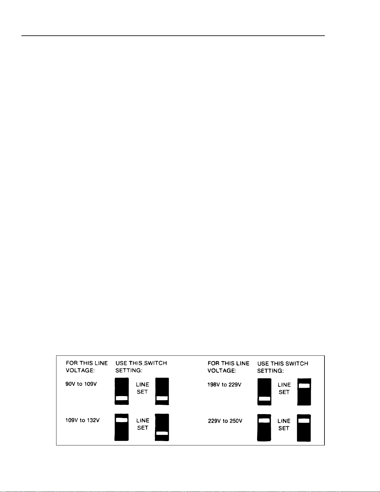
250V maximum) at 50, 60, or 400 Hz. The voltage must be selected by setting the rear
panel LINE SET switches as shown in Figure 2-1. The 8842A automatically senses the
power-line frequency at power-up, so that no adjustment for frequency is necessary.
WARNING
2-2
Figure 2-1. Line Voltage S election Settings
f2-01.wmf
Page 28

2-5. Adjusting the Handle
The handle provides two viewing angles for bench-top use. To adjust its position, pull the
ends out to a hard stop (about 1/4 inch on each side) and rotate it to one of the four stop
positions shown in Figure 2-2. To remove the handle, adjust it to the vertical stop
position and pull the ends all the way out.
2-6. Rack Mounting Kits
You can mount the 8842A in a standard 19-inch rack panel using the accessory rack
mounting kits shown in Figure 2-3. To install the Single Rack Mount Kit, remove the
handle and handle mounting plates, and attach the rack ears with the screws provided
(Figure 2-4). The Dual Rack Mount Kit is installed similarly. (Both kits include mounting
instructions.)
The rear feet may be rotated 180 degrees to clear a narrow rack space.
Operating Instructions
INSTALLATION
2
Figure 2-2. Adjusting the Handle
Figure 2-3. Rack-Mount Kits
f2-02.wmf
f2-03.wmf
2-3
Page 29

8842A
Instruction Manual
Figure 2-4. Installing the Single Rack Mount Kit
2-7. OPERATING FEATURES
2-8. Power-Up Features
When the 8842A is turned on, all display segments light up for about 2 seconds while the
instrument performs an internal self-test of its digital circuitry. The 8842A then assumes
the following configuration:
• VDC function
• Autorange, starting in the 1000V range
• Slow reading rate
• Continuous, internal trigg er
• OFFSET off
• Local (front panel) control
While all display segments are lit during the power-up self-test, you can freeze the
display by pressing the SRQ button. All display segments will then remain lit until you
press any button.
f2-04.wmf
2-4
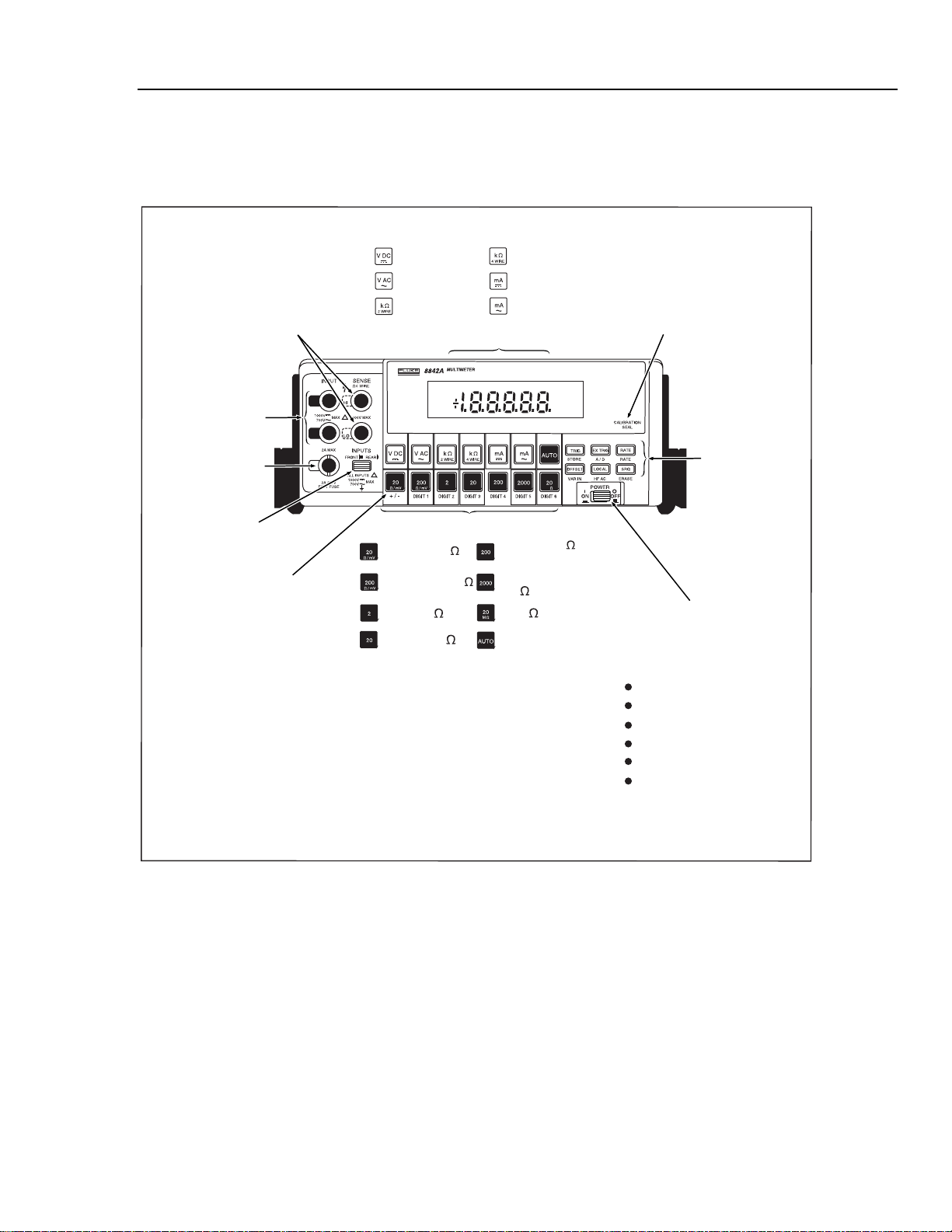
2-9. Front and Rear Panel Features
Front panel features are explained in Figure 2-5. Rear panel features are explained in
Figure 2-6.
The alternate functions embossed below the front pane l range buttons and the spec ia l
feature buttons are enabled by the CAL ENABLE switch. These functions are for use
only when calibrating the instrument. See the Maintenance section for further
explanation.
CAUTION
To avoid accidentally uncalibrating the 8842A, do not press the
CAL ENABLE switch unless calibrating the instrument. Never
cycle power on or off while the CAL ENABLE switch is on.
Page 30
Operating Instructions
OPERATING FEATURES
Note that the VAC and mA AC functions are available only with the True RMS AC
option. If this option is absent, pressing the VAC and mA AC function buttons causes the
8842A to briefly display an error message (ERROR 30).
FUNCTION BUTTONS:
Display
4-Wire Ohms
DC Current
AC Current*
CAL ENABLE switch
enables calibration
mode. (CAUTION! See text.)
HIGH and LO SENSE
Terminals for 4-Wire Ohms Only
DC Volts
AC Volts*
2-Wire Ohms
2
HI and LO
INPUT Terminals
2A INPUT Terminal
(Houses 2A fuse)
FRONT/REAR switch selects
either front or rear inputs.
Calibration Functions
(embossed)
*Available with 8842A-09 True RMS AC only.
Gives error message if option not installed.
!
!
RANGE BUTTON:
20 mV or 20
200 mV or 200
2V or 2 k
20V or 20 k
SPECIAL
FEATURES
M
200V, 200 k or
200 mA dc
1000V dc, 700V ac,
2 M or 2000 mA
20 M
Autorange On/Off **
** For a description of the autorange feature,
see paragraph 2-14.
POWER switch turns 8842A
on or off. Also initiates
power-up self-test and
resets instrument to:
VDC function
Autorange
Slow reading rate
Continuous trigger
OFFSET off
Local (front panel) control
Figure 2-5. Front Panel Features
f2-05_1.wmf
2-5
Page 31

8842A
Instruction Manual
TRIG triggers a new reading.
Enabled in external trigger mode.
M
OFFSET stores the displayed reading as an
offset, which the 8842A subtracts from all
subsequent readings in the function
presently selected. Readings in the other
functions remain unaffected. Pressing
OFFSET again cancels the offset, or stores
a new offset if in a different function.
Reading Rate Slow, Medium
and Fast. Blinks off when a
reading is triggered.
External Trigger
Mode Enabled
Self-Test
Enabled
IEEE-488 Interface
Annunciators
Overrange
EXT TRIG toggles between internal
and external trigger modes
RATE cycles between slow, medium and
fast reading rates. Automatically
selects the optimum filter for each
reading rate.
SRQ generates a service request over the IEEE488 bus if enabled by the SRQ mask (IEEE-488
Interface option only). When pressed for 3
seconds, SRQ initiates diagnostic self-tests.
NOTE: Leave inputs disconnected during selftests or the 8842A may indicate errors.
If the 8842A is in remote, LOCAL returns it to
local control. If the 8842A is in local, the
LOCAL button causes the 8842A to display its
bus address for two and one half seconds.
Ignored if the IEE-488 Interface is not
installed.
Error Condition
Calibration Mode Enabled
Autorange On
Offset On
Function
and Units
Annunciators
2-6
Figure 2-5. Front Panel Features (cont)
f2-05_2.wmf
Page 32

Operating Instructions
OPERATING FEATURES
2
EX TRIG input*
TTL-level,
falling-edge triggered
(internally selectable)
IN OUT
EXT TRIG
10V MAX
JOHN FLUKE MFG. CO., INC.
EVERETT, WA MADE IN U.S.A.
WARNING
GROUNDING CONDUCTOR
IN POWER CORD MUST BE
CONNECTED TO ENSURE
PROTECTION FROM
ELECTRICAL SHOCK
Rear feet rotate
for rack mounting
SAMPLE COMPLETE output
TTL-level. Normally high,
pulsed low when samples for
a reading are completed*
TALK ONLY and IEEE-488
ADDRESS Selection Switches*
TTL LEVELS
SHELL NOT
GROUNDED
15V MAX
SAMPLE
COMPLETE
PATENTS PENDING
CAUTION
FOR FIRE PREVENTION
REPLACE ONLY WITH
1/4 A SLOW FUSE, 100/120v
1/8 A SLOW FUSE, 220/240V
ADDRESS
A5
TALK
ONLY
IEEE-05
AC-09
!
REMOVE GROUNDING SCREW BEFORE REMOVING COVER
Line V oltage
Selection Switches
Serial Number
A3
A1
240V
LINE FUSE
250V
220V
120V
100V
LINE
SET
Power-Line Fuse
IEEE STD-488 PORT
SH1, AH1, T5, L4, SR1, RL1,
DC1, DT1, PP0, C0, E1
20 VA 50/60/400 Hz
Power-Line Cord
Connector
IEEE-488 Interface
Bus Connector*
HIGH and LO SENSE
Terminals for 4-Wire
Ohms Only
INPUT SENSE
HI
1000V
700V
LO
1000V
700V
MAX
ALL
INPUTS
!
300V MAX
MAX
HI and LO INPUT
Terminals
4 WIRE
!
*Available with IEEE-488 Interface only.
Otherwise, the upper portion of the rear panel is
covered with an insert as shown at right.
CAUTION: The rear panel insert is attached from
inside the case. Refer to Section 8 for instructions
on removing it.
JOHN FLUKE MFG. CO., INC.
EVERETT, WA MADE IN U.S.A.
WARNING
GROUNDING CONDUCTOR
IN POWER CORD MUST BE
CONNECTED TO ENSURE
PROTECTION FROM
ELECTRICAL SHOCK
PATENTS PENDING
Rear Panel Insert
LINE FUSE
250V
240V
220V
120V
100V
20 VA 50/60/400 Hz
IEEE-05
AC-09
CAUTION
FOR FIRE PREVENTION
REPLACE ONLY WITH
1/4 A SLOW FUSE, 100/120v
1/8 A SLOW FUSE, 220/240V
LINE
SET
!
REMOVE GROUNDING SCREW BEFORE REMOVING COVER
Figure 2-6. Rear Panel Features
INPUT SENSE
HI
1000V
MAX
700V
LO
1000V
700V
!
ALL
INPUTS
4 WIRE
300V MAX
MAX
!
f2-06.wmf
2-7
Page 33

8842A
Instruction Manual
2-10. Display Features
2-11. Error Messages
The 8842A features a vacuum fluorescent display with a numeric field and annunciators.
The annunciators are explained in Figure 2-5.
If the 8842A detects an operator error or an internal failure, it displays an error message
for about 2-1/2 seconds and then resumes normal operation. During this time, the front
panel buttons are ignored. The error message consists of the ERROR annunciator and a
two-digit error code. (See Figure 2-7.) Error codes are explained in Table 2-1.
If the FRONT/REAR switch is set to the REAR position while the mA DC or mA AC
function is selected, ERROR 31 is displayed. In this case the error message is displayed
until you return the switch to the FRONT position or select another function.
Figure 2-7. Typical Error Messages
f2-07.wmf
2-8
Page 34

Operating Instructions
OPERATING FEATURES
Table 2-1. Error Codes
ERROR
CODE
ANALOG SELF-TEST ERRORS OPERATION ERRORS
1 200 VAC, Zero 30 AC funtions availible only with 8842A-09 True
2 700 VAC, Zero 31 mA AC or mA DC funtion selected while
3 mA AC, Zero 32
4 mA DC, Zero 40 Computed calibration constant out of
5 200 VDC, Zero 41 Calibration input out of acceptable range.
6 1000 VDC, Zero 42 Calibration memory write error. (Probably a
7 1000 VDC, Zero 50
8 20 VDC + 20MΩ 51 Calibration command not valid unless
9 20 VDC + 2000 kΩ 52 Command not valid at this time.
10 2 VDC + 2000 kΩ 53 Invalid calibration value in Put command.
11 200Ω, Overrange 54 Command not valid in calibration verification.
12 2 kΩ, Overrange 56 Variable inputs not allowed during A/D
13 20 kΩ, Overrange 60 Device-dependent commands not valid
14 200 kΩ, Overrange 71 Syntax error in device-dependent command
15 1000 VDC + X10 T/H + 20 MΩ 72 Guard crossing error detected by out Guard
16 200 VDC + 200 kΩ 73
17 200 VDC + 20 kΩ 77 IEEE-488 Interface self-test error.
DIGITAL SELF-TEST ERRORS
25 In-Guard µC Internal RAM
26 Display RAM
27 In-Guard µC Internal Program Memory
28 External Program Memory
29 Calibration Memory
NOTE: See the Maintenance section for a detailed description of self-tests.
MEANING ERROR CODE MEANING
RMS AC option.
REAR inputs selected.
OFFSET selected with reading unavailible for
overrange.
range.(Previous cal may be wrong or there
may be a hardware problem.)
Check that input is correct. (Previous cal may
be wrong or there may be a hardware
problem.)
hardware problem.)
Guard crossing error detected by In-Guard
µC.
calibration mode is enabled.
(Example: Sending a negative value during
ac calibration.)
calibration.Use prompted value.
during self-tests.
string.
µC.
Guard crossing error detected at power on or
CAL ENABLE switch on at power on.
2
2-9
Page 35

8842A
Instruction Manual
2-12. Overrange Indication
2-13. Diagnostic Self-Tests
An input is overrange if it exceeds the full scale of the selected range. In most ranges, the
8842A indicates an input is overrange by lighting the OVER annunciator and showing a
"1" on the display. (See Figure 2-8.) The sign, the position of the decimal point, and the
other annunciators are not affected.
As a safety feature, the 8842A treats the 1000V dc and 700V ac rangesdifferently. In
these ranges, the 8842A indicates when the input exceeds the input overload limit of
1000V dc or 700V ac, respectively, by lighting the OVER annunciator and flashing the
display. Readings are still displayed.
The 8842A features diagnostic self-tests which check both the digital and analog circuitry
in the instrument. The self-tests consist of 21 analog tests followed by the in-guard
program memory, calibration memory, and display self-tests. To initiate the self-tests,
press the SRQ button for 3 seconds. The instrument can be stopped in any of the test
configurations by pressing the SRQ button while the test number is displayed. Press any
button to continue the tests.
During the test, the TEST annunciator lights, and the numeric field displays the number
of each analog test as it is performed. Then all display segments light up while the
instrument performs the in-guard program memory, calibration memory, and display selftests. The 8842A then returns to the power-up configuration. The self-tests are described
in greater detail in the Maintenance section.
The inputs must be left disconnected while the self-tests are performed or
the 8842A may indicate that errors are present.
If the 8842A detects an error, it displays an error message for about 2-1/2 seconds. (Error
codes 01 through 29 correspond to the self-tests.) If self-test errors are displayed even
when the input terminals are disconnected, there may be a hardware problem in your
8842A. In that event, refer to the Maintenance section or contact your local Fluke
representative.
2-14. Ranging
Measurement ranges can be selected using either autorange (by pressing the AUTO
button) or manual range (by pressing another range button). The 8842A displays explicit
units in every range, so that the display may be read directly.
2-15. AUTORANGE
In autorange, the 8842A goes to a higher range when the input exceeds full scale (199999
counts), and goes to a lower range when the input falls below 9% of full scale (18000
counts). While the instrument changes range , the numer ic field on the d isplay is b lank ed
until a new reading is completed. However, the decimal point and units annunciators
always indicate what range the instrument is in.
Pressing the AUTO button when the instrument is already in autorange toggles the
8842A from autorange to manual range. This causes the instrument to remain locked in
the present range.
NOTE
2-10
The 8842A autoranges up to the highest ranges in all functions, down to the 200 mV
range in the VDC and VAC functions, and down to the 200Ω range in the ohms
functions. To select the 20 mV dc, 20Ω, or 200 mA dc range, press the respective range
button (or send the respective range command, if using the IEEE-488 option).
Page 36

2-16. MANUAL RANGE
In manual range, the 8842A remains fixed in the selected range until you select another
range or press AUTO. If you select a range which is not valid for the present function, or
select a function which is not valid for the present range, the 8842A selects the nearest
valid range. For example, if the 8842A is in the VDC function and you press the 20 MΩ
button, the 8842A selects the 1000V range.
The range buttons have no effect in the mA AC functions, since all measurements in
these functions are made in the 2000 mA range.
2-17. Triggering
Triggering causes the 8842A to execute a measurement cycle and display the result.
During each measurement cycle, the instrument samples the input a number of times and
then averages the samples to compute a reading. The number of samples averaged for
each reading depends upon the reading rate.
Each time a reading is triggered, the rate annunciator (S, M, or F) blinks off. In the fast
reading rate, the F annunciator flashes so rapidly it appears to be almost constant.
How the 8842A is triggered depends on whether the continuous trigger mode or external
trigger mode is selected. Pressing the EX TRIG (external trigger) button toggles the
8842A between the two modes.
Operating Instructions
OPERATING FEATURES
2
2-18. CONTINUOUS TRIGG ER MODE
In the continuous trigger mode, readings are triggered by a continuous, internal trigger.
The rate of the trigger is set by the RATE button.
2-19. EXTERNAL TRIGGER MODE
In the external trigger mode, readings are triggered by pressing the TRIG button. If the
IEEE-488 Interface option is installed, readings can also be triggered by remote
commands or by using the rear panel external trigger (EXT TRIG) connector. (See the
Options and Accessories section.)
In the external trigger mode, pressing any front panel button blanks the numeric field on
the display until a new measurement is triggered. This ensures that all readings
correspond to the instrument configuration indicated by the display annunciators. The
blanking also occurs in the continuous trigger mode, but usually isn’t noticed because
new measurements are triggered automatically.
The TRIG button does not trigger readings in the continuous trigger mode.However, it
does blank the last reading to acknowledge a button was pressed.
2-20. Reading Rates and Noise Rejection
The RATE button allows you to optimize either measurement speed or noise rejection.
The 8842A uses both analog and digital filtering to allow measurements in the presence
of unwanted environmental noise (especially line-related noise). However, since filtering
introduces a delay in response to a change in the input signal, there is an inherent tradeoff between noise rejection and measurement speed.
The instrument has three reading rates: slow (S) and medium (M), with a 5-1/2 digit
display, and fast (F), with a 4-1/2 digit display. To provide optimum combinations of
measurement speed and noise rejection, the RATE button allows control of both the
internal trigger rate and the degree of filtering. The same degree of filtering is used in
both the continuous and external trigger modes. In the 20 mV, 20Ω, and 200 mA dc
ranges, use of slow (S) filter provides maximum noise rejection.
2-11
Page 37

8842A
Instruction Manual
2-21. Au tomatic Se ttling Time Delay
In the continuous trigger mode, the actual number of readings displayed per second for
each reading rate is determined by the line-power frequency. At power-up, the 8842A
senses the line-power frequency and adjusts the analog-to-digital converter timing
characteristics for optimum normal-mode noise rejection. The resulting reading rates are
shown in the specifications in Section 1.
When the external trigger mode is selected, the 8842A automatically inserts a delay after
receiving a trigger signal, but before starting the first input sample. The delay is just long
enough so that the reading will be correct (within a specified number of counts of the
final value) even if the trigger signal occurs as the input makes a step change between
zero and full scale (10,000 counts and full scale in the ac functions).The length of the
delay depends on the range, function, and reading rate, as shown in the specifications in
Section 1. The delay is enabled only in the external trigger mode. It can be turned off
with a remote command over the IEEE-488 interface bus to accommodate special timing
considerations.
Figure 2-8. Overrange Indication
2-22. External Trigger Input (Option -05 Only)
The rear panel EXT TRIG input is a TTL-level input which can be used to trigger
measurements when the 8842A is in the external trigger mode. A measurement is
triggered on the falling edge of the input. Since the EXT TRIG input is pulled high
internally, it can also be controlled by a normally open switch. A measurement is
triggered when the switch is closed. For special applications using the IEEE-488
Interface, the automatic setting time delay can be disabled using remote commands. (See
Section 3.) Refer to Section 1 for timing details.
The polarity of the EXT TRIG input can be reversed by changing internal jumpers. Refer
to the Maintenance section for instructions.
2-23. Sample Complete Output (Option -05 Only)
The SAMPLE COMPLETE output indicates when analog input sampling for a reading is
completed. The output is a TTL-level signal which is pulsed low for approximately 2.5
µs when the input-sampling portion of the A/D conversion is completed. The signal is
useful for interfacing with other equipment when the 8842A is used in external trigger
mode in an instrumentation system. For example, the SAMPLE COMPLETE output
could be used to advance a scanner to the next channel.
f2-08.wmf
2-12
Page 38

2-24. MAKING MEASUREMENTS
2-25. Input Overload Protection Limits
WARNING
TO AVOID SHOCK HAZARD AND/OR INSTRUMENT DAMAGE,
DO NOTAPPLY INPUT POTENTIALS THAT EXCEED THE INPUT
OVERLOAD LIMITS SHOWN IN TABLE 2-2.
The 8842A is protected against input overloads up to the limits shown in Table 2-2.
Exceeding these limits may damage the instrument and/or pose a shock hazard.
Table 2-2. Input Overload Limits
FUNTION CONNECTORS MAXIMUM INPUT
VDC INPUT HI and LO: 1000 dc
MA DC 2A INPUTand INPUT LO: 2000mA
2 WIRE/4 WIRE kΩ INPUT HI and LO: 300V rms
Operating Instructions
MAKING MEASUREMENTS
2
SENSE HI and LO: 300V rms
VAC INPUT HI and LO: 700V rms, 1000V peak, or 2 x 10
V-Hz (whichever is less)
MA AC 2A INPUT and INPUT LO: 2000 mA rms
All Funtions Any terminal to earth: 1000V dc or peak ac
2-26. Measuring Voltage and Resistance
To measure voltage or resistance, select the desired function and connect the test leads as
shown in Figure 2-9. Resistance can be measured in either the 2-wire or 4-wire
configuration.
2-27. Measuring Current
To measure current, select the desired function and connect the test leads as follows:
1. Turn off power in the circuit to be measured (Figure 2-10).
2. Break the circuit (preferably on the ground side to minimize the common mode
voltage), and place the 8842A in series at that point.
3. Turn on power in the circuit, and read the display.
4. Turn off power in the circuit, and disconnect the 8842A.
2-28. Current Fuse Protection
The 2A input terminal is protected from overloads by a 2A, 250V fuse which is
accessible from the front panel, and by an internal 3A, 600V fuse. If either fuse blows,
the 8842A will respond as though the input were zero.
7
WARNING
TO AVOID ELECTRIC SHOCK, REMOVE THE TEST LEADS
BEFOREREPLACING THE FRONT PANEL FUSE.
2-13
Page 39

8842A
Instruction Manual
2-29. Offset Measurements
To replace the front panel fuse, first remove the test leads. Then press in the lip of the 2A
input terminal slightly and rotate it 1/4-turn counterclockwise. Spring tension will force
the fuse and fuse holder out of the front panel. The internal 3A fuse should be replaced
only by qualified service personnel.
WARNING
WHEN THE OFFSET FEATURE IS IN USE, DISPLAYED
READINGS ARE RELATIVE AND MAY NOT INDICATE THE
PRESENCE OF DANGEROUS POTENTIALS AT THE INPUT
CONNECTORS OR TEST LEADS. USE CAUTION TO AVOID
ELECTRIC SHOCK OR INSTRUMENT DAMAGE.
The OFFSET feature allows you to store a reading as a relative reference value. When the
OFFSET button is pressed, the 8842A stores the present reading and displays subsequent
measurements as the difference between the measured value and the stored reading. The
OFFSET annunciator is lit whenever an offset is in use.
The OFFSET feature may be used in all functions. Since the display represents a numeric
difference, it always has a sign, even in the resistance and ac functions.
The offset can be canceled by pressing the OFFSET button again, in which case the
OFFSET annunciator disappears from the display. The offset can also be canceled by
storing an offset in another function. If a reading is overrange or unavailable when the
OFFSET button is pressed, the 8842A indicates ERROR 32 and does not store the offset.
If you change functions while an offset is stored, the OFFSET annunciator disappears and
the offset temporarily disappears. However, when you return to the original function, the
offset is restored (and the OFFSET annunciator reappears) unless a new offset was
established in another function. Note that the input overload limits are not changed by the
use of the offset feature. However, the display flashes if the 8842A is in the 1000V dc or
700V ac ranges and the input exceeds 1000V dc or 700V ac, respectively.
While an offset is enabled, the 8842A indicates an overrange condition if either of the
following conditions occur:
• The input signal is overrange
• The calculated reading is overrange
For example, suppose the instrument is in the 20V range of the VDC function and you
store an offset of +15V. The maximum positive voltage reading that can be displayed
without overranging is +4.9999V, which is actually a +19.9999V input signal. The
maximum negative voltage reading that can be displayed without overranging is -
19.9999V, which is actually a -4.9999V input signal. You can measure a greater range of
voltages by selecting a higher range.
2-14
When in autorange, the 8842A selects the range appropria te for the inpu t signa l,
regardless of any stored offset. If, for example, a +10V offset is stored, and a +1V input
is applied, the 8842A will autorange to the 2V range and display an overrange condition
since it cannot display -9V on the 2V range. Manual range control could be used to lock
the 8842A into the 20V range in this case.
Applications of the offset feature include correcting for test lead resistance in 2-wire
resistance measurements, nulling offset currents or voltages, measuring voltage
deviations, and matching resistors.
Page 40

Operating Instructions
EXTERNAL CLEANING
2
Figure 2-9. Measuring Voltage and Resistance
Figure 2-10. Measuring Current
2-30. EXTERNAL CLEANING
WARNING
TO AVOID ELECTRIC SHOCK OR INSTRUMENT DAMAGE,
NEVER GET WATER INSIDE THE CASE. TO AVOID
INSTRUMENT DAMAGE, NEVER APPLY SOLVENTS TO THE
INSTRUMENT.
f2-09.wmf
f2-10.wmf
Should the 8842A case require cleaning, wipe the instrument with a cloth that is lightly
dampened with water or a mild detergent solution.
2-15
Page 41

8842A
Instruction Manual
2-16
Page 42

Chapter 3
Remote Programming
Title Page
3-1. INTRODUCTION................................................................................3-3
3-2. CAPABILITIES...................................................................................3-3
3-3. BUS SET-UP PROCEDURE...............................................................3-3
3-4. AN OVERVIEW OF REMOTE OPERATION...................................3-4
3-5. A NOTE ABOUT EXAMPLES...........................................................3-6
3-6. DEVICE-DEPENDENT COMMAND SET ........................................3-6
3-7. Bn (Offset Commands)....................................................................3-9
3-8. Cn (Calibration Commands)............................................................3-9
3-9. Dn (Display Commands)..................................................................3-9
3-10. Fn (Function Commands) ................................................................3-10
3-11. Get Commands.................................................................................3-10
3-12. G0 (Get Instrument Configuration)..................................................3-12
3-13. G1 (Get SRQ Mask).........................................................................3-12
3-14. G2 (Get Calibration Prompt)............................................................3-12
3-15. G3 (Get User-Defined Message)......................................................3-13
3-16. G4 (Get Calibration Status)..............................................................3-13
3-17. G5 (Get IAB Status).........................................................................3-14
3-18. G6 (Get YW Status).........................................................................3-14
3-19. G7 (Get Error Status).......................................................................3-14
3-20. G8 (Get Instrument Identification)...................................................3-15
3-21. N (Numeric Entry Command)..........................................................3-15
3-22. Put Commands.................................................................................3-15
3-23. P0 (Put Instrument Configuration)...................................................3-15
3-24. P1 (Put SRQ Mask)..........................................................................3-16
3-25. P2 (Put Calibration Value)..............................................................3-16
3-26. P3 (Put User-Defined Message)......................................................3-17
3-27. Rn (Range Commands)....................................................................3-17
3-28. Sn (Reading Rate Commands).........................................................3-17
3-29. Tn (Trigger Mode Commands)........................................................3-18
3-30. Wn (Terminator Commands)...........................................................3-19
3-31. X0 (Clear Error Register Command)...............................................3-19
3-32. Yn (Suffix Commands)....................................................................3-19
3-33. Z0 (Self-Test Command).................................................................3-19
3-34. (Device-Clear Command)................................................................3-20
3-1
Page 43

8842A
Instruction Manual
3-35. ? (Single-Trigger Command)...........................................................3-20
3-36. INPUT SYNTAX.................................................................................3-20
3-37. Definitions........................................................................................3-21
3-38. Input Processing...............................................................................3-21
3-39. Syntax Rules ....................................................................................3-23
3-40. OUTPUT DATA..................................................................................3-24
3-41. Loading Output Data........................................................................3-24
3-42. Types of Output Data.......................................................................3-25
3-43. Numeric Data and Error Messages...................................................3-25
3-44. MEASUREMENT DATA...........................................................3-25
3-45. OVERRANGE INDICATION ....................................................3-26
3-46. ERROR MESSAGES..................................................................3-26
3-47. Status Data .......................................................................................3-26
3-48. Output Priority .................................................................................3-26
3-49. SERVICE REQUESTS........................................................................3-27
3-50. The Serial Poll Register ...................................................................3-27
3-51. The SRQ Mask.................................................................................3-28
3-52. INTERFACE MESSAGES..................................................................3-29
3-53. Address Messages............................................................................3-29
3-54. Universal Commands.......................................................................3-29
3-55. Addressed Commands......................................................................3-30
3-56. TALK-ONLY MODE..........................................................................3-30
3-57. REMOTE CALIBRATION..................................................................3-31
3-58. TIMING CONSIDERATIONS............................................................3-31
3-59. IMMEDIATE MODE COMMANDS..................................................3-31
3-60. EXAMPLE PROGRAMS....................................................................3-32
3-2
Page 44

This section contains programming instructions for use with the IEEE-488
Interface (Option -05). For installation instructions, refer to the Options
and Accessories section.
3-1. INTRODUCTION
The IEEE-488 Interface turns the 8842A into a fully programmable instrument for use
with the IEEE Standard 488-1978 interface bus (IEEE-488 bus). With the IEEE-488
Interface, the 8842A can become part of an automated instrumentation system. The
8842A can be under complete, interactive control from a remote bus controller; or it can
be set to the talk-only mode, connected to a data logger or printer, and dedicated to a
single task.
This manual assumes you know the basics of the IEEE-488 interface bus. For an
introduction to the bus, request Fluke Application Bulletin AB-36, "IEEE Standard 4881978 Digital Interface for Programmable Instrumentation."
3-2. CAPABILITIES
The IEEE-488 Interface provides remote control of all front panel controls except for the
POWER, CAL ENABLE, and FRONT/REAR switches. Other features include:
NOTE
Remote Programming
INTRODUCTION
3
• A simple and predictable command set
• Fast measurement throughput
• Full talk/listen capability, including talk-only operation
• Full serial poll capability, with bit-maskable SRQ
• Full remote/local capability, including local lockout
• EXTERNAL TRIGGER and SAMPLE COMPLETE connectors
• Remote calibration
• Programmable trigger sources, including two bus triggers
• Informative output suffix (suppressible)
• Selectable output termina tor s
The 8842A supports the following interface function subsets: SH1, AH1, T5, L4, SR1,
RL1, DC1, DT1, E1, PP0, and C0.
3-3. BUS SET-UP PROCEDURE
To set up the 8842A on the IEEE-488 bus, proceed as follows:
1. Turn the 8842A POWER switch OFF and set the 8842A IEEE-488 address using the
rear panel IEEE-488 address switches shown in Figure 3-1.
2. With the 8842A POWER switch OFF, plug the IEEE-488 cable into the 8842A rear
panel IEEE-488 connector.
3. Switch on the 8842A.
3-3
Page 45

8842A
Instruction Manual
A
D
D
R
E
S
S
00 0 0 0000 11 001011 22 0 10110
01 0 0 0001 12 001100 23 0 10111
A5 A4 A3 A2 A1 A
T
A
L
K
O
N
L
Y
A5 A4 A3 A2 A1
A5 A4 A3 A2 A1 A
T
A
D
L
D
K
R
E
O
S
N
S
L
Y
D
D
R
E
S
S
T
A
L
K
O
N
L
Y
02 0 0 0010 13 001101 24 0 11000
03 0 0 0011 14 001110 25 0 11001
04 0 0 0100 15 001111 26 0 11010
05 0 0 0101 16 010000 27 0 11011
06 0 0 0110 17 010001 28 0 11100
07 0 0 0111 18 010010 29 0 11101
08 0 0 1000 19 010011 30 0 11110
09 0 0 1001 20 010100 31 Not allowed
10 0 0 1010 21 010101 1 XXXXXTALK
ONLY
Figure 3-1. IEEE-488 Address Selection
X = setting does not matter
f3-01.wmf
Whenever the 8842A is in the local state, the IEEE-488 address can be displayed on the
front panel by pressing the LOCAL button.
3-4. AN OVERVIEW OF REMOTE OPERATION
An overview of remote operation is presented in the block diagram in Figure 3-2. Each
block represents a register, buffer, etc., contained in the 8842A. The status registers in the
center column indicate the instrument’s status, including its function, range, reading rate,
etc. The input buffer receives data from the IEEE-488 bus. The output buffer receives
data from the blocks to its left, and sends data on to the IEEE-488 bus.
3-4
Page 46

Remote Programming
AN OVERVIEW OF REMOTE OPERATION
3
Figure 3-2. Remote Operation Block Diagram
f3-02.wmf
3-5
Page 47

8842A
Instruction Manual
3-5. A NOTE ABOUT EXAMPLES
Information is transferred between blocks by device-dependent commands. Each
command is shown next to an arrowhead which indicates the resulting information
transfer. For example, Put command P0 takes a number from the input buffer and stores it
in the primary status registers. Likewise, Get command G0 gets the content of the
primary status registers and copies it into the output buffer.
In the examples in this manual, device-dependent commands are shown enclosed within
quotation marks, as they would be entered in Fluke BASIC. For clarity, the commands
are also separated by spaces. However, the spaces are are not necessary and may be
omitted.
Example Explanation
"* F3 R1 S1 T2" This example is equivalent to "*F3R1S1T2" or
"*,F3,R1,S1,T2".
Using the Fluke 1722A Instrument Controller, these commands might be written into a
BASIC program as shown in Figure 3-3. Examples using other controllers are given at
the end of this section.
3-6
Figure 3-3. Typical Command String
f3-03.wmf
Examples of 8842A output data show the terminators CR and LF. The terminator EOI is
not shown because it is a uniline message. However, the terminators CR, LF, and EOI are
all selectable using the Write commands.
For reference, the ASCII and IEEE Std 488-1978 bus codes are shown at the back of this
section.
3-6. DEVICE-DEPENDENT COMMAND SET
Device-dependent commands are the heart of 8842A remote control. They tell the 8842A
how and when to make measurements, when to put data on the bus, when to make service
requests, etc. Commands which correspond directly to the front panel controls or display
are shown in Figure 3-4. The complete set of device-dependent commands is listed in
Figure 3-5. The commands may be entered using either upper- or lower-case letters. See
Table 6-15 for conditions under which certain commands are not valid.
Page 48

Remote Programming
DEVICE-DEPENDENT COMMAND SET
TRIGGER COMMANDS
? Trigger Measurement
GET Trigger and Execute
TRIGGER MODE COMMANDS
T0 Continuous Trigger
T1-T4 External Trigger
3
DISPLAY COMMANDS
D0 Normal Display
D1 Blank Display
Sensed
by G5
FUNCTION COMMANDS
F1 VDC
F2 VAC
F3 2 Wire kΩ
F4 4 Wire kΩ
F5 mA DC
F6 mA AC
SUFFIX COMMANDS
Y0 Disable Suffix
Y1 Enable Suffix
RANGE COMMANDS
R0 Autorange On
R1 200 mV, 200Ω
R2 2V, 2 kΩ
R3 20V, 20 kΩ
R4 200V, 200 kΩ, 200 mA
R5 1000V dc, 700V ac,
2 MΩ, 2000 mA
R6 20 MΩ
R7 Autorange Off
R8 20 mV, 20Ω
READING RATE
COMMANDS
S0 Slow
S1 Medium
S2 Fast
M
SELF-TEST
COMMANDS
Z0 Begins Self-Tests
GTL Go To Local
DEVICE-CLEAR
COMMANDS
*Reset 8842A to
power-up state
OFFSET COMMANDS
B0 Offset Off
B1 Offset On
Figure 3-4. Commands Which Correspond to the Front Panel
f3-04.wmf
3-7
Page 49

8842A
Instruction Manual
FUNCTON COMMANDS TERMINATOR COMMANDS
F1 VDC (Default) W0 E nabl e CR LF EOI (Def ault)
F2 VAC W1 E nabl e CR LF Only
F3 2 WIRE kΩ W2 E nabl e CR EOI Only
F4 4 WIRE kΩ W3 E nabl e CR Only
F5 M A DC W4 Enable LF EOI Only
F6 M A AC W5 Enable LF Only
RANGE COMMANDS W7 Disable All Output Terminators
R0 Autorange CLEAR COMMANDS
R2 2V, 2 kΩ * Device Clear (Resets 8842A to def ault
R3 20V, 20 kΩ X0 Clear Error Register
R5 1000V dc, 700V ac, 2 MΩ, 2000 mA SINGLE-TRIGGER COMMAND
R6 20 mΩ ? Trigger Measurement
R8 20mV, 20Ω GET COMMANDS
READING RATE COMMANDS G0 Get Instrument Configuration (F,R, S, and
S0 Slow (Default) G1 Get SRQ Mask
S1 Medium G2 Get Calibration Input Prompt
S2 Fast G3 Get User-Defined Message
TRIGGER MODE COMMANDS G4 Get Calibration Status
COMMAND TRIGGER
TO (Default) Internal Disabled - G6 Get YW Status (Suffix
T1 External Enabled On G7 Get Error Status
T2 External Disabled On G8 Get Instrument Identification
T3 External Enabled Off Note: G2 v al i d only in calibration mode.
T4 External Disabled Of f PUT COMM ANDS
Note: Delay is enabled by entering EX TRIG mode while in local. P0 Put Instrument Configuration (F,R,S,
OFFSET COMMANDS P1 Put SRQ Mask
B0 P2 Put Variable Calibration Value
B1 P3 Put User-Defined Message
DISPLAY COMMANDS Note: P2 and P3 valid only in calibration
D0 Offset Off (Default) PUT COMMAND FORMAT
D1 Offset On N <value> P0
SUFFIX COMMANDS N <value> P1
Y0 Normal Display (Default ) N < value> P2
Y1 Blank Display P3 < 16 ASCII characters>
MODE
REAR PANEL
TRIGGER
SETTLING
DELAY
conditions)
T)
G5 Get IAB Status (input F/R, Autorange
On/Off, Offset On/Off)
Enabled/Disabled, Terminator
Selection)
and T)
mode.
3-8
Figure 3-5. Device-Dependent Command Set
Page 50

Device-dependent commands are device-dependent messages. For the 8842A to receive
them, they must be sent over the IEEE-488 bus when the 8842A is in remote and has
been addressed as a listener.
The following paragraphs describe the device-dependent commands in alphabetical order.
Special characters (* and ?) are described last.
3-7. Bn (Offset Commands)
The Offset commands duplicate the function of the front panel OFFSET button. When
the 8842A receives the B1 command, the 8842A stores the present reading as an offset
for the present function. The B0 command cancels the offset. As with front panel
operation, only one offset is allowed at a time.
The offset status (not the offset value) can be read using the G5 command. The 8842A
defaults to B0 on both power-up and on any device-clear command (*, DCL, or SDC).
3-8. Cn (Calibration Commands)
The command string "C3 C0" erases the entire calibration
memory. A complete calibration must then be performed.
CAUTION
Remote Programming
DEVICE-DEPENDENT COMMAND SET
3
The Calibration commands allow the 8842A to be calibrated under remote control.
Commands C0, C1, and C2 duplicate the front panel calibration functions STORE, A/D,
and HF AC, respectively. For a complete description of remote calibration, see the
Maintenance section of this manual.
For the 8842A to accept these commands, the 8842A must be in the calibration mode
(enabled by pressing the front panel CAL ENABLE switch). Otherwise, the commands
generate an error message.
3-9. Dn (Display Commands)
The Display commands allow the user to blank the numeric field in the 8842A front
panel display. The D0 command causes the display to operate normally, and is the default
on power-up and upon any device-clear command (*, DCL, or SDC).
The D1 command blanks the numeric field in the display. The annunciators remain
active, and all of the annunciators still flash if the input exceeds 1000V dc or 700V ac in
the respective ranges. The D1 command is used for best performance when high IEEE488 Interface Data rates are required.
3-9
Page 51

8842A
Instruction Manual
3-10. Fn (Function Commands)
3-11. Get Commands
The function commands duplicate the front panel function buttons. The 8842A defaults to
F1 on power-up and on any device-clear command (*, DCL, or SDC). If F0 is sent to the
8842A, it is internally converted to F1. The function setting can be read using the G0
command.
As with the front panel commands, selecting F6 automatically selects the 2000 mA range
(R5). If the instrument is in range R8, commanding F5 automatically selects the 200 mA
range (R4). If the instrument is in R1 through R6, commanding F5 automatically selects
the 2000 mA range (R5). If the 8842A is in a resistance function (F3 or F4) and in R6,
selecting any other function automatically selects R5. If the 8842A is in range R8 and F2
or F3 is commanded, range R1 is selected.
Example Explanation
"F3" Selects 2 WIRE kΩ function; it does not affect any other settings.
"* F6" Selects mA AC function and 2000 mA range. Resets all other settings to
default.
The Get commands "get" information from the 8842A for the cont ro lle r. Each Get
command loads the output buffer with an output string in the format shown in Figure 3-6.
Status data (the output from Get commands G0, G1, G3, G4, G5, G6, G7 and G8) is
interpreted as shown in Table 3-1. The Get commands should not be confused with the
interface message GET (Group Execute Trigger).
3-10
Figure 3-6. Output Data Format
f3-06.wmf
Page 52

DEVICE-DEPENDENT COMMAND SET
Table 3-1. Status Data
OUTPUT
COMMAND
G0 Frst F = 1 – 6 as in Funtion commands (Fn)
G1 nn nn = 00 for SRQ disabled (default)
G3 aaaaaaaaaaaaaaaa 16 user-defined ASCII characters
G4 10vm V = 0 Not in cal verification
STRING MEANING
9 for Self-Test
r = 1 – 6 and 8 in Range commands (Rn)
s = 0 – 2 as in Reading Rate commands (Sn)
t = 0 – 4 as in Trigger Mode commands (Tn)
01 for SRQ on overrange
04 for SRQ on front panel SRQ
08 for SRQ on cal step complete
16 for SRQ on data availible
32 for SRQ on any error
Note: SRQ mask values may be added for combinations.Example:
33 for SRQ on overrange or any error.
1 Cal verifi cation
m = 0 Not in calibration mode
Remote Programming
3
1 A/D calibration
2 Offset and gain calibration
4 HF AC calibration
G5 1iab I = 0 FRONT inputs selected
1 REAR inputs selected
a = 0Autorange on
1 Autorange off (manual range)
b = 0 OFFSET off
1 OFFSET on
G6 10yw Y = 0 output suffix disabled
1 output suffix enabled
w = 0 – 7 as in Terminator commands (Wn)
G7 10nn nn represents error code (See Table 2-1)
G8
FLUKE,
mmmmm,
0, Vn.n
Mmmmm = 8842A
Vn.n = IEEE-488 Interface software version number
The output data from some Get commands starts with a leading 1 or 10. This prevents the
controller from suppressing leading zeroes and gives a uniform four-character length to
all instrument configuration data (the data from Get commands G0, G4, G5, G6, and G7).
The Get commands are described further in the following paragraphs. For more
information about output data, see paragraph 3-39.
3-11
Page 53

8842A
Instruction Manual
3-12. G0 (Get Instrument Configuration)
The G0 command copies the 8842A function, range, reading rate, and trigger mode into
the output buffer in the format shown in Figure 3-6. The four digits returned represent the
arguments for the equivalent F, R, S, and T commands, as shown in Table 3-1. An
example output string follows.
Example Explanation
3410 CR LF 3: F3 (2 WIRE kΩ function)
4: R4 (200 kΩ range)
1: S1 (Medium reading rate)
0: T0 (Continuous trigger)
The second digit, which can vary from 1 to 6, indicates what measurement range the
8842A is in regardless of whether the 8842A is in autorange or manual range.
The output string from a G0 command is acceptable as an argument for an "N" command.
This allows you to configure the 8842A from the front panel and then record the
configuration over the bus for future use with a P0 command. However, 9mmm (meaning
self-test) can not be used with the P0 command.
3-13. G1 (Get SRQ Mask)
The G1 command copies the present SRQ mask into the output buffer in the format
shown in Figure 3-6. The SRQ mask values are explained in Table 3-1. An example
output string follows. For more about the SRQ mask, see paragraph 3-47.
Example Explanation
33 CR LF Enable SRQ on any error or overrange
3-14. G2 (Get Calibration Prompt)
The G2 command is used when calibrating the 8842A under remote control. The
command loads the output buffer with a calibration prompt that represents the input
expected at the analog inputs. The calibration promp t is form atted as a sign ed decim a l
with exponent, as shown in Figure 3-6. The suffix may be enabled with the Y1 command.
Example output strings follow.
Examples Explanation
+1.00000E+0 CR LF Calibration prompt
+190.000E-3 CR LF Calibration prompt
+1.90000E+0, VDC CR LF Calibration prompt (Suffix enabled)
If an error has occurred, the G2 command loads the output buffer with an error message
instead of the prompt. (See paragraph 3-39.)
The G2 command is valid only when the calibration mode is enabled by pressing the
front panel CAL ENABLE switch. If the 8842A is not in the calibration mode, the G2
command generates an error message.
3-12
Page 54

3-15. G3 (Get User-Defined Message)
The G3 command loads the output buffer with the user-defined message stored in
calibration memory during the calibration procedure. The message consists of 16 ASCII
characters, as shown in Figure 3-6.
The message is stored in calibration memory during calibration using the P3 command. If
fewer than 16 characters have been stored, the remaining characters returned are spaces.
If no message has ever been stored, a string of 16 null characters (hex 00) will be
returned. Some example output strings follow.
Example Explanation
FL8842A.12-17-83 CR LF Identifies instrument and gives cal date.
01-25-84 CR LF Gives cal date. The last eight characters are
3-16. G4 (Get Calibration Status)
The G4 command is used when calibrating the 8842A under remote control. The
command loads the output buffer with the instrument’s calibration status in the format
shown in Figure 3-6. The status is represented by a four-digit integer which is interpreted
in Table 3-1.
blank.
Remote Programming
DEVICE-DEPENDENT COMMAND SET
3
The first two digits are always 1 and 0. The third digit indicates whether or not the
calibration verification mode is enabled. (This mode is enabled only when the calibration
mode is enabled.) The fourth digit indicates whether or not the calibration mode is
enabled, and if so, which part of the calibration procedure the 8842A is in. Example
output strings follow.
Example Explanation
1000 CR LF 1: Leading 1
0: Leading 0
0: Not in cal verification
0: Cal mode disabled
1001 CR LF 1: Leading 1
0: Leading 0
0: Not in cal verification
1: Cal mode enabled; A/D cal selected
3-13
Page 55

8842A
Instruction Manual
3-17. G5 (Get IAB Status)
3-18. G6 (Get YW Status)
The G5 command loads the output buffer with the IAB status in the format shown in
Figure 3-6. As Table 3-1 explains, the IAB status is a four-character string which
indicates the status of the FRONT/REAR switch (front or rear analog inputs selected), the
autorange feature (autorange on or off), and the OFFSET feature (OFFSET on or off).
The first digit is always 1. An example output string follows.
Example Explanation
1011 CR LF 1: Leading 1
0: FRONT inputs
1: Autorange off
1: OFFSET feature on
It is useful to know whether autorange is on or off because this information is not
available from the G0 command. For example, the G0 command could indicate that the
8842A was in the 200 mV range, but it would not indicate whether the 8842A was in
autorange or manual range.
The G6 command loads the output buffer with the YW status in the format shown in
Figure 3-6. The YW status is a four-character string which indicates which terminators
are selected and whether the output suffix is enabled or disabled, as shown in Table 3-1.
The first two digits are always 1 and 0. An example output string follows.
Example Explanation
1015 LF CR 1: Leading 1
0: Leading 0
1: Y1 (enable output suffix)
5: W5 (enable LF only)
3-19. G7 (Get Error Status)
The G7 command copies the error status register into the output buffer in the format
shown in Figure 3-6. The first two digits are always 1 and 0. The second two digits
represent the appropriate error code, if an error has occurred. (Error codes are listed in
Table 2-1, Section 2). If an error has not occurred, the second two digits are 00. An
example output string follows.
Example Explanation
1071 CR LF 1: Leading 1
0: Leading 0
71: Syntax error in device-dependent command string
The G7 command gives the error status as it exists when the command is executed at its
position in the input string. The G7 command does not clear the error status register. For
more information about error messages, see paragraph 3-40.
3-14
Page 56

3-20. G8 (Get Instrument Identification)
The G8 command copies the 8842A instrument identification into the output buffer in the
format shown in Figure 3-6. The identification is represented by four comma separated
fields that are interpreted in Table 3-1.
The first field indicates the manufacturer, the second indicates the instrument model
number, the third is always zero, and the fourth indicates the version number of the
IEEE-488 interface software.
Example Explanation
FLUKE,8842A,0,V4.0 CR LF This instrument is a Fluke 8842A with IEEE488 interface software version 4.0.
3-21. N (Numeric Entry Command)
Format Explanation
N<numeric entry> Where <numeric entry> is one of the following:
<signed integer>
<signed real number without exponent>
Remote Programming
DEVICE-DEPENDENT COMMAND SET
3
Example Explanation
"N12001" Enters the five-digit integer 12001
"N-1.23E2" Enters -1.23 x 10
"N+154.33E-1" Enters 1.5433 x 10
The N command enters numeric values for use with subsequent Put commands. The
interpretation of the numeric value depends on which Put command it is used with.
The E can be used within an N command for entering an exponent of 10. The N can be
used without an E, but an E requires a prior N. The exponent can be any integer from -9
to +9.
The mantissa may exceed 5-1/2 digits. The 8842A accurately calculates the appropriate
exponent and then disregards all but the first 5-1/2 digits of the mantissa. However, a
syntax error will occur if the numeric entry overflows the input buffer.
Example Explanation
"N123456789" Enters +1.23456 x 10
3-22. Put Commands
The Put commands P0 through P3 set up the 8842A’s configuration and operating modes
by entering ("putting") information in the appropriate registers. The put commands are
described further in the following paragraphs.
<signed real number>E<signed exponent>
2
1
8
3-23. P0 (Put Instrument Configuration)
Format Explanation
N<frst>P0 Where <frst> is a four-digit integer interpreted as arguments for the F,
R, S, and T commands.
Example Explanation
3-15
Page 57

8842A
Instruction Manual
3-24. P1 (Put SRQ Mask)
"N3120 P0" Identical to F3 R1 S2 T0. Selects 2 WIRE kΩ function, 200Ω range,
fast sample rate, continuous trigger.
The P0 command allows broadside loading of the Function, Range, Reading Rate, and
Trigger Mode commands (F, R, S, and T). The codes for these commands are listed in
Figure 3-5.
A numeric entry for P0 must be within +1000 and +6824. Each of the four digits must not
exceed its maximum allowed value (6, 8, 2, and 4, respectively) or an error message will
occur and the instrument configuration will remain unchanged. The entry may be
expressed as an integer, real number, or real number with exponent, as described under
the N command. Any fractional part is ignored.
Example Explanation
"N3112 P0" Sets the 8842A to F3, R1, S1, and T2.
Format Explanation
N<SRQ mask>P1 Where <SRQ mask> is a two-digit integer from 00 to 63.
The P1 command is used to program the 8842A to make service requests on userspecified conditions. The two-digit code for the SRQ mask is interpreted in Table 3-1
under the G1 command. For more about the SRQ mask, see paragraph 3-51.
Numeric entries for the P1 command must be between 0 and +63 (inclusive), or an error
will occur and the SRQ mask will remain unchanged. The entry may be expressed as an
integer, real number, or real number with exponent, as described under the N command.
Any fractional part is ignored.
Example Explanation
"N0.17E+2 P1" Sets SRQ mask to 17. Enables SRQ on data available or overrange.
"N1 P1" Sets SRQ mask to 01. (A leading zero is assumed.) Enables SRQ on
overrange.
3-25. P2 (Put Calibration Value)
Format Explanation
N<value>P2 Where <value> can be an integer, real number, or real number with
exponent, as described under the N command.
Example Explanation
"N1 P2" If the 8842A is in VDC, the next calibration input expected is
1.00000V dc.
The P2 command is used to enter variable input calibration values just like the front panel
VAR IN button. To accept the P2 command, the 8842A must be in the calibration mode
(enabled by pressing the front panel CAL ENABLE switch). Otherwise, the P2 command
will generate an error message.
3-16
The variable input is a measurement value that is to be used as the calibration value for
the next calibration step. Its format is the same as a measurement value. But since it is
coming from the controller, the value can be specified using any valid format (signed
interger, real number, or real number with exponent). For example, if the 8842A prompts
for an input value of 100Ω for the next calibration step, but the available source is
98.97Ω, the variable input can be specified as "N+9.897E+1", "N0.9897E2", N9897E-2",
Page 58

etc. All of these strings result in the same value being used for the next calibration step.
For complete information about remote calibration, refer to the Maintenance section.
Numeric values exceeding full scale and negative values for ohms and AC generate error
messages.
3-26. P3 (Put User-Defined Message)
Format Explanation
P3<value> Where <value> is a string of up to 16 ASCII characters.
Example Explanation
"P3FL.8842.12-17-83" Loads the message "FL.8842.12-17-83" into calibration
memory.
"P3HIMOM" Loads the message "HIMOM" into calibration memory. The
remaining eleven characters are assumed to be blank.
The P3 command stores a user-defined message in the internal calibration memory during
remote calibration. The message may be read with a subsequent G3 command.
The message may consist of up to 16 ASCII characters, and typically represents the
instrument’s identification, calibration date, calibration facility, etc. If fewer than 16
characters are specified, spaces are appended to fill the message to 16 characters. Spaces
and commas in the 16-character input string are suppressed. Lower-case letters are
converted to upper-case.
Remote Programming
DEVICE-DEPENDENT COMMAND SET
3
If fewer than 16 characters are specified, the P3 command must not be
followed by other commands in the same input command string. Otherwise,
the subsequent commands will be misinterpreted as part of the 16-character
string.
To accept the P3 command, the 8842A must be in the calibration mode (enabled by
pressing the front panel CAL ENABLE switch). Otherwise, the P3 command will
generate an error message.
3-27. Rn (Range Commands)
The Range commands duplicate the front panel range buttons. For example, R0 selects
autorange, and R3 selects the 20V/20 kQ range.
The R7 command turns autorange off, just as the AUTO button does when it is toggled.
Command R7 puts the 8842A into manual range, selecting whatever range the instrument
is in when the command is received.
The 8842A defaults to R0 on power-up and any device-clear command (*, DCL, or
SDC). The range setting can be read using the G0 command.
3-28. Sn (Reading Rate Commands)
The Reading Rate commands duplicate the front panel RATE button. Like the RATE
button, the reading rate command also selects the number of digits displayed and the
filter setting. (Filter settings are shown in the specifications in Section 1).
NOTE
The 8842A defaults to S0 on power-up and any device-clear command (*, DCL, or
SDC). The reading rate can be read using the G0 command.
3-17
Page 59

8842A
Instruction Manual
3-29. Tn (Trigger Mode Commands)
The Trigger Mode commands duplicate the front panel EX TRIG button. In addition, the
commands can enable or disable the rear panel trigger and the automatic settling time
delay.
Figure 3-7 illustrates how to select among the five types of triggers: continuous trigger,
front panel trigger, rear panel trigger, and two bus triggers. Note that the front panel
TRIG button is enabled only while the instrument is under local control.
3-18
Figure 3-6. Trigger Selection Logic Diagram
f3-07.wmf
In the continuous trigger mode (T0), triggers are initiated at the selected reading rate.
Each new reading is loaded into the output buffer as it becomes available, unless the
instrument is busy sending previous output data.
Page 60

The trigger mode can be read using the G0 command. The 8842A defaults to T0 on both
power-up and any device-clear command (*, DCL, or SDC).
3-30. Wn (Terminator Commands)
The Terminator commands select what terminators the 8842A appends to every output
string. The available terminators are: Carriage Return (CR), Line Feed (LF), and End Or
Identify (EOI).
CR and LF are ASCII control codes, sent over the data lines just like output data. EOI is a
uniline message which is sent simultaneously with the last character in the output string.
Normally, each output string is terminated with CR followed by LF and EOI.
The terminator selection can be read using the G6 command. The 8842A defaults to W0
on power-up and any device-clear command.
3-31. X0 (Clear Error Register Command)
The X0 command clears the 8842A’s error status register. After an X0 command is
executed, a G7 command (Get Error Status) would return 1000 (no errors).
Note that the error status register is also cleared when any device-clear command (*,
DCL, or SDC) is executed. However, X0 is useful for clearing the error status register
without forcing a complete instrument clear (as do the device-clear commands).
Remote Programming
DEVICE-DEPENDENT COMMAND SET
3
3-32. Yn (Suffix Commands)
The Suffix commands enable or disable a suffix which the 8842A can append to all
numeric data (the data in response to G2 or trigger commands). The suffix includes a
comma, an overrange indicator (>), and a function indicator (VDC, VAC, OHM, IDC, or
IAC). The suffix is illustrated in Figure 3-6. An example of suffixed data is given in
paragraph 3-43.
To read suffixed data with a controller using BASIC, one can read the whole line into a
string variable and then convert the numeric part into a numeric variable. However, it is
much easier to read the numeric part directly into a numeric variable and the suffix into a
string variable. The leading comma of the suffix serves as a convenient delimiter. For
example, a BASIC program statement might be:
INPUT @1,A, B$
The suffix status can be read using the G6 command. The 8842A defaults to Y0 on
power-up and any device-clear command (*, DCL or SDC), unless in talk-only mode.
3-33. Z0 (Self-Test Command)
The Z0 command initiates the diagnostic self-tests as does pressing the front panel SRQ
button for 3 seconds. The 8842A then runs through the tests in sequence. (For a
description of the self-tests, see the Maintenance section.)
If the 8842A detects an error, an error message is loaded into the output buffer and
displayed on the front panel. After the last test, the 8842A is reset to the p ower -up
configuration, and it begins taking readings.
It is an error to send the 8842A device-dependent commands dur ing the sel f-te s ts.
However, the controller can still make the 8842A a talker to read the output buffer during
the test, and thus record each error that occurs, except that only the last of the digital selftest errors can be read. After the tests, only the last error is stored in the output buffer if
more than one error occurred.
3-19
Page 61

8842A
Instruction Manual
3-34. (Device-Clear Command)
Error messages are indicated by an exponent of +21. For more about error messages, see
paragraph 3-40.
Since the 8842A is reset at the end of the self-tests, the Z0 command should be the last
command in a given command string. The 8842A will ignore any subsequent commands
in the same command string.
When the self-tests are complete and no errors have occurred, the serial poll register will
have bit 5 (Data Available) true and bit 6 (Any Error) false. See paragraph 3-50 for more
about the serial poll register.
The asterisk command (*) is a device-dependent message which resets the 8842A to the
power-up default settings and clears all registers and buffers except for the input buffer.
The remote/local status remains unchanged. The asterisk command performs the
following:
1. Implements the default settings F1, R0, S0, T0, D0, B0, Y0, W0.
2. Clears the error status register (equivalent to X0).
3. Zeros the SRQ mask, prohibiting service requests (equivalent to N0 P1).
4. Zeros the numeric entry register (equivalent to N0).
5. Zeros the serial poll register.
6. Sets the SRQ line false.
The asterisk command is executed in its proper turn in a string, just like any other
command, without affecting the contents of the input buffer. All commands which
precede the asterisk command are performed.
The asterisk command is useful to ensure that the 8842A is initialized to the same state
each time a program is run. By contrast, the similar interface messages DCL (Device
Clear) and SDC (Selected Device Clear) cause the entire input buffer to be cleared
immediately.
DCL, SDC, and the asterisk command are all considered to be device-clear commands
because the results are so similar; however, DCL and SDC are not identical to the asterisk
command described here. DCL and SDC are discussed further in the paragraph on
interface messages.
3-35. ? (Single-Trigger Command)
The Single-Trigger command (?) causes the 8842A to take a reading and place the result
into the output buffer. To accept this command, the 8842A must be in external trigger
mode (selected by the T1, T2, T3, or T4 command).
The Single-Trigger command is one of five ways to trigger a reading. (See Figure 3-7.)
Of these, only the Single-Trigger command (?) and the Group Execute Trigger command
(GET) are loaded into the input buffer.
3-20
3-36. INPUT SYNTAX
The following paragraphs describe how to construct groups of commands for the 8842A.
A few definitions are presented first, followed by a description of how the 8842A
processes input commands. Guidelines are then summarized in four syntax rules.
Page 62

3-37. Definitions
• Output commands: Commands which load data into the output buffer. The output
commands are: the Get commands (G0 through G8); the Single-Trigger Command
(?); the Continuous Trigger command (T0); and Group Execute Trigger (GET), not to
be confused with the Get commands.
• Input terminator: An ASCII control code sent by the controller which tells the 8842A
to execute all device-dependent commands since the previous terminator.
Terminators are CR (Carriage Return), LF (Line Feed), EOI (End Or Identify), and
GET (Group Execute Trigger).
• Input command string: One or more device-dependent commands followed by a
terminator.
3-38. Input Processing
When the 8842A receives commands from the bus, it stores the m in a 31-charac ter inpu t
buffer as a continuous string of characters. Commands in the input buffer are not
executed or checked for syntax until an input terminator is received or the input buffer
becomes full. The only valid input terminators are CR, LF, GET (Group Execute
Trigger), and/or EOI.
Remote Programming
INPUT SYNTAX
3
When the 8842A receives an input terminator, it executes the previous commands in the
order in which they were received. As input characters are processed and executed, space
is made available in the input buffer for new characters.
If the input buffer becomes full, the 8842A stops accepting characters from the bus until
all complete command strings currently in the input buffer have been executed. In this
way, characters sent to the 8842A are never lost due to buffer overflow.
In some instances, a terminator is automatically transmitted at the end of the controller’s
output string. For example, in Fluke BASIC, the PRINT statement always finishes with a
CR LF pair. If a controller does not have this feature, the programmer must transmit a
terminator explicitly.
The 8842A accepts alphabetic characters in either upper or lower case. Spaces, commas,
and control codes are ignored and are not placed in the input buffer. If the 8842A
receives a group of terminators (such as CR LF or CR LF EOI), only a single terminator
is loaded into the input buffer. Numeric values used in PUT commands may be in NR1,
NR2, or NR3 format as described in the IEEE-488 Codes and Formats Recommended
Practice. (These correspond to the signed integer, real number, and real-number-withexponent formats described under the N command.) For reference, Figure 3-8 shows how
the 8842A interprets messages.
3-21
Page 63

8842A
Instruction Manual
DEVICE-DEPENDENT MESSAGES
Single-character Commands
Bn Cn Dn Fn Gn Pn Rn Sn Wn Xn Yn Zn Each of these commands requires the single
Numeric-entry Characters
NE. + - 0123456789 These characters are used for entering numbers
Terminators
CR Carriage Return
LF Line Feed
GET Group Execute Trigger
EOI End Or Idenity (used as END/DAB)
INTERFACE MESSAGES
Address Messages
MLA My Listen Address
MTA My Talk address
UNL Unlisten
UNT Untalk
Universal Commands
ATN Attention
DCL Device Clear
IFC Interface Clear
LLO Local Lockout
REN Remote Enable
SPD Serial Poll Disable
SPE Serial Poll Enable
Addressed Commands
GET Group Execute Trigger
GTL Go to Local
SDC Selected Device Clear
Ignored Characters
, comma These characters may be inserted anywhere in a
Space Character string without affecting the string.
All Other ASCII non-printing characters (except CR
and LF)
ERROR-PRODUCING CHARACTERS
! “ # $ ‘ ( ) / : < = > ; @ [ / ] ~
HIJKLMOQUV
numeric digit (n).
character string without affecting the string.
They carry no special meaning and are ignored by
the 8842A. They are not placed in the input buffer.
The error annunciator is displayed on the 8842A
front panel when one of these characters is
encountered (ERROR 71).
Figure 3-7. Interpretation of Messages
3-22
Page 64

Illegal commands (e.g., F9) generate an error message, but are otherwise ignored, and do
not affect the instrument’s configuration.
Example Explanation
"* F9" This would load the output buffer with an error message and select F1
(established by the * command).
3-39. Syntax Rules
Four syntax rules should be followed when constructing input command strings. They
are:
• RULE 1: Read output data only once.
To prevent old (previously read) data from being read a second time by mistake, the
output buffer is always cleared after it has been read. If the output buffer is read twice
without an intervening output com mand, the 8842A will not respond to the second
attempt to read the output buffer. (However, if the 8842A is in T0, no intervening
command is necessary.)
• RULE 2: Use no more than one output command per input command string.
Because the 8842A has only one output buffer, it writes new data over old. If an input
command string contains more than one output command, only the data from the last
command can be read.
Remote Programming
INPUT SYNTAX
3
Example Explanation
"F1 T3 ? F2 ?" Improper construction. The second trigger writes over the first. To
obtain two readings, send two complete command strings (separated by
terminators).
"F2 R3 S0 T3 ?" Correct construction. The string contains only one output command.
"F2 R3 S0" Correct construction. It is permissible for a string not to contain an
output command.
• RULE 3: Read the output data generated by one input command string
the next input command string.
Output data remains available in the output buffer until it is read, or until the next
input command string is received. As soon as the controller finishes reading the output
buffer, or as soon as the 8842A receives a new input terminator, the Data Available bit
in the serial poll register is set false. When this bit is false, data can no longer be read
from the output buffer. Therefore, an output string which is available must be read by
the controller before, rather than after, the next input command string is sent.
Rule 3 is most evident in the external trigger mode, and is best demonstrated by a
programming example. The following program is written first incorrectly, and then
correctly, in Fluke BASIC using the 1722A Instrument Controller.
Incorrect example
100 PRINT @3, "T1 ?"
200 PRINT @3, "F4"
300 INPUT @3, A
before sending
3-23
Page 65

8842A
Instruction Manual
In this incorrect example, the INP UT state me nt is loca ted inc or rec tly for reading the
measurement data from line 100. The new input command string "F4" disallows the
reading of data from the output buffer.
Correct example
100 PRINT @3, "T1 ?"
200 INPUT @3, A
300 PRINT @3, "F4"
In this example, the reading taken at line 100 is read at line 200. Then the F4 command is
sent. Note that in the external trigger mode, the reading from line 100 flashes on the
8842A display too briefly to see. This is because the function change at line 300 blanks
the display until the next trigger.
The previous example could also be correctly programmed as follows:
100 PRINT @3, "T1 ? F4"
200 INPUT @3, A
• RULE 4: If an input command string contains a trigger, enter the commands in the
following order:
a. Commands to configure the instrument (if any).
b. The trigger command.
c. Commands to re-configure the instrument (if any).
d. Terminator(s).
The principle behind this rule is that the 8842A executes all commands in the exact order
they are received, from left to right as written.
Example Explanation
"F3 F4 ?" Improper construction. F3 is effectively discarded.
"F3 ? F4" Correct construction. The 8842A is configured in F3, and the trigger is
executed. Then the 8842A is left in F4.
3-40. OUTPUT DATA
The following paragraphs describe the data that can be loaded into the 8842A output
buffer and sent to the IEEE-488 bus. The paragraphs describe how and when data is
loaded into the output buffer, the types of output data, and their relative priority.
Note that the 8842A can also send data to the IEEE-488 bus from the serial poll register.
For a description of this data, see paragraph 3-47.
3-41. Loading Output Data
The output buffer is loaded when the 8842A receives an output command, or when an
error occurs. Output commands are those device-dependent commands which load the
output buffer with data:
3-24
• Get commands (G0 through G8)
• Single-trigger command (?)
• Group execute trigger (GET)
• Continuous Trigger (T0)
Page 66

Because the 8842A gives priority to input processing, it completely processes all
characters in the input buffer before it loads the output buffer. When the output buffer is
loaded, the Data Available bit in the serial poll register is set true.
Data from the output buffer is not actually loaded onto the IEEE-488 bus until the
controller addresses the 8842A as a talker. This is done by sending the interface message
MTA (My Talk Address).
3-42. Types of Output Data
The types of data that can be loaded into the output buffer are shown in Figure 3-6. Each
type has its own format. Error messages, which are loaded into the output buffer if an
error occurs, are formatted as numeric data.
3-43. Numeric Data and Error Messages
Numeric data is loaded into the output buffer in response to the G2 command or an
instrument trigger, and has the format shown in Table 3-2. The exponent is always a
multiple of 3, as in engineering notation. The position of the decimal point matches the
front panel display.
Numeric data is of constant length, It is 11 characters (plus terminators) when the suffix
is disabled, and 16 characters (plus terminators) when the suffix is enabled.
Remote Programming
OUTPUT DATA
3
The suffix is enabled by the Y1 command, and consists of five ASCII characters as
shown in Figure 3-6. The suffix is appended only to numeric data, never to status data.
The terminators are determined by the Terminator commands. The default is CR LF EOI.
There are three types of numeric data: measurem ent data , overr ange ind ica tion, an d error
messages.
3-44. MEASUREMENT DATA
Measurement data has the numeric data format shown in Table 3-2, and is always in the
units of volts, amps, or ohms.
Table 3-2. Numeric Output Data Format
RANGE
VDC, VAC 2-, 4-WIRE kΩ MA DC, mA AC
R8 ±1x.xxxxE-3* ±1x.xxxxE+0** -- ±9.99999E+9 +1.00xxE+21
R1 ±1xx.xxxE-3 ±1xx.xxxE+0 -- ±9.99999E+9 +1.00xxE+21
R2 ±1.xxxxxE+0 ±1.xxxxxE+3 -- ±9.99999E+9 +1.00xxE+21
R3 ±1x.xxxxE+0 ±1x.xxxxE+3 -- ±9.99999E+9 +1.00xxE+21
R4 ±1xx.xxxE+0 ±1xx.xxxE+3 ±1xx.xxxE-3*** ±9.99999E+9 +1.00xxE+21
MEASUREMENT DATA
OVERRANGE
INDICATION
MESSAGES
ERROR
R5 ±1xxx.xxE+0 ±1xxx.xxE+3 ±1xxx.xxE-3 ±9.99999E+9 +1.00xxE+21
R6 -- ±1x.xxxxE+6 -- ±9.99999E+9 +1.00xxE+21
* VDC only
** 4-wire ohms
*** mA DC only
3-25
Page 67

8842A
Instruction Manual
3-45. OVERRANGE INDICATION
3-46. ERROR MESSAGES
NOTE
In the fast (F) reading rate, the least significant digit is always zero, and
should be disregarded when interpreting accuracy specifications.
If a reading is overrange (≥ 200,000 counts), the measurement data has the following
format:
±9.99999E+9 <suffix> <terminators>
Overvoltage readings (> 1000V dc or 700V ac) do not result in this display.
If the 8842A detects an error, it loads an error message into the output buffer in the
following numeric format:
+1.00xxE+21 <terminators>
The digits xx represent a two-digit error code. (Error codes are listed in Table 2-1,
Section 2.) The suffix is always suppressed for error messages.
Example Explanation
+1.0071E+21 CR LF ERROR 71: Syntax error in device-dependent command string.
As with local operation, none of the errors are latching except for ERROR 31. If the mA
DC or mA AC function is requested while the FRONT/REAR switch is in the REAR
position, ERROR 31 will persist until the switch is set to FRONT or another function is
selected.
To check for an error condition, test whether the output buffer data is greater than or
equal to +1E+21, or test the Any Error bit (bit 6) in the serial poll register.
3-47. Status Data
Status data is the output in response to G0, G1, G3, G4, G5, G6, G7 and G8, commands.
The data is formatted as shown in Figure 3-2, and is interpreted in Table 3-1. Examples
of status data can be found in the description of the Get commands.
The user-defined message loaded by the G3 command consists of 16 characters plus
terminators. The SRQ mask loaded by the G1 command consists of two integers plus
terminators. All other status data is always a four-digit integer plus terminators. The
terminators LF (Line Feed) and CR (Carriage Return) each add an extra character when
enabled.
The 8842A begins some status data with a leading ASCII one (1) or a one and a zero
(10). This prevents the controller from suppressing any leading zeros present in the
8842A’s output string. It also gives a uniform four-character length to all instrument
configuration data.
Status data from the Get commands reflects the status of the 8842A at the time the
command is executed at its place in the input command string.
3-26
3-48. Output Priority
Since only one output string is allowed per input command string, the 8842A gives
priority to some types of data over others. An input command string may call for more
than one output string. (For example, an input string may contain a Get command but
also cause an error message.) However, the output buffer is loaded with only one output
string. That string is selected according to the following priority:
Page 68

1. Status data (from G0, G1, G3, G4, G5, G6, G7 and G8)
2. Error messages (if an error exists)
3. Numeric data (from G2 or a trigger)
This means that an error message always overrides numeric data, but status data is sent
even in the presence of an error. However, the status data does not clear the error
message; the error message is sent the next time numeric data is requested.
3-49. SERVICE REQUESTS
Service requests let bus instrumen ts get the attention of the system controller. The
requests are sent over the SRQ line (one of the IEEE-488 bus lines). If more than one
instrument on the bus is capable of sending service requests, the controller can learn
which one made the request by taking a serial poll. Each device (including the 8842A)
responds to the poll by sending the contents of its serial poll register. The serial poll
register indicates whether or not the device requested service, and if so, the reason for the
request.
The 8842A may be programmed to make a service request on user-specified conditions.
The conditions are specified by entering a value for the service request mask (SRQ mask)
with the P1 command. The SRQ mask works by monitoring the serial poll register, which
in turn monitors various conditions in the 8842A.
Remote Programming
SERVICE REQUESTS
3
3-50. The Serial Poll Register
The serial poll register is a binary-encoded register which contains eight bits, as
illustrated in Figure 3-9. The controller can read the 8842A serial poll register at any time
by taking a serial poll. Because serial poll register data is loaded directly onto the bus
(instead of being loaded into the output buffer first), reading the serial poll register leaves
data in the output buffer intact.
Service requests may also be initiated using the front panel SRQ button if it has been
enabled by the SRQ mask.
The eight bits of the serial poll register are described in Figure 3-9. Note that the SRQ
mask uses bits 1 through 6 to set bit 7 (the RQS bit). When the RQS bit is set true, the
8842A sets the SRQ line true, which generates a service request. A bit is considered true
when it is set to 1.
3-27
Page 69

8842A
Instruction Manual
BIT: 8 7 6 5 4 3 2 1
0 RQS ANY
ERROR
DECIMAL
VALUE:
Bit Name Set Cleared
1 Overrange An overrange condition occurs Device command received, or
2 Not used Never Always
3 Front panel SRQ Front panel SRQ button
4 Cal Step Complete Completion of store command
5 Data Availible Output buffer loaded with any
6 Any Error An error condition occurs. At
64 32 16 8 4 2 1
DATA
AVAILIBLE
pressed
(C0)
data (Readings, Error
Messages. Get Responses)
the same time the output buffer
is loaded with an error
message. This sets bit 5.
CAL STEP
COMPLETE
FRONT
PANEL SRQ
Bus or Rear Panel Trigger, or
Output buffer is read
Device command received
Device command received
Device command received, or
Bus or Rear Panel Trigger, or
Output buffer is read
Device command received, or
Output buffer is read
0 OVER-
RANGE
7 RQS Any SRQ mask-enabled bit is
set.
8 Not used Never Always
Figure 3-8. Serial Poll Register
For example, the serial poll register reads 00010000 (binary) when data is available. This
value is read in binary by the controller, which might numerically reformat the value to
16 (decimal) or 10 (hexadecimal).
The serial poll register is cleared whenever the 8842A receives a new input command
string.
3-51. The SRQ Mask
The SRQ mask is a two-digit integer that specifies which conditions will generate a
service request. The SRQ mask is entered using the P1 command and can be read with
the G1 command. The conditions corresponding to each SRQ mask value are listed under
G1 in Table 3-1.
All SRQ mask-enabled bits are
cleared
3-28
Page 70

Remote Programming
INTERFACE MESSAGES
The SRQ mask can enable any combination of serial poll register bits 1 through 6. Its sixbit binary representation is ANDed bit-for-bit with serial poll register bits 1 through 6
whenever the output buffer is loaded. If any mask-enabled bit in the serial poll register
comes true, the RQS bit (bit 7) is set true, generating a service request.
Example Explanation
"* N4 P1 ?" An SRQ is generated if the front panel SRQ button is pressed. The string
sets the SRQ mask to 04, which is 000100 in binary. This mask is ANDed
with the lower six bits of the serial poll register. The mask thus enables bit
3, the Front Panel SRQ bit.
The SRQ mask codes can be added to select combinations of conditions.
Example Explanation
"* N5 P1 ?" An SRQ is generated if the SRQ button is pressed or if the trigger results
in an overrange reading. The SRQ mask is set to 05, which is 000101 in
binary.
At power-up or on any device-clear command, the SRQ mask is set to 00 (decimal). This
prevents service requests by holding the RQS bit false under all conditions. For other
examples of the SRQ mask, see the description of the P1 command.
3
3-52. INTERFACE MESSAGES
The interface messages understood by the 8842A can be separated into the three main
classes described in the IEEE-488 Standard: address me ssages (AD), un iversa l
commands (UC), and addressed commands (AC). All interface messages described here
originate at the controller.
3-53. Address Messages
Address messages are used by the controller to communicate talk and listen control to
other devices on the bus. Address messages are sent over the eight data lines of the bus
while the controller holds ATN true. Address messages are processed immediately and
are not placed in the input buffer. The address messages are:
• MLA My Listen Address -- Addresses a device to listen
• MTA My Talk Address -- Addresses a device to talk
• UNL Unlisten -- Addresses all listeners to unlisten
• UNT Untalk -- Addresses all talkers to untalk
3-54. Universal Commands
Universal commands are accepted and interpreted by all devices on the bus. The
commands are of two types, multiline messages and uniline messages. Multiline
messages are sent over the eight parallel data lines in the IEEE-488 bus. Uniline
messages are sent over one of the individual interface management lines in the IEEE-488
bus. All universal commands except DCL are processed immediately by the 8842A,
ahead of any device-dependent commands. Only DCL enters the 8842A input buffer.
The 8842A responds to the following universal messages:
ATN Attention -- A uniline message which causes the 8842A to interpret multiline
messages as interface messages (AD, AC, or UC). When false, multiline
messages are interpreted as device-dependent messages.
3-29
Page 71

8842A
Instruction Manual
IFC Interface Clear -- A uniline message which clears only the interface (not the
8842A) by placing it in a known quiescent state.
REN Remote Enable -- A uniline message which, when received with MLA, switches
the 8842A to remote. When REN is set false, the 8842A switches to local and
removes local lockout.
DCL Device Clea r -- A multi lin e mes sage wh ich is load ed into the input buff er as a
special device-clear command. DCL performs the same operation as the devicedependent command *, except that it is read before any other characters that are
already present in the input buffer, and clears the entire input buffer. Processing
then continues normally. The action of DCL is not immediate; if the 8842A is
taking a reading when DCL is received, the DCL command is executed after the
measurement is finished.
LLO Local Lockout -- A multiline message which disables the front panel LOCAL
button. The result is that the local mode is not accessible by front panel control.
SPD Serial Poll Disable -- A multiline message which removes the serial poll enable
state.
SPE Serial Poll Enable -- A multiline message which causes the serial poll data (rather
than output buffer data) to be transferred on the bus once ATN becomes false.
3-55. Addressed Commands
Addressed commands are multiline messages which are accepted and interpreted by only
those devices currently addressed to listen. The 8842A responds to the following
addressed commands:
GET Group Execute Trigger -- (Not to be confused with the device-dependent Get
commands.) GET loads a trigger command into the input buffer and also
terminates the string at that point. Only a single character is loaded into the input
buffer. The trigger command is executed in its proper turn in the input string,
rather than immediately. When executed, GET initiates a measurement.
GTL Go To Local -- Causes the 8842A to switch to local. This command does not
enter the input buffer. If the display has been blanked (with a D1 command),
issue a D0 command before sending GTL.
SDC Selected Device Clear -- Identical to the universal command DCL, but is
accepted and interpreted by current listeners only. Therefore, it clears the 8842A
only if it is addressed to listen.
3-56. TALK-ONLY MODE
The talk-only mode lets you take advantage of the remote capability of the 8842A
without having to use an instrument controller. To put the 8842A in the talk-only mode:
1. Turn the 8842A POWER switch OFF.
3-30
2. Set the rear panel TALK ONLY bit switch to 1 (the up position).
3. Connect the 8842A via the IEEE-488 bus to your printer, data logger, or other device.
4. Configure the other device as a listener only.
5. Turn the 8842A POWER switch ON.
Page 72

6. Configure the 8842A with the front panel controls.
The 8842A reads the TALK ONLY bit switch on power-up and when it receives the
interface command IFC. You can therefore set the TALK ONLY switch to 1 after powerup as long as you then send the 8842A the IFC command.
3-57. REMOTE CALIBRATION
The 8842A can be calibrated over the IEEE-488 bus using remote commands. Refer to
the Maintenance section for details.
3-58. TIMING CONSIDERATIONS
To help you take the best advantage of the speed of the 8842A, external trigger timing
for the IEEE-488 Interface is described in the specifications in Section 1.
3-59. IMMEDIATE MODE COMMANDS
Many controllers have some amount of "immediate mode" capability. That is, commands
may be given interactively to the 8842A via the run-time-system without the need for
actually running a program. The controller accepts and executes these commands one at a
time. Some commonly used commands are listed in Table 3-3 for several controllers.
These are provided for the convenience of instrument demonstrations, set-up and checkout, and for those with limited experience with IEEE-488 bus operations.
Remote Programming
REMOTE CALIBRATION
3
As a general note: The entire 8842A command set should work well provided the "port
clear" and "device clear" commands are given first. You should then be able to send any
other commands in the 8842A command set without repeating the clearing commands.
3-31
Page 73

8842A
Instruction Manual
Table 3-3. Immediate-Mode Commands for Various Controllers
FUNTION
PERFORMED
INITIALIZE Port INIT PORT 0 cli 7 CLEAR 7 INIT
CLEAR Instrument CLEAR @4 cir 704 CLEAR 704 PRINT @4: “*”
REMOTE Commands REMOTE @4 rem 704 REMOTE 704 WBYTE @36, 17:
LOCAL Control LOCAL @4 Icl 704 LOCAL 704 WBYTE @36, 1:
EXTERNAL TRIGGER PRINT @4,”T1” wrt 704,”T1” OUTPUT 704;”T1” PRINT @4:”T1”
TRIGGER Instrument TRIG @4 trg 704 TRIGGER 704 PRINT @4:”?”
GET Output Data INPUT @4,A red 704, A ENTER 704;A (Note 2) INPUT @4:A
PRINT Data to Screen PRINT A prt A PRINT A (Note 2) PRINT A
CONFIGURE for VAC PRINT @4,”F2” wrt 704,”F2” OUTPUT 704;”F2” PRINT @4:”F2”
CONFIGURE for
200Vac
TRIGGER Continuously PRINT @4,”TO” wrt 704,”TO” OUTPUT 704; “TO” PRINT @4:”TO”
SUFFIXES Enable PRINT @4,”Y1” wrt 704,”Y1” OUTPUT 704;”Y1” PRINT @4:”Y1”
GET Data & Suffix INPUT @4, A,A$ Red 704,A,A$
PRINT Data & Suffix PRINT A,A$ Prt A$,A PRINT A,A$ (Note 2) PRINT A,A$
Notes:
1. Before using A$ on the 9825 is necessary to enter ”dimA$[6]” to allocate a string variable. This statement allows
six characters.
2. In the HP9816 system, variables cannot be created from the keyboard; they must be created by running a
program. (See error 910 for that system.) To get around this, type in a very short program as follows:
SCRATCH (Hit “EXEC” key)
10 A = 0 (Hit “ENTER” key)
20 A$ = ‘’’’ (Hit “ENTER” key)
30 END (Hit “ENTER” key)
(Hit “RUN” Key)
This program creates the variables ‘A’ and ‘A$’ so that they may be accessed in immediate mode and changed at
will. This program is not necessary for the HP-85 Calculator.
FLUKE-BASIC on
1720A or 1722A
PRINT @4,”R4” wrt 704;”R4” OUTPUT 704;”R4” PRINT @4:”R4”
HP-HPL on
HP9825
Calculator
(Note 1)
HP-BASIC on
HP9816-PC and HP-
85 Calculator
ENTER 704;A,A$ (Note2)INPUT %4:A,A$
TEK-BASIC on
4051 Graphics
System
3-32
3-60. EXAMPLE PROGRAMS
Several example programs for the 8842A using various controllers are presented in the
remaining figures in this section. In all of these examples, the 8842A is set to IEEE-488
address 4 (rear panel switch setting 000100). Of course, any other address (00 to 30)
could be substituted.
In each of these examples, the instrument is cleared prior to configuration set-ups. This
ensures that the 8842A configuration has been comple te ly def ined.
To run these programs, it is not necessary to type in all the comments (which appear to
the right of the exclamation marks). Also, spaces are placed between commands for ease
of reading; they are not required.
Page 74

Remote Programming
EXAMPLE PROGRAMS
3
Figure 3-9. Example Program
f3-10.wmf
3-33
Page 75

8842A
Instruction Manual
3-34
Figure 3-10. Example Program: Taking Readings with Local Control
f3-11.wmf
Page 76

Remote Programming
EXAMPLE PROGRAMS
3
Figure 3-11. Example Program: Using the Serial Poll Register
f3-12.wmf
3-35
Page 77

8842A
Instruction Manual
3-36
Figure 3-12. Example Program: Record Errors During Selftest
f3-13.wmf
Page 78

Remote Programming
EXAMPLE PROGRAMS
3
Figure 3-13. Example Programs: Using the IBM PC
f3-14_01.wmf
3-37
Page 79

8842A
Instruction Manual
3-38
f3-14_01.wmf
Figure 3-14. Example Programs: Using the IBM PC (cont)
Page 80

Remote Programming
EXAMPLE PROGRAMS
3
Figure 3-14. Example Programs: Using the IBM PC (cont)
f3-14_02.wmf
3-39
Page 81

8842A
Instruction Manual
3-40
f3-14_03.wmf
Figure 3-14. Example Programs: Using the IBM PC (cont)
Page 82

Remote Programming
EXAMPLE PROGRAMS
3
Figure 3-14. Example Programs: Using the IBM PC (cont)
f3-14_04.wmf
3-41
Page 83

8842A
Instruction Manual
3-42
f3-14_05.wmf
Figure 3-14. Example Programs: Using the IBM PC (cont)
Page 84

Remote Programming
EXAMPLE PROGRAMS
3
Figure 3-14. Example Programs: Using the IBM PC (cont)
f3-14_06.wmf
3-43
Page 85

8842A
Instruction Manual
3-44
f3-14_07.wmf
Figure 3-14. Example Programs: Using the IBM PC (cont)
Page 86

Remote Programming
EXAMPLE PROGRAMS
3
Figure 3-14. Example Programs: Using the IBM PC (cont)
f3-14_08.wmf
3-45
Page 87

8842A
Instruction Manual
3-46
f3-14_09.wmf
Figure 3-14. Example Programs: Using the IBM PC (cont)
Page 88

Remote Programming
EXAMPLE PROGRAMS
3
Figure 3-14. Example Programs: Using the IBM PC (cont)
f3-14_10.wmf
3-47
Page 89

8842A
Instruction Manual
3-48
f3-14_11.wmf
Figure 3-14. Example Programs: Using the IBM PC (cont)
Page 90

Table 3-4. ASCII/IEEE Std 488-1978 Bus Codes
Remote Programming
EXAMPLE PROGRAMS
3
3-49
Page 91

8842A
Instruction Manual
NOTE
For the examples using the Fluke 1720A or 1722A, the 8842A is plugged
into port 0. The port is initialized by the INIT statement, which sends IFC
(interface clear).
3-50
Page 92

Chapter 4
Measurement Tutorial
Title Page
4-1. INTRODUCTION................................................................................4-2
4-2. DC VOLTAGE MEASUREMENT .....................................................4-2
4-3. Circuit Loading Error.......................................................................4-2
4-4. Input Bias Current Error...................................................................4-3
4-5. RESISTANCE MEASUREMENT ......................................................4-4
4-6. 2-Wire Ohms....................................................................................4-4
4-7. Correcting for Test Lead Resistance in 2-Wire Ohms.....................4-5
4-8. 4-Wire Ohms....................................................................................4-5
4-9. Applications of the Ohms Functions................................................4-7
4-10. TESTING DIODES.....................................................................4-7
4-11. TESTING ELECTROLYTIC CAPACITORS............................4-7
4-12. A PRECISION CURRENT SOURCE.........................................4-8
4-13. DC CURRENT MEASUREMENT .....................................................4-8
4-14. REDUCING THERMAL VOLTAGES...............................................4-9
4-15. AC VOLTAGE AND CURRENT MEASUREMENT........................4-10
4-16. True RMS Measurement..................................................................4-10
4-17. Waveform Comparison....................................................................4-10
4-18. Crest Factor......................................................................................4-12
4-19. AC-Coupled AC Measurements ......................................................4-12
4-20. Combined AC and DC Measurements.............................................4-13
4-21. Bandwidth........................................................................................4-13
4-22. Zero-Input VAC Error......................................................................4-13
4-23. MAKING ACCURATE MEASUREMENTS ON THE 20 mV
AND 20Ω RANGES ............................................................................4-14
4-24. MAKING ACCURATE HIGH-RESISTANCE MEASUREMENTS .4-15
4-1
Page 93

8842A
Instruction Manual
4-1. INTRODUCTION
4-2. DC VOLTAGE MEASUREMENT
4-3. Circuit Loading Error
This section discusses considerations and techniques to help you use the 8842A
effectively. Among other things, this section discusses sources of error which are an
inherent part of the measurement process and which occur for all multimeters. By
understanding why and when these errors occur, and by knowing how and when to
correct for them, you can make accurate measurements with confidence.
This section also discusses the relative benefits of 2-wire and 4-wire ohms, describes
special considerations for making ac measurements, and presents some unusual
applications--for example, using the test current in the 2-wire ohms function as a
troubleshooting tool in itself.
When measuring dc voltages in high-impedance circuits, there are two possible sources
of error to consider: circuit loading and input bias current.
Whenever a voltmeter is connected to a circuit, the voltmeter’s internal resistance changes
the voltage of the circuit under test. The resulting error is called circuit loading error. The
error is negligible as long as the resistance of the circuit under test (the source
impedance) is small compared to the input impedance of the meter. As the source
impedance approaches the input impedance of the voltmeter, the error can be
considerable. The percentage of error can be calculated using the formula in Figure 4-1.
4-2
Figure 4-1. Circuit Loading Error Calculation
f4-01.wmf
Page 94

The input impedance of the 8842A is 10 MΩ in the 200V and 1000V dc ranges, and is
greater than 10,000 MΩ in the 20 mV, 200 mV, 2V, and 20V ranges. Therefore, for the
8842A, circuit loading error is less than 0.01% as long as the source impedance is less
than 1 MΩ in the 20 mV, 200 mV, 2V, and 20V ranges, and less than 1 kΩ in the 200V
and 1000V ranges. The exceptionally high input impedance on the 20V dc range allows
high-accuracy readings in CMOS and high-impedance analog circuitry.
Input protection circuitry can reduce the input impedance to as low as 100
Ω
when the input is overrange. This may also occur momentarily when the
k
instrument autoranges to a higher range.
4-4. Input Bias Current Error
Input bias current error occurs because a voltmeter’s input bias current always changes
the voltage of the circuit under test. However, the error is significant only when
measuring voltages in circuits with very high source impedance. The error can be
measured as shown in Figure 4-2.
NOTE
Measurement Tutorial
DC VOLTAGE MEASUREMENT
4
Figure 4-2. Measuring Input Bias Current Error
With the 8842A, it is easy to correct for this error using the OFFSET button:
1. Select the VDC function and the desired range.
2. Connect the 8842A INPUT terminals to a resistor which matches the source
impedance of the circuit to be tested.
f4-02.wmf
4-3
Page 95

8842A
Instruction Manual
3. Allow the displayed reading to settle.
4. Press the OFFSET button.
5. Remove the resistor.
6. Proceed with the desired measurement.
Example:
Measure a 1.5V source with 1 MΩ source impedance, correcting for input bias current.
1. Connect a 1 MΩ resistor between the INPUT HI and INPUT LO terminals.
2. Select the VDC function and the 2V range.
3. Allow the display to settle.
4. Press OFFSET. (This zeroes the input bias current error.)
5. Remove the 1 MΩ resistor.
6. Measure the voltage of the circuit under test.
Note that this procedure does not correct for circuit loading error. Also note that if input
bias current error is not corrected for, it may be added to the circuit loading error.
4-5. RESISTANCE MEASUREMENT
The 8842A allows you to measure resistance in both 2-wire and 4-wire configurations.
Each has its benefits.
4-6. 2-Wire Ohms
Two-Wire ohms measurements are simple to set up and yield good results for most
measurement conditions. Measurements are made as shown in Figure 4-3. An internal
current source (the "ohms current source ") pass es a known test curre nt (I tes t) th rough the
resistance being tested (Runknown). The 8842A measures the voltage drop across
Runknown, calculates Runknown using Ohm’s law (Runknown = Vtest/Itest), and
displays the result.
4-4
Figure 4-3. Wire Ohms Measurement
f4-03.wmf
Page 96

The test current and full-scale voltage for each resistance range are shown in Table 4-1.
Since the HI INPUT test lead is positive with respect to the LO INPUT lead, these test
leads are not interchangeable when a semiconductor device is being measured.
4-7. Correcting for Test Lead Resistance in 2-Wire Ohms
In 2-wire ohms, the resistance of the test leads can introduce error when measuring low
resistances. Typical test leads may add as much as 0.5Q to 2-wire ohms readings.
With the 8842A, it is easy to correct for this error using the OFFSET button:
1. Select the 2-wire ohms function.
2. Touch the test leads together. The 8842A should indicate the resistance of the test
leads.
3. With the test leads still touching, press the OFFSET button.The 8842A should read
0Ω.
4-8. 4-Wire Ohms
Four-Wire ohms measurements provide the highest accuracy for low resistance
measurements. The 4-wire configuration automatically corrects for both test lead
resistance and contact resistance. Contact resistance (the resistance between the test probe
tips and the circuit being tested) is unpredictable, and therefore cannot be reliably
corrected with a fixed offset.
Measurement Tutorial
RESISTANCE MEASUREMENT
4
Four-Wire ohms measurements are especially important when using long test leads. In a
typical automated test system, for example, the test leads could be connected through
four or five switching relays, each with 2Ω of resistance!
NOTE
Instability of the test lead’s resistance can cause significant error on low
Ω
ohms ranges, particularly on the 20
wire ohms measurement is permitted in the 20
The 8842A makes 4-wire ohms measurements as shown in Figure 4-4. The HI and LO
INPUT leads apply a known, internal current source to the unknown resistance, just as in
2-wire ohms. (See Table 4-1.) However, the voltage drop across the unknown resistance
is measured with the SENSE leads rather than the INPUT leads. Since the current flow in
the SENSE leads is negligible, the error caused by the voltage drop across the leads is
also negligible.
and 200Ω ranges. Therefore, only 4-
Ω
range.
4-5
Page 97

8842A
Instruction Manual
4-6
Figure 4-4. Wire Ohms Measurement
f4-04.wmf
Table 4-1. Ohms Test Current
RANGE TEST CURRENT FULL SCALE VOLTAGE
20Ω 1 mA 0.02V
200Ω 1 mA 0.2V
2 kΩ 1 mA 2.0V
20 kΩ 100 µA2.0V
200 kΩ 10 µA2.0V
2000 kΩ 5 µA 10.0V
20 MΩ 500 nA 10.0V
Page 98

NOTE
Ω
In the 2 M
unknown resistance is sensed between the HI SENSE and LO INPUT
terminals. Accuracy is not affected as long as the resistance of the LO
INPUT lead is less than 10
Ω
20 M
4-9. Applications of the Ohms Functions
The 2-wire and 4-wire ohms functions can be used for a variety of purposes in addition to
measuring resistance, as the following applications show.
4-10. TESTING DIODES
The 2-wire ohms function can also be used to test diodes.
1. Select the 2-wire ohms function and the 2 kΩ range.
2. Measure the resistance of the diode. If the diode is good, when forward-biased it will
measure about 0.6 kΩ to 0.7 kΩ fo r silicon (0.25 kΩ to 0.3 kΩ for germanium), and
when reverse-biased it will cause the 8842A to indicate overrange. (The forwardbiased reading depends upon the range used.)
and 20 MΩ ranges of 4-wire ohms, the voltage across the
Ω
in the 2 MΩ range, and less than 100Ω in the
range.
Measurement Tutorial
RESISTANCE MEASUREMENT
4
The 2 kΩ range is used because its 1 mA test current provides a typical operating point,
and its 2V full-scale voltage is sufficient to turn on most diodes (even two diodes in
series).
4-11. TESTING ELECTROLYTIC CAPACITORS
The 2-wire ohms function can also give a rough test of an electrolytic capacitor’s leakage
and dielectric absorption. This test works well for capacitors 0.5 µF and larger.
1. Select the 2-wire ohms function, the 2 kΩ range, and the medium reading rate.
2. Connect the test leads to the capacitor (with the INPUT HI lead to the + lead and the
INPUT LO lead to the - lead). The 8842A attempts to charge it to the open-circuit
voltage of the 2 kΩ range (about 6V).
3. Disconnect the + test lead.
4. To test for leakage, select the VDC function and the 20V range (leave the 8842A in
the medium reading rate), and measure the voltage that was stored on the capacitor
during step 2.
a. If the capacitor is good, the voltage across the capacitor will be about 6V, and
will be relatively stable.
b. If the capacitor is leaky, the voltage across the capacitor will be much less than
6V, and the voltage will be decreasing. The rate of change depends on how leaky
the capacitor is.
c. With some electrolytic capacitors, the reading will increase. This usually
indicates the capacitor is defective.
5. To test the capacitor’s dielectric absorption, briefly short the capacitor’s leads together
and then measure the voltage across the capacitor.
a. If the dielectric is good (i.e., has low dielectric absorption), the voltage across the
capacitor will be nearly zero volts.
b. If the dielectric is poor (i.e., has high dielectric absorption), the voltage across the
capacitor will be significantly above zero.
4-7
Page 99

8842A
Instruction Manual
4-12. A PRECISION CURRENT SOURCE
The ohms current source (the internal current source used in the ohms functions) makes a
useful troubleshooting tool in itself. It has excellent linearity and temperature stability. Its
compliance voltage is typically 5V in the lower five ohms ranges, and 12V in the upper
two ohms ranges. The inputs are protected against accidental applications of voltage up to
300V rms.
To use the ohms current source, connect the test leads to the HI and LO INPUTS, and
select either the 2-wire or 4-wire ohms function. Press the range buttons to select any of
the current levels shown in Table 4-1.
The ohms current source can be used to troubleshoot circuits by injecting current into
selected nodes, forcing the circuits to be in a specific test state. For example, the ohms
current source can be used to set or modify the bias of amplifier circuits. The current
level can be changed simply by changing range.
The ohms current source can also be used to test mA or µA panel meters. The accuracy
of the current source is more than enough to verify panel meters, whose accuracy is
typically 1% to 5%. To test an analog panel meter, simply connect the current source
across the meter movement (as though mea sur ing it s resi sta nce ). A 1 mA meter should
show full scale when the ohms function is set on the 2 kΩ range. The same technique also
works with digital panel meters.
4-13. DC CURRENT MEASUREMENT
To get the best accuracy using the mA DC function, it is important to understand the
concept of burden voltage error.
When a meter is placed in series with a circuit to measure current, error can be caused by
the small voltage drop across the meter (in this case, across the protective fuses and
current shunt). This voltage drop is called the burden voltage, and it is highest for fullscale measurements. The full-scale burden voltage for the 8842A is typically less than
1V.
The burden voltage can present a significant error if the current source being measured is
unregulated (i.e., not a true current source) and if the resistance of the fuse and shunt is a
significant part of the source resistance. If burden voltage does present a significant error,
the percentage of error can be calculated and corrected for using the formulas in Figure 4-
5.
4-8
Page 100

Measurement Tutorial
REDUCING THERMAL VOLTAGES
4
Figure 4-5. Burden Voltage Error Calculation
4-14. REDUCING THERMAL VOLTAGES
When making very low-level dc measurements, thermal voltages can present an
additional source of error. Thermal voltages are the thermovoltaic potentials generated at
the junction between dissimilar metals. Thermal voltages typically occur at binding posts
and can be greater than 10 µV.
Thermal voltages can also cause problems in the low dc and ohms ranges, particularly in
the 20 mV and 20Ω ranges. Some low-value resistors are constructed with dissimilar
metals. Just handling such resistors can cause thermal voltages large enough to introduce
measurement errors.
The effect of thermal voltages can be reduced by using the following techniques:
1. Use tight connections.
2. Use clean connections (especially free of grease and dirt).
3. Use similar metals for connections wherever possible (e.g., copper-to-copper, goldto-gold, etc.).
f4-05.wmf
4-9
 Loading...