

Fluke 8808A Operating Manual

®
8808A
Digital Multimeter
Users Manual
July 2007
© 2007 Fluke Corporation, All rights reserved.
All product names are trademarks of their respective companies.

LIMITED WARRANTY AND LIMITATION OF LIABILITY
Each Fluke product is warranted to be free from defects in material and workmanship under normal use and
service. The warranty period is one year and begins on the date of shipment. Parts, product repairs, and
services are warranted for 90 days. This warranty extends only to the original buyer or end-user customer of
a Fluke authorized reseller, and does not apply to fuses, disposable batteries, or to any product which, in
Fluke's opinion, has been misused, altered, neglected, contaminated, or damaged by accident or abnormal
conditions of operation or handling. Fluke warrants that software will operate substantially in accordance
with its functional specifications for 90 days and that it has been properly recorded on non-defective media.
Fluke does not warrant that software will be error free or operate without interruption.
Fluke authorized resellers shall extend this warranty on new and unused products to end-user customers
only but have no authority to extend a greater or different warranty on behalf of Fluke. Warranty support is
available only if product is purchased through a Fluke authorized sales outlet or Buyer has paid the
applicable international price. Fluke reserves the right to invoice Buyer for importation costs of
repair/replacement parts when product purchased in one country is submitted for repair in another country.
Fluke's warranty obligation is limited, at Fluke's option, to refund of the purchase price, free of charge repair,
or replacement of a defective product which is returned to a Fluke authorized service center within the
warranty period.
To obtain warranty service, contact your nearest Fluke authorized service center to obtain return
authorization information, then send the product to that service center, with a description of the difficulty,
postage and insurance prepaid (FOB Destination). Fluke assumes no risk for damage in transit. Following
warranty repair, the product will be returned to Buyer, transportation prepaid (FOB Destination). If Fluke
determines that failure was caused by neglect, misuse, contamination, alteration, accident, or abnormal
condition of operation or handling, including overvoltage failures caused by use outside the product’s
specified rating, or normal wear and tear of mechanical components, Fluke will provide an estimate of repair
costs and obtain authorization before commencing the work. Following repair, the product will be returned to
the Buyer transportation prepaid and the Buyer will be billed for the repair and return transportation charges
(FOB Shipping Point).
THIS WARRANTY IS BUYER'S SOLE AND EXCLUSIVE REMEDY AND IS IN LIEU OF ALL OTHER
WARRANTIES, EXPRESS OR IMPLIED, INCLUDING BUT NOT LIMITED TO ANY IMPLIED WARRANTY
OF MERCHANTABILITY OR FITNESS FOR A PARTICULAR PURPOSE. FLUKE SHALL NOT BE LIABLE
FOR ANY SPECIAL, INDIRECT, INCIDENTAL, OR CONSEQUENTIAL DAMAGES OR LOSSES,
INCLUDING LOSS OF DATA, ARISING FROM ANY CAUSE OR THEORY.
Since some countries or states do not allow limitation of the term of an implied warranty, or exclusion or
limitation of incidental or consequential damages, the limitations and exclusions of this warranty may not
apply to every buyer. If any provision of this Warranty is held invalid or unenforceable by a court or other
decision-maker of competent jurisdiction, such holding will not affect the validity or enforceability of any other
provision.
Fluke Corporation
P.O. Box 9090
Everett, WA 98206-9090
U.S.A.
Fluke Europe B.V.
P.O. Box 1186
5602 BD Eindhoven
The Netherlands
11/99
To register your product online, visit register.fluke.com

Table of Contents
Chapter Title Page
1 Introduction and Specifications......................................................... 1-1
Introduction........................................................................................................ 1-3
Manual Set ......................................................................................................... 1-3
About this Manual ............................................................................................. 1-4
Safety Information ............................................................................................. 1-4
General Safety Summary............................................................................... 1-4
Symbols ......................................................................................................... 1-6
Options and Accessories.................................................................................... 1-7
General Specifications ....................................................................................... 1-8
Voltage .......................................................................................................... 1-8
Dimensions.................................................................................................... 1-8
Display........................................................................................................... 1-8
Environment .................................................................................................. 1-8
Safety............................................................................................................. 1-8
EMC .............................................................................................................. 1-8
Triggering...................................................................................................... 1-8
Math Functions.............................................................................................. 1-8
Electrical........................................................................................................ 1-9
Remote Interfaces.......................................................................................... 1-9
Warranty........................................................................................................ 1-9
Electrical Specifications .................................................................................... 1-9
DC Voltage Specifications ............................................................................ 1-9
AC Voltage Specifications ............................................................................ 1-10
Resistance...................................................................................................... 1-11
DC Current .................................................................................................... 1-11
AC Current .................................................................................................... 1-12
Frequency ...................................................................................................... 1-13
Continuity...................................................................................................... 1-13
Diode Test ..................................................................................................... 1-13
2 Preparing the Meter for Operation..................................................... 2-1
Introduction........................................................................................................ 2-3
Unpacking and Inspecting the Meter ................................................................. 2-3
Contacting Fluke................................................................................................ 2-3
i

8808A
Users Manual
Storing and Shipping the Meter ......................................................................... 2-3
Power Considerations ........................................................................................ 2-3
Selecting the Line Voltage ............................................................................ 2-4
Replacing the Fuses....................................................................................... 2-4
Line-Power Fuse ....................................................................................... 2-4
Current-Input Fuses................................................................................... 2-5
Connecting to Line Power ................................................................................. 2-7
Turning Power On ............................................................................................. 2-8
Adjusting the Bail .............................................................................................. 2-8
Installing the Meter into an Equipment Rack .................................................... 2-8
Cleaning the Meter............................................................................................. 2-9
Fluke 45 Emulation............................................................................................ 2-9
Illuminating All Display Segments.................................................................... 2-10
3 Operating the Meter from the Front Panel ........................................ 3-1
Introduction........................................................................................................ 3-3
Dual Display ...................................................................................................... 3-6
Primary Display............................................................................................. 3-6
Secondary Display......................................................................................... 3-6
Rear Panel .......................................................................................................... 3-8
Adjusting Meter Range...................................................................................... 3-8
Selecting a Measurement Rate........................................................................... 3-9
Selecting a Measurement Function.................................................................... 3-9
Measuring Voltage ........................................................................................ 3-10
Measuring Frequency .................................................................................... 3-10
Frequency Ranging........................................................................................ 3-11
Measuring Resistance.................................................................................... 3-11
2-Wire Resistance Measurement............................................................... 3-11
4-Wire Resistance Measurement............................................................... 3-12
Measuring Current......................................................................................... 3-13
Automatic Input Terminal Detection............................................................. 3-14
Diode / Continuity Testing ............................................................................ 3-15
Making a Triggered Measurement ................................................................ 3-16
Setting the Trigger Mode .......................................................................... 3-16
Connecting to an External Trigger............................................................ 3-16
Selecting a Function Modifier ........................................................................... 3-17
Relative Readings Modifier (REL)................................................................ 3-18
Decibels and Auto Power Modifier ............................................................... 3-18
Touch Hold Function (HOLD)...................................................................... 3-19
Minimum / Maximum Modifier (MIN MAX) .............................................. 3-20
Using the Function Modifiers in Combination.............................................. 3-21
Second Level Operations (Using the SHIFT Button).................................... 3-21
Compare Function (COMP)............................................................................... 3-22
Setting the Compare Range ........................................................................... 3-22
Using the Compare Function......................................................................... 3-22
List and Number Editors.................................................................................... 3-22
Using the List Editor ..................................................................................... 3-23
Using the Number Editor............................................................................... 3-24
Function Keys S1 – S6....................................................................................... 3-24
Power-Up Configuration.................................................................................... 3-25
Factory Settings of Power-Up Configuration................................................ 3-25
Calibration ......................................................................................................... 3-26
4 Operating the Meter Using the Computer Interface ......................... 4-1
ii

Contents (continued)
Introduction........................................................................................................ 4-3
Local and Remote Operations ....................................................................... 4-3
Computer Interfaces ...................................................................................... 4-3
Preparing the Meter for Operations via the RS-232 Interface ........................... 4-3
Setting Communication Parameters (RS-232) .............................................. 4-3
RS-232 Print-Only Mode .............................................................................. 4-4
Cabling the Meter to a Host or Printer (RS-232)........................................... 4-5
Character Echoing and Deletion.................................................................... 4-6
Device Clear Using ^C (CNTRL C).............................................................. 4-6
RS-232 Prompts............................................................................................. 4-6
Getting Started with an Installation Test ........................................................... 4-6
Installation Test for RS-232 Operation ......................................................... 4-6
If Test Fails.................................................................................................... 4-7
How the Meter Processes Input ......................................................................... 4-7
Input Strings .................................................................................................. 4-7
Input Terminators .......................................................................................... 4-7
Sending Numeric Values to the Meter .......................................................... 4-8
Sending Command Strings to the Meter........................................................ 4-8
How the Meter Processes Output....................................................................... 4-8
Triggering Output .............................................................................................. 4-9
External Triggering from the Front Panel ..................................................... 4-9
Setting the Trigger Type Configuration ........................................................ 4-10
External Trigger via the Computer Interface................................................. 4-10
Status Registers.................................................................................................. 4-11
Event Status and Event Status Enable Registers ........................................... 4-12
Status Byte Register ...................................................................................... 4-14
Reading the Status Byte Register .................................................................. 4-15
Computer Interface Command Set..................................................................... 4-15
Common Commands ..................................................................................... 4-16
Function Commands and Queries.................................................................. 4-17
Function Modifier Commands and Queries .................................................. 4-19
Range and Measurement Rate Commands and Queries................................ 4-21
Measurement Queries.................................................................................... 4-23
Compare Commands and Queries ................................................................. 4-24
Trigger Configuration Commands................................................................. 4-24
Miscellaneous Commands and Queries......................................................... 4-25
RS-232 Remote / Local Configurations ........................................................ 4-25
RS-232 Save / Recall System Configurations ............................................... 4-26
Sample Program Using the RS-232 Computer Interface................................... 4-27
Appendices
A Applications ................................................................................................ A-1
B 2X4 Test Leads............................................................................................ B-1
iii

8808A
iv v

List of Tables
Table Title Page
1-1. Safety Information ................................................................................................. 1-5
1-2. Safety and Electrical Symbols................................................................................ 1-6
1-3. Accessories............................................................................................................. 1-7
2-1. Line Voltage to Fuse Rating................................................................................... 2-4
2-2. Line-Power Cord Types Available from Fluke...................................................... 2-7
3-1. Front-Panel Features .............................................................................................. 3-4
3-2. Display Annunciators and Indicators ..................................................................... 3-7
3-3. Rear-Panel Features ............................................................................................... 3-8
3-4. RS-232 Pin Out ...................................................................................................... 3-17
3-5. RS232 Pin Out........................................................................................................ 3-19
3-6. Second Level Operations ....................................................................................... 3-21
3-7. List Editor Options................................................................................................. 3-23
3-8. Number Editor Options .......................................................................................... 3-24
3-9. Factory Power-Up Configuration........................................................................... 3-25
4-1. RS-232 Communication Parameters Factory Settings ........................................... 4-4
4-2. Print Rates in RS-232 Print-Only Mode ................................................................ 4-5
4-3. Trigger Types......................................................................................................... 4-9
4-4. RS-232 Reading Transfer Rates............................................................................. 4-10
4-5. Status Register Summary ....................................................................................... 4-11
4-6. Description of Bits in ESR and ESE ...................................................................... 4-14
4-7. Description of Bits in the Status Byte Register (STB)........................................... 4-14
4-8. Common Commands.............................................................................................. 4-16
4-9. Function Commands and Queries .......................................................................... 4-17
4-10. Function Modifier Commands and Queries ........................................................... 4-19
4-11. Range and Measurement Rate Commands and Queries ........................................ 4-21
4-12. Measurement Queries............................................................................................. 4-23
4-13. Compare Commands and Queries.......................................................................... 4-24
4-14. Trigger Configuration Commands ......................................................................... 4-24
4-15. Miscellaneous Commands and Queries ................................................................. 4-25
4-16. Measurement Units Output with Format 2............................................................. 4-25
4-17. Remote/Local Configuration Commands............................................................... 4-26
4-18. Save / Call System Configuration Commands....................................................... 4-26
A-1. Allowable Combinations of Measurements ........................................................... A-2
A-2. Sample Dual Display Applications ........................................................................ A-3
A-3. Typical Measurement Intervals (in seconds) for Dual Display Measurements ..... A-6

8808A
A-4. Typical Settling Delays (in Seconds) ..................................................................... A-6
A-5. Typical Measurement Intervals (in seconds) for Dual Display Measurements ..... A-7
vi

List of Figures
2-1. Replacing the Line Power Fuse.............................................................................. 2-5
2-2. Replacing the Current-Input Fuses......................................................................... 2-6
2-3. Line-Power Cord Types Available from Fluke...................................................... 2-7
2-4. Bail Adjustment and Removal ............................................................................... 2-8
2-5. Boot removal.......................................................................................................... 2-9
3-1. Front Panel ............................................................................................................. 3-4
3-2. Display Annunciators and Indicators ..................................................................... 3-6
3-3. Rear Panel .............................................................................................................. 3-8
3-4. Voltage and Frequency Measurement.................................................................... 3-10
3-5. 2-Wire Resistance Measurement............................................................................ 3-11
3-6. 4-Wire Resistance Measurement............................................................................ 3-12
3-7. Input Connections for 4-wire ohms using 2x4 wire leads...................................... 3-13
3-8. Current Measurement <200 mA............................................................................. 3-14
3-9. Current Measurement 200 mA to 10 A.................................................................. 3-14
3-10. Continuity Test....................................................................................................... 3-15
3-11. Diode Test .............................................................................................................. 3-16
3-12. External Trigger Circuit ......................................................................................... 3-17
4-1. External Trigger Using Pin 9 of RS-232 Interface................................................. 4-10
4-2. Overview of Status Data Structures ....................................................................... 4-12
4-3. Event Status and Event Status Enable Registers.................................................... 4-13
4-4. Sample Program for RS-232 Computer Interface .................................................. 4-28
A-1. Example of Dual Display Showing Volts AC and Frequency ............................... A-2
A-2. DC Voltage and DC Current Measurement on Input Signal.................................. A-4
A-3. Shunt Method of Low-Level Current Measurement .............................................. A-8
A-4. Zero Burden Voltage Low-Level Current Measurement ....................................... A-8
B-1. 2X4 Wire Test Leads ............................................................................................. B-2
vii

8808A
viii

Chapter 1
Introduction and Specifications
Title Page
Introduction........................................................................................................ 1-3
Manual Set ......................................................................................................... 1-3
About this Manual ............................................................................................. 1-4
Safety Information ............................................................................................. 1-4
General Safety Summary............................................................................... 1-4
Symbols ......................................................................................................... 1-6
Options and Accessories.................................................................................... 1-7
General Specifications ....................................................................................... 1-8
Voltage .......................................................................................................... 1-8
Dimensions.................................................................................................... 1-8
Display........................................................................................................... 1-8
Environment .................................................................................................. 1-8
Safety............................................................................................................. 1-8
EMC .............................................................................................................. 1-8
Triggering...................................................................................................... 1-8
Math Functions.............................................................................................. 1-8
Electrical........................................................................................................ 1-9
Remote Interfaces.......................................................................................... 1-9
Warranty........................................................................................................ 1-9
Electrical Specifications .................................................................................... 1-9
DC Voltage Specifications ............................................................................ 1-9
AC Voltage Specifications ............................................................................ 1-10
Resistance...................................................................................................... 1-11
DC Current .................................................................................................... 1-11
AC Current .................................................................................................... 1-12
Frequency ...................................................................................................... 1-13
Continuity...................................................................................................... 1-13
Diode Test ..................................................................................................... 1-13
1-1

8808A
Users Manual
1-2

Introduction and Specifications
Introduction 1
Introduction
The Fluke 8808A Digital Multimeter (hereafter referred to as the Meter) is a 5-1/2 digit
dual-display multimeter designed for bench-top, field service, and system applications.
The multiple measurement functions, plus the RS-232 remote interface, make the Meter
an ideal candidate for precision manual measurements and use in automated systems. For
portability, the Meter includes a carrying handle that also serves as a bail for bench-top
operation.
Some features provided by the Meter are:
• A dual vacuum fluorescent display that allows two properties of an input signal to be
displayed at the same time (e.g., ac voltage in one display and frequency in the other)
• 5-1/2 digit resolution
• True-rms ac
• 2, 4 wire resistance or patented 2x4 wire resistance measurement technique
• 200 mV to 1000 Vdc range with 1 μV sensitivity
• 200 mV to 750 Vac rms with 1 μV sensitivity
• 200 Ω to 100 MΩ with 1 mΩ sensitivity
• 200 μA to 10 Adc with 1 nA sensitivity
• 20 mA to 10 Aac with 100 nA sensitivity
• Frequency measurements from 20 Hz to 1 MHz
• Continuity and diode test
• Measurement rates of 2.5, 20 and 100 samples/second (slow, medium and fast,
respectively)
• Front-panel setup key for single key access to saved setups
• A compare mode to determine if a measurement is within defined limits
• Remote operation via the RS-232 interface
• Closed-case calibration (no internal calibration adjustments)
Manual Set
The manual set for this Meter consists of a printed Getting Started Manual and a Users
Manual on a CD-ROM. The Getting Started Manual contains basic getting started
information, contacting Fluke, unpacking, and general specifications.
1-3

8808A
Users Manual
About this Manual
This manual contains all the information a new user will need to operate the Meter
effectively. This manual is divided into the following chapters:
Chapter 1, “Introduction and Specifications,” provides information on how safely to
use the Meter, and standard and optional accessories and specifications.
Chapter 2, “Preparing the Meter for Operation,” provides information on setting the
Meter’s line voltage, connecting it to a power source, and turning the Meter on.
Chapter 3, “Operating the Meter from the Front Panel,” provides detailed information
on using the Meter from the front panel.
Chapter 4, “Applications,” provides detailed information on using the Meter to make
electrical measurements.
Chapter 5, “Operating the Meter using the Computer Interface,” describes how to set
up, configure, and operate the Meter via the RS-232 computer interface on the
Meter’s rear panel.
Appendices
Safety Information
This section addresses safety considerations and describes symbols that may appear on
the Meter or in the manual.
A Warning statement identifies conditions or practices that could result in injury or
death. A Caution statement identifies conditions or practices that could result in damage
to the Meter or equipment to which it is connected.
To avoid electric shock, personal injury, or death, carefully read
the information in Table 1-1, “Safety Information,” before
attempting to install, use or service the Meter.
General Safety Summary
This instrument has been designed and tested in accordance with the European standard
publication EN61010-1: 2001 and U.S. / Canadian standard publications UL 610101:2004and CAN/CSA-C22.2 No.61010.1:2004. The Meter has been supplied in a safe
condition.
This manual contains information and warnings that must be observed to keep the
instrument in a safe condition and ensure safe operation.
To use the Meter correctly and safely, read and follow the precautions in Table 1-1 and
follow all the safety instructions or warnings given throughout this manual that relate to
specific measurement functions. In addition, follow all generally accepted safety
practices and procedures required when working with and around electricity.
XWWarning
1-4

Introduction and Specifications
Table 1-1. Safety Information
Safety Information 1
XW Warning
To avoid possible electric shock, personal injury, or death, read the following before
using the Meter:
• Use the Meter only as specified in this manual, or the protection provided by the Meter
might be impaired.
• Do not use the Meter in wet environments.
• Inspect the Meter before using it. Do not use the Meter if it appears damaged.
• Inspect the test leads before use. Do not use them if insulation is damaged or metal is
exposed. Check the test leads for continuity. Replace damaged test leads before using
the Meter.
• Verify the Meter's operation by measuring a known voltage before and after using it. Do
not use the Meter if it operates abnormally. Protection may be impaired. If in doubt,
have the Meter serviced.
• Whenever it is likely that safety protection has been impaired, make the Meter
inoperative and secure it against any unintended operation.
• Have the Meter serviced only by qualified service personnel.
• Do not apply more than the rated voltage, as marked on the Meter, between the
terminals or between any terminal and earth ground.
• Always use the power cord and connector appropriate for the voltage and outlet of the
country or location in which you are working.
• Remove test leads from the Meter before opening the case.
• Never remove the cover or open the case of the Meter without first removing it from the
main power source.
• Never operate the Meter with the cover removed or the case open.
• Use caution when working with voltages above 30 V ac rms, 42 V ac peak, or 42 V dc.
These voltages pose a shock hazard.
• Use only the replacement fuses specified by the manual.
• Use the proper terminals, function and range for your measurements.
• Do not operate the Meter around explosive gas, vapor or dust.
• When using probes, keep your fingers behind the finger guards.
• When making electrical connections, connect the common test lead before connecting
the live test lead. When disconnecting, disconnect the live test lead before
disconnecting the common test lead.
• Disconnect circuit power and discharge all high voltage capacitors before testing
resistance, continuity, diodes, or capacitance.
• Before measuring current, check the Meter's fuses and turn OFF power to the circuit
before connecting the Meter to the circuit.
• When servicing the Meter, use only specified replacement parts.
1-5

8808A
Users Manual
Symbols
Table 1-2 lists safety and electrical symbols that appear on the Meter or in this manual.
Table 1-2. Safety and Electrical Symbols
Symbol Description Symbol Description
W
X
Risk of danger. Important
information. See manual.
Hazardous voltage. Voltage > 30 V
dc or ac peak might be present.
P Standby power ON / OFF
J Earth ground
B AC (Alternating Current) E Capacitance
F DC (Direct Current) G Diode
D
or
AC or DC (Alternating or Direct
Current)
I Fuse
C
R
Continuity test or continuity beeper
tone
Y
Digital signal
Y Potentially hazardous voltage U Maintenance or Service
T Double insulated < Recycle
Do not dispose of this product as
h
CAT II
Static awareness. Static discharge
can damage parts.
Measurement Category II is for
measurements performed on
circuits directly connected to the
low voltage installation.
~
CAT I
unsorted municipal waste. Contact
Fluke or a qualified recycler for
disposal.
Measurement Category I is for
measurements not directly
connected to mains.
1-6

Introduction and Specifications
Options and Accessories 1
Options and Accessories
Table 1-3 lists available options and accessories.
Table 1-3. Accessories
Item Model / Part Number
Premium Test Lead Set TL71
Fuse, .25*1.25, 0.063 A, 250 V, Slow 163030
Fuse, .25*1.25, 0.125 A, 250 V, Slow 166488
F1 - Fuse, 11 A, 1000 V, Fast, 406INX1.5IN, BULK 803293
F2 - Fuse, 440 mA, 1000 V, Fast, 406INX1.375IN, BULK 943121
Rack Mount Kit 8845A & 8846A Single Y8846S
Rack Mount Kit 8845A & 8846A Dual Y8846D
RS-232 Cable (2 m) RS43
Precision Electronic Prob Set TL910
2X4 Wire Ohms 1000 V Test Lead TL2X4W-PTII
FlukeView Forms Basic Software FVF-SC5
FlukeView Forms Software Upgrade to enhanced version FVF-UG
1-7

8808A
Users Manual
General Specifications
Voltage
100V Setting ...................................................... 90 V to 110 V
120V Setting ..................................................... 108 V to 132 V
220V Setting ..................................................... 198 V to 242 V
240V Setting ..................................................... 216 V to 264 V
Frequency.......................................................... 47 Hz to 440 Hz
Power Consumption ......................................... 15 VA peak (10 W average)
Dimensions
Height................................................................. 88 mm (3.46 in)
Width.................................................................. 217 mm (8.56 in)
Depth ................................................................. 297 mm (11.7 in)
Weight ................................................................ 2.1 kg (4.6 Ib)
Display
Vacuum Fluorescent Display, segment
Environment
Temperature
Operating ........................................................ 0 °C to 50 °C
Storage ...........................................................-40 °C to 70 °C
Warm Up......................................................... ½ hour to full uncertainty specifications
Relative Humidity (non-condensing)
Operating ........................................................ Uncontrolled (< 10°C)
<90 % (10 °C to 30 °C)
<75 % (30 °C to 40 °C)
<45 % (40 °C to 50 °C)
Storage .......................................................... -40 °C to 70 °C <95 %
Altitude
Operating ....................................................... 2,000 Meters
Storage............................................................... 12,000 Meters
Vibration ............................................................Complies with MIL-PRF-28800F Class 3
1-8
Safety
Complies with IEC 61010-1:2001, ANSI/ISA 61010-1 (S82.02.01):2004, UL 61010-1:2004, CAN/CSA C22.2 No.
61010.1:2004, CAT I 1000V/CAT II 600 V
EMC
Designed to comply with IEC 61326-1:1997+A1:1998+A2:2000
Triggering
Trigger Delay .................................................... 400 ms
External Trigger Delay ..................................... <2 ms
External Trigger Jitter ..................................... <1 ms
Trigger Input ..................................................... TTL Levels
Trigger Output ................................................... 5 V max
Math Functions
Min/max, relative, hold, compare and dB functions

Introduction and Specifications
Electrical Specifications 1
Electrical
Input Protection ............................................... 1000 V all ranges
Overrange.......................................................... 10 % on the largest ranges of all functions except continuity and diode
test
Remote Interfaces
RS-232C
Warranty
One year
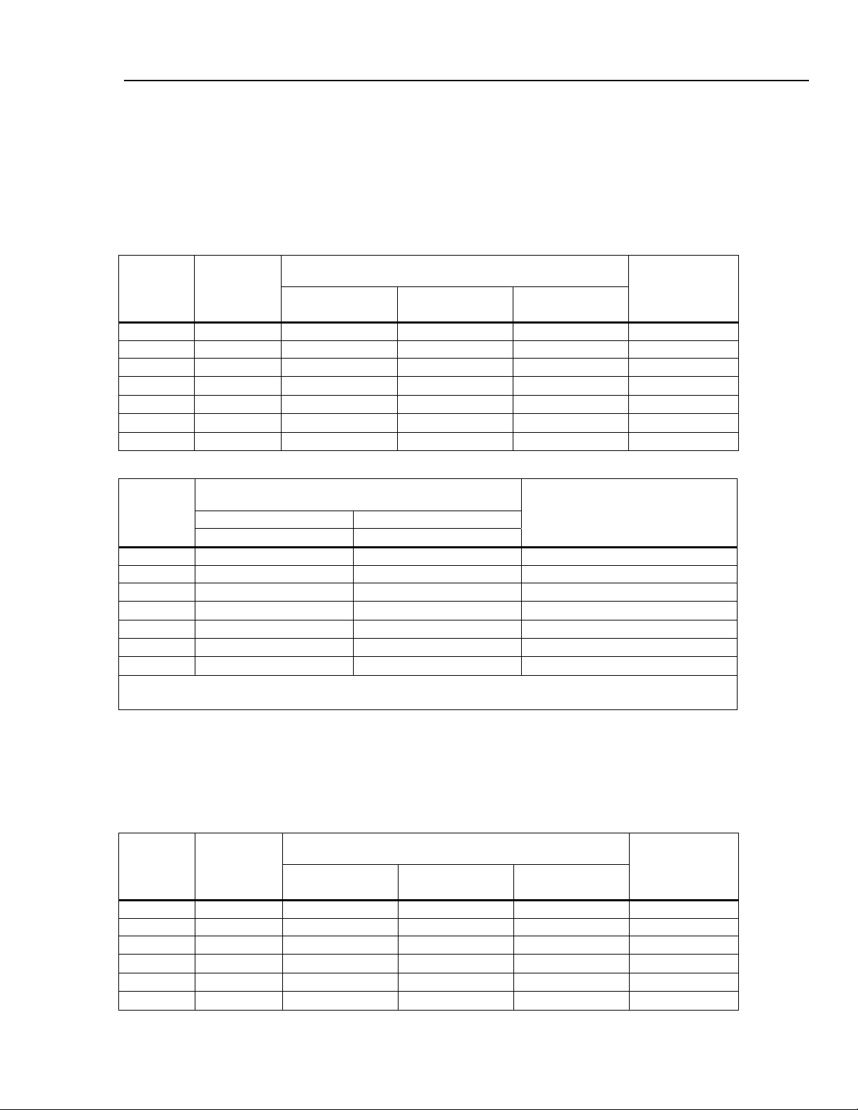
Electrical Specifications
Accuracy specifications are valid for 5-½ digit mode and after at least a half-hour warm-up
DC Voltage Specifications
Maximum Input ................................................. 1000 V on any range
Common Mode Rejection................................. 120 dB at 50 or 60 Hz ±0.1% (1 kΩ unbalance)
Normal Mode Rejection .................................... 80 dB at Slow Rate
A/D Nonlinearity................................................ 15 ppm of range
Input Bias Current ............................................ <30 pA at 25 °C
Settling Considerations ................................... Measurement settling times are affected by source impedance, cable
dielectric characteristics, and input signal changes
Input Characteristics
Range
200 mV 199.999 mV
2 V 1.99999 V
20 V 19.9999 V
200 V 199.999 V 1 mV 10 mV 10 mV
1000 V 1000.00 V 10 mV 100 mV 100 mV
Notes:
[1] At some dual display measurements, the input impedance of 200 mV and 2 V ranges may be changed to 10 MΩ.
Full-Scale
(5-1/2 Digits)
Slow Medium Fast
1 μV 10 μV 10 μV
10 μV 100 μV 100 μV
100 μV 1000 μV 1000 μV
Resolution
Input Impedance
>10 GΩ
>10 GΩ
10 MΩ±1 %
10 MΩ±1 %
10 MΩ±1 %
Accuracy
Accuracy
Range
200 mV 0.01 + 0.003 0.015 + 0.004 0.0015 + 0.0005
2 V 0.01 + 0.002 0.015 + 0.003
20 V 0.01 + 0.003 0.015 + 0.004
200 V 0.01 + 0.002 0.015 + 0.003
1000 V 0.01 + 0.002 0.015 + 0.003
Notes:
[1] Accuracy given as ± (% of reading + % of range)
90 days 1 year
23 °C ± 5 °C 23 °C ± 5°C
[1]
Temperature Coefficient/°C
Outside 18 – 28 °C
0.001 + 0.0005
0.0020 + 0.0005
0.0015 + 0.0005
0.0015 + 0.0005
[1]
[1]
1-9

8808A
Users Manual
AC Voltage Specifications
AC Voltage specifications are for ac sinewave signals >5 % of range. For inputs from 1 % to 5 % of range and <50 kHz,
add an additional error of 0.1 % of range, and for 50kHz to 100 kHz, add 0.13 % of range.
Maximum Input ................................................. 750 V rms or 1000 V peak or 8 x 10
Measurement Method ....................................... AC-coupled true-rms. Measures the ac component of input with up to
1000 V dc bias on any range.
AC Filter Bandwidth:
Slow ............................................................... 20 Hz – 100 kHz
Common Mode Rejection................................. 60 dB at 50 Hz or 60 Hz (1 kΩ unbalance)
Maximum Crest Factor .................................... 3:1 at Full Scale
Additional Crest Factor Errors (<100 Hz) ...... Crest Factor 1-2, 0.05 % of full scale
Crest Factor 2-3, 0.2 % of full scale
Input Characteristics
7
Volts-Hertz product
Range
200 mV 199.999 mV 1 uV 10 uV 10 uV
2 V 1.99999 V 10 uV 100 uV 100 uV
20 V 19.9999 V 100 uV 1000 uV 1000 uV
200 V 199.999 V 1 mV 10 mV 10 mV
750 V 750.00 V 10 mV 100 mV 100 mV
Full-Scale
(5-1/2 Digits)
Slow Medium Fast
Resolution
Input Impedance
1 MΩ ±2 % shunted by
<100 pf
Accuracy
Accuracy
Range Frequency
200 mV 20 Hz – 45Hz 0.8 + 0.05 0.9 + 0.05 0.01 + 0.005
45 Hz – 20 kHz 0.15 + 0.05 0.2 + 0.05 0.01 + 0.005
20 kHz – 50 kHz 0.3 + 0.05 0.35 + 0.05 0.01 + 0.005
50 kHz – 100 kHz 0.8 + 0.05 0.9 + 0.05 0.05 + 0.01
2 V 20 Hz – 45Hz 0.8 + 0.05 0.9 + 0.05 0.01 + 0.005
45 Hz – 20 kHz 0.15 + 0.05 0.2 + 0.05 0.01 + 0.005
20 kHz – 50 kHz 0.3 + 0.05 0.35 + 0.05 0.01 + 0.005
50 kHz – 100 kHz 0.8 + 0.05 0.9 + 0.05 0.05 + 0.01
20 V 20 Hz – 45 Hz 0.8 + 0.05 0.9 + 0.05 0.01 + 0.005
45 Hz – 20 kHz 0.15 + 0.05 0.2 + 0.05 0.01 + 0.005
20 kHz – 50 kHz 0.3 + 0.05 0.35 + 0.05 0.01 + 0.005
50 kHz – 100 kHz 0.8 + 0.05 0.9 + 0.05 0.05 + 0.01
200 V 20 Hz – 45Hz 0.8 + 0.05 0.9 + 0.05 0.01 + 0.005
45 Hz – 20 kHz 0.15 + 0.05 0.2 + 0.05 0.01 + 0.005
20 kHz – 50 kHz 0.3 + 0.05 0.35 + 0.05 0.01 + 0.005
50 kHz – 100 kHz 0.8 + 0.05 0.9 + 0.05 0.05 + 0.01
750 V 20 Hz – 45Hz 0.8 + 0.05 0.9 + 0.05 0.01 + 0.005
45 Hz – 20 kHz 0.15 + 0.05 0.2 + 0.05 0.01 + 0.005
20 kHz – 50 kHz 0.3 + 0.05 0.35 + 0.05 0.01 + 0.005
50 kHz – 100 kHz 0.8 + 0.05 0.9 + 0.05 0.05 + 0.01
Notes:
[1] Accuracy given as ± (% of reading + % of range)
90 days 1 year
23 °C ± 5 °C 23 °C ± 5 °C
[1]
Temperature
Coefficient/°C
Outside 18 – 28 °C
1-10
Introduction and Specifications
Electrical Specifications 1
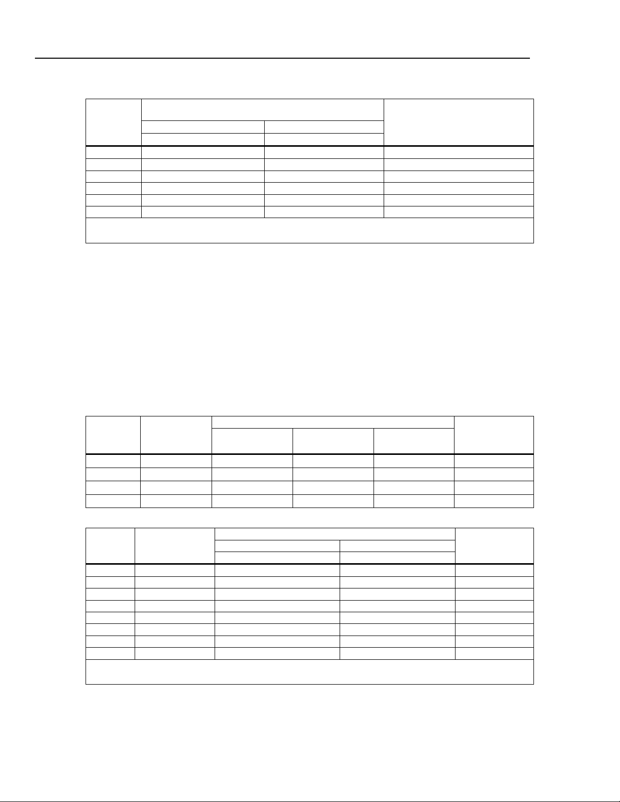
Resistance
Specifications are for 4-wire resistance function, or 2-wire resistance with REL. If REL is not used, add 0.2 Ω for 2-wire
resistance plus lead resistance.
Measurement Method ....................................... Current source referenced to LO input
Max Lead Resistance (4-wire ohms) ............... 10 % of range per lead for 200 Ω, 2 kΩ ranges. 1 kΩ per lead on all
Input Protection ................................................ 1000 V on all ranges
other ranges.
Input Characteristics
Range
200 Ω 199.999 Ω 0.001 Ω 0.01 Ω 0.01 Ω
2 kΩ 1.99999 kΩ 0.01 Ω 0.1 Ω 0.1 Ω
20 kΩ 19.9999 kΩ 0.1 Ω 1 Ω 1 Ω
200 kΩ 199.999 kΩ 1 Ω 10 Ω 10 Ω
2 MΩ 1.99999 MΩ 10 Ω 100 Ω 100 Ω
20 MΩ 19.9999 MΩ 100 Ω 1 kΩ 1 kΩ
100 MΩ 100.000 MΩ 1 kΩ 10 kΩ 10 kΩ
Full-Scale
(5-1/2 Digits)
Slow Medium Fast
Resolution
Accuracy
Accuracy
Range
200 Ω 0.02 + 0.004 0.03 + 0.004
2 kΩ 0.015 + 0.002 0.02 + 0.003
20 kΩ 0.015 + 0.002 0.02 + 0.003
200 kΩ 0.015 + 0.002 0.02 + 0.003
2 MΩ 0.03 + 0.003 0.04 + 0.004
20 MΩ 0.2 + 0.003 0.25 + 0.003
100 MΩ 1.5 + 0.004 1.75 + 0.004
Notes:
[1] Accuracy given as ± (% of reading + % of range)
90 days 1 year
23 °C ± 5 °C 23 °C ± 5 °C
[1]
Temperature Coefficient/°C
Current Source
0.8 mA
0.8 mA
0.08 mA
0.008 mA
0.9 μA
0.16 μA
0.16 μA || 10 MΩ
Outside 18 – 28 °C
0.003 + 0.0006
0.003 + 0.0005
0.003 + 0.0005
0.003 + 0.0005
0.004 + 0.0005
0.01 + 0.0005
0.2 + 0.0005
DC Current
Input Protection ............................................... Tool accessible 11 A / 1000 V and 440 mA / 1000 V fuses.
Shunt Resistance.............................................. 0.01 Ω for 2 A and 10 A ranges
Range
200 uA 199.999 µA
2 mA 1999.99 µA
20 mA 19.9999 mA
200 mA 199.999 mA
2 A 1.99999 A
10 A 10.0000 A
Full-Scale
(5-1/2 Digits)
Slow Medium Fast
0.001 μA 0.01 μA 0.01 μA
0.01 μA 0.1 μA 0.1 μA
0.1 μA 1 μA 1 μA
1 μA 10 μA 10 μA
10 μA 100 μA 100 μA
100 μA
1-11
1 Ω for 20 mA and 200 mA
Burden voltage < 1 mV for 200 uA and 2 mA range.
Input Characteristics
Resolution
1 mA 1 mA
Burden Voltage
<1 mV
<1 mV
<0.05 V
<0.5 V
<0.1 V
<0.5 V
8808A
Users Manual
Accuracy
Accuracy
Range
200 μA
2 mA 0.015 + 0.005 0.02 + 0.005 0.002 + 0.001
20 mA 0.03 + 0.02 0.04 + 0.02 0.005 + 0.001
200 mA 0.02 + 0.005 0.03 + 0.008 0.005 + 0.001
2 A 0.05 + 0.02 0.08 + 0.02 0.008 + 0.001
10 A 0.18 + 0.01 0.2 + 0.01 0.008 + 0.001
Notes:
[1] Accuracy given as ± (% of reading + % of range)
90 days 1 year
23 °C ± 5 °C 23 °C ± 5 °C
0.02 + 0.005 0.03 + 0.005 0.003 + 0.001
[1]
Temperature Coefficient/°C
Outside 18 – 28 °C
AC Current
The following ac current specifications are for sinusoidal signals with amplitudes greater than 5 % of range. For inputs
from 1 % to 5 % of range, add an additional error of 0.1 % of range.
Input Protection ................................................ Tool accessible 11 A / 1000 V and 440 mA / 1000 V fuses
Measurement Method ....................................... AC-coupled True RMS
Shunt Resistance.............................................. 0.01 Ω for 2 A and 10 A ranges
AC Filter Bandwidth:
Slow ................................................................ 20 Hz – 100 kHz
Maximum Crest Factor ..................................... 3:1 at Full Scale
Additional Crest Factor Errors (<100 Hz) ...... Crest Factor 1-2, 0.05 % of full scale
1 Ω for 20 mA and 200 mA
Crest Factor 2-3, 0.2 % of full scale
Input Characteristics
Range
20 mA 19.9999 mA
200 mA 199.999 mA
2 A 1.99999 A
10 A 10.0000 A
Full-Scale
(5-1/2 Digits)
Resolution
Slow Medium Fast
0.1 μA 1 μA 1 μA
1 μA 10 μA 10 μA
10 μA 100 μA 100 μA
100 μA
1 mA 1 mA
Burden Voltage
<0.05 V
<0.5 V
<0.1 V
<0.5 V
Accuracy
Accuracy
Range Frequency
20 mA 20 Hz - 45Hz 1 + 0.05 1.25 + 0.06 0.015 + 0.005
45 Hz - 2 kHz 0.25 + 0.05 0.3 + 0.06 0.015 + 0.005
200 mA 20 Hz - 45Hz 0.8 + 0.05 1 + 0. 06 0.015 + 0.005
45 Hz - 2 kHz 0.25 + 0.05 0.3 + 0.06 0.015 + 0.005
2 A 20 Hz - 45Hz 1 + 0.05 1.25 + 0.06 0.015 + 0.005
45 Hz - 2 kHz 0.25 + 0.05 0.3 + 0.06 0.015 + 0.005
10 A 20 Hz - 45Hz 1 + 0.1 1.25 + 0.12 0.015 + 0.005
45 Hz - 2 kHz 0.35 + 0.1 0.5 + 0.12 0.015 + 0.005
Notes:
[1] Accuracy given as ± (% of reading + % of range)
90 days 1 year
23 °C ± 5 °C 23 °C ± 5 °C
[1]
Temperature
Coefficient/°C
Outside 18 – 28 °C
1-12

Introduction and Specifications
Electrical Specifications 1
Frequency
Gate Time .......................................................... 131 ms
Measurement Method ....................................... AC-coupled input using the ac voltage measurement function.
Settling Considerations ................................... When measuring frequency after a dc offset voltage change, errors
Measurement Considerations ......................... To minimize measurement errors, shield inputs from external noise
Range Frequency
20 Hz – 2 kHz 0.01 + 0.002 0.01 + 0.003 0.002 + 0.001
100 mV to
[1,2]
750 V
Notes:
[1] Input > 100 mV
[2] Limited to 8* 10
2 kHz – 20 kHz 0.01 + 0.002 0.01 + 0.003 0.002 + 0.001
20 kHz – 200 kHz 0.01 + 0.002 0.01 + 0.003 0.002 + 0.001
200 kHz – 1 MHz 0.01 + 0.004 0.01 + 0.006 0.002 + 0.002
7
V Hz
may occur. For the most accurate measurement, wait up to 1 second
to allow input blocking RC time constant to settle.
when measuring low voltage, low frequency signals.
Accuracy
Accuracy
90 days 1 year
23 °C ± 5 °C 23 °C ± 5 °C
Temperature
Coefficient/°C
Outside 18 – 28 °C
Continuity
Continuity Threshold........................................ 20 Ω
Test Currents .................................................... 1 mA
Response Time ................................................ 100 samples/sec with audible tone
Rate…….…………………………………………… Fast
Maxiumum Reading………………………………199.99 Ω
Resolution……….….. ……………….……………0.01 Ω
Diode Test
Response Time ................................................. 100 samples/sec with audible tone
Rate………………………………………………….Fast
Maxiumum Reading………………………..….…1.9999 V
Resolution….………..….. ………………………..0.1 mV
1-13

8808A
Users Manual
1-14 2-1

Chapter 2
Preparing the Meter for Operation
Title Page
Introduction........................................................................................................ 2-3
Unpacking and Inspecting the Meter ................................................................. 2-3
Contacting Fluke................................................................................................ 2-3
Storing and Shipping the Meter ......................................................................... 2-3
Power Considerations ........................................................................................ 2-3
Selecting the Line Voltage ............................................................................ 2-4
Replacing the Fuses....................................................................................... 2-4
Line-Power Fuse ....................................................................................... 2-4
Current-Input Fuses................................................................................... 2-5
Connecting to Line Power ................................................................................. 2-7
Turning Power On ............................................................................................. 2-8
Adjusting the Bail .............................................................................................. 2-8
Installing the Meter into an Equipment Rack .................................................... 2-8
Cleaning the Meter............................................................................................. 2-9
Fluke 45 Emulation............................................................................................ 2-9
Illuminating All Display Segments.................................................................... 2-10

8808A
Users Manual
2-2

Preparing the Meter for Operation
Introduction 2
Introduction
This chapter explains how to prepare the Meter for operation by selecting the proper line
voltage, connecting the proper power cord for the selected line voltage, and turning the
Meter on. Also included is information on the proper storage, shipping, and cleaning of
the Meter.
Unpacking and Inspecting the Meter
Every care is taken in the choice of packing material to ensure that your Meter will reach
you in perfect condition. If the Meter has been subject to excessive handling in transit,
there may be visible external damage to the shipping carton. In the event of damage, keep
the shipping container and packing material for the carrier’s inspection.
Carefully unpack the Meter from its shipping container and inspect the contents for
damaged or missing items. If the Meter appears damaged or something is missing,
contact the carrier and Fluke immediately. Save the container and packing material in
case you have to return the Meter.
Contacting Fluke
To order accessories, receive operating assistance, or get the location of the nearest Fluke
distributor or Service Center, call:
USA: 1-888-99-FLUKE (1-888-993-5853)
Canada: 1-800-36-FLUKE (1-800-363-5853)
Europe: +31 402-675-200
Japan: +81-3-3434-0181
Singapore: +65-738-5655
Anywhere in the world: +1-425-446-5500
Or visit Fluke's Web site at www.fluke.com.
To register this product, visit register.fluke.com.
Storing and Shipping the Meter
To prepare the Meter for storage or shipping, place it inside a sealed bag, fit the bag into
the packing material inside the original shipping container, and then secure the package.
Use the original shipping container if possible, as it provides shock isolation for normal
handling operations. If the original shipping container is not available, use a box that is
17.5 x 15.5 x 8.0 inches, with cushioning material that fills the space between the Meter
and the sides of the box.
To store the Meter, place the box under cover in a location that complies with the storage
environment specifications described in the “General Specifications” section in Chapter
1.
Power Considerations
The Meter operates on varying power distribution standards found throughout the world
and must be set up to operate on the line voltage that will power it. The Meter is packed
ready for use with a line voltage determined at the time of ordering. If the selected line
voltage does not match the power that the Meter will be plugged into, the Meter’s linevoltage setting must be changed and replacement of the line fuse may be required.
2-3

8808A
Users Manual
Selecting the Line Voltage
The Meter operates on four different input line voltages. The selected line-voltage setting
is visible through the window in the line-fuse holder on the Meter’s rear panel.
1. Unplug the power cord.
2. Insert a small screwdriver blade into the narrow recess to the left of the fuse
holder and pry it to the right until the holder pops out. See Figure 2-1.
3. Remove the voltage-selector block from the fuse holder.
4. Rotate the selector block until the desired voltage rating faces outward.
5. Replace the selector block back into the fuse holder.
6. Install the fuse holder back into the Meter and reconnect the power cord.
Changing the line-voltage setting may require a different line-power fuse for proper
operation.
Replacing the Fuses
The Meter uses one fuse to protect the line-power input and two fuses to protect the
current-measurement inputs.
Line-Power Fuse
The Meter has a line-power fuse in series with the power supply. Table 2-1 indicates the
proper fuse for each of the four line-voltage selections. The line-power fuse is accessed
through the rear panel.
1. Unplug the power cord.
2. Insert a small screwdriver blade into the narrow recess to the left of the fuse
holder and pry it to the right until the holder pops out. See Figure 2-1.
3. Remove the fuse and replace it with a fuse of an appropriate rating for the
selected line-power voltage. See Table 2-1.
4. Replace the selector block back into the fuse holder.
To avoid electric shock or fire, do not use makeshift fuses or
short-circuit the fuse holder.
Line Voltage Selection Fuse Rating
XW Warning
Table 2-1. Line Voltage to Fuse Rating
100 / 120 0.125 A, 250 V (slow blow)
220 / 240 0.063 A, 250 V (slow blow)
2-4

Preparing the Meter for Operation
120
Figure 2-1. Replacing the Line Power Fuse
Power Considerations 2
eue20.eps
Current-Input Fuses
The 200 mA and 10 A inputs are protected by user-replaceable fuses.
• The 200 mA input is protected by a fuse (F2) rated at 440 mA, 1000 V (fast
blow), 10,000 A minimum breaking capacity.
• The 10 A input is protected by a fuse (F1) rated at 11 A, 1000 V (fast blow),
10,000 A minimum breaking capacity.
For protection against fire or arc flash, replace a blown fuse
with a fuse of an identical rating.
To test the current-input fuses:
1. Turn on the Meter and plug a test lead into the INPUT VZYR HI terminal.
2. Press O.
3. Press Vto set the range to 200 Ω. Only the 200 Ω, 2 kΩ, and 20 kΩ ranges can
be used to test the mA input fuse.
4. Insert the other end of the test lead into the mA terminal. If the fuse is good, the
Meter displays a reading of 0.000 Ω. If the fuse is blown, the Meter displays 0L
to indicate an overload.
5. Remove the test lead from the mA terminal and insert it into the 10 A terminal.
If the fuse is good, the Meter displays a reading of <1.000 Ω. If the fuse is blown,
the Meter displays 0L to indicate an overload.
XW Warning
XW Warning
To avoid electric shock, remove the power cord and any test
leads from the Meter before opening the current-input fuse
cover.
To replace the current-input fuses:
2-5

8808A
Users Manual
1. Remove power from the Meter by unplugging its power cord.
2. Turn the Meter upside down.
3. Remove the retaining screw on the fuse access door located on the bottom of the
Meter. See Figure 2-2.
4. Remove the protective cover from the fuse holders by slightly depressing the
back edge of the cover to unlatch it from the printed circuit board. Pull up on the
back edge of the cover and remove it from the fuse compartment.
5. Remove the defective fuse and replace it with a fuse of an appropriate rating. See
Table 2-1.
6. Replace the protective cover by pushing it over the fuses while aligning the
catches with the holes in the printed circuit board. Press the cover down until the
catches engage the printed circuit board.
7. Replace the fuse access door and install the retaining screw.
2-6
Fuses
Figure 2-2. Replacing the Current-Input Fuses
F2
F1
Bottom front
left corner
eue04.eps
 Loading...