

Fluke 88 Service Manual

88
Automotive Meter
Service Manual
For IEC 61010 CAT II Meters Only
PN 666856
November 1998 Rev.1, 11/99
© 1998, 1999 Fluke Corporation. All rights reserved. Printed in U.S.A.
All product names are trademarks of their respective companies.

LIMITED WARRANTY & LIMITATION OF LIABILITY
Fluke Corporation (Fluke) warrants this product to be free from defects in material and workmanship under normal use and service for the life
of the product. This warranty extends only to the original buyer or end-user customer of a Fluke authorized reseller, and does not apply to
fuses, batteries or to any product which, in Fluke’s opinion, has been misused, altered, neglected or damaged by accident or abnormal
conditions of operation or handling. Fluke warrants that software will operate on appropriate Fluke instruments substantially in accordance
with its functional specifications for 90 days and that it has been properly recorded on non-defective media. Fluke does not warrant that
software will be error free or operate without interruption.
Fluke authorized resellers shall extend this warranty on new and unused products to end-user customers only but have no authority to
extend a greater or different warranty on behalf of Fluke.
Fluke’s warranty obligation is limited, at Fluke’s option, to refund of the purchase price, or free of charge repair or replacement of a defective
product which is returned to an authorized Fluke Service Center within the warranty period.
To obtain warranty service, contact your nearest Fluke Service Center or send the product, with a description of the difficulty, postage and
insurance prepaid (FCA Destination), to the nearest Fluke Service Center. Fluke assumes no risk for damage in transit. Following warranty
repair, the product will be returned to Buyer, transportation prepaid (FCA Destination). If Fluke determines that the failure was caused by
misuse, alteration, accident or abnormal condition of operation or handling, Fluke will provide an estimate of repair costs and obtain
authorization before commencing the work. Following repair, the product will be returned to the Buyer transportation prepaid and the Buyer
will be billed for the repair and return transportation charges (FCA Shipping Point).
Warranty service is available outside the United States only if product was purchased through a Fluke Authorized Sales Outlet in the country
of use or the applicable Fluke international price was paid. Product transported from the United States for which the applicable Fluke
international price was not paid must be returned to the U.S. to receive warranty service, at the shipment expense and risk of Buyer. Fluke
reserves the right to invoice Buyer for importation costs of repair/replacement parts when product purchased in one country is submitted for
repair in another country.
THIS WARRANTY IS PURCHASER’S SOLE AND EXCLUSIVE REMEDY AND IS IN LIEU OF ALL OTHER WARRANTIES, EXPRESS OR
IMPLIED, INCLUDING BUT NOT LIM ITED TO ANY IMPLIED WARRANTY OF MERCHANTABILITY OR FITNESS FOR A PARTICULAR
PURPOSE. FLUKE SHALL NOT BE LIABLE FOR ANY SPECIAL, INDIRECT, INCIDENTAL OR CONSEQUENTIAL DAMAGES OR
LOSSES, INCLUDING LOSS OF DATA, WHETHER ARI SI NG FROM BREACH OF WARRANTY OR BASED ON CONTRACT, TORT,
RELIANCE OR ANY OTHER THEORY.
Since some countries or states do not allow limitation of the term of an implied warranty, or exclusion or limitation of incidental or
consequential damages, the limitations and exclusions of this warranty may not apply to every buyer. If any provision of this Warranty is held
invalid or unenforceable by a court of competent jurisdiction, such holding will not affect the validity or enforceability of any other provision of
this warranty.
Fluke Corporation Fluke Europe B.V.
P.O. Box 9090 P.O. Box 1186
Everett WA 5602 B.D. Eindhoven
98206-9090 The Netherlands

Safety Information
This meter complies with EN 61010-1:1993, ANSI/ISA S82.01-1994 and CAN/CSA
C22.2 No. 1010.1-92 Overvoltage Category II. Use the meter only as specified in the
Users Manual, otherwise the protection provided by the meter may be impaired.
A Warning identifies conditions and actions that pose hazards to the user; a Caution
identifies conditions and actions that might damage the meter. International electrical
symbols used on the meter are shown below.
W Warning
To avoid possible electric shock or personal inj ury:
• Do not use the meter if it is damaged. Bef ore use, inspect the
case for cracks or missing plastic. Pay particular att ent ion to the
insulation surrounding the connectors.
• Always turn off power to the circui t before cutting, unsoldering,
or breaking the circuit. Small amounts of current can be
dangerous.
• Inspect the test leads for damaged insulat ion or exposed metal.
Check test lead continuity. Replace damaged leads.
• To avoid damage or injury, never use the meter on unprotected
circuits that exceed 4800 volt-amps.
• Do not use the meter if it operates abnormally. Prot ect i on may be
impaired. When in doubt, have the meter serviced.
• Do not operate the meter around explosive gas, vapor or dust.
• Do not apply more than 300 V dc or ac rms (sine) between
terminals or between any terminal and earth ground.
• Before each use, verify the meter’s operation by measuring a
known voltage.
• When servicing the meter, use only specified replacement part s.
• Use caution when working above 30 V ac rms, 42 V ac peak, or 60
V dc. Such voltages pose a shock hazard.
• Keep your fingers behind the finger guards on the probe when
making measurements.
• Connect the common test lead before connecting the l i ve test
lead. Disconnect the live test lead first.
• Remove test leads from the meter before opening the case.
• Use only a single 9 V battery, properly installed in the meter case,
to power the meter.
• Follow all equipment safety procedures.
• Before measuring current, check the meter’s fuses (see “How to
Test the Fuse”).
Safety-1
• Never touch the probe to a voltage source when the test l eads are
plugged into the 10 A input jack.
• Always use clamp-on probes (dc current clamps) when
measuring current exceeding 10 A.
• DO NOT connect thermocouple to voltages exceeding 30 V.
• Always use a high voltage probe to measure voltage if peak
voltage might exceed 300 V.
• To avoid false readings, which could l ead t o possi ble electric
shock or personal injury, replace the meter’s battery as soon as
the low battery indicator (N) appears.
• To avoid fire hazard, only use a fuse identical in type, voltage
rating, and current rating to that speci f ied on the fuse rating label
located on the case bottom.
• Do not operate the meter if it is di sassembled. Always operate the
meter with the case top and bottom properly assembled.
Disassembly procedures and warnings are in the 78 Automotive
Service Manual. Service procedures are for qualified personnel
only.
Caution
To avoid possible damage to the meter or to equipment under
test:
• Disconnect the power to the circuit under t est and discharge all
high voltage capacitors before testing resi stance, continuity or
diodes.
• Use the proper function and range for your measurement
applications.
• When measuring current, turn off circuit power before connect i ng
the meter in the circuit. Remember to place the met er i n seri es
with the current.
Symbols
Symbol Meaning
Important information. See manual.
Ground
Fuse
Double insulation (Protection Class II)
Conforms to European Union directives
Safety-2

Table of Contents
Chapter Title Page
1 Introduction and Specifications........................................................ 1-1
1-1. Introduction.......................................................................................... 1-3
1-2. Organization of the Service Manual..................................................... 1-3
1-3. Conventions.......................................................................................... 1-4
1-4. Specifications....................................................................................... 1-4
2 Theory of Operation........................................................................... 2-1
2-1. Introduction.......................................................................................... 2-3
2-2. Functional Block Description............................................................... 2-3
2-3. Detailed Circuit Description ................................................................ 2-5
2-4. Input Overload Protection................................................................ 2-5
2-5. Rotary Switch................................................................................... 2-5
2-6. Input Signal Conditioning Circuits.................................................. 2-5
2-7. Volts............................................................................................. 2-6
2-8. Ohms............................................................................................ 2-6
2-9. Analog Section of Integrated Meter IC (U4) ................................... 2-6
2-10. Microcomputer Control ................................................................... 2-8
2-11. Peripherals to U4.............................................................................. 2-9
2-12. AC Buffer .................................................................................... 2-10
2-13. AC Converter............................................................................... 2-10
2-14. Active Filter................................................................................. 2-10
2-15. A/D Converter ............................................................................. 2-10
2-16. Beeper.......................................................................................... 2-10
2-17. Reference Voltage ....................................................................... 2-10
2-18. Power Supply............................................................................... 2-10
2-19. Display............................................................................................. 2-11
2-20. Rotary Knob Switch and Potentiometer .......................................... 2-11
3 Maintenance....................................................................................... 3-1
3-1. Introduction.......................................................................................... 3-3
3-2. Required Tools and Equipment............................................................ 3-3
3-3. Operator Maintenance.......................................................................... 3-4
3-4. Disassembing the Case..................................................................... 3-5
3-5. Removing and Reinstalling the Circuit Assembly........................... 3-5
i

88
Service Manual
3-6. Reassembling the Case..................................................................... 3-6
3-7. Replacing the Battery....................................................................... 3-7
3-8. Testing Fuses ................................................................................... 3-7
3-9. Replacing Fuses ............................................................................... 3-7
3-10. Cleaning........................................................................................... 3-8
3-11. Input Terminals............................................................................ 3-8
3-12. Function Encoding Potentiometer............................................... 3-8
3-13. Performance Test.................................................................................. 3-9
3-14. Testing the Display.......................................................................... 3-9
3-15. Testing Function Selection (Rotary Switch).................................... 3-10
3-16. Testing the AC Voltage Function.................................................... 3-10
3-17. Testing the Frequency Counter Function......................................... 3-11
3-18. Testing Frequency Sensitivity and Trigger Level............................ 3-12
3-19. Testing the DC Voltage Function.................................................... 3-12
3-20. Testing the DC mV Function........................................................... 3-13
3-21. Testing the Ohms Function.............................................................. 3-13
3-22. Testing the Diode Test Function...................................................... 3-13
3-23. Testing the mA Functions................................................................ 3-13
3-24. Testing the Amp Functions.............................................................. 3-14
3-25. Testing the Inductive Pickup............................................................ 3-14
3-26. Calibration............................................................................................ 3-18
3-27. Troubleshooting the Power Supply...................................................... 3-19
3-28. Common (Shunt) Regulator Troubleshooting.................................. 3-21
3-29. VDD (Series) Regulator Troubleshooting....................................... 3-23
3-30. Troubleshooting a Function Selection Malfunction............................. 3-23
3-31. Meter Does Not Turn Off (Problem 1)............................................ 3-24
3-32. Meter Enters Wrong Function (Problem 2)..................................... 3-24
4 List of Replaceable Parts .................................................................. 4-1
4-1. Introduction.......................................................................................... 4-3
4-2. How to Obtain Parts............................................................................. 4-3
4-3. Manual Status Information................................................................... 4-3
4-4. Newer Instruments................................................................................ 4-4
4-5. Service Centers..................................................................................... 4-4
4-6. Parts Lists............................................................................................. 4-4
5 Schematic Diagrams.......................................................................... 5-1
ii

List of Tables
Table Title Page
1-1. Summary of Accuracy Specifications.................................................................... 1-5
2-1. Typical Voltage Levels and Tolerance.................................................................. 2-11
3-1. Required Equipment.............................................................................................. 3-3
3-2. Function Selection Test......................................................................................... 3-10
3-3. AC Voltage Test.................................................................................................... 3-11
3-4. Frequency Test....................................................................................................... 3-11
3-5. Frequency Counter Sensitivity and Trigger Level Tests....................................... 3-12
3-6. DC Voltage Test.................................................................................................... 3-12
3-7. Ohms Test.............................................................................................................. 3-13
3-8. Milliamp Tests....................................................................................................... 3-14
3-9. Amp Tests.............................................................................................................. 3-14
3-10. Functional Description of Power Supply Components......................................... 3-20
3-11. Voltage Levels....................................................................................................... 3-20
4-1. Fluke 88 Final Assembly....................................................................................... 4-5
4-2. A1 Main PCA........................................................................................................ 4-7
iii

88
Service Manual
iv

List of Figures
Figure Title Page
2-1. Overall Functional Block Diagram........................................................................ 2-4
2-2. A/D Conversion..................................................................................................... 2-8
2-3. Function-Encoding Switch .................................................................................... 2-12
3-1. Battery and Fuse Replacement .............................................................................. 3-4
3-2. Assembly Details................................................................................................... 3-6
3-3. Display Test........................................................................................................... 3-9
3-4. Setup for Inductive Pickup Test ............................................................................ 3-16
3-5. Waveform for Inductive Pickup Test..................................................................... 3-17
3-6. Calibration Adjustment Points............................................................................... 3-19
3-7. Simplified Power Supply Schematic..................................................................... 3-22
4-1. Fluke 88 Final Assembly....................................................................................... 4-6
4-2. A1 Main PCA........................................................................................................ 4-9
5-1. A1 Main PCA........................................................................................................ 5-3
v
88
Service Manual
AUTO
RECORD MAX
RANGE
_
+
TRIG
20 2
4 6 3108 2 4 6 8 420
_
+
ZERO
MIN MAX RANGE HOLD
RPM
SMOOTH
mV
V
RPM
V
OFF
A
mA
10A
FUSED
88
Hz
400mA
FUSED
AUTOMOTIVE METER
MIN
AVG
AVG
H
M k
RPM
%DUTY
ms-PULSE
COM RPM
CAT
300V
m s %
T
AC
+
mA
A
II
DC
m V A
1
4000
mV
ALERT
TRIGGER
mA
A
V
POWER-UP OPTIONS
DISPLAY
+
Hz
2
PUSHBUTTONS
H
POWER-UP OPTIONS
PRESS 2 SEC. WHILE TURNING METER ON
LOW, OHMS/HIGH RESOLUTION
DISABLE AUTOMATIC POWER-OFF
ZERO
HI ACCURACY, 1 SEC. RESPONSE
MIN MAX
AUTORANGE VDC, VAC
RANGE
HI IMPENDANCE mV DC INPUT
HOLD
TURN OFF BEEPER
ALERT
TEST ROTARY SWITCH
RPM
ROTARY SWITCH
WARNING
TO AVOID ELECTRICAL SHOCK REMOVE
TEST LEADS BEFORE OPENING CASE
TO PREVENT DAMAGE OF INJURY
ELECTRICAL SHOCK
AND FUSE WARNINGS
FUSE RATINGS
BATTER Y TYPE
INSTALL QUICK ACTING FUSES WITH
AMP/VOLT RATINGS SHOWN.
F 44/100A 1000V
MIN INTERRUPT RATING 10 000A
F 11A 1000V
MIN INTERRUPT RATING 17 000A
9V NEDA 1604
PRODUCT
SERVICE
FLUKE CORPORATION
MADE IN USA
PAT. RE. 34,428 DES. 314,715 DES. 312,534 4,217,543
4,556,867 4,532,470 5,073,757 4,940,204 4,951,834
LR44340
SKID
RESISTANT
FEET
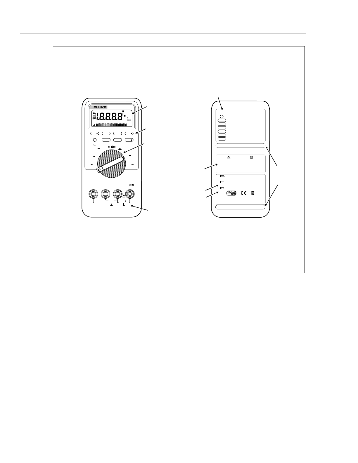
INPUT TERMINALS
FRONT
BACK
aad01f.eps
Frontispiece
vi

Chapter 1
Introduction and Specifications
Title Page
1-1. Introduction.......................................................................................... 1-3
1-2. Organization of the Service Manual..................................................... 1-3
1-3. Conventions.......................................................................................... 1-4
1-4. Specifications....................................................................................... 1-4
1-1

88
Service Manual
1-2

1-1. Introduction
This Service Manual provides information necessary to service the Fluke 88 Automotive
Meter. This information includes the following:
• Specifications
• Theory of operation
• Calibration routines
• Performance testing and troubleshooting procedures
• Replacement parts lists
• Schematic diagrams
A meter under warranty will be promptly repaired or replaced (at Fluke’s option) and
returned at no charge. See the registration card for warranty terms. If the warranty has
lapsed, the meter will be repaired and returned for a fixed fee. Contact the nearest
Service Center for information and prices. To contact Fluke, call one of the following
telephone numbers:
USA: 1-888-99-FLUKE (1-888-993-5853)
Canada: 1-800-36-FLUKE (1-800-363-5853)
Europe: +31 402-678-200
Japan: +81-3-3434-0181
Singapore: +65-738-5655
Anywhere in the world: +1-425-446-5500
Introduction and Specifications
Introduction
1
Or, visit Fluke’s Web site at www.fluke.com.
1-2. Organization of the Service Manual
The Service Manual has five chapters.
Chapter 1. Introduction and Specifications
Chapter 1 describes the Service Manual and explains conventions used to describe the
meter’s circuitry. A complete set of specifications appears at the end of this chapter.
Chapter 2. Theory of Operation
Chapter 2 treats the meter’s circuitry as functional blocks, with a description of each
block’s role in overall operation. A detailed circuit description is then given for each
block. These descriptions explore operation to the component level and support the
troubleshooting and repair procedures in Chapter 3.
Chapter 3. Maintenance
Chapter 3 provides complete maintenance information, detailed troubleshooting and
repair procedures to the component level, and performance tests. Troubleshooting and
repair procedures rely on the theory of operation in Chapter 2 and the schematic
diagrams in Chapter 5.
Chapter 4. List of Replaceable Parts
Chapter 4 provides parts lists for all assemblies and information on how to order parts.
1-3

88
Service Manual
1-3. Conventions
Chapter 5. Schematic Diagrams
Chapter 5 provides the schematic diagrams. A list of mnemonic definitions is included to
aid in identifying signal name abbreviations.
The following conventions are used in this manual:
• Instrument Reference
The term "Meter" is used when discussing the Fluke 88 Automotive Meter.
• Printed Circuit Assembly
The term "pca" is used to mean a printed circuit board and its attached parts.
• Signal Logic Polarity
Signal names followed by a minus sign (-) are active (or asserted) low. Signals not
so marked are active high.
• Circuit Nodes
Individual pins or connections on a component are specified by a dash (-) following
the component reference designator. For example, pin 19 of U30 would be U30-19.
• User Notation
Pushbuttons, positions on the rotary switch, input terminals, and the display are
genrally shown in the manual as they appear on the Meter. Mnemonics used in the
text that describe Meter circuitry are the same as those used on the schematic
diagrams in Chapter 5.
1-4. Specifications
Specifications for the Fluke 88 follow.
Accuracy is specified at 18°C to 28°C (64°F to 82°F) with relative humidity up to 90%,
for a period of one year after calibration. AC Conversions are ac-coupled, average
responding, and calibrated to the RMS value of a sine wave input.
The Fluke 88 has a Lo-Ohms/High Resolution power-up option. In the LoOhms/High Resolution mode, the resolution is ten times that in the
following specifications. To enter the Lo-Ohms/High Resolution mode,
press and hold down the SMOOTH button, while turning the rotary switch
to a function setting.
Table 1-1 provides a summary of the accuracy specifications for basic meter functions.
The complete Meter specifications follow Table 1-1. In the complete specifications,
accuracy is given as: ±([% of Reading] + [Number of Least Significant Digits])
Note
1-4
Introduction and Specifications
Specifications
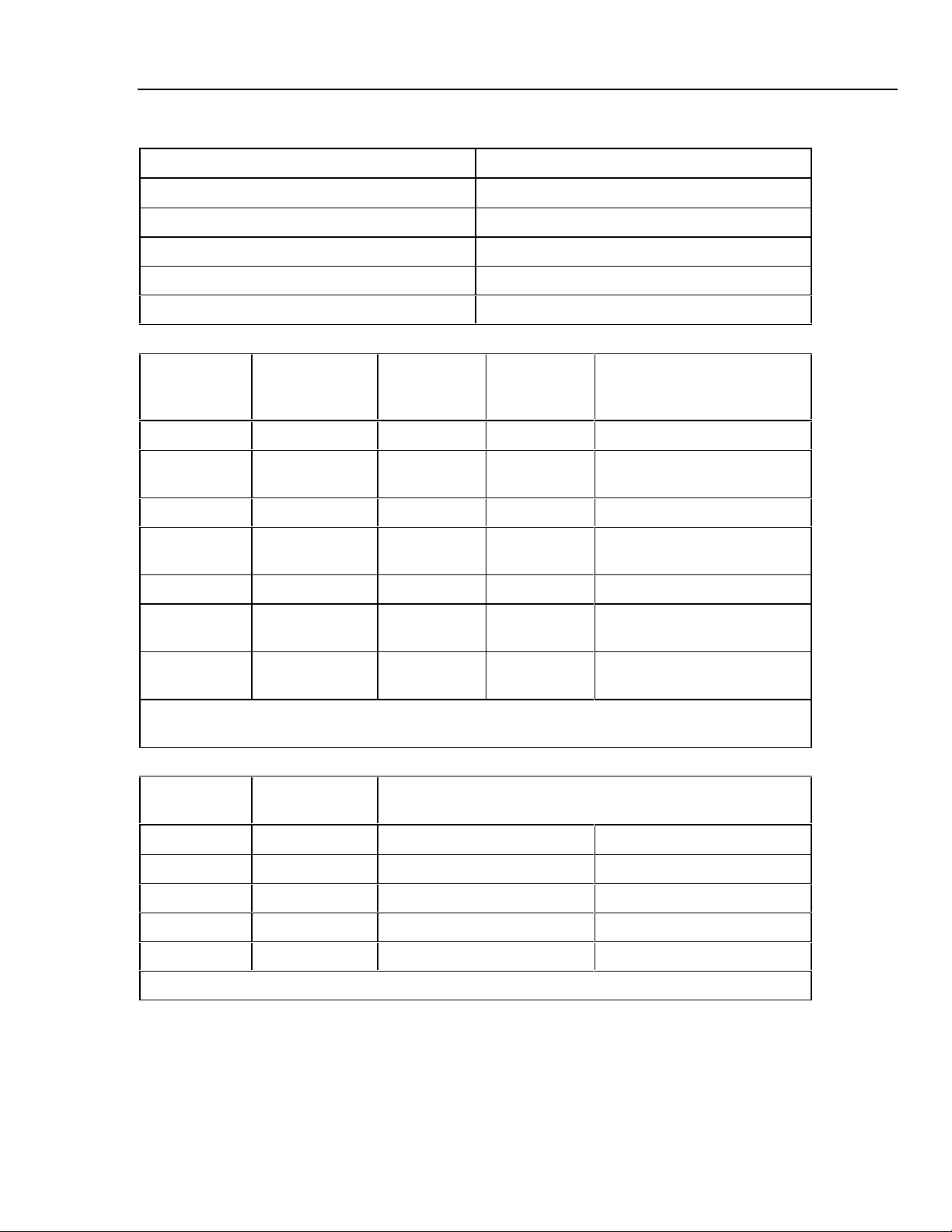
Table 1-1. Summary of Accuracy Specifications
Function Bassic Accuracy (± % of Reading)
Volts AC AV1.5%
Volts DC d V 0.15%
Resistance e 0.2%
Milliamps/Amps DC mA A d 0.8%
Frequency Hz 0.01%
Input Terminal Limits
1
Rotary
Switch
Function
~V V Ω G 0.01 mV 1000 V 300 V
F V
RPM
F mV V ΩG 0.01 mV 400.0 mV 300 V
R Ω
G V Ω G 0.0001V 3.000 V 300 V
mA
A~
mA
A F
* 10A continuous, 20A overload for 30 seconds maximum.
7
** 10
V-Hz maximum.
Volts AC
Range Resolution
Red Lead
RPM 0.0001 V 1000 V 300 V
V Ω G
A
mA
A
mA
Min Display
Reading
0.01Ω
(Lo-Ohms)
0.1 mA
0.001 mA
0.1 mA
0.001
45 Hz to 1 kHz 1 kHz to 5 kHz
Max Display
Reading
400.0 MΩ 300 V
20.00 A**
400.0 mA
20.00 A**
400.0 mA
Accuracy *
Maximum Input **
10 A/300 V*
400 mA/300 V
10A/300 V*
400 mA/300 V
400.0 mV 0.1 mV ±(1.5%+10) ±(1.9%+10)
4.000 V 0.001 V ±(1.5%+5) ±(1.9%+5)
40.00 V 0.01 V ±(1.5%+5) ±(1.9%+5)
300.0 V 0.1 V ±(1.5%+5) ±(1.9%+5)
300 V 1 V ±(2.5%+5) ±(2.5%+5)
*Below a reading of 200 counts, add 10 digits.
1-5
88
Service Manual
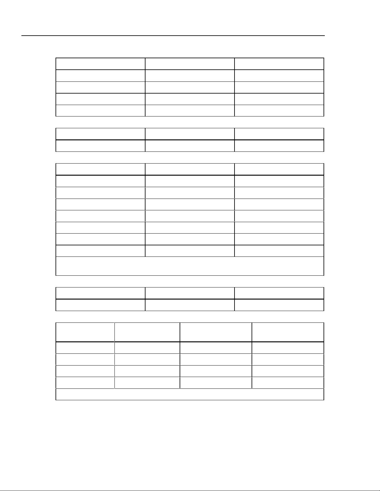
Volts DC
Range Resolution Accuracy
4.000 V 0.001 V ±(0.15%+2)
40.00 V 0.01 V ±(0.15%+2)
300.0 V 0.1 V ±(0.15%+2)
300 V 1 V ±(0.3%+2)
Millivolts DC
Range Resolution Accuracy
400.0 mV 0.1 mV ±(0.15%+2)
Resistance
Range Resolution Accuracy
400.0 Ω 0.1Ω* ±(0.2%+2)
4.000 kΩ 0.001 kΩ±(0.2%+2)
40.00 kΩ 0.01 kΩ±(0.2%+2)
400.0 kΩ 0.1 kΩ±(0.2%+2)
4.000 MΩ 0.001 MΩ±(0.2%+2)
40.00 MΩ 0.01 MΩ±(1%+3)
400.0 MΩ** 0.1 MΩ±(1%+20)
* In Lo-Ohms/High Resolution Mode, increases to 0.01Ω.
**This range will not be entered by Autorange. It must be selected manually.
Diode Test
Range Resolution Accuracy
3.000 V 0.001 V ±(2%+2)
mA/A DC
Range Resolution Accuracy Burden Voltage
40.00 mA 0.01 mA ±(0.8%+2) 2.3 mV/mA
400.0 mA 0.1 mA ±(0.8%+2) 2.3 mV/mA
4000 mA 1 mA ±(0.8%+2) 0.03 V/A
10.00 A* 0.01A ±(1.3%+2) 0.03 V/A
(typical)
1-6
* 10A continuous, 20A overload for 30 seconds maximum.

Introduction and Specifications
mA/A AC (45 Hz to 2 kHz)
Range Resolution Accuracy ** Burden Voltage
40.00 mA 0.01 mA ±(3%+10) 2.3 mV/mA
400.0 mA 0.1 mA ±(3%+5) 2.3 mV/mA
4000 mA 1 mA ±(1.5%+5) 0.03 V/A
10.0 A* 0.01 A ±(1.5%+5) 0.03 VA
* 10 A continuous, 20 A overload for 30 seconds maximum.
** Below reading of 200 counts, add 10 digits.
Frequency, RPM, Duty Cycle, and Pulse Width
(typical)
Specifications
1
Function Range Resolution Accuracy
Frequency** 199.99 0.01 Hz ±(0.01%+1) 1999.9 0.1
(0.5 Hz to 1999.9 0.1 Hz ±(0.01%+1) 5.00 0.01
200 kHz, 19.999 kHz 0.001 kHz ±(0.01%+1) 0.500 0.001
Pulse Width 199.99 kHz 0.01 kHz ±(0.01%+1) 0.0500 0.0001
>2 µs) >200 kHz 0.1 kHz Unspecified
RPM 1 30-9,000 1 RPM ± 2 RPM
RPM 2 60-12,000 1 RPM ± 2 RPM
% Duty Cycle*** 0.0-99.9%
(0.5 Hz to 200 kHz, Pulse Width > 2 µs)
Pulse Width *** 0.002-1999.9 ms
(4 Hz to 200 kHz, Pulse Width > 2 µs)
* Pulse Width range is determined by the frequency of the signal.
** Frequency measurements can be made on voltage or current inputs. The current inputs are always
dc-coupled.
*** For rise times < 1 µs. Duty Cycle accuracy: within ±(0.2% per kHz + 0.1%). Pulse Width accuracy:
±(00.002 ms + 3 digits).
Counter Sensitivity and Trigger Level
Pulse Width
Range (ms)*
Resolution
(ms)
Input Range* Minimum Sensitivity @ 0.5 Hz-200
kHz (RMS Sinewave)
400.0 mV dc 70 mV (to 400 Hz) 40 mV
400.0 mV ac 150 mV -
4.000 V 0.7 V 1.7 V
40.00 V 7 V 4 V
300.0 V 70 V (≤140 kHz) 40 V
Maximum input for specified accuracy = 10 × Range or 300 V.
Approximate Trigger Level (DC
Voltage Function)
1-7

88
Service Manual
Common and Normal Mode Rejection Ratio
Function Overload
Protection*
Input
Impedance
Common Mode Rejection
Ratio (1 kΩ unbalance)
Normal Mode
Rejection Ratio
(nominal)
F V 300 V rms 10 MΩ, <100 pF >120 dB at dc, 50 Hz, or 60 Hz >60 dB at 50 Hz or
60 Hz
F mV 300 V rms 10 MΩ, <100 pF >120 dB at dc, 50 Hz, or 60 Hz >60dB at 50 Hz or
60 Hz
B V 300 V rms 10 MΩ, <100 pF
>60 dB, dc to 60 Hz
(ac-coupled)
Open Circuit
Test
Voltage
Full Scale Voltage Short Circuit
To 4.0 mΩ 40 MΩ or
Current
nS
Ω 300 V rms <1.3 V dc <450 mV dc <1.3V dc <500 µA
Diode Test 300V rms <3.9 V dc 3.000 V dc 1.0 mA typical
7
* 10
V-Hz max.
MIN MAX Recording
Nominal Response Accuracy
100 ms to 80% Specified accuracy ± 12 digits for changes > 200 ms in duration
1 sec Same as specified accuracy for changes > 2 seconds in duration
1-8

Introduction and Specifications
Specifications
General
Maximum Voltage between any
Terminal and Earth Ground 300 V
Fuse Protection
mA 1 A 600 V FAST FUSE
A 15 A 600 V FAST FUSE
Display (LCD)
Digital Counts: 4,000
19,999 in High Resolution, 4½ -digit Mode only.
Update Rate: 1/sec in High Resolution, 4½ - digit mode only.
3/sec in RPM, Frequency, % Duty Cycle, and
Pulse Width
4/sec in all other functions and ranges.
Analog 2 x 32
Segments
Updates Rate: 40/sec
Frequency and RPM Counts: 19,999
Update Rate: 3/sec @ > 10 Hz
Backlight Backlight turns on for 68 seconds, then turns off automatically if not
turned off by user.
Meter Operating Temperature -20°C to 55°C (-4°F to 131°F)
Meter Storage Temperature -40°C to 60°C (-40°F to 140 °F)
Temperature Coefficient 0.05 x (Specified Accuracy)/ °C (<18°C or >28°C or 64°F or 82°F)
Relative Humidity 0% to 90% (0°C to 35°C; 32°F to 95°F)
0% to 70% (35°C to 55°C; 95°F to 131°F)
Altitude 2000 meters maximum
1
Inductive
Pickup
Input Magnetic Field from Spark Plug
Output Pulse to Trigger
Maximum RPM 12,000 (RPM 2)
Battery Type 9 V, NEDA 1604 or 6F22 or 006P
Battery Life 500 hrs typical with alkaline
Shock,
Vibration
Size (HxWxL)
Meter only 1.25 in x 3.41 in x 7.35 in (3.1 cm 8.6 cm x 18.6)
With Holster & Flex-
Stand
Weight
Meter only 12.5 oz (355 g)
With Holster & Flex-
Stand
Safety
Meter Complies with EN61010-1:1993, ANSI/ISA S82.01-1994,
Pickup Specified for spark-plug wire use only.
PER MIL-T-28800 for a Class 2 instrument.
2.06 in x 3.86 in x 7.93 in (5.2 cm x 9.8 cm x 20.1 cm)
22.0 oz (624 g)
CAN/CSA 22.2 No. 1010.1:1992 Overvoltage Category II. UL
License, TUV License, CSA License.
1-9

88
Service Manual
1-10

Chapter 2
Theory of Operation
Title Page
2-1. Introduction.......................................................................................... 2-3
2-2. Functional Block Description............................................................... 2-3
2-3. Detailed Circuit Description ................................................................ 2-5
2-4. Input Overload Protection................................................................ 2-5
2-5. Rotary Switch................................................................................... 2-5
2-6. Input Signal Conditioning Circuits.................................................. 2-5
2-7. Volts............................................................................................. 2-6
2-8. Ohms............................................................................................ 2-6
2-9. Analog Section of Integrated Meter IC (U4) ................................... 2-6
2-10. Microcomputer Control ................................................................... 2-8
2-11. Peripherals to U4.............................................................................. 2-9
2-12. AC Buffer .................................................................................... 2-10
2-13. AC Converter............................................................................... 2-10
2-14. Active Filter................................................................................. 2-10
2-15. A/D Converter ............................................................................. 2-10
2-16. Beeper.......................................................................................... 2-10
2-17. Reference Voltage ....................................................................... 2-10
2-18. Power Supply............................................................................... 2-10
2-19. Display............................................................................................. 2-11
2-20. Rotary Knob Switch and Potentiometer .......................................... 2-11
2-1
 Loading...