


October 2019
© 2019 Fluke Corporation. All rights reserved. Specifications are subject to change without notice.
All product names are trademarks of their respective companies.
87V MAX
Digital Multimeter
Users Manual

Lifetime Limited Warranty
Each Fluke 20, 70, 80, 170, 180 and 280 Series DMM will be free from defects in material and workmanship for its lifetime. As used herein,
“lifetime” is defined as seven years after Fluke discontinues manufacturing the product, but the warranty period shall be at least ten years from
the date of purchase. This warranty does not cover fuses, disposable batteries, damage from neglect, misuse, contamination, alteration,
accident or abnormal conditions of operation or handling, including failures caused by use outside of the product’s specifications, or normal
wear and tear of mechanical components. This warranty covers the original purchaser only and is not transferable.
For ten years from the date of purchase, this warranty also covers the LCD. Thereafter, for the lifetime of the DMM, Fluke will replace the LCD
for a fee based on then current component acquisition costs.
To establish original ownership and prove date of purchase, please complete and return the registration card accompanying the product, or
register your product on http://www.fluke.com. Fluke will, at its option, repair at no charge, replace or refund the purchase price of a
defective product purchased through a Fluke authorized sales outlet and at the applicable international price. Fluke reserves the right to
charge for importation costs of repair/replacement parts if the product purchased in one country is sent for repair elsewhere.
If the product is defective, contact your nearest Fluke authorized service center to obtain return authorization information, then send the
product to that service center, with a description of the difficulty, postage and insurance prepaid (FOB Destination). Fluke assumes no risk
for damage in transit. Fluke will pay return transportation for product repaired or replaced in-warranty. Before making any non-warranty
repair, Fluke will estimate cost and obtain authorization, then invoice you for repair and return transportation.
THIS WARRANTY IS YOUR ONLY REMEDY. NO OTHER WARRANTIES, SUCH AS FITNESS FOR A PARTICULAR PURPOSE, ARE
EXPRESSED OR IMPLIED. FLUKE SHALL NOT BE LIABLE FOR ANY SPECIAL, INDIRECT, INCIDENTAL OR CONSEQUENTIAL
DAMAGES OR LOSSES, INCLUDING LOSS OF DATA, ARISING FROM ANY CAUSE OR THEORY. AUTHORIZED RESELLERS ARE
NOT AUTHORIZED TO EXTEND ANY DIFFERENT WARRANTY ON FLUKE’S BEHALF. Since some states do not allow the exclusion or
limitation of an implied warranty or of incidental or consequential damages, this limitation of liability may not apply to you. If any provision of
this warranty is held invalid or unenforceable by a court or other decision-maker of competent jurisdiction, such holding will not affect the
validity or enforceability of any other provision.
Fluke Corporation
P.O. Box 9090
Everett, WA 98206-9090
U.S.A.
Fluke Europe B.V.
P.O. Box 1186
5602 BD Eindhoven
The Netherlands
ООО «Флюк СИАЙЭС»
125167, г. Москва, Ленинградский
проспект дом 37,
корпус 9, подъезд 4, 1 этаж
5/07

Table of Contents
Title Page
Introduction .................................................................................................................... 1
How to Contact Fluke ..................................................................................................... 1
Safety Information .......................................................................................................... 1
Features ......................................................................................................................... 2
Automatic Power-Off ................................................................................................. 9
Input Alert™ Feature ................................................................................................. 9
Power-Up Options ..................................................................................................... 9
How to Make Measurements .......................................................................................... 11
AC and DC Voltage Measurements ........................................................................... 11
Zero Input Behavior of True-rms Meter ..................................................................... 12
Low-Pass Filter .......................................................................................................... 12
Temperature Measurements ..................................................................................... 13
Continuity Tests ......................................................................................................... 14
Resistance Measurements ........................................................................................ 16
How to Use Conductance for High Resistance or Leakage Tests ............................. 18
i

87V MAX
Users Manual
Capacitance Measurements ..................................................................................... 19
Diode Tests ............................................................................................................... 20
AC or DC Current Measurements ............................................................................. 22
Frequency Measurements ........................................................................................ 25
Duty Cycle Measurements ........................................................................................ 27
How to Determine Pulse Width ................................................................................. 28
Bargraph ........................................................................................................................ 28
Zoom Mode (Power Up Option Only) ........................................................................ 29
Uses for the Zoom Mode .......................................................................................... 29
HiRes Mode ................................................................................................................... 29
MIN MAX Recording Mode ............................................................................................ 30
Smooth Feature (Power Up Option Only) ...................................................................... 30
AutoHOLD Mode ........................................................................................................... 32
Relative Mode ................................................................................................................ 32
Maintenance .................................................................................................................. 33
General Maintenance ................................................................................................ 33
Fuse Test .................................................................................................................. 33
How to Replace the Batteries.................................................................................... 34
How to Replace the Fuses ........................................................................................ 35
Service and Parts .......................................................................................................... 35
General Specifications ................................................................................................... 39
Detailed Specifications .................................................................................................. 41
AC Voltage ................................................................................................................ 41
DC Voltage, Conductance, and Resistance .............................................................. 42
Temperature ............................................................................................................. 43
AC Current ................................................................................................................ 43
DC Current ................................................................................................................ 44
Capacitance .............................................................................................................. 44
Diode ........................................................................................................................ 44
ii

Contents (continued)
Frequency ................................................................................................................. 45
Frequency Counter Sensitivity and Trigger Levels .................................................... 45
Duty Cycle (Vdc and mVdc) ...................................................................................... 46
Input Characteristics .................................................................................................. 46
MIN MAX Recording .................................................................................................. 47
iii

87V MAX
Users Manual
iv

Introduction
XW Warning
Read “Safety Information” before using the
Meter.
The 87V MAX (the Product or Meter) is a True-rms Digital
Multimeter. In addition, the 87V MAX measures
temperature using a type-K thermocouple.
How to Contact Fluke
To contact Fluke, call one of the following telephone
numbers:
• Technical Support USA: 1-800-44-FLUKE
(1-800-443-5853)
• Calibration/Repair USA: 1-888-99-FLUKE
(1-888-993-5853)
• Canada: 1-800-36-FLUKE (1-800-363-5853)
• Europe: +31 402-675-200
• Japan: +81-3-6714-3114
• Singapore: +65-6799-5566
• China: +86-400-921-0835
• Brazil: +55-11-3530-8901
• Anywhere in the world: +1-425-446-5500
Or, visit Fluke's website at www.fluke.com.
To register your product, visit http://register.fluke.com.
To view, print, or download the latest manual supplement,
visit http://us.fluke.com/usen/support/manuals.
Safety Information
General Safety Information is in the printed Safety
Information document that ships with the Product and at
www.fluke.com. More specific safety information is listed
where applicable.
1
87V MAX
Users Manual
Features
Tables 1 through 4 briefly describe the features of the Meter.
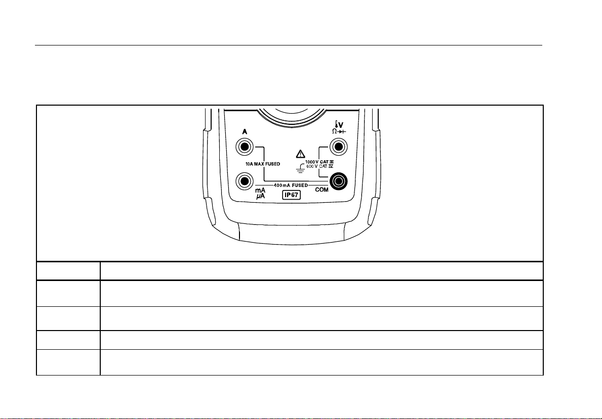
Table 1. Inputs
Terminal Description
A
COM
Input for 0 A to 10.00 A current (10 - 20 A overload for 30 seconds maximum), current frequency, and duty
cycle measurements.
Input for 0 μA to 400 mA current measurements (600 mA for 18 hrs) and current frequency and duty cycle.
Return terminal for all measurements.
Input for voltage, continuity, resistance, diode, capacitance, frequency, temperature, and duty cycle
measurements.
gaq112.emf
2

Digital Multimeter
Features
Table 2. Rotary Switch Positions
Switch Position Function
Any Position When the Meter is turned on, the Meter model number briefly appears on the display.
AC voltage measurement
(yellow) for low-pass filter ()
Press
DC voltage measurement
600 mV dc voltage range
Press for continuity test.
Press (yellow) for temperature ()
e Resistance measurement
Press (yellow) for capacitance measurement.
Diode test
AC current measurements from 0 mA to 10.00 A
(yellow) for dc current measurements, from 0 mA to 10.00 A.
Press
AC current measurements from 0 μA to 6000 μA
(yellow) for dc current measurements from 0 μA to 6000 μA.
Press
3

87V MAX
Users Manual
Table 3. Pushbuttons
Button
Switch
Position
(Yellow)
Any switch
position
Any switch
position
MIN MAX
recording
Frequency
counter
Selects capacitance
Switches between °C and °F.
Selects temperature
Selects ac low-pass filter function
Switches between dc and ac current
Switches between dc and ac current
Switches between the ranges available for the selected function. To return to autoranging, hold
the button down for 1 second.
AutoHOLD (formerly TouchHold) captures the present reading on the display. When a new,
stable reading is detected, the Meter beeps and displays the new reading.
Stops and starts recording without erasing recorded values.
Stops and starts the frequency counter.
Function
4

Digital Multimeter
Features
Table 3. Pushbuttons (cont.)
Button
Switch
Position
Continuity
MIN MAX
recording
Hz, Duty
Cycle
Any switch
position Turns the button backlight and display backlight on, makes them brighter, and turns them off.
Any switch
position
Turns the continuity beeper on and off
Switches between Peak (250 μs) and Normal (100 ms) response times.
Toggles the meter to trigger on positive or negative slope.
Hold down for one second to enter the HiRes digit mode. The “HiRes” icon appears on the
display. To return to the 3-1/2 digit mode, hold
Starts recording of minimum and maximum values. Steps the display through MAX, MIN, AVG
(average), and present readings. Cancels MIN MAX (hold for 1 second)
Function
down for one second. HiRes=19,999
5

87V MAX
Users Manual
Table 3. Pushbuttons (cont.)
Button Switch Position Function
(Relative
mode)
6
Any switch
position
Any switch
position except
diode test
Stores the present reading as a reference for subsequent readings. The display is
zeroed, and the stored reading is subtracted from all subsequent readings.
Press for frequency measurements.
Starts the frequency counter.
Press again to enter duty cycle mode.
Digital Multimeter
Features
Number Feature Indication
Negative readings, In relative mode,
this sign indicates that the present
input is less than the stored
reference.
High voltage present at the input.
Appears if the input voltage is 30 V
or greater (ac or dc), Also appears in
low-pass filter mode. Also appears in
cal, Hz, and duty cycle modes.
AutoHOLD is active.
Peak Min Max modes and the
response time is 250 μs.
Minimum-maximum recording mode.
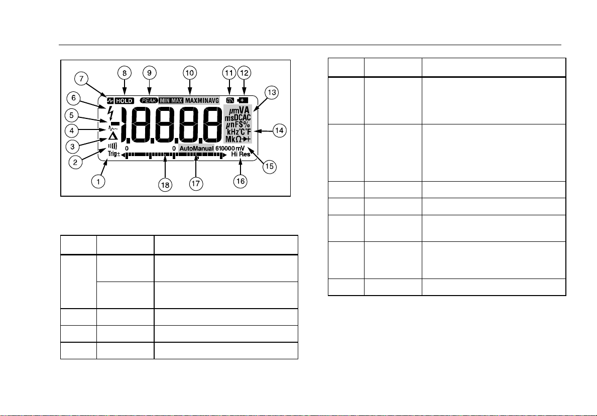
Figure 1. Display Features
Table 4. Display Features
Number Feature Indication
Polarity indicator for the analog
bargraph.
Trig±
Positive or negative slope indicator
for Hz/duty cycle triggering.
gaq101.emf
-
Display HOLD is active.
MAX MIN
AVG
See Low-pass Filter.
The continuity beeper is on.
Relative (REL) mode is active.
Smoothing is active.
7
87V MAX
Users Manual
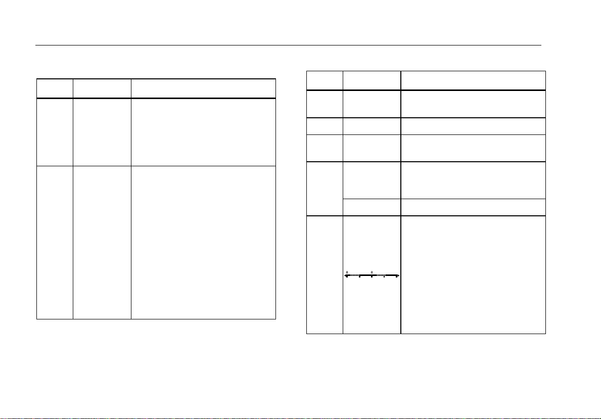
Table 4. Display Features (cont.)
Number Feature Indication
Low battery. XW Warning: To
prevent false readings, which
could lead to possible electric
shock or personal injury,
replace the battery as soon as
the battery indicator appears.
A, μA, mA amperes (amps), microamp, milliamp
V, mV volts, millivolts
μF, nF
microfarad, nanofarad
nS nanosiemens
%
Percent. Used for duty cycle
measurements.
Ω, MΩ, kΩ ohm, megohm, kilohm
Hz, kHz hertz, kilohertz
AC DC Alternating current, direct current
Diode test mode.
Number Feature Indication
°C, °F
Degrees Celsius, Degrees
Fahrenheit
610000 mV Displays selected range
HiRes
Auto
High resolution (Hi Res) mode.
HiRes=19,999
Autorange mode. Automatically
selects the range with the best
resolution
Manual Manual range mode
The number of segments is relative
to the full-scale value of the selected
range. In normal operation 0 (zero) is
on the left. The polarity indicator at
the left of the graph indicates the
polarity of the input. The graph does
not operate with the capacitance, or
frequency counter functions. For
more information, see Bargraph. The
bargraph also has a zoom function,
as described under "Zoom Mode".
8

Digital Multimeter
Features
Table 4. Display Features (cont.)
Number Feature Indication
--
Overload condition is detected.
Error Messages
Replace the battery immediately.
Invalid calibration data. Calibrate Meter.
Open thermocouple detected.
In the capacitance function, too much electrical
charge is present on the capacitor being tested.
Invalid EEPROM data. Have the Meter serviced.
Invalid model. Have the Meter serviced.
W Test lead alert. Displayed when the test leads are
in the
A or mA/μA terminal and the selected rotary
switch position does not correspond to the terminal
being used.
Automatic Power-Off
The Meter automatically turns off if you do not turn the
rotary switch or press a button for 30 minutes. If MIN
MAX Recording is enabled, the Meter will not power off.
Refer to Table 5 to disable automatic power-off.
Input Alert™ Feature
If a test lead is plugged into the mA/μA or A terminal, but
the rotary switch is not set to the correct current position,
the beeper warns you by making a chirping sound and
the display flashes “”, This warning is intended to
stop you from attempting to measure voltage, continuity,
resistance, capacitance, or diode values with the leads
are plugged into a current terminal.
W Caution
Placing the probes across (in parallel with) a
powered circuit when a lead is plugged into a
current terminal can damage the circuit you
are testing and blow the Meter’s fuse. This
can happen because the resistance through
the Meter’s current terminals is very low, so
the Meter acts like a short circuit.
Power-Up Options
Holding a button down while turning the Meter on
activates a power-up option. Table 5 describes power-up
options.
9

87V MAX
Users Manual
Table 5. Power-Up Options
Button Power-Up Option
(Yellow)
Disables automatic power-off feature (Meter normally powers off in 30 minutes).
The Meter reads “” until is released.
Enables the Meter’s calibration mode and prompts for a password.
The Meter reads “” and enters calibration mode. See 87V MAX Calibration Information.
Enables the Meter’s smoothing feature. The Meter reads “” until is released.
Turns on all LCD segments.
Disables the beeper for all functions. The Meter reads “” until is released.
(Relative mode)
10
Disables auto backlight off (backlight normally disables after 2 minutes). The Meter reads “” until is
released.
Enables zoom mode for the bargraph. The Meter reads “” until is released.
Enables the Meter’s high impedance mode when the mV dc function is used.
The Meter reads “” until is released.
Digital Multimeter
How to Make Measurements
How to Make Measurements
The following sections describe how to make
measurements with the Meter.
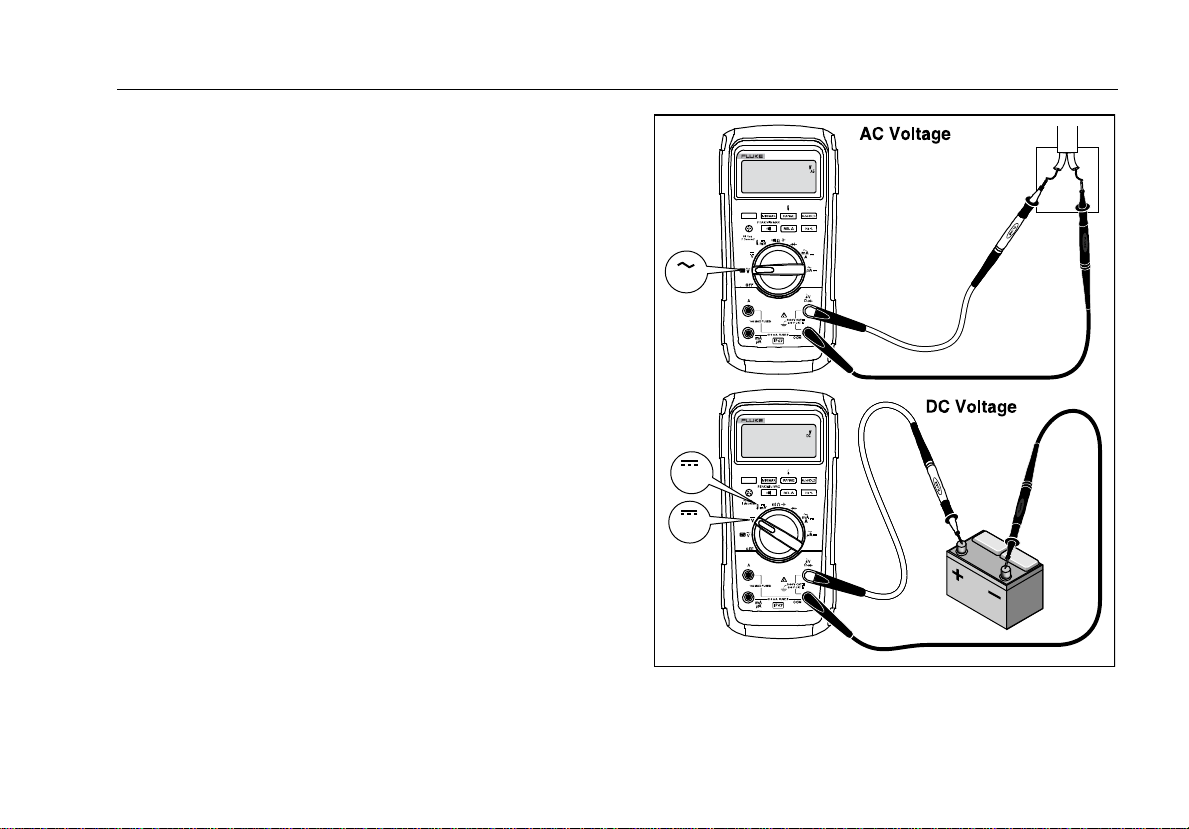
AC and DC Voltage Measurements
The Meter features true-rms readings, which are accurate
for distorted sine waves and other waveforms (with no dc
offset) such as square waves, triangle waves, and
staircase waves.
The Meter’s voltage ranges are 600.0 mV, 6.000 V,
60.00 V, 600.0 V, and 1000 V. The select the 600.0 mV
dc range, turn the rotary switch to mV.
Refer to Figure 2 to measure ac or dc voltage.
V
mV
V
Switch Box
Figure 2. AC and DC Voltage Measurements
gaq102.emf
11
 Loading...