

Page 1
Application Note
The elusive electrical intermittent
is one of the most difficult problems for anyone to troubleshoot.
The difficulty lies primarily in the
timing. Being able to look at the
symptoms while the problem is
present simplifies the troubleshooting process considerably.
However, the old adage “A
watched pot never boils” seems
to be applicable to electrical
intermittents as well. Being present, as well as being able to take
an electrical measurement while
the problem exists, are the two
biggest challenges in tracking
down an intermittent.
There are a number of test
tools that can help make the
intermittent troubleshooting
process a little easier. These tools
range from complex signal analyzers and storage oscilloscopes
to handheld digital multimeters
(DMM). Of course, you may not
have these tools available or the
location of the problem makes it
difficult to bring a large analyzer
to the problem site. A DMM may
be able to tell you a lot about an
intermittent without having to go
back to the shop and haul that
storage scope to the job site. This
article will describe how to use a
DMM as an intermittent troubleshooting tool.
DMM features for hunting
intermittents
Couple the basic measurement
features of a DMM (ac volts, dc
volts and resistance) with some
form of measurement recording
ability, and you have a tool for
detecting the symptoms of intermittents. Not too long ago, you
could buy a voltage or current
measuring tool that was built
around a mechanical strip chart
recorder. Just place the input on
a voltage, or clamp a current
transformer around a conductor
and the recorder would make
progressive marks on a strip of
paper fed under the marking
pen. The maximum length of the
recording was determined by the
amount of paper that could be
placed on a roll of paper. This
same strip chart recorder technique has been incorporated into
some of today’s DMMs.
Fluke’s 170 and 180 Series
DMMs have a feature called MIN
MAX AVG Recording Mode. Just
like the strip chart recorder, the
DMM takes a reading of the input
at regular intervals. But instead
Detecting intermittents
with a DMM
From the Fluke Digital Library @ www.fluke.com/library
of saving each reading, it compares the reading to two previously stored values to determine
if it is higher than previous highest reading or lower than the
previous lowest reading. If it is,
the new reading replaces the old
value stored in high or low reading register. After allowing the
recording process to continue for
a period of time, you can recall
these registers to the display and
see the highest and lowest reading taken during the recording
time. As an added bonus, these
DMMs will also compute and
store the average value of all
readings taken during a given
time period.
Page 2

2 Fluke Corporation Detecting intermittents with a DMM
To use the MIN MAX AVG
Recording mode:
1. Select the appropriate func-
tion for the desired measurement. (ac volts, dc volts,
resistance, ac current, dc current, and frequency)
2. Connect the test leads of the
DMM to the circuit to be
measured. Fluke’s SureGrip
test leads and probes offer a
multitude of circuit attachment methods. Make sure you
do this before activating the
MIN MAX AVG function, otherwise, the minimum reading
will be whatever the ambient
value is on the unconnected
test leads. This could throw
off your analysis of the
recorded data after the
recording time period expired.
3. Switch to manual range by
pressing the RANGE button. If
necessary, repeat pressing the
RANGE button until the correct range is indicated in the
DMM’s display. This step is
necessary because the DMM
will automatically switch to
manual range mode whenever the DMM is placed in the
MIN MAX AVG recording
mode. Once MIN MAX AVG is
activated, you cannot change
the range setting.
4. Press the
MIN MAX
to activate
the MIN MAX AVG recording
mode. In the Fluke 170 Series,
the display indicates the maximum reading and beeps each
time a new low or high value
is detected. In the Fluke 180
Series, the primary display
indicates the maximum reading while the secondary display indicates the present
measured value.
After insuring the DMM won’t
be disturbed and won’t present
a safety hazard to anyone, you
can leave the DMM unattended
while you focus on other tasks.
At anytime during the recording
period, you can review the
stored readings using the procedure in the next step, or pause
the recording mode without
deleting the stored readings by
pressing the HOLD button. To
continue recording, press the
HOLD button again.
5. View the stored readings by
pressing
MIN MAX
. Each press
of this button causes each of
the stored values (lowest,
highest and average readings) to be sequentially
recalled to the DMM’s display.
Elapse time stamp
The ability to determine when
the lowest and highest reading
was detected could also be useful information in determining
the cause of an intermittent
measurement. The Fluke 180
Series DMMs have the additional
ability of storing the amount of
time that has elapsed between
the start of recording and when
a new minimum or maximum or
average value was stored during
MIN MAX AVG recording. As a
result, each stored minimum,
maximum and average reading
has a “time stamp” associated
with it.
By separately documenting
the time of day you activated the
MIN MAX AVG recording mode,
you can easily calculate the
actual time of day a reading was
detected by the DMM. For example, assume you activated the
record mode at 3:07:00 p.m. and
the highest reading displayed
has an elapsed time of 47:05.
You simply add the elapsed time
to the start time to determine
what time of day the highest
reading was recorded. In this
example that would be 3:54:05
p.m. the same day.
Using the MIN MAX AVG
recording mode found in both
the 170 and 180 Series DMMs,
can be useful for some intermittent problems. But it assumes
the circuit point you are connected to will indicate the highest or lowest reading when the
problem appears. If the intermittent causes the measured value
to be between the highest and
lowest value, then the MIN MAX
AVG function will not be of
much help in determining the
source of the intermittent.
Advanced MIN MAX
Recording functions
The Fluke 189 True-rms Multimeter not only has the standalone MIN MAX AVG Recording
feature described above, but
also incorporates this feature
with another called AutoHOLD
and additional storage memory
to create the Event Logging
function.
AutoHOLD has the ability to
sense when a measured signal
becomes unstable and when it
re-stabilizes. Using the AutoHOLD feature to trigger the
starting and stopping of the
MIN MAX record function, you
are not limited to using the DMM
for problems that only result in
signals moving to a minimum or
maximum value.
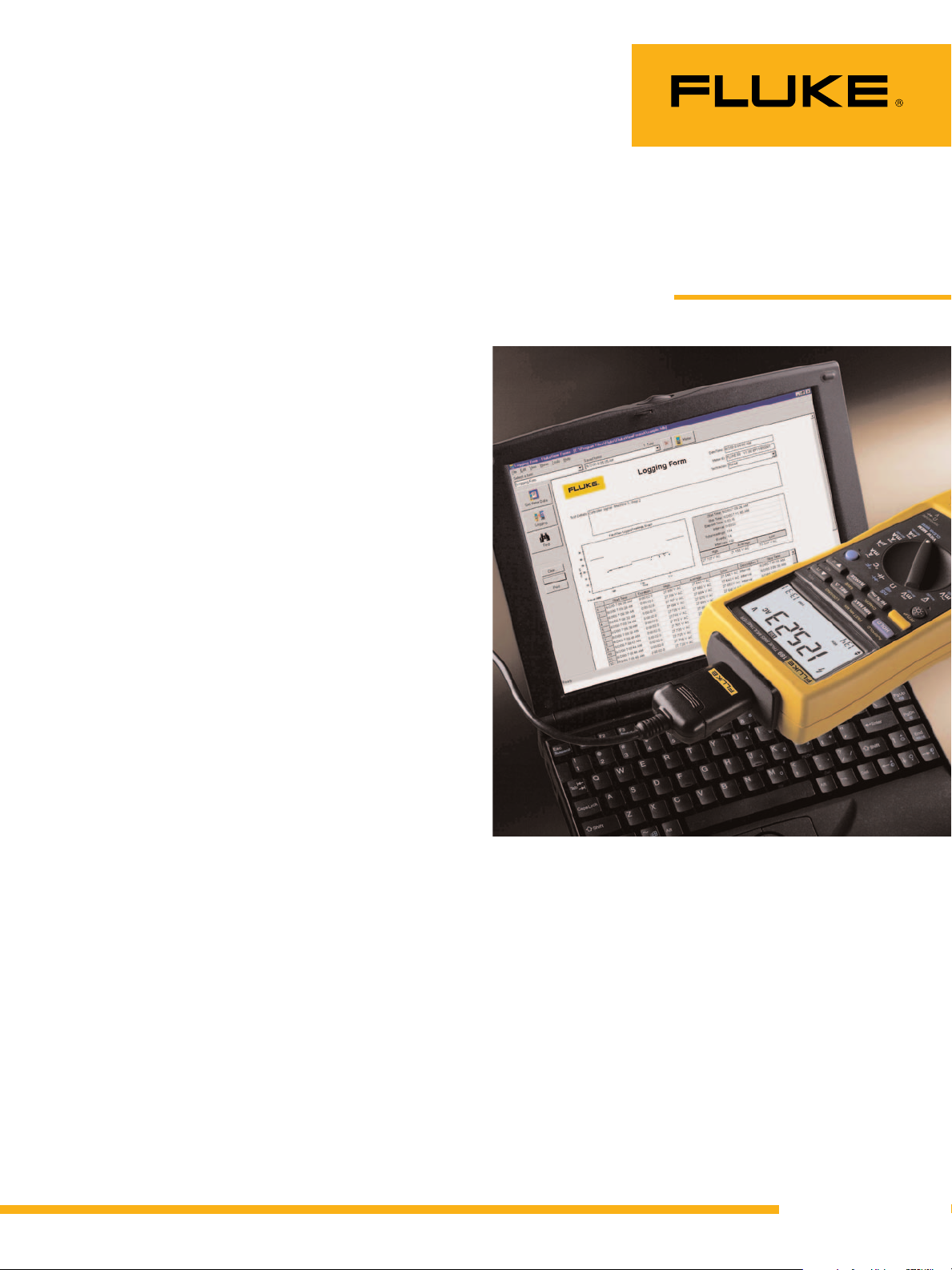
To use the Event Logging feature, you will need a Fluke 189
True-rms Multimeter, FlukeView
®
Forms Documenting Software
and a personal computer on
which to download and view
the recorded data. The DMM is
taken to the site where the
recording needs to be done and
set up to record for a period of
time, hopefully during which the
intermittent will occur. Only after
the recording is complete do you
need the software and PC.
As in the MIN MAX AVG
Recording steps above, setup the
meter by selecting the desired
measurement function and set
the range of the meter manually.
Connect the meter’s input to the
point to be measured and then
activate Event Logging.
Tip:
Do not remove the test leads from the circuit being measured until you have either
pressed the HOLD button to stop the
recording, or looked at and documented
all the stored values. Removing the leads
while recording will result in the DMM
processing the values present on the disconnected leads and affect the AVERAGE
value and possibly the lowest or highest
stored values taken during the time the
leads were connected to the circuit.
Page 3

3 Fluke Corporation Detecting intermittents with a DMM
Fluke Corporation
PO Box 9090, Everett, WA USA 98206
Fluke Europe B.V.
PO Box 1186, 5602 BD
Eindhoven, The Netherlands
For more information call:
In the U.S.A. (800) 443-5853 or
Fax (425) 446-5116
In Europe/M-East/Africa (31 40) 2 675 200 or
Fax (31 40) 2 675 222
In Canada (800) 36-FLUKE or
Fax (905) 890-6866
From other countries +1 (425) 446-5500 or
Fax +1 (425) 446-5116
Web access: http://www.fluke.com
©2003 Fluke Corporation. All rights reserved.
Printed in U.S.A. 6/2003 2098385 A-E NG-N Rev A
Fluke. Keeping your world
up and running.
As in the MIN MAX AVG
Recording mode, the DMM will
start storing the highest and
lowest values in memory. As
long as the measured signal
stays within a specified percent
of the selected range, the meter
will keep updating the same set
of MIN MAX values. However,
should the input signal value
change by more than a specific
percent of range, the DMM will
store the minimum and maximum values it has accumulated
so far, along with their respective time stamps and start accumulating another set of MIN
MAX values until the measured
signal stabilizes. Once stabilized,
the meter stores the minimum
and maximum readings for that
period and starts collecting a
new set of MIN MAX values for
the stable period. This process
continues for as long as the logging session is in progress or the
DMM runs out of memory.
Depending on how the meter is
setup, the meter has enough
memory to store up to three
days of MIN MAX pairs.
When the logging session is
terminated, the DMM can be
taken back to the shop and its
stored data transferred to a PC
through FlukeView Forms Documenting Software. Once in the
PC, each stable and unstable
event can be analyzed in detail.
Not only do you get to see the
minimum and maximum values
of each stable and unstable
period, but you also see the time
of day each period began and
ended. In addition, the average
value of each period is also
recorded.
The recorded data can be displayed on the PC either in table
form as in table 1, or in graphical form as in figure 1. Looking
at row three of table 1, you can
see the third event started at
9:53:30 a.m. on July 4, 2000.
The duration of the event was 1
minute and 20.6 seconds. The
highest value during the period
was 8.1 amps, the average of all
the values taken during the
event was 7.7 amps and the
lowest value was 7.5 amps. This
was a stable event and ended at
9:54:51 a.m. the same day. As
you can see from this example, a
lot of data can be captured during an intermittent period using
Event Logging.
Yes, locating intermittent
problems can be difficult, however, a DMM with the right features can help considerably in
tracking down these elusive
problems. Fluke’s wide range of
DMMs incorporate features that
are not only valuable for finding
intermittents, but a whole host
of other problems as well. Check
with your local Fluke distributor
or check Fluke’s web site at
www.fluke.com to find the test
tool that best fits your needs.
Table 1.
Figure 1.
E Start Time Duration High Average Low Description Stop Time
1 9:21:15 AM 32:14.7 0.0 A ac 0.0 A ac 0.0 A ac Stable 9:53:30 AM
2 9:53:30 AM 00:00.4 21.2 A ac 12.1 A ac 0.5 A ac Unstable 9:53:30 AM
3 9:53:30 AM 01:20.6 8.1 A ac 7.7 A ac 7.5 A ac Stable 9:54:51 AM
4 9:54:51 AM 02:06.5 7.5 A ac 7.4 A ac 7.3 A ac Stable 9:56:57 AM
5 9:56:57 AM 00:01.1 7.0 A ac 1.0 A ac 0.2 A ac Unstable 9:56:58 AM
6 9:56:58 AM 58:34.6 0.1 A ac 0.0 A ac 0.0 A ac Stable 11:55:33 AM
7 11:55:33 AM 00:00.3 20.8 A ac 11.7 A ac 0.3 A ac Unstable 11:55:33 AM
8 11:55:33 AM 01:23.3 8.4 A ac 8.0 A ac 7.8 A ac Stable 11:56:56 AM
9 11:56:56 AM 01:59.3 7.8 A ac 7.7 A ac 7.4 A ac Stable 11:58:56 AM
10 11:58:56 AM 00:00.7 6.6 A ac 1.3 A ac 0.2 A ac Unstable 11:58:56 AM
11 11:58:56 AM 00:04.5 0.2 A ac 0.1 A ac 0.0 A ac Stable 11:59:01 AM
 Loading...