

Page 1

Installation, Operation, and
Maintenance
July 2006
Manual No. 859A-1-1 Rev. 2
©2006 Fluke Corporation, All rights reserved. Printed in U.S.A.
All product names are trademarks of their respective companies.
Controller
Model 859A-1-72
Instruction Manual
Page 2

Fluke Biomedical
Radiation Management Services
6045 Cochran Road
Cleveland, Ohio 44139
440.498.2564
www.flukebiomedical.com/rms
Page 3

Table of Contents
Section 1: Introduction................................................................................................ 1-1
1.1 General Description ..................................................................................... 1-1
1.2 Specifications............................................................................................... 1-1
Section 2: Receiving Inspection................................................................................. 2-1
2.1 Receiving Inspection.................................................................................... 2-1
Section 3: Receiving Inspection Storage and Installation ....................................... 3-1
3.1 Storage ........................................................................................................ 3-1
3.2 Installation.................................................................................................... 3-2
Section 4: Operation.................................................................................................... 4-1
4.1 Operation..................................................................................................... 4-1
4.2 Controller Adjustments................................................................................. 4-2
Section 5: Maintenance ............................................................................................... 5-1
Section 6: Troubleshooting ........................................................................................ 6-1
Appendix A: Applicable Drawings..................................................................................A-1
Appendix B: Bills of Material ..........................................................................................B-1
List of Figures:
Figure Description Page
Figure 1-1 Model 859A-1-72 General View................................................................... 1-2
Figure 4-1 Input Pulse Specifications............................................................................ 4-2
i
Page 4

(Blank page)
Page 5
Introduction
1
Section 1
Introduction
1.1 General Description
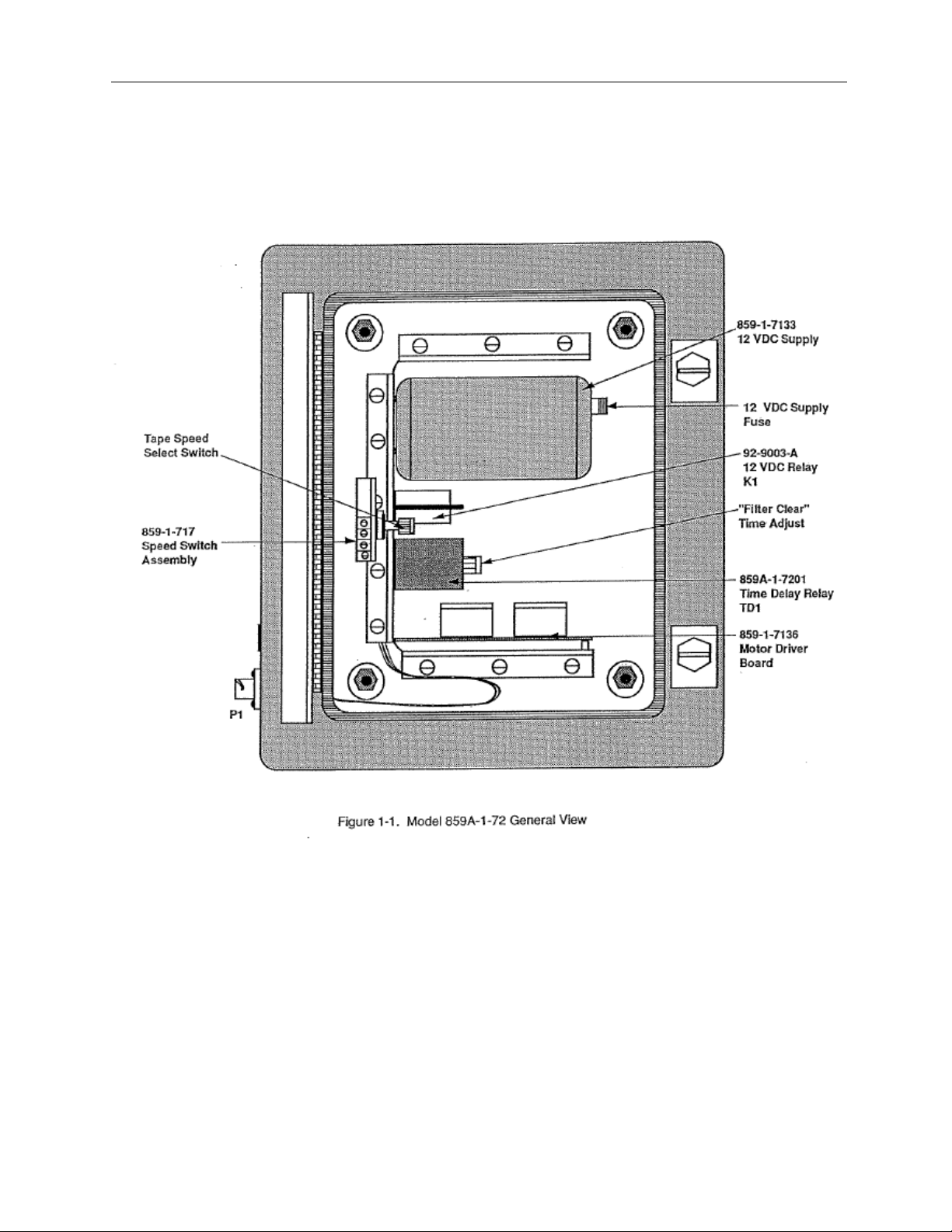
The Victoreen Model 859A-1-72 Controller is designed to be used in a process flow, radiation-monitoring
channel. Refer to figure 1-1 for a general view of the controller, or to Appendix A for all applicable
drawings.
The 859A-1-72 controller drives the stepping motor in an 859-1-50 Continuous Filter Air Sampler, which
determines the filter speed. Two methods are used by the controller to set filter speed. In the first
method, a rotary switch in the controller energizes the controller’s internal circuitry and sets the filter
speed at 0.5, 1, 2, or 10 inches per hour. The second method involves removing a jumper wire in the
controller, and allowing an external pulse to determine the filter speed.
The controller contains a power supply, motor driver circuit board, filter speed circuitry, and fast advance
circuitry.
The controller is built into a NEMA 12 enclosure and has four mounting brackets in a rectangul ar
configuration.
1.2 Specifications
General specifications are shown below.
Dimensions (H x W x D)
Weight
Enclosure
Operating Temp.
Relative Humidity
Power Requirements
16 in. x 12 in. x 6 in.
(40.64cm x 30.48cm x 15.24cm)
25 lb. (11.3kg)
NEMA 12
32°F to 130°F (0°C to 50°C)
0 to 95% non-condensing
110 to 130 VAC, 50/60 Hz
1-1
Page 6
Introduction
1
1-2
Page 7

Receiving Inspection
Section 2
Receiving Inspection
2.1 Receiving Inspection
Upon receipt of the unit:
1. Inspect the carton(s) and contents for damage. If damage is evident, file a claim with the carrier
and notify the Fluke Biomedical RMS Customer Service Department.
FLUKE BIOMEDICAL, RMS
6045 Cochran Rd.
Cleveland, OH 44139
Phone: (440) 498-2564
Fax: (440) 542-3682
www.flukebiomedical.com/rms
2. Remove the contents from the packing material.
3. Verify that all items listed on the packing list have been received and are in good condition.
NOTE
If any of the listed items are missing or damaged, notify the
Fluke Biomedical RMS Customer Service Department.
2
2-1
Page 8

(Blank Page)
2-2
Page 9

Storage and Installation
3
Section 3
Storage and Installation
3.1 Storage
Storage of the Victoreen instruments must comply with Level B storage requirements as outlined in ANSI
N45.2.2 (1972) Section 6.1.2(.2). The storage area shall comply with ANSI N45.2.2 (1972) Section 6.2
Storage Area, Paragraphs 6.2.1 through 6.2.5. Housekeeping shall conform to ANSI N45.2.3 (1972).
Level B components shall be stored within a fire resistant, tear resistant, weather tight enclosure, in a
well-ventilated building or equivalent.
Storage of Victoreen instruments must comply with the following:
1. Inspection and examination of items in storage must be in accordance with ANSI N45.2.2 (1972)
Section 6.4.1.
2. Requirements for proper storage must be documented and written procedures or instructions
must be established.
3. In the event of fire, post-fire evaluation must be in accordance with ANSI N45.2.2 (1972), Section
6.4.3.
4. Removal of items from storage must be in accordance with ANSI N45.2.2 (1972), Sections 6.5
and 6.6.
3.1 Installation
Ensure that all power is removed, prior to
connecting the controller.
Personnel performing the following procedure must
be familiar with the operation of the monitoring
system and the location of each piece of equipment
used in the system.
WARNING
CAUTION
CAUTION
3-1
Page 10

Storage and Installation
Failure to install the equipment in accordance with
the information presented in the assembly drawings
could result in damage to the equipment.
NOTE
Refer to the applicable drawings in Appendix A of
this manual or in the “Applicable Drawings”
appendix of the pertinent system level manual.
The Model 859A-1-72 Controller is mounted close to the 859-1-50 Continuous Filter Air Sampler, and all
required wiring is connected through one conne ctor. Electrical connections are made to a mating
connector, which runs to the P1 connector on the controller. For wiring information, refer to drawing
859A-1-3 and 859A-1-5 in Appendix A.
Ensure that all power is removed, prior to installing
the controller.
Prior to power up, ensure the controller cable is
properly connected.
WARNING
CAUTION
1. Apply power to the system.
3
3-2
Page 11

Operation
4
Section 4
Operation
4.1 Operation
Once installation is complete and the field wiring is connected, operation is fully automatic.
Controller operation is centered at an 859-1-7136 Motor Control. The motor control re ceives – 12 VDC
unregulated power and then outputs pulses for the necessary stepping sequence at the sampler. The
unregulated – 12 VDC is supplied by an 859-1-7133 Power Supply. Output pulses are supplied to the
stepping motor in one of two ways. The internal timing circuit can be used to generate pulses, or an
external source can be used to generate the required pulses.
Internal pulses are generated through a 555 integrated timing circuit in the motor control. A rotary switch
is provided to connect the appropriate resistor-capacitor circuit to the 555 timer, which sends pulses to
the stepping motor. The operator has the option of choosing filter speed. The choices are: 0.5, 1, 2, or
10 inches per hour. The operator can also choose the FILTER CLEAR function. FILTER CLEAR is
accomplished using a pair of relays, which override the selected resistor-capacitor circuit. This generates
a fast input pulse to the motor controller and will advance a predetermined length of filter paper from the
859-1-50 Continuous Filter Air Sampler. The relays are initiated through a push button switch inside the
859-1-50 Continuous Filter Air Sampler. The filter advance time is determined by the adjustable timer
relay.
External pulses can be used to drive the stepping motor. Remember that proper operation of the moving
filter depends on the shape and timing of the input pulse. To use externally generated pulses, remove
the jumper wire connecting S and V on the motor control. This will disable the 555 timer.
Externally generated pulses are received by the controller at connector P1, pin K. Pulses must meet the
requirements shown in figure 4-1. To move the filter one inch per hour, the controller requires an input
pulse at 14-second intervals. All other filter speeds are shown in the Controller Adjustments section of
section 4.
4-1
Page 12

Operation
4
4-2
Page 13

Operation
4
4.2 Controller Adjustments
The following procedures address filter speed adjustments for internally set filter speeds on the controller.
If an external pulse is used to set filter speed, the external equipment producing the pulse must be
checked independently of this procedure.
Refer to the applicable systems manual to perform system start-up.
Controller Timer Adjustments:
Use extreme care when performing adjustments with power applied
Refer to Appendix A, drawing 859-1-717 for resistor locations.
1. Turn the speed control switch to 10 in./hr. Adjust R14, (1 meg-ohm) to give one step every 1.5
seconds.
2. Turn the speed control switch to 2 in./hr. Adjust R13, (1 meg-ohm) to give one step every 7.5
seconds.
3. Turn the speed control switch to 1 in./hr. Adjust R12, (1 meg-ohm) to give one step every 15.0
seconds.
4. Turn the speed control switch to 0.5 in./hr. Adjust R11, (1 meg-ohm) to give one step every 30.0
seconds.
5. Push the FILTER CLEAR pushbutton on the 859-1-50 Continuous Filter Air Sampler and adjust
the timed relay to stop the fast advance after 5.5 seconds.
WARNING
NOTE
4-3
Page 14

(Blank Page)
4-4
Page 15

5.1 Maintenance
The Model 859-1-72 Controller requires no periodic maintenance.
Maintenance
5
Section 5
Maintenance
5-1
Page 16

(Blank Page)
5-2
Page 17

6.1 Troubleshooting
1. If a problem develops, verify the voltages at connection point inputs and outputs.
2. Refer to the applicable instruction manuals to troubleshoot other components of the system.
If a problem cannot be resolved by applying the troubleshooting and maintenance
Procedures provided in the applicable instruction manuals, please contact the Fluke
Biomedical Customer Service Department at (440) 498-2560 for assistance.
Disposal of Radioactive Material
6
Section 6
Troubleshooting
NOTE
6-1
Page 18

(Blank Page)
6-2
Page 19

Applicable Drawings
859-1-3 Wiring Diagram
859A-1-3 Wiring Diagram
859A-1-5 Moving Air Filter
859A-1-72 Controller, Main Assembly
859A-1-720 Controller, Frame Assembly
859-1-717 Speed Switch Assembly
Appendix
Applicable Drawings
Appendix A
A
A-1
Page 20

(Blank Page)
Page 21

Appendix
Bills of Material
B
Appendix B
Bills of Material
859A-1-5 Moving Air Monitor
859A-1-72 Controller, Main Assembly
859A-1-720 Controller, Frame Assembly
859-1-717 Speed Switch Assembly
B-1
Page 22

Fluke Biomedical
Radiation Management Services
6045 Cochran Road
Cleveland, Ohio 44139
440.498.2564
www.flukebiomedical.com/rms
 Loading...