

Page 1

80K-15
Electronic Air Cleaner Probe
Instruction Sheet
Introduction
The 80K-15 Electronic Air Cleaner Probe (hereafter referred
to as “the probe”) is a low energy probe that extends the
voltage measuring capability of an ac/dc voltmeter or
multimeter.
Properly connected, the probe is rated to 15 kV Overvoltage
Category I. The use of the probe is restricted to low energy
applications, which are energy limited circuits like
electrostatic air cleaners.
measure high voltages on power distribution systems.
The probe is a precision 1000 : 1 voltage divider formed by
two matched resistors. The unusually high input impedance
offered by these resistors minimizes circuit loading and
thereby optimizes measurement accuracy.
Do not use this probe to
®
W
Read First: Safety Information
WWarning
To avoid possible personal injury or electrical shock:
• Use the probe within its voltage ratings and in dry
conditions (no condensation is present).
• Be familiar with and exercise all possible high
voltage safety practices.
• DO NOT use this probe to measure high voltage on
power distribution systems.
• Always hold the probe by its gray handle. Never
allow the probe tip or the yellow part of the probe
to make body contact.
• Before making a measurement, make sure that the
side of the probe plug with the GND tab is plugged
into the low (COM) terminal of the meter.
• Attach the grounding lead to earth ground.
• Use a meter with an impedance of 10 MΩ ( ± 1% ).
Using a meter with an input impedance less than
10 MΩ reduces the accuracy of the reading by
causing it to be lower than the voltage present.
• DO NOT use the probe with a Fluke multimeter that
is in the kChek or Automatic Selection mode (i.e.
Fluke 16, Fluke 12B etc.). The input impedance in
these modes is very low.
• Make sure the probe tip is firmly attached to the
body of the probe.
• DO NOT use the probe around explosive gas,
vapor, or dust.
• DO NOT use the probe if it operates abnormally.
Protection may be impaired. When in doubt have
the probe serviced.
PN 690385 May 1998
©1998 Fluke Corporation. All rights reserved. Printed in U.S.A.
Page 2
80K-15
Electronic Air Cleaner Probe
Symbols
Double insulated.
T
Refer to explanation in this instruction sheet.
W
Lethal voltages may be present.
X
Complies with relevant Canadian Standards
Association directives.
Earth ground
Using the Probe
1
4. Connect the alligator clip of the probe’s grounding lead
to earth ground.
5. Touch the probe tip to the circuit being measured and
read the measurement on the meter display. If
necessary, apply a correction factor to the reading.
(See “Note” in the “Specifications,” below.
Table 1. 80K-15 Circuit Loading and Input/Output
Characteristics
Input Voltage Loading Current Output Voltage
10 V 10 nA 10 mV
100 V 100 nA 100 mV
TRUE RMS MULTIMETER
87
III
DC
H
MIN MAX RANGE HOLD
HzREL
PEAK MIN MAX
41/2 DIGITS
1 Second
mV
mA
V
A
µA
2
V
OFF
A
mAµA
10A MAX
FUSED
V
COM
!
400mA MAX
CAT II
FUSED
1000V MAX
!
3
1 kV 1 µA1 V
10 kV 10 µA 10 V
15 kV 15 µA 15 V
Specifications
The 80K-15 Electronic Air Cleaner Probe achieves its rated
accuracy when it is used with a voltmeter or multimeter (ac
or dc) with an input impedance of 10 MΩ ± 1%.
The accuracy of the probe does not include the accuracy of
4
the meter. To get the accuracy of the system, the accuracy
of the meter must be added to the accuracy of the probe.
5
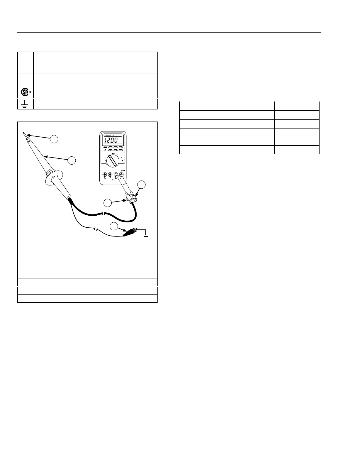
EAOO1F.EPD
A Probe tip
B Probe body
C Plug
D GND tab
E Grounding lead clip
F Multimeter or voltmeter
Figure 1. 80K-15 Electronic Air Cleaner Probe
The 80K-15 (Figure 1) is designed to work with a meter that
has an input impedance of 10 MΩ ( ± 1% ). A meter with an
input impedance less than 10 MΩ can produce readings
lower than the voltage present. This can pose a serious
hazard when a dangerous voltage is present.
The 80K-15 represents a 1000 MΩ load to the circuit being
measured, or 1 µA per 1 kV. Table 1 shows the circuit
loading and input/output characteristics of the probe over its
measurement range.
Taking care to follow the safety practices under “WRead
First: Safety Information,” use the probe as follows:
1. Turn on a compatible voltmeter or multimeter and
select the voltage measurement function.
2. Select an appropriate voltage range (i.e., 1 volt reading
per 1000 volt input. See Table 1).
3. Connect the probe’s output leads to the voltmeter or
multimeter input terminals.
Note
The input impedance of the Autoranging mode on
Fluke handheld digital multimeters varies by range.
The input impedance in almost all ranges of Fluke
Ω
multimeters is ~10 M
. The exceptions are: the 3 V
range on the Fluke Models 21, 23, 25, 27, 70, 73,
75, 7; and the 4 V range on the Models 10, 11, 12,
16, 79, 83, 85, 86, 87, 88. In the ranges on these
Ω
multimeters, the impedance is 11.11 M
.
To improve the measurement accuracy of the probe
when using these ranges on the models indicated,
apply a correction factor of 0.99 i.e., multiply the
display reading by 0.99.
Voltage Range:
1 kV to 15 kV dc or peak ac,
10 kV rms ac
Maximum Current:
Input Resistance:
Division Ratio:
Accuracy DC:
Accuracy AC:
Safety:
20 µA
1000 MΩ
1000 : 1 (1000 x attenuation)
± 2 % in 10
o
C to 45 o C
± 5 % @ 60 Hz, in 20 o C to 30 o C
Complies with IEC 1010-2-31:1993,
Type B, 15 kV dc or peak ac, 10 kV
rms ac, Overvoltage Category I
(voltages derived from limited energy
transformer).
Altitude:
2000 meters
Page 3

Performance Test
Verify the accuracy of the probe by measuring a 15 kV dc
(± 0.25 %) voltage source. When used with a compatible
dc voltmeter, the probe should measure the source with
± 1% accuracy. No calibration adjustments are needed.
Warranty
LIMITED WARRANTY & LIMITATION OF LIABILITY
This Fluke product will be free from defects in material
and workmanship for one year from the date of
purchase. This warranty does not cover fuses,
disposable batteries or damage from accident, neglect,
misuse or abnormal conditions of operation or handling.
Resellers are not authorized to extend any other
warranty on Fluke’s behalf. To obtain service during the
warranty period, send your defective tester to the
nearest Fluke Authorized Service Center with a
description of the problem.
THIS WARRANTY IS YOUR ONLY REMEDY. NO
OTHER WARRANTIES, SUCH AS FITNESS FOR A
PARTICULAR PURPOSE, ARE EXPRESSED OR
IMPLIED. FLUKE IS NOT LIABLE FOR ANY SPECIAL,
INDIRECT, INCIDENTAL OR CONSEQUENTIAL
DAMAGES OR LOSSES, ARISING FROM ANY CAUSE
OR THEORY. Since some states or countries do not
allow the exclusion or limitation of an implied warranty or
of incidental or consequential damages, this limitation of
liability may not apply to you.
Fluke Corporation Fluke Europe B.V.
P.O. Box 9090 P.O. Box 1186
Everett, WA. 5602 B.D. Eindhoven
98206-9090 The Netherlands
10/96
Contacting Fluke
For application or operation assistance, or information
on Fluke products, call:
USA: 1-888-99-FLUKE (1-888-993-5853)
Canada: 1-800-36-FLUKE (1-800-363-5853)
Europe: +31 402-678-200
Japan: +81-3-3434-0181
Singapore: +65-738-5655
Anywhere in the world: +1-425-446-5500
Or, visit Fluke’s Web site at www.fluke.com.
 Loading...