

Page 1

English
Getting Started
May 2001 Rev.2, 12/03
©
2001-2003 Fluke Corporation, All rights reserved. Printed in U.S.A.
All product names are trademarks of their respective companies.
®
80 Series III
Multimeters
Page 2

Lifetime Limited Warranty
Each Fluke 20, 70, 80, 170 and 180 Series DMM will be free from defects in material and workmanship for its lifet ime. As us ed herein, “lif et ime” is
defined as seven years after Fluke discont inues manufac t uring t he produc t , but t he warranty period s hall be at least ten years from the date of
purchase. This warranty does not cover fuses , dis pos able bat t eries , damage from neglect , mis us e, c ont amination, alt erat ion, accident or abnormal
conditions of operation or handling, including failures caus ed by us e out s ide of t he produc t ’s s pec ifications, or normal wear and tear of mechanical
components. This warranty covers the original purchaser only and is not t rans f erable.
For ten years from the date of purchase, this warranty als o c ov ers t he LCD. Thereafter, f or t he lif et ime of t he DMM, Fluke will replace the LCD for a
fee based on then current component acquisition cos t s .
To establish original ownership and prove date of purchase, please complete and ret urn t he regis t rat ion c ard ac c ompanying t he p roduc t , or regis t er
your product on http://www.fluke.com. Fluke will, at its option, repair at no charge, replace or refund the purchase price of a defective product
purchased through a Fluke authorized sales outlet and at t he applic able int ernat ional pric e. Fluke res erv es t he right t o c harge f or importat ion c os t s
of repair/replacement parts if the product purchas ed in one c ount ry is s ent f or repair els ewhere.
If the product is defective, contact your nearest Fluke authorized servic e c ent er t o obt ain ret urn aut horiz at ion inf ormation, t hen s end t he produc t t o
that service center, with a descript ion of t he dif f ic ult y , pos t age and ins uranc e prepaid (FOB Destinat ion). Fluke as s umes no risk f or damage in
transit. Fluke will pay return transportation for produc t repaired or replac ed in-warranty . Bef ore making any non-warranty repair, Fluke will est i mate
cost and obtain authorization, then invoice y ou f or repair and ret urn t r ans port at ion.
THIS WARRANTY IS YOUR ONLY REMEDY. NO OTHER WARRANTIES, SUCH AS FITNESS FO R A PARTI CULAR PURPOSE, ARE
EXPRESSED OR IMPLIED. FLUKE SHALL NOT BE LIABLE FOR ANY SPECIAL, INDIRECT, INCIDENTAL OR CONSEQUENTIAL DAMAGES
OR LOSSES, INCLUDING LOSS OF DATA, ARISING FROM ANY CAUSE OR THEORY. AUTHORIZED RESELLERS ARE NOT AUTHORIZED TO
EXTEND ANY DIFFERENT WARRANTY ON FLUKE’S BEHALF. Since some states do not allow the exclusion or limitation of an implied warranty
or of incidental or consequential damages, this limitation of liabilit y may not apply t o y ou. I f any prov is ion of t his warranty is held inv alid or
unenforceable by a court or other decision-maker of competent juris dic t ion, s uc h holding will not af f ec t t he v alidit y or enf orc eabilit y of any ot her
provision.
Fluke Corporation Fluke Europe B.V.
P.O. Box 9090 P.O. Box 1186
2/02 98206-9090 The Netherlands
Everett WA 5602 B.D. Eindhoven
Page 3

Table of Contents
Title Page
Introduction....................................................................................................................1
Safety Information.......................................................................................................... 1
Contacting Fluke............................................................................................................ 2
Your Meter’s Features................................................................................................... 4
Power-Up Options..................................................................................................... 11
Automatic Power-Off................................................................................................. 11
Input Alert™ Feature................................................................................................. 11
Analog Bar Graph.......................................................................................................... 11
Model 87 Bar Graph.................................................................................................. 11
Models 83 and 85 Bar Graph.................................................................................... 11
4-1/2 Digit Mode (Model 87).......................................................................................... 12
MIN MAX Recording Mode............................................................................................ 12
Touch Hold ® Mode....................................................................................................... 14
Relative Mode................................................................................................................ 14
Specifications................................................................................................................. 16
i
Page 4

80 Series III
Getting Started
ii
Page 5

Introduction
Introduction
WWarning
Read "Safety Information" before you use
the meter.
Except where noted, the descriptions and instructions in
this manual apply to Series III Models 83, 85, 87, and
87/E multimeters. Model 87 is shown in all illustrations.
Safety Information
This meter complies with:
• EN61010.1:1993
• ANSI/ISA S82.01-1994
• CAN/CSA C22.2 No. 1010.1-92
• 1000 V Overvoltage Category III, Pollution Degree 2
• UL3111-1
Use the meter only as specified in this manual, otherwise
the protection provided by the meter may be impaired.
In this manual, a Warning identifies conditions and
actions that pose hazards to the user. A Caution
identifies conditions and actions that may damage the
meter or the equipment under test.
International symbols used on the meter and in this
manual are explained in Table 1.
WWarning
To avoid possible electric shock or personal
injury, follow these guidelines:
• Do not use the meter if it is damaged.
Before you use the meter, inspect the
case. Look for cracks or missing plastic.
Pay particular attention to the insulation
surrounding the connectors.
• Make sure the battery door is closed and
latched before you operate the meter.
• Replace the battery as soon as the
battery indicator (M) appears.
• Remove test leads from the meter before
you open the battery door.
• Inspect the test leads for damaged
insulation or exposed metal. Check the
test leads for continuity. Replace
damaged test leads before you use the
meter.
• Do not use the meter if it operates
abnormally. Protection may be impaired.
When in doubt, have the meter serviced.
• Do not operate the meter around
explosive gas, vapor, or dust.
1
Page 6

80 Series III
Users Manual
• Use only a single 9 V battery, properly
installed in the meter case, to power the
meter.
• When servicing the meter, use only
specified replacement parts.
Caution
To avoid possible damage to the meter or to
the equipment under test, follow these
guidelines:
• Disconnect circuit power and discharge
all high-voltage capacitors before testing
resistance, continuity, diodes, or
capacitance.
• Use the proper terminals, function, and
range for your measurements.
• Before measuring current, check the
meter’s fuses.
To protect yourself, use the following guidelines:
• Use caution when working with voltages above 30 V
ac rms, 42 V ac peak, or 60 V dc. Such voltages
pose a shock hazard.
• When using the probes, keep your fingers behind the
finger guards.
• Connect the common test lead before you connect
the live test lead. When you disconnect test leads,
disconnect the live test lead first.
• Avoid working alone.
• When measuring current, turn off circuit power
before connecting the meter in the circuit. Remember
to place the meter in series with the circuit.
Contacting Fluke
To contact Fluke, call one of the following telephone
numbers:
USA: 1-888-99-FLUKE (1-888-993-5853)
Canada: 1-800-36-FLUKE (1-800-363-5853)
Europe: +31 402-675-200
Japan: +81-3-3434-0181
Singapore: +65-738-5655
Anywhere in the world: +1-425-446-5500
Or, visit Fluke’s Web site at www.fluke.com.
2
Page 7
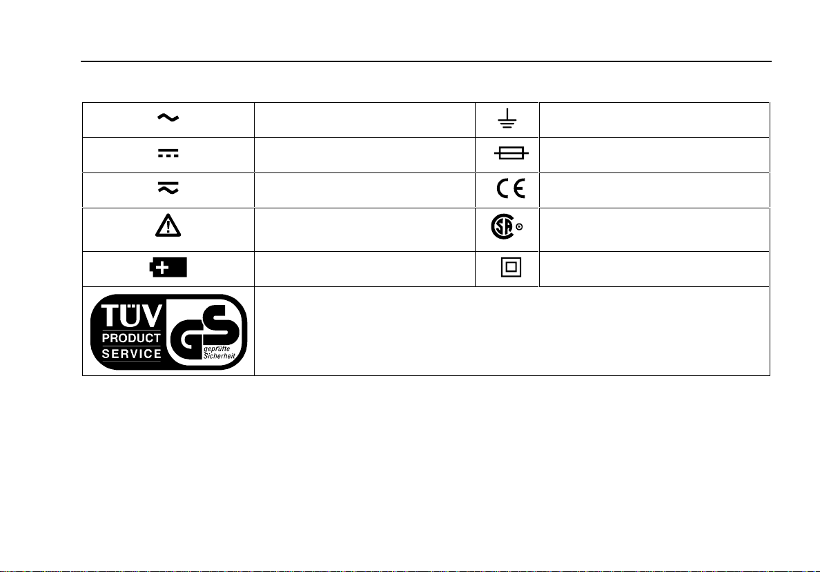
Table 1. International Electrical Symbols
AC (Alternating Current) Earth ground
DC (Direct Current) Fuse
AC or DC Conforms to European Union directives
Contacting Fluke
Refer to the manual for information
about this feature.
Battery Double insulated
Inspected and licensed by TÜV Product Services.
Conforms to relevant Canadian
Standards Association directives
3
Page 8

80 Series III
Users Manual
Your Meter’s Features
Tables 2 through 5 briefly describe your meter’s features.
You can find more detailed information about the features
in the Users Manual (on the CD-ROM).
Table 2. Inputs
Terminal Description
A Input for 0 A to 10.00 A current
measurements
mA µA Input for 0 µA to 400 mA current
measurements
COM Return terminal for all measurements
V eG Input for voltage, continuity, resistance,
diode, capacitance, frequency, and duty
cycle measurements
4
Page 9

Table 3. Rotary Switch Positions
Switch Position Function
K AC voltage measurement
L DC voltage measurement
Your Meter’s Features
d
mV
400 mV dc voltage range
ReE R Continuity test
e Resistance measurement
E Capacitance measurement
G Diode test
mA
DC or AC current measurements from 0 mA to 10.00 A
A
µA DC or AC current measurements from 0 µA to 4000 µA
5
Page 10

80 Series III
Users Manual
Table 4. Pushbuttons
Button Function Button Function
U
(Blue
button)
M
K
I
6
ReE
mA/A, µA
Power-up
Any switch
position
Power-up
Any switch
position
Power-up For servicing purposes only.
Any switch
position
MIN MAX
recording
Frequency
counter
Selects capacitance.
Switches between dc and ac current.
Disables automatic power-off feature.
Starts recording of minimum and maximum values. Steps the display through MIN,
MAX, AVG (average), and present readings.
Enables high-accuracy 1-second response time for MIN MAX recording.
Switches between the ranges available for the selected function. To return to
autoranging, hold the button down for 1 second.
Manually selecting a range causes the meter to exit the Touch Hold®, MIN MAX, and
REL (relative) modes.
Touch Hold captures the present reading on the display. When a new, stable reading
is detected, the meter beeps and displays the new reading.
Stops and starts recording without erasing recorded values.
Stops and starts the frequency counter.
Page 11

Table 4. Pushbuttons (cont.)
Button Function Button Function
Your Meter’s Features
b Model 87:
yellow button
b Models
83, 85: gray
button
T
C
(Relative
mode)
F
Any switch
position
Continuity
ReE
MIN MAX
recording
Power-up
Any switch
position
Power-up
Any switch
position
Power-up
Turns the backlight on and off.
For Model 87, hold the yellow button down for one second to enter the
4-1/2 digit mode. To return to the 3-1/2 digit mode, hold the button down only until all
display segments turn on (about one second).
Turns the continuity beeper on and off.
On Model 87, switches between 250 µs and 100 ms or 1 s response times.
Disables the beeper for all functions.
Stores the present reading as a reference for subsequent readings. The display is
zeroed, and the stored reading is subtracted from all subsequent readings.
For Models 83 and 85, enables zoom mode for the bar graph.
Starts the frequency counter.
Press again to enter duty cycle mode.
Provides >4000 MΩ input impedance for the 400 mV dc range.
7
Page 12

80 Series III
Users Manual
9
6
5
4
3
7
8
10
10
2
1
12
13
10
11
iy1f.eps
Figure 1. Display Features (Model 87 Shown)
8
Page 13

Table 5. Display Features
Number Feature Indication
Your Meter’s Features
A
B
C
±
Q
S
D
-
E
F
G
H
I AC DC
J A, µA, mA
AUTO
100 ms
MAX MIN AVG
Polarity indicator for the analog bar graph.
Relative (REL) mode is active.
The continuity beeper is on.
Indicates negative readings. In relative mode, this sign indicates that the present
input is less than the stored reference.
The battery is low. WWarning: To avoid false readings, which could lead to
possible electric shock or personal injury, replace the battery as soon as the
battery indicator appears.
The meter is in autorange mode and automatically selects the range with the best
resolution.
Indicators for minimum-maximum recording mode.
Touch Hold is active.
Indicator for ac or dc voltage or current. AC voltage and current is displayed as an
rms (root mean square) value.
A: Amperes (amps). The unit of current.
µA: Microamp. 1 x 10
mA: Milliamp. 1 x 10
-6
or 0.000001 amperes.
-3
or 0.001 amperes.
9
Page 14

80 Series III
Users Manual
Table 5. Display Features (cont.)
Number Feature Indication
V, mV
µF, nF
nS
%
e, Me, ke
Hz, kHz, MHz
V: Volts. The unit of voltage.
mV: Millivolt. 1 x 10
F: Farad. The unit of capacitance.
µF: Microfarad. 1 x 10
nF: Nanofarad. 1 x 10
S: Siemen. The unit of conductance.
nS: Nanosiemen. 1 x 10
Percent. Used for duty cycle measurements.
Ω: Ohm. The unit of resistance.
MΩ: Megohm. 1 x 10
kΩ: Kilohm. 1 x 10
Hz: Hertz. The unit of frequency.
kHz: Kilohertz. 1 x 10
MHz: Megahertz. 1 x 10
-3
or 0.001 volts.
-6
or 0.000001 farads.
-9
or 0.000000001 farads.
-9
or 0.000000001 siemens.
6
or 1,000,000 ohms.
3
or 1000 ohms.
3
or 1000 hertz.
6
or 1,000,000 hertz.
K 4000 mV Displays the currently selected range.
L Analog bar graph Provides an analog indication of the present inputs.
10
M
0L
The input (or the relative value when in relative mode) is too large for the selected
range. For duty cycle measurements OL is displayed when the input signal stays high
or low.
Page 15

Analog Bar Graph
Power-Up Options
Holding a button down while turning the meter on
activates a power-up option. Table 4 includes the powerup options available. These options are also listed on the
back of the meter.
Automatic Power-Off
The meter automatically turns off if you do not turn the
rotary switch or press a button for 30 minutes. To disable
automatic power-off, hold down the blue button while
turning the meter on. Automatic power-off is always
disabled in MIN MAX recording mode.
Input Alert™ Feature
If a test lead is plugged into the mA/µA or A terminal, but
the rotary switch is not correctly set to the mA/µA or A
position, the beeper warns you by making a chirping
sound. This warning is intended to stop you from
attempting to measure voltage, continuity, resistance,
capacitance, or diode values when the leads are plugged
into a current terminal. Placing the probes across (in
parallel with) a powered circuit when a lead is plugged
into a current terminal can damage the circuit you are
testing and blow the meter’s fuse. This can happen
because the resistance through the meter’s current
terminals is very low, so the meter acts like a short circuit.
Analog Bar Graph
The analog bar graph functions like the needle on an
analog meter, but without the overshoot. The bar graph is
updated 40 times per second. Because the graph
responds 10 times faster than the digital display, it is
useful for making peak and null adjustments and
observing rapidly changing inputs.
Model 87 Bar Graph
Model 87’s bar graph consists of 32 segments. The
position of the pointer on the display represents the last
three digits of the digital display. For example, for inputs
of 500 Ω, 1500 Ω, and 2500 Ω, the pointer is near 0.5 on
the scale. If the last three digits are 999, the pointer is at
the far right of the scale. As the digits increment past 000,
the pointer wraps back to the left side of the display. The
polarity indicator at the left of the graph indicates the
polarity of the input.
Models 83 and 85 Bar Graph
The bar graph on Models 83 and 85 consists of 43
segments. The number of lit segments is relative to the
full-scale value of the selected range. The polarity
indicator at the left of the graph indicates the polarity of
the input. For example, if the 40 V range is selected, the
"4" on the scale represents 40 V. An input of -30 V would
11
Page 16

80 Series III
Users Manual
light the negative sign and the segments up to the "3" on
the scale.
If the input equals or exceeds the 4096 counts on a
manually-selected range, all segments are lit and±
appears to the right of the bar graph. The graph does not
operate with the capacitance or frequency counter
functions.
The bar graph on Models 83 and 85 also has a zoom
function, as described under "Zoom Mode".
4-1/2 Digit Mode (Model 87)
On a Model 87 meter, pressing the yellow button for one
second causes the meter to enter the high-resolution,
4-1/2 digit mode. Readings are displayed at 10 times the
normal resolution with a maximum display of 19,999
counts. The display is updated once per second. The
4-1/2 digit mode works in all modes except capacitance
and the 250 µs and 100 ms MIN MAX modes.
To return to the 3-1/2 digit mode, press the yellow button
only until all of the display segments turn on (about one
second).
MIN MAX Recording Mode
The MIN MAX mode records minimum and maximum
input values. When the inputs go below the recorded
minimum value or above the recorded maximum value,
the meter beeps and records the new value. This mode
can be used to capture intermittent readings, record
maximum readings while you are away, or record
readings while you are operating the equipment under
test and cannot watch the meter. MIN MAX mode can
also calculate an average of all readings taken since the
MIN MAX mode was activated. To use MIN MAX mode,
refer to the functions in Table 6.
Response time is the length of time an input must stay at
a new value to be recorded. A shorter response time
captures shorter events, but with decreased accuracy.
Changing the response time erases all recorded
readings. Models 83 and 85 have 100 millisecond and
1 second response times; Model 87 has 1 second,
100 millisecond, and 250 µs (peak) response times. The
250 µs response time is indicated by "1 ms" on the
display.
The 100 millisecond response time is best for recording
power supply surges, inrush currents, and finding
intermittent failures. This response time follows the
update time of the analog display.
The high-accuracy 1 second response time has the full
accuracy of the meter and is best for recording power
supply drift, line voltage changes, or circuit performance
12
Page 17

MIN MAX Recording Mode
while line voltage, temperature, load, or some other
parameter is being changed.
The true average value (AVG) displayed in the 100 ms
and 1 s modes is the mathematical integral of all readings
Table 6. MIN MAX Functions
Button MIN MAX Function
M Enter MIN MAX recording mode. The meter is locked in the range displayed before you
entered MIN MAX mode. (Select the desired measurement function and range before
entering MIN MAX.) The meter beeps each time a new minimum or maximum value is
recorded.
M
(While in MIN MAX mode)
T
PEAK MIN MAX
Scroll through minimum (MIN), maximum (MAX), and average (AVG) values.
Model 87 only: Select 100 ms or 250 µs response time. (The 250 µs response time is
indicated by "1 ms" on the display.) Stored values are erased. The present and AVG
(average) values are not available when 250 µs is selected.
I Stop recording without erasing stored values. Press again to resume recording.
M
(hold for 1 second)
Hold down M
while turning the meter on
Exit MIN MAX mode. Stored values are erased. The meter stays in the selected range.
Select 1 s high-accuracy response time. See text under "MIN MAX Recording Mode" for
more explanation. MIN MAX readings for the frequency counter are recorded only in the
high-accuracy mode.
taken since you started recording. The average reading is
useful for smoothing out unstable inputs, calculating
power consumption, or estimating the percent of time a
circuit is active.
13
Page 18

80 Series III
Users Manual
Touch Hold ® Mode
WWarning
The Touch Hold mode will not capture
unstable or noisy readings. Do not use
Touch Hold mode to determine that circuits
are without power.
The Touch Hold mode captures the present reading on
the display. When a new, stable reading is detected, the
meter beeps and displays the new reading. To enter or
exit Touch Hold mode, press
I.
Relative Mode
Selecting relative mode ( C) causes the meter to
zero the display and store the present reading as the
reference for subsequent measurements. The meter is
locked into the range selected when you pressed
C. Press Cagain to exit this mode.
In relative mode, the reading shown is always the
difference between the present reading and the stored
reference value. For example, if the stored reference
value is 15.00 V and the present reading is 14.10 V, the
display shows -0.90 V.
On Model 87, the relative mode does not change the
operation of the analog display. Selecting relative mode
on a Model 83 or 85 meter causes the bar graph to enter
Zoom mode. In zoom mode, the center of the graph
represents zero and the sensitivity of the bar graph
increases by a factor of 10.
14
Page 19

Table 7. Replacement Parts
Item Description PN Quantity
BT1 Battery, 9 V 614487 1
F1 W Fuse, 0.440 A, 1000 V, FAST 943121 1
F2 W Fuse, 11 A, 1000 V, FAST 803293 1
H1 Screw, Case 832246 3
MP1 Foot, Non-Skid 824466 2
MP2 O-Ring, Input Receptacle 831933 1
TM1 CD-ROM (contains Users Manual) 1611720 1
TM2 Getting Started Manual 1611712 1
TM3 Quick Reference Guide, Fluke 80 Series III 688168 1
TM4 Service Manual 688645 Optional
WTo ensure safety, use exact replacement only.
15
Page 20

80 Series III
Users Manual
Specifications
Maximum Voltage between any Terminal and Earth Ground: 1000 V rms
WFuse Protection for mA or µA inputs: 44/100 A, 1000 V FAST Fuse
WFuse Protection for A input: 11 A, 1000 V FAST Fuse
Display: Digital: 4000 counts updates 4/sec ; (Model 87 also has 19,999 counts i n 4½ -di git mode, updates 1/sec. ). Analog: updates
40/sec. Frequency: 19,999 counts, updates 3/sec at >10 Hz. Model 87: 4 x 32 segments (equivalent to 128); Models 83, 85: 43 segments.
Temperature: Operating: -20°C to +55°C; Storage: -40°C to +60°C
Altitude: Operating: 2000 m; Storage: 10,000 m
Temperature Coefficient: 0.05 x (speci fied accuracy)/ °C (<18°C or >28°C)
Electromagnetic Compatibility: In an RF field of 3 V/m total accuracy = specified accuracy except: Models 85,87: Total Accuracy =
Specified Accuracy + 0.4% of range above 800 MHz (µADC only ). (mVAC and µAAC unspecified). Model 83: Total Accuracy = Specified
Accuracy + 5% of range abov e 300 MHz (µADC only). (VDC unspecified).
Relative Humidity: 0% to 90% (0°C to 35°C); 0% to 70% (35°C to 55°C)
Battery Type: 9 V zinc, NEDA 1604 or 6F22 or 006P
Battery Life: 400 hrs typical wit h al kaline (with backlight of f)
Shock Vibration: Per MIL-T-28800 for a Class 2 inst rum ent
Size (HxWxL): 1.25 in x 3.41 in x 7.35 in (3.1 cm x 8.6 cm x 18.6 cm)
Size with Holster and Flex-Stand: 2.06 in x 3.86 in x 7.93 in (5.2 cm x 9.8 cm x 20.1 cm)
Weight: 12.5 oz (355 g)
Weight with Holster and Flex-Stand: 22.0 oz (624 g)
Safety: Complies with ANSI/ISA S82.01-1994, CSA 22.2 No. 1010.1:1992 to 1000 V Overvoltage Category III. UL listed to UL3111-1.
Licensed by TÜV to EN61010-1.
16
Page 21

Table 8. Models 85 and 87 AC Voltage Function Specifications
Specifications
Function Range Resolution Accuracy
50 Hz - 60 Hz 45 Hz - 1 kHz 1 kHz - 5 kHz 5 kHz - 20 kHz
K
3
400.0 mV
4.000 V
40.00 V
400.0 V
1000 V
0.1 mV
0.001 V
0.01 V
0.1 V
1 V
±(0.7% + 4)
±(0.7% + 2)
±(0.7% + 2)
±(0.7% + 2)
±(0.7% + 2)
±(1.0% + 4)
±(1.0% + 4)
±(1.0% + 4)
±(1.0% + 4)
±(1.0% + 4)
5
1
±(2.0% + 4)
±(2.0% + 4)
±(2.0% + 4)
±(2.0% + 4)
unspecified
2
±(2.0% + 20)
±(2.0% + 20)
4
±(2.0% + 20)
unspecified
unspecified
1. Accuracy is giv en as ±([% of reading] + [number of least significant digi t s]) at 18°C to 28°C, with relat i ve humidity up to 90%, for a
period of one year after calibrati on. For M odel 87 i n the 4 ½-digit mode, multiply the number of least significant digits (counts) by 10.
AC conversions are ac-coupl ed and valid from 5% to 100% of range. M odel s 85 and 87 are true rms responding. AC cres t factor can
be up to 3 at full scale, 6 at hal f scale. For non-sinusoidal wave forms add -(2% Rdg + 2% full scale) typical, for a c rest factor up to 3.
2. Below 10% of range, add 6 counts.
3. Models 85 and 87 are true rms responding met ers. When the input leads are shorted together in the ac functions, the meters display
a reading (typically <25 count s) that is caused by int ernal am pl i fier noise. The accuracy on M odel s 85 and 87 is not significantly
affected by this i nt ernal offset when measuring inputs that are within 5% to 100% of the selected range. When the rms val ue of the
two values (5% of range and internal offset) is calculated, the effect is m i ni m al as shown in the following example where 20.0 = 5% of
400 mV range, and 2.5 is the internal offset: RMS = SQRT[(20.0)
2
+ (2.5)2] = 20.16. If you use the RE L function to zero the display
when using the ac functions, a constant error that is equal to the internal of fset will result.
4. Frequency range: 1 kHz to 2.5 kHz.
5. Below 10% of range, add 16 counts.
17
Page 22

80 Series III
Users Manual
Table 9. Model 83 AC Voltage Function Specifications
Function Range Resolution Accuracy
50 Hz - 60 Hz 45 Hz - 1 kHz 1 kHz - 5 kHz
2
K
1. See the first sentenc e i n Tabl e 8 for a complete explanation of ac curacy.
2. Below a reading of 200 counts, add 10 c ount s.
3. Frequency range: 1 kHz to 2.5 kHz.
400.0 mV
4.000 V
40.00 V
400.0 V
1000 V
0.1 mV
0.001 V
0.01 V
0.1 V
1 V
±(0.5% + 4)
±(0.5% + 2)
±(0.5% + 2)
±(0.5% + 2)
±(0.5% + 2)
±(1.0% + 4)
±(1.0% + 4)
±(1.0% + 4)
±(1.0% + 4)
±(1.0% + 4)
1
±(2.0% + 4)
±(2.0% + 4)
±(2.0% + 4)
±(2.0% + 4)
unspecified
3
18
Page 23

Table 10. DC Voltage, Resistance, and Conductance Function Specifications
Specifications
Accuracy
Function Range Resolution Model 83 Model 85 Model 87
2
±(0.08% + 1)
±(0.08% + 1)
±(0.08% + 1)
±(0.08% + 1)
±(0.2% + 2)
±(0.2% + 1)
±(0.2% + 1)
±(0.6% + 1)
±(0.6% + 1)
±(1.0% + 3)
±(1.0% + 10)
L
F
mV
e
nS
1. See the first sentenc e i n Tabl e 8 for a complete explanation of ac curacy.
2. When using the REL ∆ function to compensate for offsets.
4.000 V
40.00 V
400.0 V
1000 V
400.0 mV 0.1 mV ±(0.3% + 1) ±(0.1% + 1) ±(0.1% + 1)
400.0 Ω
4.000 kΩ
40.00 kΩ
400.0 kΩ
4.000 MΩ
40.00 MΩ
40.00 nS
0.001 V
0.01 V
0.1 V
1 V
0.1 Ω
0.001 kΩ
0.01 kΩ
0.1 kΩ
0.001 MΩ
0.01 MΩ
0.01 nS
±(0.1% + 1)
±(0.1% + 1)
±(0.1% + 1)
±(0.1% + 1)
±(0.4% + 2)
±(0.4% + 1)
±(0.4% + 1)
±(0.7% + 1)
±(0.7% + 1)
±(1.0% + 3)
±(1.0% + 10)
1
2
±(0.05% + 1)
±(0.05% + 1)
±(0.05% + 1)
±(0.05% + 1)
±(0.2% + 2)
±(0.2% + 1)
±(0.2% + 1)
±(0.6% + 1)
±(0.6% + 1)
±(1.0% + 3)
±(1.0% + 10)
2
19
Page 24

80 Series III
Users Manual
Table 11. Current Function Specifications
Function Range Resolution Model 83
mA
\
(45 Hz to 2 kHz)
40.00 mA
400.0 mA
4000 mA
10.00 A
0.01 mA
0.1 mA
1 mA
5
0.01 A
±(1.2% + 2)
±(1.2% + 2)
±(1.2% + 2)
±(1.2% + 2)
2
6
6
6
6
Accuracy
Model 85
±(1.0% + 2)
±(1.0% + 2)
±(1.0% + 2)
±(1.0% + 2)
3, 4
1
6
6
6
6
Model 87
±(1.0% + 2)
±(1.0% + 2)
±(1.0% + 2)
±(1.0% + 2)
3, 4
mA
[
40.00 mA
400.0 mA
4000 mA
10.00 A
0.01 mA
0.1 mA
1 mA
5
0.01 A
±(0.4% + 4)
±(0.4% + 2)
±(0.4% + 4)
±(0.4% + 2)
±(0.2% + 4)
±(0.2% + 2)
±(0.2% + 4)
±(0.2% + 2)
1. See the first sentenc e i n Tabl e 8 for a complete explanation of ac curacy.
2. AC conversion for Model 83 is ac coupled and calibrated to the rms value of a sinewave input.
3. AC conversions for Models 85 and 87 are ac coupled, true rms respondi ng, and valid from 5% to 100% of range.
4. See note 3 in Table 8.
W
10 A continuous; 20 A for 30 s econds maximum; >10 A: uns pecified.
5.
6. Below a reading of 200 counts, add 10 c ount s.
±(0.2% + 4)
±(0.2% + 2)
±(0.2% + 4)
±(0.2% + 2)
Burden Voltage
(typical)
1.8 mV/mA
1.8 mV/mA
0.03 V/A
0.03 V/A
1.8 mV/mA
1.8 mV/mA
0.03 V/A
0.03 V/A
20
Page 25

Table 11. Current Function Specifications (continued)
Specifications
1
3, 4
Model 87
5
5
3, 4
±(1.0% + 2)
±(1.0% + 2)
Function Range Resolution Model 83
µA B
(45 Hz to 2 kHz)
400.0 µA
4000 µA
0.1 µA
1 µA
±(1.2% + 2)
±(1.2% + 2)
Accuracy
2
5
5
Model 85
±(1.0% + 2)
±(1.0% + 2)
µAF
400.0 µA
4000 µA
0.1 µA
1 µA
±(0.4% + 4)
±(0.4% + 2)
±(0.2% + 4)
±(0.2% + 2)
1. See the first sentenc e i n Tabl e 8 for a complete explanation of ac curacy.
2. AC conversion for Model 83 is ac coupled and calibrated to the rms value of a sinewave input.
3. AC conversions for Models 85 and 87 are ac coupled, true rms respondi ng, and valid from 5% to 100% of range.
4. See note 3 in Table 8.
5. Below a reading of 200 counts, add 10 c ount s.
±(0.2% + 4)
±(0.2% + 2)
Burden
Voltage
(typical)
100 µV/µA
100 µV/µA
100 µV/µA
100 µV/µA
21
Page 26

80 Series III
Users Manual
Table 12. Capacitance and Diode Function Specifications
Function Range Resolution Accuracy
E
G
1. With a film capacitor or better, using Relative mode t o zero residual. See the first sentence in Table 8 for a complete explanation of
accuracy.
5.00 nF
0.0500 µF
0.500 µF
5.00 µF
3.000 V 0.001 V ±(2% + 1)
0.01 nF
0.0001 µF
0.001 µF
0.01 µF
±(1% + 3)
±(1% + 3)
±(1% + 3)
±(1.9% + 3)
1
Table 13. Frequency Counter Specifications
Function Range Resolution Accuracy
Frequency
(0.5 Hz to 200 kHz,
pulse width >2 µs)
1. See the first sentenc e i n Tabl e 8 for a complete explanation of ac curacy.
199.99
1999.9
19.999 kHz
199.99 kHz
>200 kHz
0.01 Hz
0.1 Hz
0.001 kHz
0.01 kHz
0.1 kHz
±(0.005% + 1)
±(0.005% + 1)
±(0.005% + 1)
±(0.005% + 1)
unspecified
1
22
Page 27

Input Range
Specifications
Table 14. Frequency Counter Sensitivity and Trigger Levels
Minimum Sensitivity (RMS Sinewave) Approximate Trigger Level
1
5 Hz - 20 kHz 0.5 Hz - 200 kHz (DC V o l tage Function)
400 mV dc
400 mV dc
4 V
40 V
400 V
1000 V
Duty Cycle Range Accuracy
0.0 to 99.9% Withi n ±(0.05% per kHz + 0.1%) of full scale for a 5 V logic famil y input on the 4 V dc range.
1. Maximum input for spec i f i ed accuracy = 10X Range or 1000 V.
70 mV (to 400 Hz)
150 mV
0.3 V
3 V
30 V
300 V
Within ±((0.06 x Voltage Range/ Input Voltage) x 100%) of full scale for sine wave inputs on ac voltage ranges.
70 mV (to 400 Hz)
150 mV
0.7 V
7 V (≤140 kHz)
70 V (≤14.0 kHz)
700 V (≤1.4 kHz)
40 mV
1.7 V
4 V
40 V
400 V
23
Page 28

80 Series III
Users Manual
Table 15. Electrical Characteristics of the Terminals
Common Mode Rejection
Ratio
(1 kΩ unbalance) Normal Mode Rejection
Function
Overload
Protection
1
Input
Impedance
(nominal)
L 1000 V rms 10 MΩ<100 pF >120 dB at dc, 50 Hz or 60 Hz >60 dB at 50 Hz or 60 Hz
F
mV
K 1000 V rms 10 MΩ<100 pF
1000 V rms 10 MΩ<100 pF >120 dB at dc, 50 Hz or 60 Hz >60 dB at 50 Hz or 60 Hz
>60 dB, dc to 60 Hz
(ac-coupled)
Open Circuit
Test Voltage
Full Scale Voltage Typical Short Circuit Current
To 4.0 MΩ 40 MΩ or nS 400 Ω 4 k 40 k 400 k 4 M 40 M
e 1000 V rms <1.3 V dc <450 mV dc <1.3 V dc 200 µA 80 µA 12 µA1.4 µA0.2 µA0.2 µA
G 1000 V rms <3.9 V dc 3.000 V dc 0.6 mA typical
1. 106 V Hz max
24
Page 29

Table 16. MIN MAX Recording Specifications
Model Nominal Response Accuracy
Specifications
83 100 ms to 80%
1 s
85, 87 100 ms t o 80%
(DC functions)
120 ms to 80%
(AC functions)
1 s
250 µs
(Model 87 only)
Specified accuracy ±12 counts for changes >200 ms in duration (±40 counts in ac with beeper on)
Same as specified accuracy for changes >2 seconds in duration (±40 counts in ac with beeper on)
Specified accuracy ±12 counts for changes >200 ms in duration
Specified accuracy ±40 counts for changes >350 ms and inputs >25% of range
Same as specified accuracy for changes >2 seconds in duration
Specified accuracy ±100 counts for changes >250 µs in duration
(± 250 digits typical f or m V, 400 µA dc, 40 mA dc, 4000 mA dc)
25
Page 30

80 Series III
Users Manual
26
 Loading...