

Page 1
80i-110s
AC/DC Current Probe
Instructions
Introduction
The Fluke 80i-110s (the Probe or Product) is a clamp-on AC/DC Current
Probe that reproduces current waveforms found in commercial and industrial
power distribution systems. The Probe performance is optimized for accurate
reproduction of currents at line frequency and up to the 50
waveform. The 80i-110s is also compatible with any instrument capable of
millivolt measurements.
The Probe provides these benefits:
• Accurate AC, DC, and AC+DC current measurements for Electrical,
Electronic, and Automotive applications.
• Shielded for high-noise immunity around electronic motor drives and
ignition systems.
• Wide measurement range from 50 mA to 100 A, useful to 10 mA.
• Jaw shaped for easy access to cramped spaces.
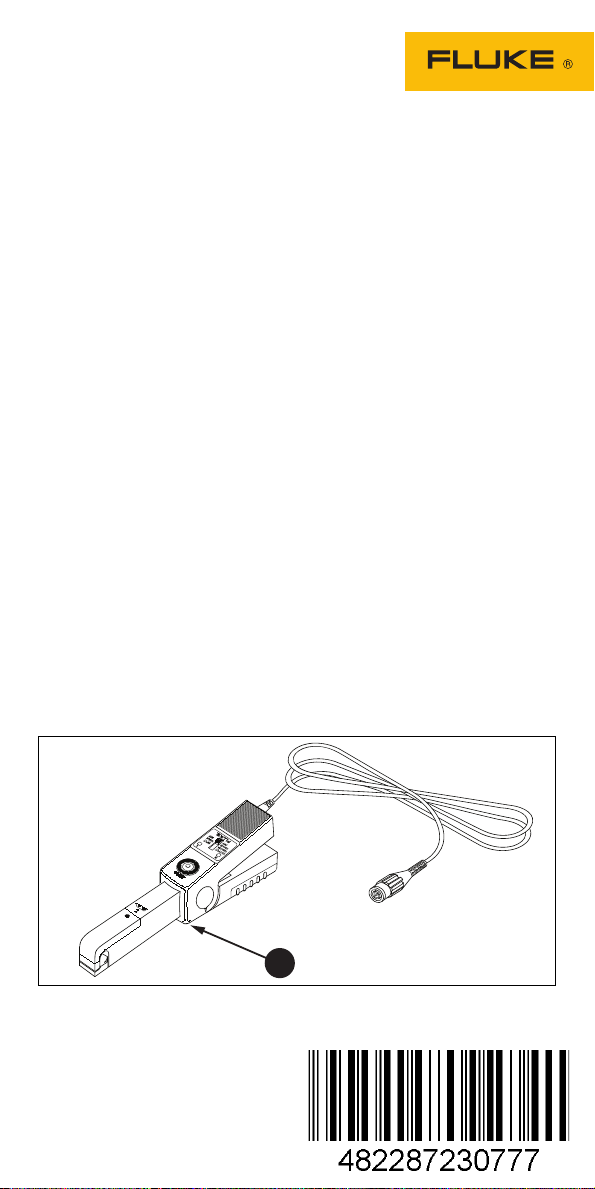
• Tactile barrier (see Figure 1, item
• Safety-designed 600 V insuIated BNC - compatible with Fluke
ScopeMeter
oscilloscopes.
• Selectable output of 10 millivolts/1 amp for the 100 A range, and
100 mV/1 A for the 10 A range.
®
test tools, Power Harmonic analyzers, and
).
th
harmonic
1
Figure 1. 80i-110s AC/DC Current Probe
PN 4862926 October 2005, Rev. 1, 1/17
©2005-2017 Fluke Corporation.
All rights reserved. Specifications are
subject to change without notification.
All product names are trademarks of their
respective companies.
Page 2

How to Contact Fluke
To contact Fluke, call one of the following telephone numbers:
• Technical Support USA: 1-800-44-FLUKE (1-800-443-5853)
• Calibration/Repair USA: 1-888-99-FLUKE (1-888-993-5853)
• Canada: 1-800-36-FLUKE (1-800-363-5853)
• Europe: +31 402-675-200
• Japan: +81-3-6714-3114
• Singapore: +65-6799-5566
• Anywhere in the world: +1-425-446-5500
To view, print, or download the latest manual supplement, visit
http://us.fluke.com/usen/support/manuals
.
Go to www.fluke.com
to register your product and find more information.
Safety
A Warning identifies conditions and procedures that are dangerous to the
user.
Warning
To prevent personal injury and for safe operation of the Product:
• Read all safety information before you use the Product.
• Carefully read all instructions.
• Do not use the Product if it is altered or damaged.
• Do not alter the Product and use only as specified, or the
protection supplied by the Product can be compromised.
• Comply with local and national safety codes. Use personal
protective equipment (approved rubber gloves, face
protection, and flame-resistant clothes) to prevent shock and
arc blast injury where hazardous live conductors are
exposed.
• Hold the Product behind the tactile barrier.
• Before each use, examine the Product. Look for cracks or
missing pieces of the clamp housing or output cable
insulation. Also look for loose or weakened components.
Carefully examine the insulation around the jaws.
• Do not touch voltages >30 V ac rms, 42 V ac peak, or 60 V dc.
• Use the Clamp only on insulated conductors. Use caution
around bare conductors or bus bars. To prevent electrical
shock, do not touch the conductor.
Page 3

Symbols
Symbol Definition
WARNING - RISK OF DANGER.
WARNING. HAZARDOUS VOLTAGE. Risk of electric shock.
Consult user documentation.
Double Insulated
Earth
Battery
Application around and removal from uninsulated hazardous live
conductors is permitted.
Conforms to European Union directives.
Conforms to relevant Australian Safety and EMC standards.
Measurement Category III is applicable to test and measuring
circuits connected to the distribution part of the building’s lowvoltage MAINS installation.
This product complies with the WEEE Directive marking
requirements. The affixed label indicates that you must not
discard this electrical/electronic product in domestic household
waste. Product Category: With reference to the equipment types
in the WEEE Directive Annex I, this product is classed as
category 9 "Monitoring and Control Instrumentation" product. Do
not dispose of this product as unsorted municipal waste.
Before You Start
These items are included in the shipment box:
• AC/DC Current Probe, 80i-110s
• Instructions (this document)
• 9 volt Battery, type IEC 6LR61
Check the contents of the box for completeness. If something in the box is
damaged or missing, contact your distributor or the nearest sales or service
office.
Page 4
Battery
Warning
To prevent electrical shock, unclamp the Probe from any
conductor, and disconnect the Scopemeter test tool or any
other measurement device before you install or replace the
battery.
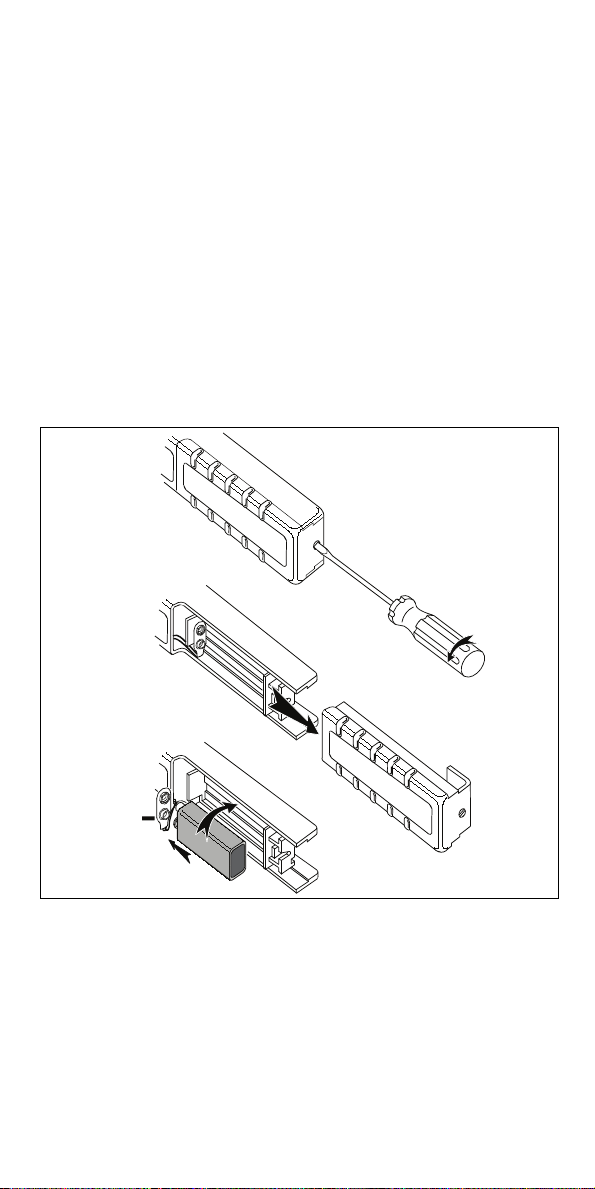
Before the first use, install the battery. See Figure 2.
To install the battery:
1. Unclamp the Probe from any conductor and disconnect the
ScopeMeter test tool or any other measurement device.
2. Make sure that the Probe is in the OFF position.
3. Locate the battery cover on the handle and loosen the screw with a flatblade screwdriver.
4. Slide the battery cover away from the Probe.
5. Install the battery (IEC 6LR61). Arrange the battery leads so that they
are not pinched between the handle bottom and the battery cover.
6. Reinstall the battery cover and secure the screw.
+
Figure 2. Battery Installation
Warning
To prevent possible electrical shock, fire, or personal injury,
replace the batteries when the low battery indicator shows to
prevent incorrect measurements.
Page 5

Compatibility
The Product is compatible with any Fluke ScopeMeter test tool, Power
Harmonics Analyzer, Oscilloscope, Multimeter, or other voltage measurement
device with these features:
• BNC input connector (PN PM9081/001 BNC-to-banana adapter) for
use with standard inputs on a digital multimeter (DMM).
• Input accuracy of 2 % or better to take full advantage of the accuracy
of the Probe.
• Input impedance of ≥1 MΩ in parallel with a maximum of 100 pF.
• A passband of more than four times the frequency of the waveform to
be measured.
Instructions
To use the Probe:
1. Connect the Probe to the input on the measuring instrument. When
the ScopeMeter test tool or an oscilloscope is used, it must have
DC-coupled input. When you are using a digital multimeter, use the
BNC-to- banana adapter (PM9081/001) to connect the Probe to the
input.
2. On the Probe, select the least sensitive range (10 mV/A). Make sure that
the green ON-indicator lights. See Figure 4 for selector switch and green
On indicator locations.
3. On the Probe, rotate the ZERO thumbwheel to adjust the reading to
zero. See Figure 4 for the ZERO rotary knob location.
4. Select the appropriate probe sensitivity on your ScopeMeter test tool or
oscilloscope.
5. Clamp the Probe around the conductor. Make sure that the arrow mark
on the jaw of the Probe points toward the correct orientation. See
Figure 3.
Figure 3. Current Probe Orientation
6. Observe the current value or waveform on your display or the current
value readout on the multimeter.
7. On the ScopeMeter test tool, adjust the vertical range knob and time
division knob for the best display.
8. If the red OL-indicator lights, the Probe is in overload mode.
Page 6

9. At completion, set the range selection switch to OFF again. A
X
.
X
X
A
measurement setup with the Probe and a ScopeMeter test tool is shown
in Figure 4.
Figure 4. Measurement Setup
Measurement Guidelines
Use these guidelines to position the jaws:
• Center the conductor inside the jaws.
• Position the Probe perpendicular to the conductor.
• Make sure that the arrow marked on the jaw of the Probe
points toward the correct direction.
Use these guidelines to take measurements:
• If possible, avoid measurements close to other current-carrying
conductors.
• On the Probe, the 100 mV/A range offers the best accuracy.
Maintenance
Before each use, inspect the Probe. Look for cracks or missing portions of the
housing and output cable insulating cover and for loose or weakened
components. Pay particular attention to the insulation surrounding the jaws. If
a Probe fails this inspection, tape it shut to prevent unintended operation. To
check Probe performance, complete the Performance Verification procedure.
Warning
To avoid electric shock:
• Do not perform any service procedures unless you are
qualified to do so.
• Read the "Safety" information at the beginning of this
instruction sheet before proceeding.
Page 7

If the Probe does not perform properly, use these steps to help isolate the
problem:
1. Test the battery. Be sure that the green ON-indicator lights when you
select the 10 mV/A range or the 100 mV/A range.
2. Inspect the jaw mating surface for cleanliness. If any foreign material is
present, the jaws will not close properly and errors will result.
3. Verify that the Probe is zeroed properly. For zeroing be sure that the
ScopeMeter test tool or oscilloscope is DC-coupled.
4. Verify that the function selection on the ScopeMeter test tool or
oscilloscope is correct, for example, the display vertical resolution is not
too low or too high.
Repairs or service not covered in this document must be performed only at a
Fluke Service Center. A Probe under warranty will be repaired or replaced (at
Fluke's discretion) and returned at no charge.
Cleaning and Storage
Periodically wipe the case with a damp cloth and detergent. Do not use
abrasives or solvents. Open the jaws and wipe the magnetic pole pieces with
a lightly oiled cloth. Do not allow rust or corrosion to form on the magnetic core
ends.
If the Probe is not used for long time periods (>60 days) the battery should be
removed and stored separately.
Accessories
An adapter accessory is required to use the Probe with a digital
multimeter. The BNC-to-Banana Adapter, Fluke Part PM9081/001, is
available to order.
Specifications
Maximum Voltage between any
Terminal and Earth Ground.............. 600 V
Dimensions....................................... 67 mm x 231 mm x 36 mm
Weight ..............................................330 g (11.6 oz), battery included
Output Cable ....................................1.6 m (63 in)
Maximum Conductor Size ................ 11.8 mm (0.46 in)
Maximum Jaw Opening.................... 12.5 mm (0.49 in)
Temperature
Operating.................................. 0 °C to 50 °C (32 °F to 122 °F)
Storage..................................... -30 °C to +70 °C (-22 °F to +158 °F)
Relative Humidity (Operating)
0 % to 85 %.............................. 0 °C to 35 °C (32 °F to 95 °F)
0 % to 45 %.............................. 35 °C to 50 °C (95 °F to 122 °F)
Altitude
Operating.................................. <2000 m (<6560 ft)
Storage..................................... <12 000 m (<40 000 ft)
Demagnetize Probe.......................... Open and close Probe jaws several
(2.6 in x 9.1 in x 1.4 in)
times
Page 8

Battery
Type ......................................... 9 volt, IEC 6LR61
Consumption............................ 8.6 mA typical
12 mA maximum
Service life with Alkaline IEC 6LR61 battery
Typical.............................. 55 hours
Minimum........................... 40 hours
Battery indicator (ON)............... Green LED dims when battery
voltage is <6.5 V
Safety
General..................................... IEC 61010-1: Pollution Degree 2
Measurement ........................... IEC 61010-2-032: CAT III 600 V
Electromagnetic Compatibility (EMC)
International.............................. IEC 61326-1: Portable
Electromagnetic Environment
CISPR 11: Group 1, Class A
Group 1: Equipment has intentionally generated and/or use
conductively coupled radio-frequency energy which is necessary for
the internal functioning of the equipment itself.
Class A: Equipment is suitable for use in all establishments other
than domestic and those directly connected to a low voltage power
supply network which supplies buildings used for domestic purposes.
There may be potential difficulties in ensuring electromagnetic
compatibility in other environments, due to conducted and radiated
disturbances.
Caution: This equipment is not intended for use in residential
environments and may not provide adequate protection to radio
reception in such environments.
Emissions that exceed the levels required by CISPR 11 can occur
when the equipment is connected to a test object.
USA (FCC) ............................... 47 CFR 15 subpart B. This product is
considered an exempt device per
clause 15.103.
Electrical Specifications
Valid temperature............................. 23 °C ±3 °C (73 °F ±5 °F).
Current Ranges................................ 0 A dc to 10 A dc or ac peak
0 A dc to 100 A dc or ac peak
Output Signals.................................. 10 A range: 100 mV/A
100 A range: 10 mV/A
Basic Accuracy (DC to 1kHz):
Input Current
(DC or AC peak)
0 A to 10 A
0 A to 40 A
40 A to 80 A
80 A to 100 A
Range 100 mV/A Range 10 mV/A
<3 % of reading +50 mA
Error (after zero check)
-
-
-
<4 % of reading +50 mA
<12 % of reading +50 mA
<15 % of reading
-
Page 9

Extended Accuracy:
For other frequencies, refer to the appropriate input current range and add the error
listed below to the "Basic Accuracy" error.
Frequency
1 kHz to 5 kHz
5 kHz to 20 kHz
>20 kHz
Range 100 mV/A Range 10 mV/A
3 %
12 %
not specified
Additional Error
3 %
12 %
not specified
Input Load Impedance
(of host instrument) .......................... >1 MΩ in parallel with up to 100 pF
Useful Bandwidth (-3 dB) ................. 0 kHz to 100 kHz
Rise or Fall Time ..............................<4 μsec
Output noise level
Range 10 mV/A typical............. 480 μV pk-pk
Range 100 mV/A typical........... 3 mV pk-pk
Max. nondestructive current............. 0 kHz to 2 kHz 140 A peak
2 kHz to 10 kHz 110 A peak
10 kHz to 20 kHz 70 A peak
20 kHz to 50 kHz 30 A peak
50 kHz to 100 kHz 20 A peak
Temperature coefficient.................... 2000 ppm/°C max. for temperature
from 0 °C to 50 °C (32 °F to 132 °F)
Performance Verification
Verify Probe accuracy with the test setup shown in Figure 5. Required test
equipment is defined in Table 1. Toroid coil construction is illustrated in
Ta b le 2 .
To verify the Probe accuracy:
1. Set up connection.
2. Make the checks called for in Table 3 (100 mV/A).
3. Make the checks called for in Table 4 (10 mV/A).
Table 1. Required Test Equipment
Required Recommended
AD/DC Calibrator Fluke 5520A
Digital Multimeter (DMM) Fluke 45
Small insulated screwdriver Spectrol
Banana-to-BNC Adapter Fluke PM9081/001
10-turn Toroid Coil See Figure 6
Page 10

Figure 5. Performance Test and Calibration Setup
5520A
DMM
10.5 cm (4 in)
D
Table 2. Toroid Coil Construction
Item Description
D
10 turns wound on cylindrical form using 10-gauge magnet wire.
Remove form and tape coil together making sure 10 wires are
taped.
Tape
Fan out coil to approximately 270° with spacing 5 cm (2 in) using
tape to maintain coil shape.
Page 11

Table 3. Performance Test Points:
Current Range 0 A to 10 A (100 mV/A)
DC Measurement:
5520A
Settings
0.1 A 1 A 92 mV 108 mV
0.5 A 5 A 480 mV 520 mV
0.9 A 9 A 868 mV 932 mV
DC Amps
Measured
Low Limit
Output
High Limit
Output
AC Measurement:
5520A
Settings
0.1 A, 60 Hz 1 A 92 mV 108 mV
0.3 A, 400 Hz 3 A 286 mV 314 mV
0.5 A, 2 kHz 5 A 465 mV 535 mV
0.6 A, 4 kHz 6 A 559 mV 641 mV
RMS Amps
Measured
Table 4. Performance Test Points:
Current Range 0 A to 100 A (10 mV/A)
Low Limit
Output
High Limit
Output
DC Measurement:
5520A
Settings
1 A 10 A 95.5 mV 104.5 mV
3 A 30 A 287.5 mV 312.5 mV
DC Amps
Measured
Low Limit
Output
High Limit
Output
5 A 50 A 439.5 mV 560.5 mV
7 A 70 A 615.5 mV 784.5 mV
9 A 90 A 765.0 mV 1035.0 mV
AC Measurement:
5520A
Settings
1 A, 5 kHz 10 A 92.5 mV 107.5 mV
2 A, 1 kHz 20 A 185.5 mV 214.5 mV
3 A, 400 Hz 30 A 287.5 mV 312.5 mV
5 A, 400 Hz 50 A 439.5 mV 560.5 mV
7 A, 60 Hz 70 A 595.0 mV 805.0 mV
RMS Amps
Measured
Low Limit
Output
High Limit
Output
Page 12

LIMITED WARRANTY AND LIMITATION OF LIABILITY
This Fluke product will be free from defects in material and workmanship
for one year from the date of purchase. This warranty does not cover
fuses, disposable batteries, or damage from accident, neglect, misuse,
alteration, contamination, or abnormal conditions of operation or handling.
Resellers are not authorized to extend any other warranty on Fluke’s
behalf. To obtain service during the warranty period, contact your nearest
Fluke authorized service center to obtain return authorization information,
then send the product to that Service Center with a description of the
problem.
THIS WARRANTY IS YOUR ONLY REMEDY. NO OTHER WARRANTIES,
SUCH AS FITNESS FOR A PARTICULAR PURPOSE, ARE EXPRESSED
OR IMPLIED. FLUKE IS NOT LIABLE FOR ANY SPECIAL, INDIRECT,
INCIDENTAL OR CONSEQUENTIAL DAMAGES OR LOSSES, ARISING
FROM ANY CAUSE OR THEORY. Since some states or countries do not
allow the exclusion or limitation of an implied warranty or of incidental or
consequential damages, this limitation of liability may not apply to you.
Fluke Corporation
P.O. Box 9090
Everett, WA 98206-9090
U.S.A.
11/ 99
Fluke Europe B.V.
P.O. Box 1186
5602 BD Eindhoven
The Netherlands
 Loading...