

Fluke 80i-110s Instruction Manual
®
S
0
5
80i-110s
AC/DC Current Probe
Instruction Sheet
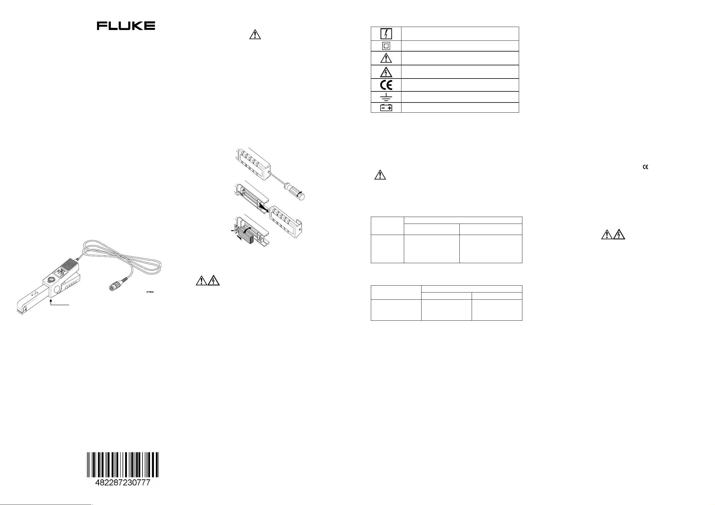
Introducing The Current Probe
• The Fluke 80i-110s is a clamp-on AC/DC Current Probe that
reproduces current waveforms found in modern commercial and
industrial power distribution systems. The probe's performance
is optimized for accurate reproduction of currents at line
frequency and up to the 50th harmonic waveform. The 80i-110s
is also compatible with any instrument capable of millivolt
measurements. The Current Probe (shown in Figure 1) provides
the following benefits:
• Accurate AC, DC and AC+DC current measurements for
Electrical, Electronic and Automotive applications.
• Shielded for high noise immunity around electronic motor drives
and ignition systems.
• Wide measurement range from 50 milliamps to 100 amps,
useful to 10 milliamps.
• Jaw shaped for easy access to cramped spaces.
• Safety-designed 600 volt insuIated BNC - compatible with Fluke
ScopeMeter® test tools, Power Harmonic analyzers, and
oscilloscopes.
• Selectable output of 10 millivolts per 1 amp for the 100 A range,
and 100 millivolts per 1 amp for the 10 A range.
Figure 1. 80i-110s AC/DC Current Probe
Unpacking
The following items should be included in your Current Probe box:
• AC/DC Current Probe, 80i-110s
• Instruction Sheet (this sheet)
• 9 volt Battery, type IEC 6LR61
Check the contents of the shipping box for completeness. If
something in the box has been damaged or missing, contact your
distributor or the nearest FLUKE sales or service office immediately.
4822 872 30777
October 2005
© 2005 Fluke Corporation.
All rights reserved.
Printed in the Netherlands.
All product names are trademarks
of their respective companies.
Tactile Indicator
Warning
To avoid electrical shock, unclamp the current probe
from any conductor, and disconnect the scopemeter
test tool or any other measurement device before
installing or replacing the battery.
At first use, remember to install the battery. Referring to Figure 2,
use the following procedure to install the battery:
1. Be sure that you have unclamped the Current Probe from any
conductor and have disconnected the ScopeMeter test tool or
any other measurement device.
2. Be sure that the Current Probe is in the OFF position.
3. Locate the battery cover on the handle. (see Figure 2.) Loosen
the screw with a flat-blade screwdriver.
4. Slide the battery cover away from the Current Probe.
5. Install the battery (IEC 6LR61) as shown in Figure 2. Arrange
the battery leads so that they will not be pinched between the
handle bottom and the battery cover.
6. Reinstall the battery cover and secure the screw.
+
T77
Figure 2. Installing the Battery
Safety information
Installing The Battery
To ensure safe operation and service of the Current Probe,
follow these instructions:
• Read the operating instructions before use and follow all safety
• Use the Current Probe only as specified in the operating
• Adhere to local and national safety codes. Individual protective
• Do not hold the Current Probe anywhere beyond the tactile
• Before each use, inspect the Current Probe. Look for cracks or
• Check the magnetic mating surfaces of the Current Probe jaws;
• Never use the Current Probe on a circuit with voltages higher
• Use extreme caution when working around bare conductors or
• Use caution when working with voltages above 60 V dc, 30 V ac
• Use of this equipment in a manner not specified herein may
Read First: Safety Information
instructions.
instructions, otherwise the current probe's safety features may
not protect you.
equipment must be used to prevent shock and arc blast injury
where hazardous live conductors are exposed.
indicator, see Figure 1.
missing portions of the Current Probe housing or output cable
insulation. Also look for loose or weakened components. Pay
particular attention to the insulation surrounding the jaws.
these should be free of dust, dirt, rust and other foreign matter.
than 600 V CAT II or 300 V CAT III.
− CAT II equipment is designed to protect against transients
in circuits directly connected to the low-voltage installation,
such as household appliances, portable tools and similar
equipment.
− CAT III equipment is designed to protect against transients
in equipment in fixed equipment installations, such as
distribution panels, feeders and short branch circuits, and
lighting systems in large buildings.
bus bars. Contact with the conductor could result in electric
shock.
rms or 42 V ac peak. Such voltages pose a shock hazard.
impair the protection provided by the equipment.
Symbols
May be used on HAZARDOUS LIVE conductors.
Product is protected by double insulation.
Risk of Danger. Important information. See
Instruction Sheet.
Risk of Electric Shock.
Conforms to relevant European standards.
Earth ground.
Battery.
Electrical Specifications
All Electrical Specifications are valid at a temperature of 23 °C
± 3°
C (73 °F ± 5 °F).
Current Ranges: 0 to 10A dc or ac peak
0 to 100A dc or ac peak
Output Signals: 10A range: 100 mV/A
100A range: 10 mV/A
Working voltage (Probe jaws to Ground) &
Floating Voltage (Output cable and connector to
Ground):
600V ac rms on Measurement Category II (CAT II) & 300V
Basic Accuracy (DC to 1kHz):
Input
Current (DC
or AC peak)
0 to 10A
0 to 40A
40 to 80A
80 to 100A
Extended Accuracy:
For other frequencies, refer to the appropriate input current range
and add the error listed below to the "Basic Accuracy" error.
Frequency
1 to 5 kHz
5 to 20 kHz
>20 kHz
Input Load Impedance (of host instrument):
>1 MΩ in parallel with up to 100 pF
Useful Bandwidth (-3 dB): 0 to 100 kHz
Rise or Fall Time: <4 µsec
Output noise level: 10 mV/A typ. 480 µV pk-pk
100 mV/A typ. 3 mV pk-pk
Max. non destructive current: 0 to 2 kHz 140A peak
2 to 10 kHz 110A peak
10 to 20 kHz 70 A peak
20 to 50 kHz 30A peak
50 to 100 kHz 20A peak
Temperature coefficient:
2000 ppm/°C max. for temperature from 0 to 50 °C (32 to 132 °F)
ac rms on Measurement Category III (CAT III) circuits per
EN/IEC 61010-1.
Error (after zero check)
100 mV/A 10 mV/A
<3% of reading +50 mA
-
-
-
100 mV/A 10 mV/A
3%
12%
not specified
<4% of reading +50 mA
<12% of reading +50 mA
<15% of reading
Additional Error
3%
12%
not specified
General Specifications
Dimensions: 67 x 231 x 36 mm (2.6 x 9.1 x 1.4 inches)
Weight: 330g (11.6 oz.), battery included
Output Cable: 1.6 meters (63 inches)
Maximum Conductor Size: 11.8 mm (.46 inch)
Maximum Jaw Opening: 12.5 mm (.49 inch)
Temperature: operating: 0 to 50°C (32 to 122°F)
nonoperating: -30 to 70°C (-22 to 158°F)
Relative Humidity (Operating): 0 to 85% (0 to 35°C; 32 to 95°F )
0 to 45% (35 to 50°C; 95 to 122°F)
Altitude: operating: 0 to 2000 meters (0 to 6560 feet)
nonoperating: 0 to 12000 meters (0 to 40000 feet)
Demagnetize Probe: Open and close probe jaws several times
Safety Specifications
Complies with American Industry standards UL61010B-1 &
UL61010B-2-032, Canadian standards CAN/CSA C22.2 No. 610101 (2004) & No. 61010-2-032 (2004) and European standards
EN/IEC 61010-1 2nd Edition & EN/IEC 61010- 02-032.
Measurement Category Rating: 300V CAT III & 600 V CAT II,
pollution degree 2.
This product is in conformity with Electromagnetic Compatibility
Directive 89/336/EEC, and low Voltage Directive 73/23/EEC.
This conformity is indicated by the symbol
européenne”.
, i.e. “Conformité
Battery Information
Battery: 9 volt, IEC 6LR61
Consumption: 8.6 mA typical
12 mA maximum
Service life: 55 hours typical, when Alkaline IEC 6LR61 is used
40 hours minimum, when Alkaline IEC 6LR61 is used
Battery indicator (ON):
Green LED dims when battery voltage is below 6.5V
Warning
To avoid false readings which could cause injury,
replace battery as soon as the Battery Indicator green
LED dims.
Overload indicator (OL):
Red LED indicates that waveform or impulse is out of range
Instrument Compatibility
The 80i-110s is compatible with any Fluke ScopeMeter test tool,
Power Harmonics Analyzer, Oscilloscope, Multimeter, or other
voltage measurement device that has the following features:
• BNC input connector. A BNC-to-banana adapter (order
PM9081/001 from Fluke) can also be used with standard inputs
on a digital multimeter (DMM).
• Input accuracy of 2% or better to take full advantage of the
accuracy of the probe.
• Input impedance of greater than or equal to 1 MΩin parallel with
a maximum of 100 pF.
• A passband of more than four times the frequency of the
waveform to be measured.
Using The Current Probe
To use the Current Probe, follow these instructions:
1. Connect the 80i-110s Current Probe to the desired input on the
measuring instrument. When the ScopeMeter test tool or an
oscilloscope is used, it must have DC coupled input. When you
are using a digital multimeter, use the BNC-to- banana adapter
(PM9081/001) to connect the probe to the input.
2. On the Current Probe, select the least sensitive range (10
mV/A). Ensure that the green ON-indicator lights. See Figure 4
for selector switch and green On indicator locations.
3. On the Current Probe, rotate the ZERO thumbwheel to adjust
the probe reading to zero. See Figure 4 for the ZERO rotary
knob location.
4. Select the appropriate probe sensitivity on your ScopeMeter
test tool or oscilloscope.
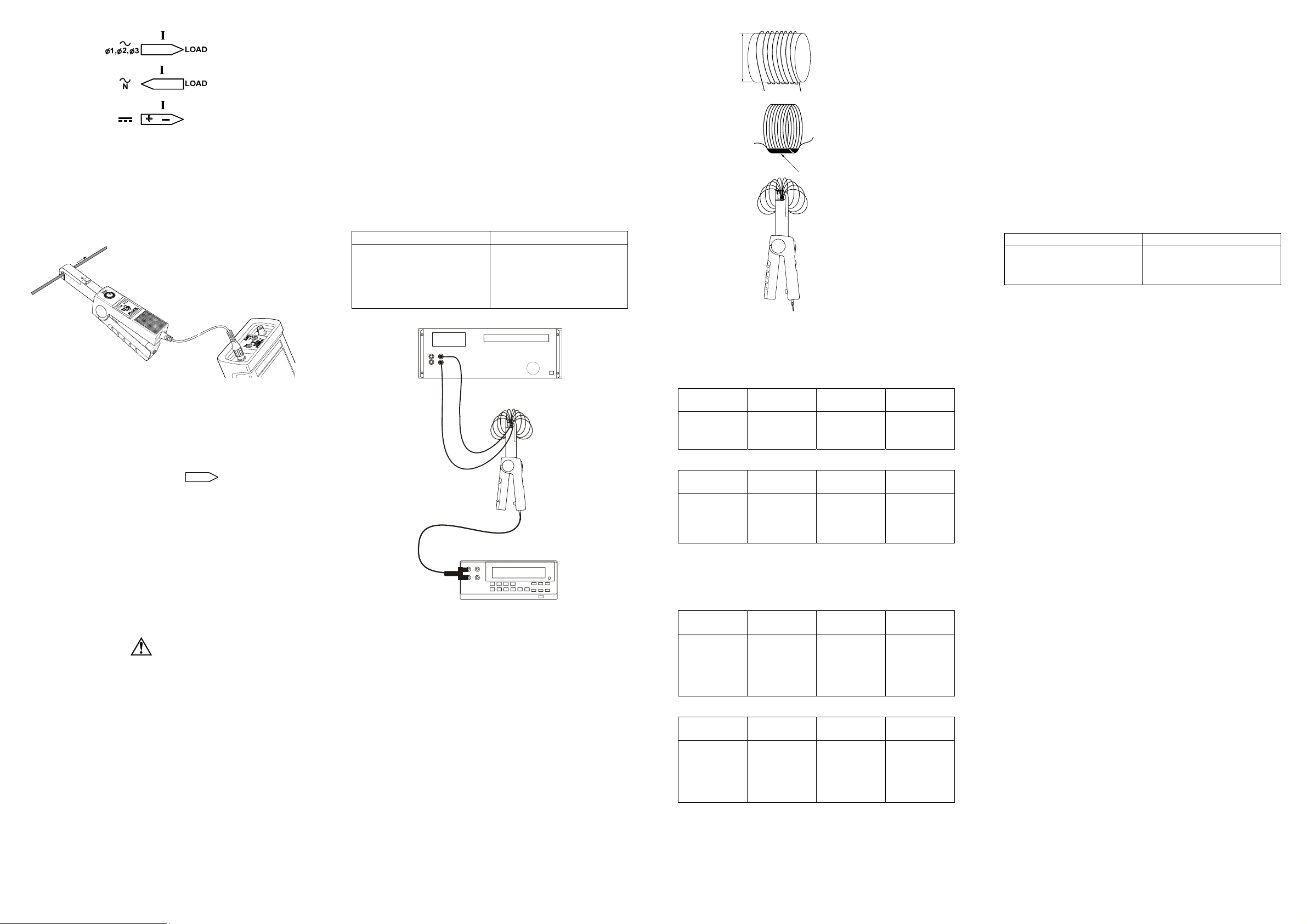
5. Clamp the Current Probe around the conductor; be sure that
the arrow marked on the jaw of the Current Probe points
toward the correct orientation. (see Figure 3.)
ST770
6
S
G
Figure 3. Orientation of the Current Probe
6. Observe the current value or waveform on your display or the
current value readout on the multimeter.
7. On the ScopeMeter test tool, adjust the vertical range knob
and time division knob for the best display.
8. If the red OL-indicator lights, the Current Probe is in overload
mode.
9. At completion, be sure to set the range selection switch to OFF
again. A measuring setup using the Current Probe and a
ScopeMeter test tool is shown in Figure 4.
A
X
X
.
X
T7704
Figure 4. Measuring Setup
Measurement considerations
Observe the following guidelines for positioning the Current Probe
Jaws:
• Center the conductor inside the probe jaws.
• Make sure the probe is perpendicular to the conductor.
• Make sure that the arrow marked
on the jaw of the
Current Probe points toward the correct direction.
Observe the following guidelines when making measurements:
• If possible, avoid measurements close to other current-
carrying conductors.
• On the Current Probe, the 100 mV/A range offers the best
accuracy.
Maintenance
Before each use, assure continued safety by inspecting the probe.
Look for cracks or missing portions of the probe housing and output
cable insulating cover and for loose or weakened components. Pay
particular attention to the insulation surrounding the probe jaws. If a
probe fails this inspection, tape it shut to prevent unintended
operation. To check probe performance, complete the "Performance
Verification" procedure.
Warning
These servicing instructions are for use by qualified
personnel only. To avoid electric shock, do not
perform any servicing procedures unless you are
qualified to do so. Read the information titled "Safety
Information" at the beginning of this instruction sheet
before proceeding.
Repairs or servicing not covered in this Users Manual should be
performed only at a Fluke Service Center. A probe under warranty
will be promptly repaired or replaced (at Fluke's discretion) and
returned at no charge.
Cleaning and storage
Periodically wipe the case with a damp cloth and detergent; do not
use abrasives or solvents. Open the jaws and wipe the magnetic
pole pieces with a lightly oiled cloth. Do not allow rust or corrosion
to form on the magnetic core ends. If the probe is not used for
periods of longer than 60 days, the battery should be removed and
stored separately.
Performance verification
Verify probe accuracy with the test setup shown in Figure 5.
Required test equipment is defined in Table 1. Toroid coil
construction is illustrated in Figure 6.
Do the following to verify the probe accuracy:
1. Set up Connection.
2. Make the checks called for in Table 2 (100 mV/A).
3. Make the checks called for in Table 3 (10 mV/A).
REQUIRED RECOMMENDED MODEL
AC/DC Calibrator
Digital Multimeter (DMM)
Small insulated screwdriver
Banana-to-BNC Adapter
10-Turn Toroid Coil
Table 1. Required Test Equipment
Fluke Model 5520A
Fluke Model 45
Spectrol
Fluke Model PM9081/001
(see Figure 6.)
5520A
10.5CM
(4 INCH)
10 TURNS WOUND ON
CYLINDRICAL FORM USING
10-GAUGE MAGNET WIRE.
REMOVE FORM AND TAPE
COIL TOGETHER MAKING
SURE 10 WIRES ARE TAPED.
TAPE
FAN OUT COIL TO APPROX. 270°
WITH SPACING 5 CM (2 INCH) USIN
TAPE TO MAINTAIN COIL SHAPE.
ST7683E
Figure 6. Toroid Coil Construction
If Your Current Probe Does Not Work
If the 80i-110s does not perform properly, use the following steps to
help isolate the problem:
1. Test the battery: be sure that the green ON-indicator lights
when you select the 10 mV/A range or the 100 mV/A range.
2. Inspect the jaw mating surface for cleanliness. If any foreign
material is present, the jaws will not close properly and errors
will result.
3. Verify that the probe is zeroed properly. For zeroing be sure
that the ScopeMeter test tool or oscilloscope is DC-coupled.
4. Verify that the function selection on the ScopeMeter test tool or
oscilloscope is correct, i.e., the display vertical resolution is not
too low or too high.
Replacement Parts
To order replacement parts in the USA, call 1-800-526-4731. To
order outside the USA, contact the nearest Service Center. Use the
following part numbers:
Description Part Number
9 Volt Battery (IEC 6LR61)
Battery Cover
Instruction Sheet
Order Fluke Part PM9081/001 BNC-to-Banana Adapter to use the
Current Probe with a digital multimeter.
4822 138 10116
5322 447 92322
4822 872 30777
LIMITED WARRANTY & LIMITATION OF LIABILITY
Table 2. Performance Test Points
Current range 0 to 10A (100 mV/A)
DC Measurement:
5520A
SETTINGS
0.1A
0.5A
0.9A
DC AMPS
MEASURED
1A
5A
9A
LOW LIMIT
OUTPUT
92 mV
480 mV
868 mV
HIGH LIMIT
OUTPUT
108 mV
520 mV
932 mV
AC Measurement:
DMM
5520A
SETTINGS
0.1A, 60 Hz
0.3A, 400 Hz
0.5A, 2 kHz
0.6A, 4 kHz
RMS AMPS
MEASURED
1A
3A
5A
6A
LOW LIMIT
OUTPUT
92 mV
286 mV
465 mV
559 mV
HIGH LIMIT
OUTPUT
108 mV
314 mV
535 mV
641 mV
Table 3. Performance Test Points
Current Range 0 to 100A (10 mV/A)
CAL5520A_45
Figure 5. Performance Test and Calibration Setup
DC Measurement:
5520A
SETTINGS
1A
3A
5A
7A
9A
DC AMPS
MEASURED
10A
30A
50A
70A
90A
LOW LIMIT
OUTPUT
95.5 mV
287.5 mV
439.5 mV
615.5 mV
765.0 mV
HIGH LIMIT
OUTPUT
104.5 mV
312.5 mV
560.5 mV
784.5 mV
1035.0 mV
AC Measurement:
5520A
SETTINGS
1A, 5 kHz
2A, 1 kHz
3A, 400 Hz
5A, 400 Hz
7A, 60 Hz
RMS AMPS
MEASURED
10A
20A
30A
50A
70A
LOW LIMIT
OUTPUT
92.5 mV
185.5 mV
287.5 mV
439.5 mV
595.0 mV
HIGH LIMIT
OUTPUT
107.5 mV
214.5 mV
312.5 mV
560.5 mV
805.0 mV
This Fluke product will be free from defects in material and
workmanship for one year from the date of purchase. This warranty
does not cover fuses, disposable batteries or damage from
accident, neglect, misuse or abnormal conditions of operation or
handling. Resellers are not authorized to extend any other warranty
on Fluke’s behalf. To obtain service during the warranty period,
send your defective product to the nearest Fluke Authorized Service
Center with a description of the problem.
THIS WARRANTY IS YOUR ONLY REMEDY. NO OTHER
WARRANTIES, SUCH AS FITNESS FOR A PARTICULAR
PURPOSE, ARE EXPRESSED OR IMPLIED. FLUKE IS NOT
LIABLE FOR ANY SPECIAL, INDIRECT, INCIDENTAL OR
CONSEQUENTIAL DAMAGES OR LOSSES, ARISING FROM ANY
CAUSE OR THEORY.
Since some states or countries do not allow the exclusion or
limitation of an implied warranty or of incidental or consequential
damages, this limitation of liability may not apply to you.
Fluke Corporation Fluke Industrial B.V.
P.O. Box 9090 P.O. Box 90
Everett WA 7600 AB Almelo
98206-9090, USA The Netherlands
SERVICE CENTERS
To locate an authorized service center,
visit us on the World Wide Web:
http://www.fluke.com
or call Fluke using any of the phone numbers listed below:
+1-888-993-5853 in U.S.A. and Canada
+31-40-267-5200 in Europe
+1-425-446-5500 from other countries
 Loading...