

Page 1

Victoreen® 8000
NERO® mAx
Users Manual
December 2006
Manual No. 8000-100-1 Rev. 9
©2006 Fluke Corporation, All rights reserved. Printed in U.S.A.
All product names are trademarks of their respective companies
Page 2

Fluke Biomedical
Radiation Management Services
6045 Cochran Road
Cleveland, Ohio 44139
440.498.2564
www.flukebiomedical.com/rms
Page 3

Table of Contents
Section 1: General Information................................................................................... 1-1
1.1 Product Description ..................................................................................... 1-1
1.2 New Features of Firmware 2.3..................................................................... 1-3
1.3 Specifications............................................................................................... 1-4
1.4 Battery Operation and Charging.................................................................. 1-5
1.5 Printing......................................................................................................... 1-6
1.6 Scope Output............................................................................................... 1-6
1.7 Procedures, Warnings, and Cautions .......................................................... 1-7
1.8 Receiving Inspection.................................................................................... 1-8
1.9 Storage........................................................................................................ 1-8
Section 2: Operation.................................................................................................... 2-1
2.1 Description................................................................................................... 2-1
2.2 General........................................................................................................ 2-1
2.3 Using the NERO mAx.................................................................................. 2-5
2.3.1 LCD Backlight Control............................................................................ 2-6
2.3.2 Measured Quantities .............................................................................. 2-7
2.4 Quick Start................................................................................................... 2-9
2.5 Modes of Operation ................................................................................... 2-10
2.5.1 Radio Mode.......................................................................................... 2-12
2.5.2 Mammo Mode ...................................................................................... 2-17
2.5.3 Fluoro Mode......................................................................................... 2-20
2.5.4 AMSE Mode......................................................................................... 2-25
2.5.5 CT Exposure Mode............................................................................... 2-28
2.5.6 Exp Mode............................................................................................. 2-30
2.5.7 HVL Mode ............................................................................................ 2-32
2.5.8 Cal Mode..............................................................................................2-43
2.5.9 Setup Mode.......................................................................................... 2-44
2.5.10 Unit ID .................................................................................................. 2-46
Section 3: Calibration.................................................................................................. 3-1
3.1 General........................................................................................................ 3-1
3.2 Calibration Check ........................................................................................ 3-1
i
Page 4

Section 4: Troubleshooting ........................................................................................ 4-1
4.1 General........................................................................................................ 4-1
4.2 Modes of Operation ..................................................................................... 4-2
4.2.1 Radio Mode............................................................................................ 4-2
4.2.2 Mammo Mode ........................................................................................ 4-5
4.2.3 Fluoro Mode ........................................................................................... 4-5
4.2.4 AMSE Mode........................................................................................... 4-6
4.2.5 Exposure Mode & CT Exposure Mode................................................... 4-6
4.2.6 HVL Mode .............................................................................................. 4-6
4.3 Error Messages ...........................................................................................4-7
4.4 Power Up Diagnostic Messages................................................................ 4-11
4.5 Waveforms - Overshoot............................................................................. 4-12
4.6 Waveforms - Partial kV Waveforms........................................................... 4-14
4.7 Waveforms - Self Rectified ........................................................................ 4-16
4.8 Waveforms - Dental with Filament Preheat................................................ 4-16
Section 5: Maintenance............................................................................................... 5-1
5.1 Fuse Replacement....................................................................................... 5-1
5.2 Battery Replacement ................................................................................... 5-1
5.3 Routine Cleaning......................................................................................... 5-2
Appendix A: Temperature and Pressure .......................................................................A-1
A.1 Temperature and Pressure..........................................................................A-1
Appendix B: mA Limits vs. kV........................................................................................B-1
B.1 mA Limits vs. kV..........................................................................................B-1
Appendix C: Exposure and Rate Resolution and Limits..............................................C-1
C.1 Exposure and Rate Resolution and Limits...................................................C-1
Appendix D: CT Exposure Resolution...........................................................................D-1
D.1 CT Exposure Resolution..............................................................................D-1
Appendix E: Ion Chamber of Sensitive Volume............................................................E-1
E.1 Ion Chamber of Sensitive Volume ...............................................................E-1
Appendix F:
Replacement Parts .................................................................................... F-1
F.1 Replacement Parts......................................................................................F-1
F.2 Accessories ................................................................................................. F-2
ii
Page 5

General Information
Product Description
1
Section 1
General Information
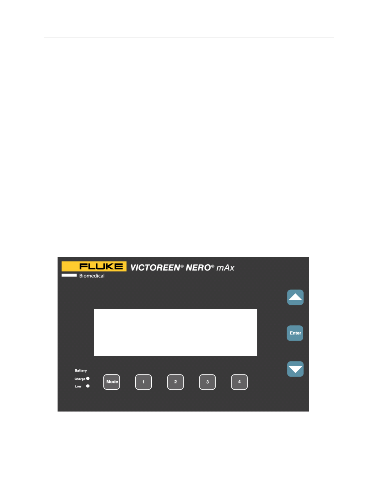
1.1 Product Description
To proceed directly to "Quick Start", go to Section
2.4.
To proceed directly to "Setup Mode", go to Section
2.5.9.
The Victoreen NERO™ mAx Model 8000, Non-invasive Evaluator of Radiation Output, uses an
innovative system of menus and softkeys to provide an intuitive, user friendly operating environment. All
measurement modes and options are displayed on the NERO mAx’s LCD and all functions are controlled
by the 5 softkeys beneath the display and the 3 keys to the right of the display.
NOTE
The NERO mAx consists of the NERO mAx control console, detector, detector cable, filter slides, AC
adapter, HVL plates, manual, Microsoft® Excel Add-in and carrying case.
The NERO mAx control console is compact and easy to use. The sophisticated electronics necessary to
provide highly accurate, reproducible measurements while maintaining an intuitive, user friendly operating
system are in the NERO mAx control console. The NERO mAx’s rechargeable battery is also housed in
the control console. The front panel of the control console contains a backlit 240 x 64 pixel, dot matrix
LCD display and eight push buttons. Connectors for power input, RS-232, printer, scope output and the
NERO mAx detector are located on the control console’s rear panel.
1-1
Page 6
Victoreen 8000
Operators Manual
Figure 1-1.Control Console Front Panel
Figure 1-2. Control Console Rear Panel
The NERO mAx detector contains sensors for simultaneously measuring kV, exposure or rate and
invasive mA or mAs. Solid-state detectors are used to measure kV. An ion chamber, located in the top
of the detector, is used for exposure/rate measurements. In addition, connectors for an external ion
chamber are provided on the rear panel of the 8000 detector. The NERO mAx detector’s interface
connector is also located on the detector’s rear panel. The front panel has a keyed opening for the model
8000-filter slides and a connector for mAs leads.
1-2
Page 7
General Information
Product Description
The NERO mAx filter cards contain the various filters needed to accurately measure kilovoltage. Each
filter card is coded so that the NERO mAx “knows” which filter is in use and its position. The NERO mAx
also verifies that the filter card is valid for the selected measurement mode. In addition, the filter cards
are keyed so that they may only be inserted one way. The W/Al filter card is labeled with the kVp ranges
for which it is calibrated. The Mammo filter card is labeled for the x-ray tube targets for which it is
calibrated.
The serial numbers of the NERO mAx control console unit, detector and filter cards must be matched in
order to obtain accurate results. Since the control console unit, detector and filter cards are calibrated
together, they
must be used together for accurate measurements.
1
1.2 New Features of Firmware Release 2.3
This release adds several new features to the Radiographic mode that give the NERO mAx greater
flexibility when making kV and exposure time measurements on all types of radiographic and dental x-ray
machines.
1. The %kV setting provides more time measurement options:
• Time measurements from 90%, 80%, and 75% of the peak kV.
• Pulse counting and zero crossing settings for single-phase generator time measurements.
2. User settable measurement delay allows:
• kV overshoot portion of waveform to be excluded from kV analysis.
• Exclusion of x-ray generator preheat pulses from kV and time analysis.
More information on these new features may be found in “Using a Measurement Delay” and “Using %kV
and Exposure Time Measurements” at the end of Section 2.5.1--Radio Mode.
1-3
Page 8

Victoreen 8000
Operators Manual
1.3 Specifications
Kilovoltage
Measured during the first 480 ms of exposure
Accuracy: 0.5 kV or ± 1%
Reproducibility: 0.5 kV or ± 1%
Range: W/Al 30 - 60 kV
50 - 100 kV
80 - 160 kV
Mo/Mo 22 - 35 kV
Mo/Rh 22 - 40 kV
Mo/Al 22 - 49 kV
Rh/Rh 25 - 49 kV
Rh/Al 25 - 49 kV
Time To Display
Radio & Mammo: 3 seconds for 0.1 second exposure
1 second for each 32 ms of exposure time
Fluoro & AMSE: 15 seconds for all exposures
Time
Measured during entire exposure at 90% rise/fall of waveform.
Accuracy: 1 ms
Range: 1 ms to 60 sec
Exposure/Exposure & Rate
Measured during entire exposure; kVp corrected.
Accuracy: ± 5%
Reproducibility: (Radio & Mammo Modes) ± 2% or 2 mR
Range: 1 mR minimum
mAs and mA
Measured during entire exposure
Accuracy: ± 2%
Reproducibility: ± 1% or 0.2 mAs
Range: 1 - 1000 mA
HVL
Accuracy: ± 5%
Range: .1 - 99.9 mmAl
Physical
Display: 240 x 60 pixel, super twist LCD w/ccfl backlight
Power: 115 or 230 VAC External Supply. Rechargeable internal batteries supply more than
4 hours of continuous service with overnight charge.
1-4
Page 9

Size:
Console: 9.00" x 9.12" x 3.25" (22.86 mm x 23.17 mm x 8.26 mm)
Detector: 6.56" x 3.70" x 2.58" (16.66 mm x 9.4 mm x 6.55 mm)
Slides Only: 2.4" x 6.25" x 0.31" (6.1 mm x 15.88 x 0.8 mm)
Operating Conditions:
10° C to 40°C (50° F to 104° F)
Maximum 90% relative humidity (non-condensing)
Weight:
Console: 4 lbs. 9.0 oz. (2.067 kg)
Detector: 1 lb. 10.4 oz. (with slide) (.747 kg)
Slides Only: 2.9 oz. & 3.2 oz. (.090 kg & .094 kg)
HVL Set
2.30 mm, 1.0 mm, 0.3 mm
Calibration
W/Al calibrated with 4.5 millimeters of Aluminum total filtration
Mo/Mo calibrated with 30 microns of Molybdenum filtration
Mo/Rh calibrated with 25 microns of Rhodium filtration
Mo/Al calibrated with 1 millimeter of Aluminum filtration
Rh/Rh calibrated with 25 microns of Rhodium filtration
Rh/Al calibrated with 1 millimeter of Aluminum filtration
General Information
Specifications
1
1.4 Battery Operation and Charging
The NERO mAx has an internal rechargeable battery which provides up to four hours of continuous
operation depending upon usage. The NERO mAx draws twice as much power from its from its battery
when it is actively making measurements than it does when in an idle state with its backlight off. To
conserve and extend battery life, the NERO mAx incorporates several power saving features. The
display backlight automatically turns off after one minute of inactivity. The backlight turns on when any
key is pressed or an exposure is made while in any measurement mode. In addition, the NERO mAx
exits from any measurement mode after five minutes of no activity. Pressing the ENTER key restores the
NERO mAx to its previous measurement mode.
The NERO mAx utilizes two levels of protection to assure reliable operation when the battery charge
becomes low. The first level of protection is a warning that is displayed when there is approximately 20
minutes of battery life remaining. During this time, the AC adapter may be plugged into the NERO mAx to
continue operation without interruption. The second level occurs when the battery charge is insufficient to
guarantee proper operation. When this occurs, the low battery indicator in the lower left corner of the
front panel illuminates and the instrument shuts down, becoming inoperable. When this happens, the AC
adapter can be plugged into the NERO mAx to restore operation. The NERO mAx “remembers” what
mode it was in before it shut down and returns to that mode upon power up. Pressing the ENTER key
returns the NERO mAx to its measurement mode.
The battery is charged whenever the NERO mAx is connected to its AC adapter and the adapter is
plugged into a suitable power source. When the power switch is on, the battery is charged at a low rate
that is enough to sustain the battery’s charge. When the power switch is off, the battery is charged at a
high rate.
To fully charge the battery, make sure that the NERO mAx is turned OFF, plug the AC adapter into the
rear of the NERO mAx console and plug the adapter into a suitable power source. The green battery
1-5
Page 10
Victoreen 8000
Operators Manual
charge indicator on the front panel of the NERO mAx console illuminates when the battery is charging.
When the battery charge indicator is off, the battery is charged. It may take up to 16 hours to fully
recharge a severely discharged battery.
1.5 Printing
All of the exposure results displayed by the NERO mAx may be printed automatically if desired. The
data that is sent to the printer includes the NERO mAx’s mode of operation and selected options, the
current time and date, and the measured data. The NERO mAx uses a standard IBM compatible PC
printer cable.
With the NERO mAx turned off, plug the computer end of a standard IBM compatible PC printer cable into
the printer port at the rear of the NERO mAx then plug the printer end of the cable into the printer and turn
the printer on. Plug the AC adapter into the 8000 if needed (see Section 1.4--Battery Operation and
Charging) and turn the instrument on. From the readout menu, select setup screen and turn the
automatic printing on as follows:
SETUP CLOCK − > OFF
CAL PRINT − > ON
HVL UNITS − > R
EXP AIR −−− > 20.5 C 734 mmHg
CT EXP DATE −−> Oct. 10, 1996
AMSE TIME −−> 10 30 45
MODE SELECT ON/OFF
From the SETUP screen, use the SELECT softkey (under column 1) to select PRINT. When PRINT is
selected, the print selection blinks and a highlight (reverse video) extends across the other display field.
Press the ON/OFF softkey (under column 2) to turn automatic printing to ON. Now, whenever a
measurement is made, all of the measured results that are displayed on the NERO mAx’s screen will also
be sent to the printer.
If the printer is off line, out of paper or is otherwise non functional, the NERO mAx will display a printer
error message and printing will be disabled. If the printer becomes functional and returns to an on line
status with no errors, the NERO mAx will resume printing with the next exposure.
To turn automatic printing off, follow the procedure outlined above and toggle PRINT to OFF.
1.6 Scope Output
The NERO mAx scope output provides a real time output of the radiation waveform from the NERO mAx
detector. This output is from the less filtered detector; “channel A”. This signal can have a maximum
amplitude of approximately 5 volts. This signal is always available at the scope output BNC connector.
The NERO mAx does not need to be in a kVp measurement mode to provide a real time scope output,
but the NERO mAx detector must be in the beam.
To use the real time scope output, connect the NERO mAx’s scope output to an oscilloscope input using
a suitable BNC cable. Set the oscilloscope horizontal deflection controls to the desired sweep period and
adjust the scope to trigger on a positive slope. Some experimentation will be necessary to get the trigger
level and the vertical deflection adjusted properly. Generally, exposures made at the top of the selected
kV range will have signals above one volt and exposures made near the bottom of the selected kV range
will have signals in the tens of millivolts.
1-6
Page 11
General Information
Procedures, Warnings, and Cautions
1
1.7 Procedures, Warnings, and Cautions
The equipment described in this manual is intended to be used for the detection and measurement of
ionizing radiation. It should be used only by persons who have been trained in the proper interpretation of
its readings and the appropriate safety procedures to be followed in the presence of radiation.
Although the equipment described in this manual is designed and manufactured in compliance with all
applicable safety standards, certain hazards are inherent in the use of electronic and radiometric
equipment.
WARNINGS and CAUTIONS are presented throughout this document to alert the user to potentially
hazardous situations. A WARNING is a precautionary message preceding an operation that has the
potential to cause personal injury or death. A CAUTION is a precautionary message preceding an
operation that has the potential to cause permanent damage to the equipment and/or loss of data.
Failure to comply with WARNINGS and CAUTIONS is at the user’s own risk and is sufficient cause to
terminate the warranty agreement between Fluke Biomedical and the customer.
Adequate warnings are included in this manual and on the product itself to cover hazards that may be
encountered in normal use and servicing of this equipment. No other procedures are warranted by Fluke
Biomedical. It shall be the owner’s or user’s responsibility to see to it that the procedures described here
are meticulously followed, and especially that WARNINGS and CAUTIONS are heeded. Failure on the
part of the owner or user in any way to follow the prescribed procedures shall absolve Fluke Biomedical
and its agents from any resulting liability.
Indicated battery and other operational tests must be performed prior to each use to assure that the
instrument is functioning properly. If applicable, failure to conduct periodic performance tests in
accordance with ANSI N323-1978 (R1983) Radiation Protection Instrumentation Test and
Calibration, paragraphs 4.6 and 5.4, and to keep records thereof in accordance with paragraph 4.5 of the
same standard, could result in erroneous readings or potential danger. ANSI N323-1978 becomes, by
this reference, a part of this operating procedure.
Warning Summary
The following WARNINGS are provided for your reference and may appear throughout the NERO mAx
manual:
Extreme caution should be used when making
connections to the mAs terminals of the X-ray
generator or detector. Improper connections may
result in injury, damage to the NERO mAx, and/or
damage to the x-ray generator. Tube current (mA
and mAs) measurements should only be made by
persons familiar with the calibration and repair of xray machines.
An electric shock hazard exists between the ion
chamber bias connector and ground.
WARNING
WARNING
1-7
Page 12
Victoreen 8000
Operators Manual
Caution Summary
The following CAUTIONS are provided for your reference and may appear throughout the NERO mAx
manual:
Use extreme caution when connecting to the mAs
terminal of the detector.
If line voltage surges beyond 15% of normal, a
power line conditioner must be used, otherwise
damage to the charging circuit will occur.
Note Summary
In the event of a transient induced lockup of the
Model 8000 NERO mAx, it is necessary to reset the
unit by cycling its power (turning it off then on).
After reset, the unit will power up in its normal
operating mode.
1.8 Receiving Inspection
CAUTION
CAUTION
NOTE
Upon receipt of the package:
1. Inspect the carton(s) and contents for damage. If damage is evident, file a claim with the carrier
and notify Fluke Biomedical at 440.248.9300.
2. Remove the contents from the packing material.
3. Verify that all items listed on the packing list have been received and are in good order.
1.9 Storage
If the unit is to be stored prior to use, pack it in the original container, if possible, and store in an
environment free of corrosive materials, fluctuations in temperature and humidity, and vibration and
shock.
Prior to use, check the condition and functionality of the device. Also check that the calibration is still
valid. Periodic recalibrations are usually required by individual radiation safety and/or quality assurance
programs. Please consult your local radiation safety or quality assurance office if you have any
questions.
1-8
Page 13

Operation
Description
2
Section 2
Operation
2.1 Description
The NERO mAx consists of the NERO mAx control console, detector, detector cable, filter slides, AC
adapter, HVL plates, manual, Microsoft Excel Add-in and carrying case.
The NERO mAx control console is compact and easy to use. The sophisticated electronics necessary to
provide highly accurate, reproducible measurements while maintaining an intuitive, user-friendly operating
system are contained in the NERO mAx control console. The NERO mAx’s rechargeable battery is also
housed in the control console. The front panel of the control console contains a backlit 240 x 64 pixel, dot
matrix LCD display and eight push buttons. Connectors for power input, RS-232, printer, scope output
and the NERO mAx detector are located on the control console’s rear panel. The ON/OFF switch is
located on the right side of the control console.
The NERO mAx detector contains sensors for simultaneously measuring kV, exposure or rate and
invasive mA or mAs. Solid-state detectors are used to measure kV. An ion chamber, located in the top
of the detector, is used for exposure/rate measurements. In addition, connectors for an external ion
chamber are provided on the rear panel of the 8000 detector. The NERO mAx detector’s interface
connector is also located on the detector’s rear panel. The front panel has a keyed opening for the model
8000-filter slides and a connector for mAs leads.
The NERO mAx filter cards contain the various filters needed to accurately measure kilovoltage. Each
filter card is coded so that the NERO mAx “knows” which filter is in use and its position. The NERO mAx
also verifies that the filter card is valid for the selected measurement mode. In addition, the filter cards
are keyed so that they may only be inserted one way. The W/Al filter card is labeled with the kVp ranges
that it is calibrated for. The Mammo filter card is labeled for the x-ray tube targets that it is calibrated for.
The serial numbers of the NERO mAx control console unit, detector and filter slides must be matched in
order to obtain accurate results. The control console unit, detector and filter slides are calibrated
together, and
must be used together for accurate measurements.
2.2 General
Positioning the Control Console
Position the NERO mAx control console on a stable, flat surface within 25 feet of the detector. If a printer
is to be used with the NERO mAx it should also be placed on a stable, flat surface.
Positioning the Detector
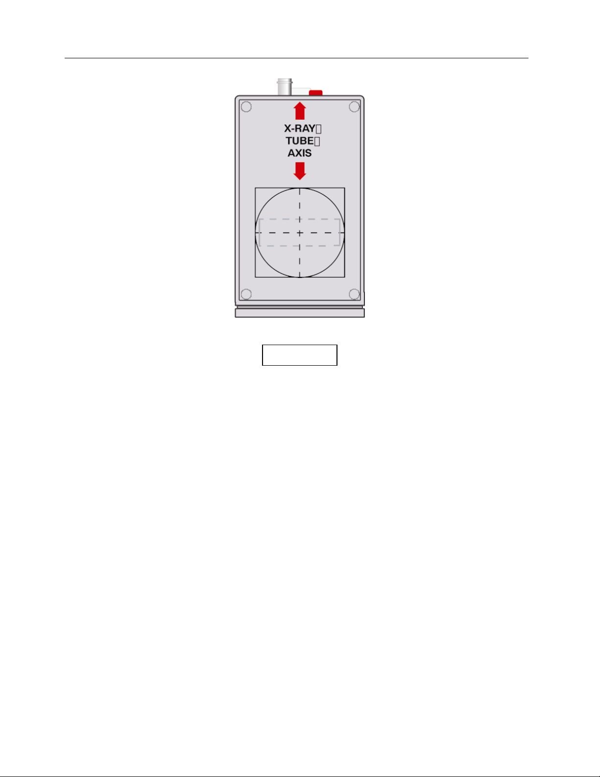
Correct and reproducible positioning of the NERO mAx detector in the x-ray beam is very important in
obtaining accurate and reproducible results from the NERO mAx. Fluke Biomedical has printed several
alignment marks on top of the detector to assure correct, reproducible positioning of the detector.
The black circle is the minimum collimated beam size required for accurate exposure, rate and kVp
measurements. This circle defines the diameter of the NERO mAx’s internal ion chamber.
2-1
Page 14
Victoreen 8000
Operators Manual
NOTE
The dashed gray rectangle is the minimum
collimated beam size required for accurate kVp
measurements only. This rectangle outlines the
NERO mAx’s kV detectors. Exposure and rate
results from an x-ray beam collimated to this area
will be incorrect because the beam is not
illuminating all of the internal ion chamber.
The black square and the dashed black crosshairs are alignment marks to aid in positioning the NERO
mAx detector in the x-ray beam.
The red arrows on the detector indicate the axis of the detector that should be aligned with the x-ray tube
axis for the most accurate measurements. This minimizes any heel effect.
Radiographic
Install the W/Al filter slide in the detector and set the filter slide to the desired kVp range. Position the
detector under the x-ray tube with the top of the detector facing up. Align the detector along the axis of
the x-ray tube to minimize heel effect. Set x-ray tube SDD (normally 26 inches) and collimate the beam
size to the round or square alignment marks on the top of the detector. Align the x-ray beam by making
the light field crosshairs coincident with the crosshairs on the top of the detector.
Dental
Set the detector on a flat, stable surface and position the x-ray tube so that the cone is just above the
detector's top surface.
2-2
Page 15
Operation
General
NOTE
2
Do not rest the cone on the detector. This may
depress the top of the ion chamber and cause
incorrect exposure measurements.
Make sure that the detector is aligned along the axis of the x-ray tube and that the tube is perpendicular
to the detector's top surface and is centered over the detector crosshairs.
Mammography
Install the Mammo filter slide in the detector and set the filter slide for the x-ray machine’s target material.
Position the detector under the x-ray tube with the top of the detector facing up. Align the detector along
the axis of the x-ray tube to minimize heel effect. Set x-ray tube SSD (normally 26 inches) and collimate
the beam size to the square alignment marks on the top of the detector. Line up the front edge of the
square alignment mark on the top of the detector with the front edge (toward the chest wall) of the
collimated x-ray beam.
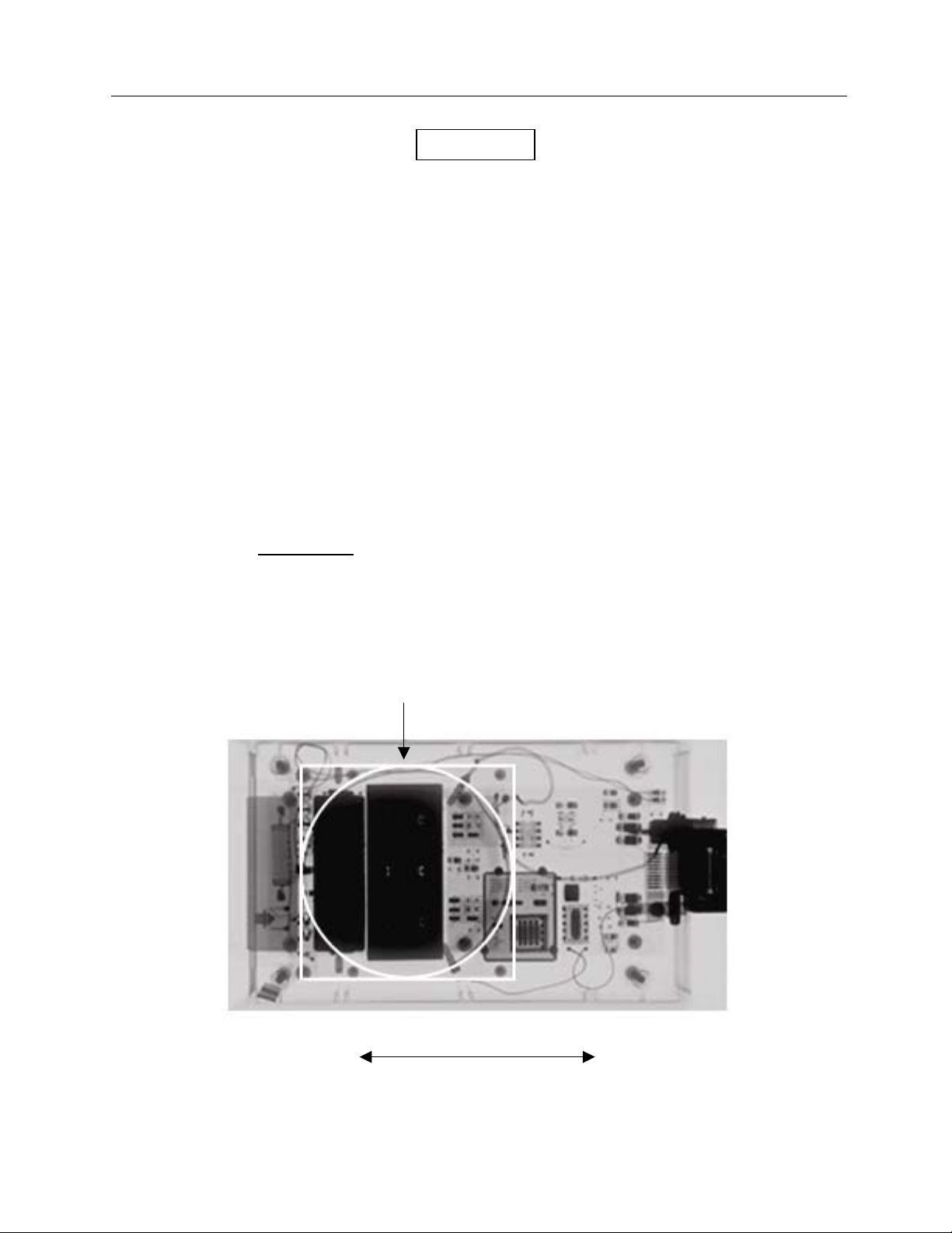
Fluoroscopy
Install the W/Al filter slide in the detector and set the filter slide to the desired kVp range. The kVp range
is the range closest to the detector front panel.
Position the detector
ray tube) and align the detector along the axis of the x-ray tube to minimize heel effect. Using the
centering marks provided on the table (or other centering methods), center the detector over the x-ray
beam. Don protective clothing and energize the fluoroscope to view the detector on the fluoro screen.
Move the fluoroscope so that the lead shield containing the NERO mAx’s detector diodes (opaque
rectangle) is centered on the screen.
upside down on the table (the top of the detector must be positioned toward the x-
Collimate to this area
X-Ray Tube Axis
Fluoro Detector Positioning
2-3
Page 16
Victoreen 8000
Operators Manual
For automatic brightness control machines, place appropriate shielding over the detector to drive the
output to its maximum. A folded lead apron, gloves or a lead sheet may be used. For manual systems,
set the machine for its maximum output and use appropriate shielding to protect the image intensifier.
Other Applications
The basic principles are the same for other applications. In general, the detector should be located 18 to
40 inches from the x-ray source. The detector should be aligned with the x-ray tube axis with the top of
the detector facing the x-ray source. The detector should be in the center of the x-ray beam and the
beam should be collimated to the round or square alignment marks on the top of the detector.
For chest x-ray machines, the detector may be strapped or taped to the table in front of the film cassette.
For panoramic dental machines, the detector may be strapped or taped to the film cassette holder.
Inserting the Filter Slide
The NERO mAx filter slides are inserted into the front of the detector. The filter slides are keyed so that
they may only be inserted one way. To insert the filter slide, place the filter slide in the opening in the
front of the detector and gently push. The slide will click into place at each of its positions. Move the filter
slide until the desired kVp range (W/Al) or target material (Mammo) is closest to the detector front panel
(below “kVp RANGE”).
Connections to the NERO mAx
The NERO mAx detector and control console are connected to each other via a 25-foot cable. The
NERO mAx power should be turned
an external ion chamber to the detector or connecting the mAs leads.
off when connecting the detector to the control console, connecting
mAs Connections
Extreme caution should be used when making
connections to the mAs terminals of the X-ray
generator. Improper connections may result in
injury, damage to the NERO mAx, and/or damage
to the x-ray generator. Tube current (mA and
mAs) measurements should only be made by
persons familiar with the calibration and repair of xray machines.
Two mAs cables are provided with the NERO mAx; 12-ft. long mAs leads and 12-ft. long mAs extension
leads. The mAs leads are black, with a miniature phone plug at one end and alligator clips at the other
end, the mAs extension leads have clear insulation with two banana plugs at one end and alligator clips
at the other end. The miniature phone jack of the black mAs leads plugs into the mAs jack on the front
panel of the NERO mAx detector. The alligator clips may then be connected to the generator’s mAs
terminals. If the black mAs leads have insufficient length, the mAs extension leads may be used to
provide additional length. The mAs extension leads may be used in two ways; the extension lead banana
jacks may be plugged into the generator’s mAs terminals (if the generator has banana jacks) or the
extension leads may be reversed and the alligator clips can be clipped to the generator’s mAs terminals.
WARNING
The opposite end of the mAs extension leads are to be connected to the alligator clips at the end of the
black mAs leads. When using the mAs extension leads, care should be used to make sure that the leads
are not shorted together when they are connected.
2-4
Page 17
Operation
General
The mAs leads should always be connected in the ground return of the high voltage transformer.
Damage to the generator or the NERO mAx or inaccurate measurements may result if the mAs leads are
connected to any point other then the ground return of the x-ray tube current. Tube current
measurements should only be made on generators providing open and short circuit protection of the
metering circuit and where the circuit operates near ground potential. The polarity of the mAs input signal
is not important because a full wave bridge is used in the NERO mAx mAs input circuit.
2
Printer Connections
When using the NERO mAx with a printer, both the printer and the NERO mAx should be turned off prior
to connection. The NERO mAx uses a standard IBM PC printer cable. For more information on printing
with the NERO mAx, see Section 1.5--Printing.
AC Adapter
The AC adapter may be plugged into the NERO mAx at any time. For more information on using the AC
adapter with the NERO mAx, see Section 1.4--Battery Operation and Charging.
Scope Output
The NERO mAx’s scope output may be connected to a suitable oscilloscope at any time. For more
information regarding the real time scope output, see Section 1.6--Scope Output.
2.3 Using The NERO mAx
The NERO mAx uses an innovative system of menus and softkeys to provide an intuitive, user-friendly
operating environment. All measurement modes and options are displayed on the NERO mAx’s LCD and
all functions are controlled by the 5 softkeys beneath the display and the 3 keys to the right of the display.
2-5
Page 18

Victoreen 8000
Operators Manual
The NERO mAx display is divided into 5 columns, each column corresponds to the push button (softkey)
directly beneath it. The left most column is the “MODE” column that is used to select the NERO mAx’s
operating mode. The remaining four columns (1 through 4) display various options for each mode.
A highlight (reverse video block) denotes the selected menu element in each column. A blinking highlight
(reverse video block) locates the “active” menu column and highlights the selected menu element in that
column.
Legends, which describe the function of each softkey, appear along the bottom of the display. These
legends are separated from the rest of the display by a horizontal line. The time and date may be
displayed in the upper right corner of the display.
There are eight push buttons on the front panel of the NERO mAx. The five buttons directly beneath the
display are “softkeys”, their functions change according to the NERO mAx’s mode of operation. These
softkeys are used to select the NERO mAx’s mode of operation and various options within each mode.
These softkeys are also used to increment numerical values such as time or date. The “MODE” softkey
has two functions. First, it may be used to select the NERO mAx’s operating mode. Second, it may be
used to exit from any active measurement mode.
The “UP” and “DOWN” keys to the right of the display are also used to select the NERO mAx’s mode of
operation and various options within each mode. The “UP” and “DOWN” buttons move the highlight up
and down within each selected column to select various options. When the “UP” button is pressed, the
highlight moves up one menu element and wraps around when it reaches the top of the column and
returns to the bottom. When the “DOWN” button is pressed, the highlight moves down one menu element
and wraps around when it reaches the bottom. If only two options are available, the highlight toggles
between the two selections. In the calibration and setup modes, the “UP” and “DOWN” buttons are used
to toggle between options or to increment and decrement numeric values.
The “ENTER” button to the right of the display is used to initiate data acquisition and measurement with
options that have been selected. It also is used to accept numeric data in situations requiring data entry.
Each of the NERO mAx’s operating modes has a menu. All available menu options for each mode are
displayed in columns 1 through 4 above each softkey. All menus are left justified. This means that
changes made in columns on the left (such as the MODE column) may affect the columns of options to
the right. Softkey legends appear along the bottom of the display and as the menu options change, the
softkey legends change. The left most menu column is the ‘mode’ column, which displays the available
operating modes. The legend above the “MODE” softkey never changes, as this key always selects the
mode of operation of the NERO mAx.
Pressing the softkey under any column (MODE, 1 - 4) moves the blinking highlight into that menu column,
thereby selecting that column, and moves the highlight up through the available options. The highlight
wraps around when it reaches the top of the column and returns to the bottom. If only two options are
available, the highlight toggles between the two selections. In the calibration and setup modes, some of
the softkeys are used to toggle between options or to increment numeric values.
To make a measurement with the NERO mAx, simply highlight the desired measurement mode and
options and press the enter button. For more information on a specific measurement mode, see the
manual section that applies to that mode or x-ray generator type.
All of the NERO mAx’s operating modes are described in "Modes of Operation", following "Quick Start".
2.3.1 LCD Backlight Control
As a power saving feature, the NERO mAx LCD backlight turns off after one minute of no activity. The
backlight turns back on when any button is pressed. When the NERO mAx backlight turns off while
exposure results are being displayed, the backlight may be restored without affecting the displayed
exposure results by pressing any key except the MODE key. Pressing the mode key exits from the active
measurement mode and returns to the menu screen, erasing all exposure data.
2-6
Page 19

Operation
Using the NERO mAx
2
2.3.2 Measured Quantities
kV
The NERO mAx calculates kVp from the ratio between two differentially filtered detector channels (A&B).
When an x-ray exposure is made, the NERO mAx samples the two detector channels simultaneously at a
rate of 100,000 samples per second. The detector waveforms are digitized by a pair of 100 kHz 16 bit
A/D converters and stored in memory.
The NERO mAx has sufficient memory to store up to 480 milliseconds of waveform data. For
radiographic exposures that exceed 480 milliseconds in length, the NERO mAx stores the first 320
milliseconds of the waveform and the last 160 milliseconds. This method allows storage of both the rising
and falling edges of the x-ray waveform. In the fluoro and AMSE modes, the NERO mAx stores a 480millisecond sample of the x-ray waveform after the SAVE key is pressed.
A delay of up to 999 milliseconds may be used to delay the start of kV data acquisition in the Radio and
Mammo modes. This delay may be used to skip events that occur at the beginning of an exposure, such
as an overshoot or undershoot. When a delay is used, only the kV data acquisition is effected.
Exposure, mAs and time measurements are not delayed and are measured over the entire exposure.
After the exposure is complete, the NERO mAx searches the stored channel A and B waveforms for ratio
peaks, when a peak is found it is stored. These peaks are then averaged and the average kVp is
calculated. While the NERO mAx searches for ratio peaks, it also looks for the highest peak, when the
highest peak is found it is stored and peak kV is calculated. Effective kV is calculated from the ratio of the
integrated A and B waveforms which is analogous to the density ratio in the kVp film cassette.
When calculating kVp average in the radiographic mode, the NERO mAx only includes peaks that are
above the selected %kV in its kVp average calculation. When ZERO or 1ØPULSE are selected, the
NERO mAx includes all detected peaks in the kVp average calculation.
The NERO mAx calculates kV as a function (F) of the ratio between the two detector channels, A and B
(r). The calculations used to calculate kV peak, kV effective and kVp average are summarized below:
kVp Average = F (r), where r is the average peak ratio B/A
kV Peak = F (r), where r is the peak ratio B/A
kV Effective = F (r), where r is the ratio
The calibration information that the NERO mAx uses to calculate kV is stored in nonvolatile memory in the
NERO mAx control console.
∑
B/A
∑
Time
The NERO mAx measures exposure time by determining the time between the first and last passage
through a preset percentage of kVp average. To accomplish this, the NERO mAx calculates the detector
ratio that corresponds to the preset percentage of the exposure's kVp, then measures the time between
those points on the rising and falling edges of the ratio waveform. In the Radiographic mode, the
percentage of kVp average over which the NERO mAx measures radiographic exposure time may be
selected using the %kV key. In the Mammographic mode, the percentage is fixed at 90% of kVp
average.
In the radiographic mode, when 75%, 80%, or 90% kV is selected, the NERO mAx measures exposure
time between the 75%, 80%, or 90% points on the kV waveform. When zero crossing (ZERO) is
selected, the NERO mAx measures radiographic exposure time from the moment x-rays are detected
until they are no longer detected. When 1ØPULSE is selected, the NERO mAx counts the number of xray pulses in a pulsed or single-phase radiographic exposure. This is primarily for use with single phase
full and half wave rectified generators.
In pulsed and single-phase applications when time is measured in pulses (1ØPULSE), use of a
measurement delay may introduce errors in the pulse count because the NERO mAx does not count
pulses during the delay time. In pulsed and single-phase applications when time is measured at a
2-7
Page 20

Victoreen 8000
Operators Manual
percentage of kV, use of a measurement delay can also introduce errors. If the delay terminates between
pulses, when no x-rays are present, the NERO mAx waits until the beginning of the next pulse to begin
timing. If the delay terminates during a pulse, when x-rays are present, the NERO mAx begins timing
immediately.
When a delay is used in making measurements in the Radio and Mammo Modes, the NERO mAx
calculates exposure time differently. If a positive measurement delay is used in making a measurement,
the NERO mAx includes the delay time in its calculated exposure time. In addition, the exposure time
may be slightly longer than the exposure time between the selected %kV points on the kV waveform.
This is because the Model 8000 does not store the leading edge of the x-ray output waveform; it waits for
the specified delay time before acquiring kVp data. Because of this, the %kV point on the rising edge of
the kV waveform is not stored and the rise time of the waveform appears to be instantaneous. The
difference between the actual and measured exposure times is the rise time between zero and the
specified %kV. When a negative measurement delay is specified, the NERO mAx does not include the
delay time in the measured exposure time. The measured exposure time is from the beginning of data
acquisition or the %kV point on the first rising edge after the delay until passage through the %kV point on
the falling edge of the kV waveform.
More information on using the %kV function or using a measurement delay may be found at the end of
the Radio Mode section under "Using %kV and Exposure Time Measurements" or "Using a Measurement
Delay".
Exposure and Exposure Rate
The NERO mAx measures exposure by integrating the signal from an ion chamber (either internal or
external) and applying the proper conversion factor(s) to calculate exposure (R or Gy). Exposure rate is
calculated by sampling the integrated charge from the ion chamber at one-second intervals and dividing
the integrated charge by the sample period and applying the proper conversion factor(s). In the Pulsed
Fluoro and AMSE modes, the NERO mAx calculates exposure per pulse or frame by sampling the
integrated charge from the ion chamber at one second intervals and dividing by the number of pulses or
frames that it counts in a one second interval and applying the proper conversion factor(s). The NERO
mAx's ion chamber is internally vented and all exposure and rate measurements are corrected for air
density based upon user entered temperature and pressure.
The NERO mAx’s internal ion chamber is factory calibrated to provide accurate exposure and rate
measurements over the entire kVp range of the NERO mAx. These exposure and rate measurements
are adjusted by applying energy dependent correction factors that are determined by comparison to
applicable N.I.S.T. techniques.
In addition to the factory calibration, a user entered multiplier is available for exposure and rate
measurements made with the NERO mAx’s internal ion chamber.
When using external ion chambers, exposure and rate are calculated using the user entered calibration
factor (R/nC or Gy/nC) for the selected chamber. When making measurements in the CT Exposure mode
with a CT chamber, user entered beam width is also used in calculating exposure and rate.
mAs and mA
The NERO mAx measures mAs by integrating the signal from the mAs input during an x-ray exposure.
To calculate mA, the integrated signal from the mAs input is sampled at one-second intervals and divided
by the sample period. In the Pulsed Fluoro and AMSE modes, the NERO mAx calculates mAs per pulse
or frame by sampling the integrated signal from the mAs input at one second intervals and dividing by the
number of pulses or frames that it counts in a one second interval. The mA(s) circuitry is factory
calibrated using a calibrated current source and is not user adjustable.
HVL
In the HVL mode, the NERO mAx calculates half value layer based upon a series of exposure or rate
measurements made with varying thicknesses of aluminum absorbers placed in the x-ray beam. The
exposure or rate measurements may be made using the NERO mAx’s internal ion chamber or an external
2-8
Page 21
Operation
Using the NERO mAx
ion chamber. HVL is calculated using a linear regression of the natural log of the normalized exposure
versus absorber thickness in millimeters of aluminum. Below is the formula used by the NERO mAx to
calculate half value layer.
()
BxAHVL +∗= ln
Where: x = Normalized dose at Half Value Layer (0.5)
A = Slope of ln(x) vs. mmAl
B = Intercept of ln(x) vs. mmAl (Usually very close to zero)
2.4 Quick Start
Locate a suitable radiographic x-ray generator. Set the generator for approximately 80 kV, 100 mA, .1
seconds or 10 mAs.
2
CAUTION
Make sure the NERO mAx is turned off.
Plug the detector cable into the back of the NERO mAx at the connector marked DETECTOR.
Plug the other end of the detector cable into the NERO mAx detector.
Insert the W/Al filter slide into the front filter slot of the NERO mAx detector at the 50 - 100 kVp position.
The filter slide will click into place.
Place the detector on the x-ray table at approximately 26” SDD. Make sure that the top of the detector is
facing the x-ray tube and the detector is aligned with the x-ray tube axis.
Plug the AC adapter into the NERO mAx and plug the adapter into a suitable AC power outlet.
Turn on the NERO mAx.
After the NERO mAx performs its power up diagnostics, the main menu screen is displayed.
EXP
CT EXP 1Ø PULSE
AMSE ZERO
FLUORO 75%
MAMMO 80% LOW
RADIO 90% HIGH +10 ms
MODE %kV SENS DELAY
a. Press the MODE button, the reverse video highlight in the mode column of the display (far left
column above the mode key) will start blinking.
b. Press the down arrow key until RADIO is highlighted.
c. Press the "1" key until 75% is highlighted.
d. Press the "2" key to toggle sensitivity between high and low, set the sensitivity to LOW.
e. Press the "3" key to change the measurement delay. Using the up and down arrow keys, set the
delay to +10 milliseconds.
f. Press the ENTER button.
Please wait a moment while the NERO mAx prepares to measure an exposure.
When the NERO mAx beeps and displays MAKE EXPOSURE, make an exposure.
2-9
Page 22
Victoreen 8000
Operators Manual
Wait a moment while the 8000 analyzes the exposure then displays the measured kVp, exposure, time
and mAs (mAs will be zero because the mAs input was not used).
80.0
79.2
81.1
RADIO 75% LOW + 10 ms Please
MODE %kV SENS DELAY Wait…
The 8000 will immediately display Please Wait… in the lower right corner of its screen while it prepares to
take another exposure.
After the 8000 beeps and displays Make Exposure in the lower right corner of the display, another
exposure may be made.
To stop making exposures and return to the main menu screen, press the MODE button.
kVp Avg
kV Eff
kV Peak
100
392
0.0
msec
mR
mAs
2.5 Modes of Operation
The NERO mAx Nero has ten modes of operation as listed below (in selection order):
1. RADIO
2. MAMMO
3. FLUORO
4. AMSE
5. CT EXP
6. EXP
7. HVL
8. CAL
9. SETUP
10. UNIT ID
The NERO mAx's mode of operation is controlled from the main screen. When the menu cursor (blinking
reverse video) is moved to a mode selection, by pressing the mode key or using the up and down arrow
keys, all of the options available for that mode are displayed. Pressing a softkey (1 thru 4) moves the
menu cursor into the selected menu column and starts it blinking. Pressing the softkey again will move
the blinking menu cursor up through the column of available options. Pressing the up and down arrow
keys moves the blinking menu cursor up or down through the selected column of available options. After
options have been highlighted, the enter key is pressed to start the selected mode with the selected
options. Pressing the mode key at any time returns to the mode select screen.
UNIT
SETUP
CAL
HVL
EXP
CT EXP
AMSE ZERO
FLUORO 75%
MAMMO 80%
RADIO 90%
MODE %kV
1Ø PULSE
LOW
HIGH 10 mS
SENS DELAY
NERO mAx Operating Modes
Radio Mode
Radio mode is used to make measurements on tungsten target, aluminum filtered radiographic x-ray
generators. Radio mode simultaneously measures kVp, exposure, exposure time and mAs from a single
radiographic exposure. Radiographic mode may also be used to verify the NERO mAx’s kV calibration.
2-10
Page 23

Operation
Modes of Operation
2
Mammo Mode
Mammo mode is used to make measurements on mammographic x-ray generators. Mammo mode
simultaneously measures kVp, exposure, exposure time and mAs from a single mammographic
exposure.
Fluoro Mode
Fluoro mode is used to make measurements on fluoroscopic x-ray generators. Fluoro mode supports
both continuous fluoro and pulsed fluoro measurements. In the continuous fluoro mode, the NERO mAx
measures kVp, exposure rate (R/min) and mA. In the pulsed fluoro mode, the NERO mAx measures
kVp, exposure rate (R/min and mR/pulse) and mAs/pulse.
AMSE Mode
AMSE mode is used for Automated Measurement of Sequential Exposures. This mode is used to
measure the output of CINE X-ray generators. In AMSE mode, the NERO mAx measures kVp, exposure
rate (mR/frame), mAs/frame and time/frame (mS/frame).
CT Exposure Mode
CT Exposure mode is used to make CT exposure measurements using the Victoreen 6000-100 or 6000200 CT ion chamber. A CT probe must be connected to the NERO mAx detector’s external ion chamber
input in this mode. The exposure is calculated using the user entered beam width (in mm) and the CT
probe’s calibration factor (Rcm/nC). This mode functions in the same manner as the Exposure Mode with
the addition of beam width entry.
Exposure Mode
Exposure mode is used to make exposure and rate measurements using the NERO mAx’s internal ion
chamber or an external ion chamber. The exposure is calculated using the selected ion chamber’s stored
calibration factor.
HVL Mode
In the HVL mode, the NERO mAx calculates half value layer based upon a series of exposure or rate
measurements made with varying thicknesses of aluminum absorbers placed in the x-ray beam. A
minimum of two exposures are required and up to ten exposures may be used. The exposure or rate
measurements may be made using the NERO mAx’s internal ion chamber or an external ion chamber.
Exposure and rate are calculated using the selected ion chamber’s calibration factor and when using a
CT chamber, beam width.
Calibrate Mode
The Calibrate mode is used to enter and store calibration factors for ion chambers used with the NERO
mAx. Calibration factors are available for the NERO mAx’s internal chamber and external chambers,
including the Victoreen CT chamber.
Setup Mode
The Setup Mode is used to setup various features of the NERO mAx. From the setup screen the user
can set the instruments internal real time clock, set the temperature and pressure used in air density
correction of exposure measurements, select exposure units of either Roentgens or Grays, turn automatic
printing on or off, turn the clock display on or off and select normal or reverse video on screen clock
display.
Unit ID
Displays the NERO mAx’s serial number, firmware part number and revision.
2-11
Page 24
Victoreen 8000
Operators Manual
2.5.1 Radio Mode
Radio mode is primarily used to make measurements on tungsten target, aluminum filtered radiographic
x-ray machines. Radio mode simultaneously measures kVp, exposure, exposure time and mAs from a
single radiographic exposure. A measurement delay of up to 999 milliseconds may be used to delay the
start of kV data acquisition in order to skip over waveform anomalies at the beginning of an exposure.
See "Using a Measurement Delay" (at the end of this section) for more information on using a
measurement delay. The percentage of peak kV over which exposure time is measured may be selected
from 90%, 80%, or 75% of the kV peak. In addition, exposure time may be measured between zero
crossings or x-ray pulses may be counted (for single-phase generators). See "Using %kV and Exposure
Time Measurements" (at the end of this section) for more information about using %kV.
Generally, to measure radiographic exposures, choose a filter card (kV) setting such that the measured
(or expected) kV is in the upper end of the filter range. For instance, use the 50 - 100 kVp range instead
of the 80 - 160 kVp range to make measurements at 80 kVp. Staying in the upper end of the filter's kVp
range improves the signal to noise performance of the NERO mAx and allows the NERO mAx to "receive"
more of the radiation output that improves its measurements accuracy. Also, start out in low sensitivity, if
a channel A or B overrange occurs, switch to the next kVp filter range. If the NERO mAx does not
respond to an exposure and displays "MAKE EXPOSURE", switch to high sensitivity.
Radio mode may also be used to make measurements on dental x-ray generators. When using the
NERO mAx with dental x-ray machines, follow the instructions in section "Positioning the Detector" to
properly locate the detector. Generally, low sensitivity should be used, however if the NERO mAx does
not respond to an exposure, switch to high sensitivity. Select the proper %kV for the type of generator
being tested, generally ZERO or 1ØPULSE modes are needed for self-rectified generators, 75%, 80%, or
90% may be needed for three phase and medium to high frequency generators. If necessary, use a
measurement delay in order to disregard any filament preheat effects at the beginning of an exposure.
See "Using a Measurement Delay" and "Using %kV and Exposure Time Measurements" at the end of this
section for more information about using the %kV and measurement delay functions.
To make a radiographic measurement
Make sure that the Model 8000 is turned off. Plug one end of the Model 8000's detector cable into the
Model 8000 detector. Plug the other end of the detector cable into the Model 8000's detector connector.
Insert the W/Al filter card into the detector and place the filter card in the correct position for the kV range
to be measured. Place the Model 8000 detector on the x-ray table with the top of the detector facing the
x-ray tube. Position the detector so that the detector is centered in the beam and is aligned with the x-ray
tube axis. If mAs measurements are to be made, plug the mAs cable into the 8000 detector's mAs input
and connect the mAs leads to the generators mAs terminals. For more information on positioning the
Model 8000 detector, see section "Positioning the Detector".
WARNING
Extreme caution should be used when making
connections to the mAs terminals of the X-ray
generator or detector. Improper connections may
result in injury, damage to the NERO mAx, and/or
damage to the x-ray generator.
If results are to be printed, plug the printer cable into the printer port at the rear of the Model 8000 then
plug the other end of the printer cable into the printer and turn the printer on (see Section 1.5--Printing).
Plug the AC adapter into the 8000 if needed (see Section 1.4--Battery Operation and Charging) and turn
the instrument on.
2-12
Page 25

Operation
Modes of Operation
EXP
CT EXP 1Ø PULSE
AMSE ZERO
FLUORO 75%
MAMMO 80% LOW
RADIO 90% HIGH 10 ms
MODE %kV SENS DELAY
Select the RADIO mode, %kV, high or low sensitivity and measurement delay, then press the ENTER
key. To use a measurement delay, press the DELAY key to select and increment the delay. The delay
may also be incremented or decremented by pressing the up or down keys when the delay is selected.
Select the interval, as a percentage of kV peak, over which exposure time is measured, using the %kV
key. ZERO selects measurement between the zero crossings on the rising and falling edges of the kV
waveform. 1ØPULSE selects the single-phase pulse counting mode for exposure time measurement.
The measurement delay and %kV settings are retained from one exposure to the next.
Please wait…
FILTER = 50 - 100
RADIO 75% LOW 10 ms
MODE %kV SENS DELAY
2
Please wait while the Model 8000 prepares to take an exposure. Note that the selected filter kV range is
displayed. The kV filter range may be changed at any time without exiting from the measurement mode.
If the Model 8000 detects a fault condition such as an invalid filter card or position, an error message is
displayed and the user must correct the error to continue (see Section 4.3--Error Messages--for more
information). When the Model 8000 is ready for an exposure, it will beep and prompt for an exposure.
MAKE EXPOSURE
FILTER = 50 - 100
RADIO 75% LOW 10 ms
MODE %kV SENS DELAY
Make an exposure. If nothing happens, there is insufficient x-ray intensity to make a measurement. To
remedy this situation, switch to high sensitivity, switch to the next lower kVp filter range (if possible),
increase mA or decrease the distance between the x-ray tube and Model 8000 detector.
ANALYZING DATA
FILTER = 50 - 100
RADIO 75% LOW 10 ms
MODE %kV SENS DELAY
Please wait while the NERO mAx analyzes the exposure data.
80.0
kVp Avg
100
msec
2-13
Page 26
Victoreen 8000
Operators Manual
79.2
81.1
RADIO 75% LOW 10 ms Please
MODE %kV SENS DELAY Wait…
After data analysis is complete, kV, exposure, time and mAs are displayed. If an overrange is detected
an error message is displayed. If the calculated kV is above or below the selected filter kV range, "High"
or "Low" is displayed instead of kV and measured time may be "----". If the NERO mAx cannot find the
selected %kV on the kV waveform, a %kV TOO LOW message is displayed (see Section 4.3--Error
Messages--for more information). Please wait while the Model 8000 prepares for the next exposure. If
the Model 8000 detects a fault condition such as an invalid filter card or position, an error message is
displayed and the user must correct the error to continue (see Section 4.3--Error Messages--for more
information).
80.0
79.2
81.1
RADIO 75% LOW 10 ms MAKE
MODE %kV SENS DELAY EXPOSURE
The Model 8000 is now ready to take another exposure. Pressing the mode key at any time exits from
this measurement mode and returns to the mode selection screen.
kV Eff
kV Peak
kVp Avg
kV Eff
kV Peak
392
0.0
100
392
0.0
mR
mAs
msec
mR
mAs
As a power saving feature, the Model 8000's display backlight turns off after one minute of no activity.
The backlight turns back on when any button is pressed or an exposure is made. In addition, after five
minutes of no activity, the 8000 exits from any measurement mode and returns to the mode selection
screen.
Using A Measurement Delay
A measurement delay may be used to postpone the start of data acquisition in order to skip over
waveform anomalies (such as overshoots or preheat effects) that may occur at the beginning of an
exposure.
When a delay is used, the NERO mAx waits for the specified delay time after its radiation threshold is
exceeded before starting data acquisition. Data acquisition starts immediately after the delay time has
elapsed if radiation is above the NERO mAx radiation threshold. If no radiation is detected after the delay
time has elapsed, data acquisition is delayed for up to one second after the delay time has elapsed. If no
radiation is detected for one second after the delay time has elapsed, the NERO mAx assumes that no
exposure has occurred and displays the “DELAY TOO LONG” message.
The delay range is from -999 to +999 milliseconds, and the polarity of the measurement delay only affects
how exposure time measurements are performed.
2-14
Page 27
Operation
Modes of Operation
2
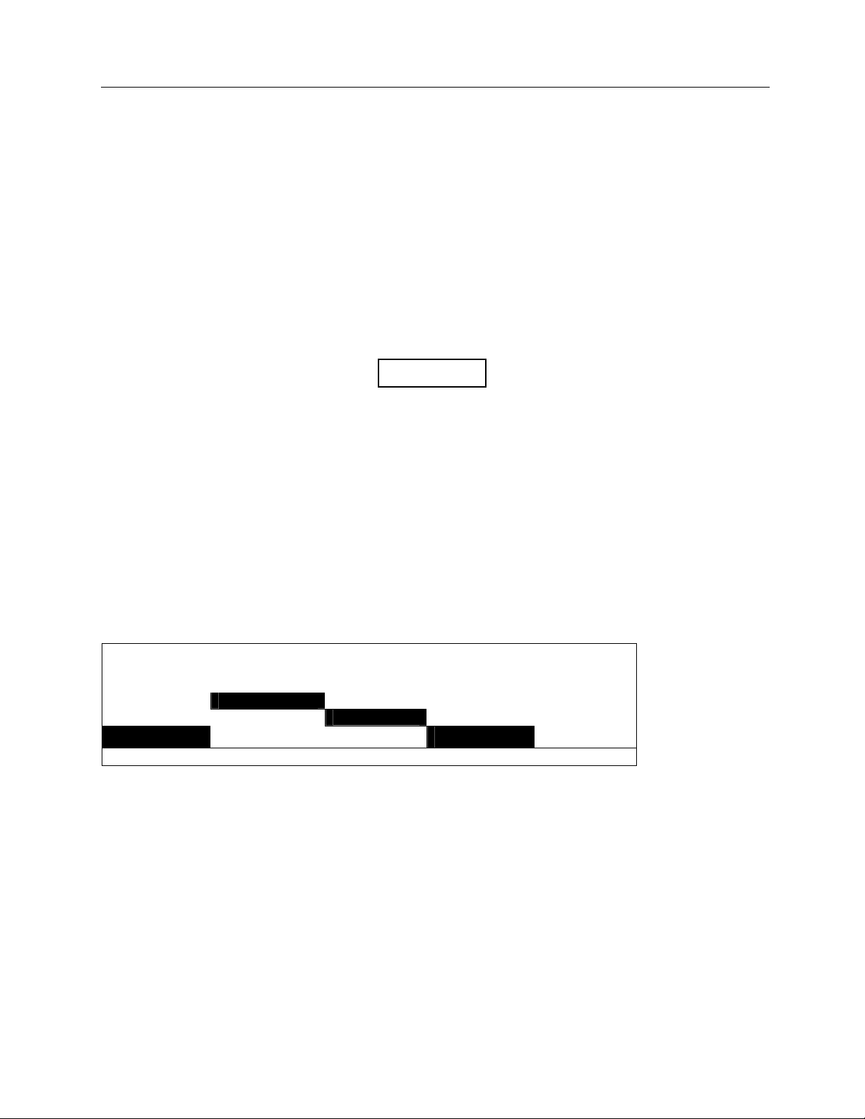
When a negative measurement delay is specified, the NERO mAx does not include the delay time in the
measured exposure time. A negative measurement delay should be used in cases when x-ray generator
filament preheat pulses or other waveform anomalies should be excluded from kV and exposure time
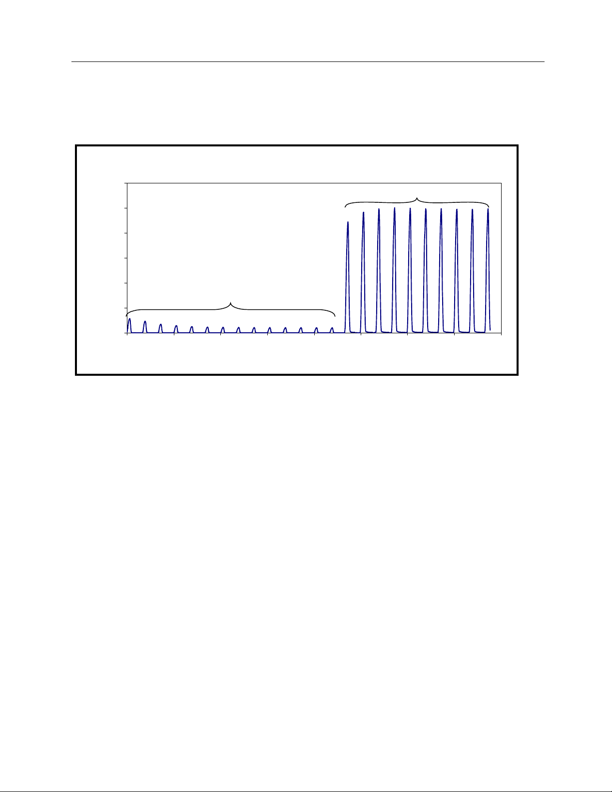
measurements. In the example shown below, a 10-pulse exposure is preceded by 14 filament preheat
pulses. Using a -230 millisecond delay to skip over the filament preheat pulses results in a measured
Negative Measurement Delay
Relative Radiation
120%
100%
80%
60%
40%
20%
0%
0 50 100 150 200 250 300 350 400
A negative delay is used to skip over
filament preheat pulses
msec
Exposure time measured
with a negative delay
exposure time of 10 pulses.
An example showing this use of a measurement delay can also be found in troubleshooting Section 4.8-Waveforms - Dental With Filament Preheat.
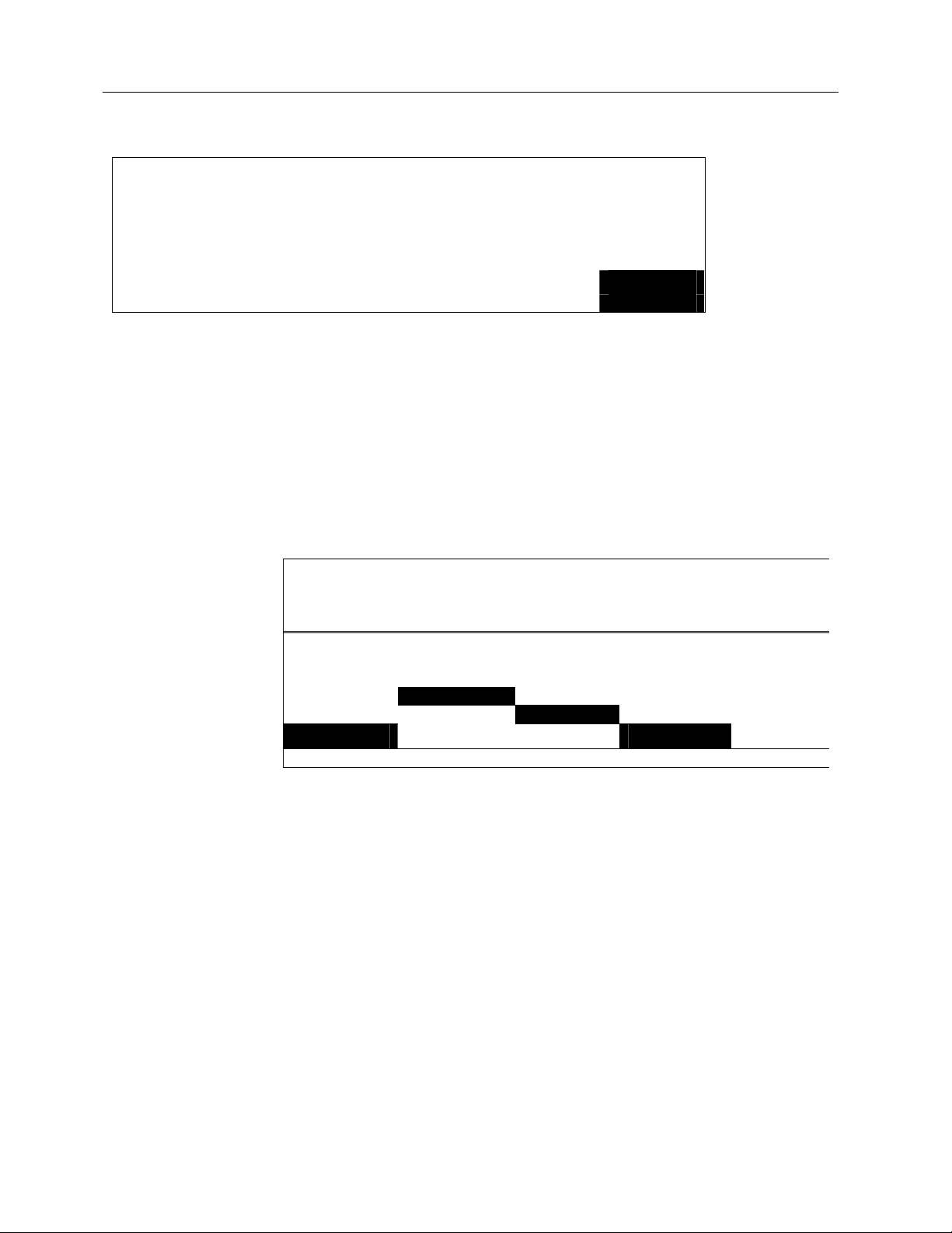
When the measurement delay is positive, the NERO mAx includes the delay time in its measured
exposure time. A positive measurement delay should be used in cases when the kV waveform contains
leading edge overshoot or other waveform anomalies that should be excluded from kV measurements but
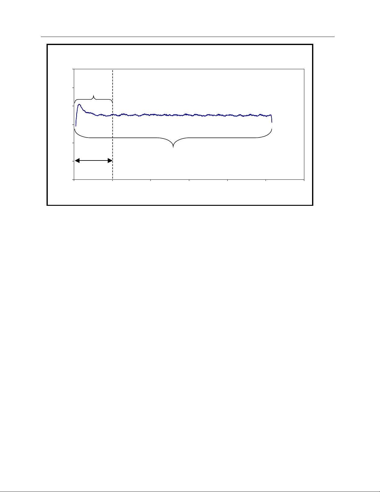
included in the exposure time measurement. In the example shown below, an overshoot occurs in the
first few milliseconds of a 50-millisecond exposure. Using a +10 millisecond delay to skip the overshoot
results in a measured kVp of 72 versus 82 and an exposure time of approximately 50 milliseconds.
2-15
Page 28
Victoreen 8000
Operators Manual
Positive Measurement Delay
120
A positive delay
100
is used to skip
overshoots
80
60
kV
40
Exposure time measured with positive delay
20
10 mill isecond
delay
0
0 102030405060
msec
An example showing this use of a measurement delay can be found in troubleshooting Section 4.5-Waveforms - Overshoot.
When a positive measurement delay is used in making a measurement in the Radio or Mammo mode,
the measured exposure time may be slightly longer than the exposure time between the selected %kV
points on the kV waveform. This is because the Model 8000 does not store the leading edge of the x-ray
output waveform when a measurement delay is used; it waits for the specified delay time before acquiring
waveform data. As a result of this, the %kV point on the rising edge of the kV waveform is not stored and
the time from exposure start to this point cannot be subtracted from the total time.
When exposure time is measured in pulses (1ØPULSE), use of a measurement delay may cause an error
in the pulse count because no pulses are counted during the delay time. The polarity of the delay has no
effect on pulse counting; for example, the number of pulses counted with a -10 millisecond delay is the
same as the number counted with a +10 millisecond delay.
When using a measurement delay in pulsed and single-phase applications, care must be used in
determining the correct delay period. If x-rays are detected at the end of the delay period, such as during
a pulse, the NERO mAx begins timing immediately. If no x-rays are detected at the end of the delay
period, such as between pulses, the NERO mAx waits up to one second for the beginning of the next
pulse to begin timing. As a result of this, the delay period should terminate prior to the first x-ray pulse to
be included in data analysis.
The NERO mAx Excel Add-In should be used to view radiation and kV waveforms to determine the
optimum measurement delay to use. Information on using the NERO mAx Excel Add-In to view
waveforms may be found in the NERO mAx Toolkit for Excel Instruction Manual. In addition, a digital
storage oscilloscope may be connected to the scope output on the rear panel of the NERO mAx readout
to view radiation output waveforms. Information on using the NERO mAx scope output may be found in
Section 1.6 of the NERO mAx instruction manual.
2-16
Page 29
Operation
Modes of Operation
2
Using %kV and Exposure Time Measurements
The %kV setting determines how the NERO mAx measures exposure time. When 75%, 80%, or 90% kV
is selected, the NERO mAx measures exposure time between the 75%, 80%, or 90% points on the kV
waveform. For best results when selecting 75%, 80%, or 90% kV, make sure that the percentage of the
kV waveforms peak kV is within the selected filter range. If the %kV or the measured kV is too low, a
"%kV TOO LOW" error message will be displayed.
When zero crossing (ZERO) is selected, the NERO mAx measures radiographic exposure time from the
moment x-rays are detected by the NERO mAx until they are no longer detected. This corresponds to the
time between first and last passage through the NERO mAx internal radiation detection threshold of the
channel A radiation signal. When using zero crossing, measured exposure times may be lengthened by
cable charging or by output filter capacitors used in some single phase generators to smooth the
generator’s output waveform.
When 1ØPULSE is selected, the NERO mAx counts the number of x-ray pulses in a pulsed or singlephase radiographic exposure. Pulses are detected by counting each passage through the NERO mAx
internal radiation detection threshold of the rising and falling edges of the pulses on channel A radiation
signal. This is primarily for use with single-phase full and half-wave rectified generators. Pulse counting
may not function properly on single-phase generators employing output filter capacitors to smooth the
generator’s output because the generator’s output may not drop to zero between pulses. Additionally,
use of a measurement delay may cause an error in the pulse count. For more information, see "Using a
Measurement Delay".
When calculating kVp average, the NERO mAx only includes peaks that are above the selected %kV in
the kVp average calculation. When ZERO or 1ØPULSE are selected, the NERO mAx includes all
detected peaks in the kVp average calculation.
2.5.2 Mammo Mode
Mammo mode is used to make measurements on mammographic generators. Mammo mode
simultaneously measures kVp, exposure time and mAs from a single mammographic exposure.
Exposure time in the Mammo mode is measured between the first and last passage through the 90%
points on the kV waveform. A measurement delay of up to 999 milliseconds may be used to delay the
start of kV data acquisition in order to skip over waveform anomalies at the beginning of an exposure.
See "Using a Measurement Delay" (at the end of this section) for more information on using a
measurement delay.
To make a mammographic measurement
Make sure that the NERO mAx is turned off. Plug one end of the NERO mAx’s detector cable into the
NERO mAx detector. Plug the other end of the detector cable into the NERO mAx’s detector connector.
Insert the MAMMO filter card into the detector and place the filter card in the correct position for the x-ray
tube target material. Place the NERO mAx detector on the x-ray table with the top of the detector facing
the x-ray tube. Position the detector so that the detector is centered in the beam and is aligned with the
x-ray tube axis. If mAs measurements are to be made, plug the mAs cable into the NERO mAx detector’s
mAs input and connect the mAs leads to the generators mAs terminals. For more information on
positioning the NERO mAx detector, see section "Positioning the Detector".
Extreme caution should be used when making
connections to the mAs terminals of the X-ray
generator or detector. Improper connections may
result in injury, damage to the NERO mAx, and/or
damage to the x-ray generator.
WARNING
2-17
Page 30
Victoreen 8000
Operators Manual
If results are to be printed, plug the printer cable into the printer port at the rear of the NERO mAx then
plug the other end of the printer cable into the printer and turn the printer on (see Section 1.5--Printing).
Plug the AC adapter into the NERO mAx if needed (see Section 1.4--Battery Operation and Charging)
and turn the instrument on.
EXP
CT EXP
AMSE
FLUORO Mo 30μ
MAMMO LOW RHODIUM Rh 25μ
RADIO HIGH MOLY Al 1MM 0 ms
MODE SENS TARGET FILTER DELAY
Select the MAMMO mode, high or low sensitivity, target and filter and shot delay, then press the ENTER
key. To use a measurement delay, press the DELAY key to select and increment the shot delay. The
measurement delay may also be incremented or decremented by pressing the up or down keys when the
delay is selected. The measurement delay is retained from one exposure to the next and can only be
reset to zero by the user.
Please wait…
FILTER = 22 - 35
MAMMO HIGH MOLY Mo 30μ 0 ms
MODE SENS TARGET FILTER DELAY
Please wait while the NERO mAx prepares to take an exposure. Note that the selected filter kV range is
displayed. If the NERO mAx detects a fault condition such as an invalid filter card or position, an error
message is displayed and the user must correct the error to continue (see Section 4.3--Error Messages-for more information). When the NERO mAx is ready to take an exposure it will beep and prompt for an
exposure.
MAKE EXPOSURE
FILTER = 22 - 35
MAMMO HIGH MOLY Mo 30μ 0 ms
MODE SENS TARGET FILTER DELAY
Make an exposure. If nothing happens, there is insufficient x-ray intensity to make a measurement. To
remedy this situation, switch to high sensitivity, increase mA or decrease the distance between the x-ray
tube and NERO mAx detector.
ANALYZING DATA
FILTER = 22 - 35
MAMMO HIGH MOLY Mo 30μ 0 ms
MODE SENS TARGET FILTER DELAY
Please wait while the NERO mAx analyzes the exposure data.
2-18
Page 31

Operation
Modes of Operation
2
24.8
24.3
27.3
MAMMO HIGH MOLY Mo 30μ MAKE
MODE SENS TARGET FILTER EXPOSURE
After data analysis is complete, kV, exposure, time and mAs are displayed. If an overrange is detected
an error message is displayed. If the calculated kV is above or below the selected filter kV range, “High”
or “Low” is displayed instead of kV and measured time may be “----“ (see Section 4.3--Error Messages-for more information). Please wait while the NERO mAx prepares for the next exposure. If the NERO
mAx detects a fault condition such as an invalid filter card or position, an error message is displayed and
the user must correct the error to continue (see Section 4.3--Error Messages--for more information).
The NERO mAx is now ready to take another exposure. Pressing the mode key at any time exits from
this measurement mode and returns to the mode selection screen.
24.8
24.3
27.3
MAMMO HIGH MOLY Mo 30μ Please
MODE SENS TARGET FILTER Wait…
As a power saving feature, the NERO mAx’s display backlight turns off after one minute of no activity.
The backlight turns back on when any button is pressed or an exposure is made. In addition, after five
minutes of no activity, the NERO mAx exits from any measurement mode and returns to the mode
selection screen.
kVp Avg
kV Eff
kV Peak
kVp Avg
kV Eff
kV Peak
226.5
240.3
19.9
226.5
240.3
19.9
msec
mR
mAs
msec
mR
mAs
Using A Measurement Delay
A measurement delay may be used to postpone the start of data acquisition in order to skip over
waveform anomalies (such as overshoots) that may occur at the beginning of an exposure. The delay
range is from -999 to +999 milliseconds, and the polarity of the measurement delay only affects how
exposure time measurements are performed.
When the measurement delay is positive, the NERO mAx includes the delay time in its measured
exposure time. A positive measurement delay should be used in cases when the kV waveform contains
leading edge overshoot or other waveform anomalies that should be excluded from kV measurements but
included in the exposure time measurement.
When a negative measurement delay is specified, the NERO mAx does not include the delay time in the
measured exposure time. A negative measurement delay should be used in cases when x-ray generator
filament preheat pulses or other waveform anomalies should be excluded from kV and exposure time
measurements.
More information on using a measurement delay may be found in “Using a Measurement Delay” at the
end of Section 2.5.1--Radio Mode.
2-19
Page 32

Victoreen 8000
Operators Manual
2.5.3 Fluoro Mode
Fluoro mode is used to make measurements on fluoroscopic x-ray generators. Fluoro mode supports
both continuous fluoro and pulsed fluoro measurements. In the continuous fluoro mode, the NERO mAx
measures kVp, exposure rate (R/min) and mA. In the pulsed fluoro mode, the NERO mAx measures kVp,
exposure rate (R/min and mR/pulse) and mAs/pulse.
To make a continuous fluoro measurement
Make sure that the NERO mAx is turned off. Plug one end of the NERO mAx’s detector cable into the
NERO mAx detector. Plug the other end of the detector cable into the NERO mAx’s detector connector.
Insert the W/Al filter card into the detector and place the filter card in the correct position for the kV range
to be measured. Place the NERO mAx detector on the x-ray table with the top of the detector facing the
x-ray tube. Position the detector so that the detector is centered in the beam and is aligned with the x-ray
tube axis. If mA measurements are to be made, plug the mAs cable into the NERO mAx detector’s mAs
input and connect the mAs leads to the generators mAs terminals. For more information on positioning
the NERO mAx detector, see section "Positioning the Detector". For mA limits vs. kV, refer to Appendix
B.
Extreme caution should be used when making
connections to the mAs terminals of the X-ray
generator or detector. Improper connections may
result in injury, damage to the NERO mAx, and/or
damage to the x-ray generator.
If results are to be printed, plug the printer cable into the printer port at the rear of the NERO mAx then
plug the other end of the printer cable into the printer and turn the printer on (see Section 1.5--Printing).
Plug the AC adapter into the NERO mAx if needed (see Section 1.4--Battery Operation and Charging)
and turn the instrument on.
WARNING
EXP
CT EXP
AMSE
FLUORO
MAMMO PULSED LOW
RADIO CONT HIGH
MODE TYPE SENS
Select fluoro mode, continuous generator type and sensitivity, then press enter.
Please wait…
FILTER = 50 - 100
FLUORO CONT HIGH
MODE TYPE SENS
Please wait while the NERO mAx prepares to take an exposure. Note that the selected filter kV range is
displayed. If the NERO mAx detects a fault condition such as an invalid filter card or position, an error
message is displayed and the user must correct the error to continue (see Section 4.3--Error Messages-for more information). When the NERO mAx is ready to take an exposure it will beep and prompt for an
exposure.
2-20
Page 33

Modes of Operation
MAKE EXPOSURE
FILTER = 50 - 100
FLUORO CONT HIGH
MODE TYPE SENS
Start the fluoroscopic exposure.
Operation
2
4.49
4.1
FLUORO CONT HIGH
MODE TYPE SENS SAVE
After the exposure starts, the NERO mAx displays exposure rate and mA. When the desired exposure
rate and/or mA are displayed, press the SAVE key to acquire kV data.
4.49
4.1
FLUORO CONT HIGH TURN OFF
MODE TYPE SENS BEAM
After kV data is acquired, the NERO mAx prompts to turn off the beam.
4.49
4.1
R/min
mA
R/min
mA
R/min
mA
FLUORO CONT HIGH ANALYZE
MODE TYPE SENS DATA
After the beam is turned off, the NERO mAx analyzes the fluoro exposure kV data.
89.6
87.8
91.9
FLUORO CONT HIGH Please
MODE TYPE SENS Wait…
After data analysis is complete, kV, exposure rate and mA are displayed. If an overrange is detected an
error message is displayed. If the calculated kV is above or below the selected filter kV range, “High” or
kVp Avg
kV Eff
kV Peak
4.34
4.1
R/min
mA
2-21
Page 34

Victoreen 8000
Operators Manual
“Low” is displayed instead of kV (see Section 4.3--Error Messages--for more information). After the
exposure data is displayed, the NERO mAx displays a "Please wait..." message as it prepares for the
next exposure.
89.6
87.8
91.9
FLUORO CONT HIGH MAKE
MODE TYPE SENS EXPOSURE
The NERO mAx is now ready to take another exposure. Pressing the mode key at any time exits from
this measurement mode and returns to the mode selection screen.
As a power saving feature, the NERO mAx’s display backlight turns off after one minute of no activity.
The backlight turns back on when any button is pressed or an exposure is made. In addition, after five
minutes of no activity, the NERO mAx exits from any measurement mode and returns to the mode
selection screen.
kVp Avg
kV Eff
kV Peak
4.34
4.1
NOTE
The exposure rate displayed after the SAVE key
has been pressed may be slightly different from the
rate displayed before the stop key was pressed.
This is because the exposure rate is calculated
based upon correction factors that are based upon
the measured kVp. In the fluoro mode, kVp is not
measured until after the SAVE key is pressed, so a
constant is used to calculate exposure and rate.
The constant that is used is based upon the
calibration factors corresponding to a kVp average
of the mid point of the selected filter range. After
the SAVE key is pressed, the NERO mAx
calculates the fluoro kVp and applies an exposure
correction factor based upon the calculated kVp.
R/min
mA
To make a pulsed fluoro measurement
Make sure that the NERO mAx is turned off. Plug one end of the NERO mAx’s detector cable into the
NERO mAx detector. Plug the other end of the detector cable into the NERO mAx’s detector connector.
Insert the W/Al filter card into the detector and place the filter card in the correct position for the kV range
to be measured. Place the NERO mAx detector on the x-ray table with the top of the detector facing the
x-ray tube. Position the detector so that the detector is centered in the beam and is aligned with the x-ray
tube axis. If mAs measurements are to be made, plug the mAs cable into the NERO mAx detector’s mAs
input and connect the mAs leads to the generators mAs terminals. For more information on positioning
the NERO mAx detector, see section "Positioning the Detector". For mA limits vs. kV, refer to Appendix
B.
2-22
Page 35

Operation
Modes of Operation
WARNING
Extreme caution should be used when making
connections to the mAs terminals of the X-ray
generator or detector. Improper connections may
result in injury, damage to the NERO mAx, and/or
damage to the x-ray generator.
If results are to be printed, plug the printer cable into the printer port at the rear of the NERO mAx then
plug the other end of the printer cable into the printer and turn the printer on (see Section 1.5--Printing).
Plug the AC adapter into the NERO mAx if needed (see Section 1.4--Battery Operation and Charging)
and turn the instrument on.
EXP
CT EXP
AMSE
FLUORO
MAMMO PULSED LOW
RADIO CONT HIGH
MODE TYPE SENS
2
Select fluoro mode, pulsed generator type and sensitivity, then press enter.
Please wait…
FILTER = 50 - 100
FLUORO PULSED LOW
MODE TYPE SENS
Please wait while the NERO mAx prepares to take an exposure. Note that the selected filter kV range is
displayed. If the NERO mAx detects a fault condition such as an invalid filter card or position, an error
message is displayed and the user must correct the error to continue (see Section 4.3--Error Messages-for more information). When the NERO mAx is ready to take an exposure it will beep and prompt for an
exposure.
MAKE EXPOSURE
FILTER = 50 - 100
FLUORO PULSED LOW
MODE TYPE SENS
Start the fluoroscopic exposure.
2-23
Page 36

Victoreen 8000
Operators Manual
318
0.28
FLUORO PULSED LOW
MODE TYPE SENS SAVE
After the exposure starts, the NERO mAx displays exposure rate (R/min, mR/pulse) and mAs/pulse.
When the desired exposure rate and/or mAs/pulse are displayed, press the SAVE key to acquire kV data.
318
0.28
FLUORO PULSED LOW TURN OFF
MODE TYPE SENS BEAM
After kV data is acquired, the NERO mAx prompts to turn off the beam.
318
μR/pulse
mAs/pulse
0
R/min
μR/pulse
mAs/pulse
0
R/min
μR/pulse
mAs/pulse
0
0.28
FLUORO PULSED LOW ANALYZE
MODE TYPE SENS DATA
After the beam is turned off, the NERO mAx analyzes the fluoro exposure kV data.
318
0.28
FLUORO PULSED LOW Please
MODE TYPE SENS Wait…
After data analysis is complete, kV, exposure rate and mAs/pulse are displayed. If an overrange is
detected an error message is displayed. If the calculated kV is above or below the selected filter kV
range, “High” or “Low” is displayed instead of kV (see Section 4.3--Error Messages--for more information).
After the exposure data is displayed, the NERO mAx displays a "Please wait..." message as it prepares
for the next exposure.
R/min
μR/pulse
mAs/pulse
0
R/min
2-24
Page 37

Operation
Modes of Operation
2
97.5
93.9
104.6
FLUORO PULSED LOW MAKE
MODE TYPE SENS EXPOSURE
The NERO mAx is now ready to take another exposure. Pressing the mode key at any time exits from
this measurement mode and returns to the mode selection screen.
As a power saving feature, the NERO mAx’s display backlight turns off after one minute of no activity.
The backlight turns back on when any button is pressed or an exposure is made. In addition, after five
minutes of no activity, the NERO mAx exits from any measurement mode and returns to the mode
selection screen.
kVp Avg
kV Eff
kV Peak
The exposure rate displayed after the SAVE key
has been pressed may be slightly different from the
rate displayed before the stop key was pressed.
This is because the exposure rate is calculated
based upon correction factors that are based upon
the measured kVp. In the fluoro mode, kVp is not
measured until after the SAVE key is pressed, so a
constant is used to calculate exposure and rate.
The constant that is used is based upon the
calibration factors corresponding to a kVp average
of the mid point of the selected filter range. After
the SAVE key is pressed, the NERO mAx
calculates the fluoro kVp and applies an exposure
correction factor based upon the calculated kVp.
0.28
311
NOTE
R/min
mAs/pulse
0
µR/pulse
2.5.4 AMSE Mode
AMSE mode is used for Automated Measurement of Sequential Exposures. This mode is used to
measure the output of CINE x-ray generators. In AMSE mode, the NERO mAx measures kVp, exposure
rate (mR/frame), mAs/frame and time/frame (mS/frame).
To make an AMSE measurement
Make sure that the NERO mAx is turned off. Plug one end of the NERO mAx’s detector cable into the
NERO mAx detector. Plug the other end of the detector cable into the NERO mAx’s detector connector.
Insert the W/Al filter card into the detector and place the filter card in the correct position for the kV range
to be measured. Place the NERO mAx detector on the x-ray table with the top of the detector facing the
x-ray tube. Position the detector so that the detector is centered in the beam and is aligned with the x-ray
tube axis. If mAs measurements are to be made, plug the mAs cable into the NERO mAx detector’s mAs
input and connect the mAs leads to the generators mAs terminals. For more information on positioning
the NERO mAx detector, see section "Positioning the Detector". For mA limits vs. kV, refer to Appendix
B.
2-25
Page 38

Victoreen 8000
Operators Manual
WARNING
Extreme caution should be used when making
connections to the mAs terminals of the X-ray
generator or detector. Improper connections may
result in injury, damage to the NERO mAx, and/or
damage to the x-ray generator.
If results are to be printed, plug the printer cable into the printer port at the rear of the NERO mAx then
plug the other end of the printer cable into the printer and turn the printer on (see Section1.5--Printing).
Plug the AC adapter into the NERO mAx if needed (see Section 1.4--Battery Operation and Charging)
and turn the instrument on.
EXP
CT EXP
AMSE
FLUORO
MAMMO LOW
RADIO HIGH
MODE SENS
Select AMSE mode and sensitivity, then press enter.
Please wait…
FILTER = 50 - 100
AMSE LOW
MODE SENS
Please wait while the NERO mAx prepares to take an exposure. Note that the selected filter kV range is
displayed. If the NERO mAx detects a fault condition such as an invalid filter card or position, an error
message is displayed and the user must correct the error to continue (see Section 4.3--Error Messages-for more information). When the NERO mAx is ready to take an exposure it will beep and prompt for an
exposure.
MAKE EXPOSURE
FILTER = 50 – 100
AMSE LOW
MODE SENS
Start the exposure.
2-26
Page 39

Operation
Modes of Operation
2
250.9
45.6
AMSE LOW
MODE SENS SAVE
After the exposure starts, the NERO mAx displays exposure/frame and mAs/frame. When the desired
exposure rate is displayed, press the SAVE key to acquire kV data.
250.9
45.6
AMSE LOW TURN OFF
MODE SENS BEAM
After kV data is acquired, the NERO mAx prompts to turn off the beam.
250.9
45.6
mR/frame
mAs/frame
mR/frame
mAs/frame
mR/frame
mAs/frame
AMSE LOW ANALYZE
MODE SENS DATA
After the beam is turned off, the NERO mAx analyzes the fluoro exposure kV data.
65.6
65.0
67.2
AMSE LOW Please
MODE SENS Wait…
After data analysis is complete, kV, exposure rate, mAs/frame and time/frame are displayed. If an
overrange is detected an error message is displayed. If the calculated kV is above or below the selected
filter kV range, “High” or “Low” is displayed instead of kV (see Section 4.3--Error Messages--for more
information). After the exposure data is displayed, the NERO mAx displays a "Please wait..." message as
it prepares for the next exposure.
kVp Avg
kV Eff
kV Peak
57
250.9
45.6
msec/frame
mR/frame
mAs/frame
2-27
Page 40

Victoreen 8000
Operators Manual
65.6
65.0
67.2
AMSE LOW MAKE
MODE SENS EXPOSURE
The NERO mAx is now ready to take another exposure. Pressing the mode key at any time exits from
this measurement mode and returns to the mode selection screen.
As a power saving feature, the NERO mAx’s display backlight turns off after one minute of no activity.
The backlight turns back on when any button is pressed or an exposure is made. In addition, after five
minutes of no activity, the NERO mAx exits from any measurement mode and returns to the mode
selection screen.
kVp Avg
kV Eff
kV Peak
The exposure rate displayed after the SAVE key
has been pressed may be slightly different from the
rate displayed before the stop key was pressed.
This is because the exposure rate is calculated
based upon correction factors that are based upon
the measured kVp. In the AMSE mode, kVp is not
measured until after the SAVE key is pressed, so a
constant is used to calculate exposure and rate.
The constant that is used is based upon the
calibration factors corresponding to a kVp average
of the mid point of the selected filter range. After
the SAVE key is pressed, the NERO mAx
calculates kVp and applies an exposure correction
factor based upon the calculated kVp.
57
250.9
45.6
NOTE
msec/frame
mR/frame
mAs/frame
2.5.5 CT Exposure Mode
CT Exposure mode is used to make CT exposure measurements using the Victoreen 6000-100 or 6000200 CT ion chamber. A CT probe must be connected to the 8000 detector’s external ion chamber input
in this mode. The exposure is calculated using the user entered beam width (in mm) and the CT probe’s
calibration factor (Rcm/nC). This mode functions in the same manner as the Exposure Mode with the
addition of beam width entry.
To make a CT exposure measurement
Make sure that the NERO mAx is turned off. Plug one end of the NERO mAx’s detector cable into the
NERO mAx detector. Plug the other end of the detector cable into the NERO mAx’s detector connector.
No filter card needs to be present in the detector. Plug the CT chamber’s BNC connector into the ion
chamber signal input at the rear of the NERO mAx detector. Plug the CT chamber’s bias plug (banana
jack) into the bias output at the rear of the NERO mAx detector. Position the ion chamber as needed.
If results are to be printed, plug the printer cable into the printer port at the rear of the NERO mAx then
plug the other end of the printer cable into the printer and turn the printer on (see Section 1.5--Printing).
2-28
Page 41

Operation
Modes of Operation
Plug the AC adapter into the NERO mAx if needed (see Section 1.4--Battery Operation and Charging)
and turn the instrument on.
WARNING
An electric shock hazard exists between the ion
chamber bias connector and ground.
EXP
CT EXP
AMSE
FLUORO
MAMMO LOW
RADIO HIGH 10 mm
MODE SENS BEAM
Select CT EXP mode, high or low sensitivity and beam width (1-10 mm), then press the ENTER key.
Pressing the BEAM softkey (2) or the UP key increments the beam width by 1 mm, pressing the DOWN
button decrements the beam width by 1 mm.
Please wait…
CT EXP HIGH 10 mm
MODE SENS BEAM
Please wait while the NERO mAx prepares to take an exposure. If the NERO mAx detects a fault
condition such as a high offset, an error message is displayed and the user must correct the error to
continue (see Section 4.3--Error Messages--for more information).
2
CT EXP HIGH 10 mm
MODE SENS BEAM RESET
When the NERO mAx is ready to take an exposure it will beep and display zero exposure.
CT EXP HIGH 10 mm
MODE SENS BEAM RESET
After the exposure ends, the measured exposure for the scan is displayed. If an overrange occurs, an
error message will be displayed (see Section 4.3--Error Messages--for more information). When the
exposure ends, the NERO mAx auto-resets before the next exposure while retaining the measured
exposure data on screen. The NERO mAx beeps when auto reset is complete and the NERO mAx is
ready for the next exposure. Press the RESET softkey (4) to zero the display or press the mode key to
exit. Do not press the RESET softkey when the beam is on. Inaccurate readings will result.
0.00 R
6.72 R
2-29
Page 42

Victoreen 8000
Operators Manual
As a power saving feature, the NERO mAx’s display backlight turns off after one minute of no activity.
The backlight turns back on when any button is pressed or an exposure is made. In addition, after five
minutes of no activity, the NERO mAx exits from any measurement mode and returns to the mode
selection screen.
2.5.6 Exp Mode
Exposure mode is used to make exposure and rate measurements using the NERO mAx’s internal ion
chamber or an external ion chamber. The exposure is calculated using the selected ion chamber’s
calibration factor (along with air density correction). For more information about entry and storage of ion
chamber calibration factors, see CAL mode. For more information about selecting exposure/rate units,
see SETUP mode. All exposure and rate measurements are corrected for user entered air density. For
more information about entering air density data, see SETUP mode.
Exposure and rate measurements made with the NERO mAx’s internal ion chamber in this mode are
calculated using a constant calibration factor and air density correction. In measurement modes where
kV is measured, exposure and rate are calculated using calibration factors based upon the measured kV.
In the exposure mode, no kV measurements are made, so a constant is used to calculate exposure and
rate. The constant that is used is based upon the calibration factors corresponding to a measured kVp
average of 80 kVp. A user entered calibration factor (multiplier) allows the user to adjust the calibration of
the internal ion chamber. The default for this calibration factor is 1.00 E+00. For more information about
entry and storage of ion chamber calibration factors, see CAL mode. For more information about entry of
air density information (temperature and pressure), see SETUP mode.
Exposure and rate measurements made with the external ion chambers are calculated using the stored
calibration factor (R/nC or Gy/nC) for the selected external chamber and air density correction. For more
information about entry of air density information (temperature and pressure), see SETUP mode.
To make an exposure or rate measurement
Make sure that the NERO mAx is turned off. Plug one end of the NERO mAx’s detector cable into the
NERO mAx detector. Plug the other end of the detector cable into the NERO mAx’s detector connector.
No filter card is required for exposure or rate measurements. If using an external ion chamber, plug the
ion chamber’s BNC connector into the ion chamber signal input at the rear of the NERO mAx detector.
Plug the chamber’s bias plug (banana jack) into the bias output at the rear of the NERO mAx detector.
Position the ion chamber as needed. If using the NERO mAx’s internal ion chamber, position the NERO
mAx detector as needed.
WARNING
An electric shock hazard exists between the ion
chamber bias connector and ground.
If results are to be printed, plug the printer cable into the printer port at the rear of the NERO mAx then
plug the other end of the printer cable into the printer and turn the printer on (see Section 1.5--Printing).
Plug the AC adapter into the NERO mAx if needed (see Section 1.4--Battery Operation and Charging)
and turn the instrument on.
2-30
Page 43

Operation
Modes of Operation
EXP
CT EXP SCATTER
AMSE MAMMO
FLUORO FLUORO
MAMMO R/F RATE LOW
RADIO INTERN INTEG HIGH
MODE CHAMBER MODE SENS
Select EXP mode, the ion chamber to be used, rate or integrate mode, high or low sensitivity, then press
the ENTER key.
Please wait…
EXP FLUORO INTEG HIGH
MODE CHAMBER MODE SENS
Please wait approximately ten seconds while the NERO mAx prepares to take an exposure. If the NERO
mAx detects a fault condition such as a high offset, an error message is displayed and the user must
correct the error to continue (see Section 4.3--Error Messages--for more information).
2
EXP FLUORO INTEG HIGH
MODE CHAMBER MODE SENS RESET
When the NERO mAx is ready to take an exposure it will beep and display zero exposure units.
EXP FLUORO INTEG HIGH
MODE CHAMBER MODE SENS RESET
After the exposure ends, the measured exposure is displayed. If an overrange occurs, an error message
will be displayed (see Section 4.3--Error Messages--for more information). In the integrate mode, the
8000 auto-resets after an exposure while retaining the measured exposure data on screen. The NERO
mAx beeps when auto reset is complete and the NERO mAx is ready for another exposure. This autoreset feature is not present in the rate mode. Press the RESET softkey (4) to zero the display in the rate
and integrate modes or press the mode key to exit. Do not press the RESET softkey when the beam
is on. Inaccurate readings will result.
As a power saving feature, the NERO mAx’s display backlight turns off after one minute of no activity.
The backlight turns back on when any button is pressed or an exposure is made. In addition, after five
minutes of no activity, the NERO mAx exits from any measurement mode and returns to the mode
selection screen.
0.00 mR
1.23 mR
2-31
Page 44

Victoreen 8000
Operators Manual
2.5.7 HVL Mode
NOTE
In the HVL mode, the HVL report is printed only
after the mode key is depressed or 10 exposures
occur.
In the HVL mode, the NERO mAx calculates half value layer based upon a series of exposure or rate
measurements made with varying thickness’ of aluminum absorbers placed in the x-ray beam. A
minimum of two measurements are required and up to ten may be used. The exposure or rate
measurements may be made using the NERO mAx’s internal ion chamber or an external ion chamber.
Exposure and rate are calculated using the selected ion chamber’s calibration factor and when using a
CT chamber, beam width. For more information about entry and storage of ion chamber calibration
factors, see CAL mode. For more information about selecting exposure/rate units, see SETUP mode.
The default absorber thickness is 3.30 mmAl except when the Victoreen mammo chamber has been
selected. The default absorber thickness when using the mammo chamber is 0.30 mmAl. The HVL filter
thickness can be incremented or decremented from the default value by pressing the up or down keys.
Exposure and rate measurements made with the NERO mAx’s internal ion chamber, where kV is not
measured, are calculated using the ion chamber’s 80 kV calibration factors. In measurement modes
where kV is measured, exposure and rate are calculated using calibration factors based upon the
measured kV. In the HVL mode, no kV measurements are made, so a constant is used to calculate
exposure and rate. The constant that is used is based upon the calibration factors corresponding to a
measured kVp average of 80 kVp. A user entered calibration factor (multiplier) allows the user to adjust
the calibration of the internal ion chamber. For more information about entry and storage of ion chamber
calibration factors, see CAL mode.
HVL is calculated using a linear regression of the natural log of the normalized exposure (normalized to
the first exposure) versus absorber thickness in millimeters of aluminum. In addition, the correlation
coefficient (“r”) of the exposure data is calculated to provide an indication of how well the data fits the
linear regression. A poor fit (r < 0.98) is indicated by a flashing “r” value. The first exposure of the series
is made with no HVL absorber in place. All subsequent exposures must be made with an aluminum
absorber in the x-ray beam. The absorbers do not need to be placed in the beam in any order of
thickness. Below is the formula used by the NERO mAx to calculate half value layer.
()
BxAHVL +∗= ln
Where: x = Normalized dose at Half Value Layer (0.5)
A = Slope of ln(x) vs. mmAl
B = Intercept of ln(x) vs. mmAl (Usually very close to zero)
2-32
Page 45

Modes of Operation
For example, given the following table of exposure data:
Normalized ln Normalized
Exp
Linear Regression Results: A = -5.051 B = -0.000 r = -0.999
= -5.051*ln(0.5) + 0
= 3.5 mm Al
mm Al Dose(mR) Dose Dose
#
1 0 556 1.000 0.000
2 4.3 273 0.491 -0.711
3 3.8 296 0.532 -0.631
4 3.3 316 0.568 -0.566
5 4.8 256 0.460 -0.777
6 5.3 238 0.428 -0.849
()
BxAHVL +∗= ln
Operation
2
Note that in the table, the added filtration is near the half value layer. Calculating HVL in this manner
allows the user to improve the accuracy of the calculated HVL by making more exposures. Using this
method, the closer that the
HVL calculation will be. To assist in establishing the optimum average HVL filter thickness, the NERO
mAx displays either a “HIGH” or “LOW” message above the HVL if the average of the added filtration for
each exposure is not within 10% of the calculated HVL. If no messages are displayed, the average
added filtration is within 10% of the calculated HVL and no more exposures need to be made. As a
result, the NERO mAx guides the user to the correct HVL.
The accuracy of the HVL measurement depends upon the reproducibility of the x-ray parameters,
geometry errors and calculation errors caused by the approximation of the natural log of the normalized
exposure data to the actual attenuation curve. This calculation error is equal to zero if the filter thickness
for the second exposure reduces the exposure by exactly half.
When more than two exposures are made, the NERO mAx calculates the correlation coefficient (‘r’) of the
exposure and HVL filter thickness data to test the data for goodness of fit. The closer that the correlation
coefficient is to unity or one, the better the data fits the calculated approximation of the attenuation curve.
If the correlation coefficient is less than 0.98, the displayed “r” value flashes to indicate a poor fit. A low
correlation coefficient may be caused by poor x-ray output reproducibility, poor geometry or errors in filter
thickness. In addition, the larger the variation in filter thickness from one exposure to the next, the lower
the correlation coefficient.
To achieve optimal half value layer accuracy, the following are recommended:
1. The aluminum HVL filters must be placed at the collimator.
2. All exposures must be made at the same machine settings.
3. The output of the x-ray generator must be reproducible.
4. The field should be collimated to the detector or ion chamber.
5. Use HVL filter thickness’ that are near the actual HVL.
average of the added filtration is to the calculated HVL, the more accurate the
2-33
Page 46

Victoreen 8000
Operators Manual
To make HVL determination using exposure measurements
Make sure that the NERO mAx is turned off. Plug one end of the NERO mAx’s detector cable into the
NERO mAx detector. Plug the other end of the detector cable into the NERO mAx’s detector connector.
No filter card is required for exposure or rate measurements. If using an external ion chamber, plug the
ion chamber’s BNC connector into the ion chamber signal input at the rear of the NERO mAx detector.
Plug the chamber’s bias plug (banana jack) into the bias output at the rear of the NERO mAx detector.
Position the ion chamber as needed. If using the NERO mAx’s internal ion chamber, position the NERO
mAx detector as needed.
WARNING
An electric shock hazard exists between the ion
chamber bias connector and ground.
If results are to be printed, plug the printer cable into the printer port at the rear of the NERO mAx then
plug the other end of the printer cable into the printer and turn the printer on (see Section 1.5--Printing).
Plug the AC adapter into the NERO mAx if needed (see Section 1.4--Battery Operation and Charging)
and turn the instrument on.
HVL
EXP CT
CT EXP MAMMO
AMSE FLUORO
FLUORO R/F RATE LOW
MAMMO INTERN INTEG HIGH
MODE CHAMBER MODE SENS
Select HVL mode, the ion chamber to be used, integrate mode, high or low sensitivity, then press the
ENTER key.
2-34
Page 47

Modes of Operation
Operation
2
0 mR
HVL MAMMO INTEG HIGH
MODE CHAMBER MODE SENS
Please wait while the NERO mAx prepares to take an exposure. If the NERO mAx detects a fault
condition such as a high offset, an error message is displayed and the user must correct the error to
continue (see Section 4.3--Error Messages--for more information). When the NERO mAx is ready to take
an exposure it will beep and prompt for an exposure.
0 mR
HVL MAMMO INTEG HIGH
MODE CHAMBER MODE SENS
Make the first exposure with no filtration in the beam.
368 mR
HVL MAMMO INTEG HIGH
MODE CHAMBER MODE SENS REJECT
The exposure data from the first exposure is displayed and the NERO mAx prepares to take the second
exposure. Please wait while the NERO mAx prepares to take the next exposure. If the NERO mAx
detects a fault condition such as a high offset, an error message is displayed and the user must correct
the error to continue (see Section 4.3--Error Messages--for more information).
MAKE EXPOSURE # 01
Please wait…
Please wait…
368 mR
HVL MAMMO INTEG
MODE CHAMBER MODE SENS REJECT
The NERO mAx is now ready to take the next exposure. Position an aluminum absorber in the beam and
make the exposure. If the previously measured exposure is not acceptable, press the reject softkey to
retake the exposure. If an overrange occurs, an error message is displayed and the exposure must be
taken over.
MAKE EXPOSURE # 02
HIGH
2-35
Page 48

Victoreen 8000
Operators Manual
183 mR
Enter Thickness: 030 mmAl EXPOSURE # 02
HVL
MODE THICKNESS REJECT
The exposure data from the second exposure is now displayed and the user is prompted to enter the
thickness of the aluminum filter. To enter the filter thickness, press the THICKNESS softkey to
increment the filter thickness or use the UP and DOWN keys to increment and decrement the filter
thickness. If a filter thickness is repeated, the NERO mAx will ask for confirmation that the latest
exposure data is to be accepted. When the correct filter thickness is displayed, press the ENTER key.
Pressing the enter key accepts the HVL exposure data after the absorber thickness has been entered.
Pressing the reject key rejects the exposure data and the user is prompted to make the exposure over.
183 mR HVL 0.27
Please Wait…
HVL MAMMO INTEG
MODE CHAMBER MODE SENS
The HVL is calculated and displayed after the new exposure data has been entered and a “Please wait…”
message is displayed while the NERO mAx prepares for the next exposure. If the NERO mAx displays
“LOW” above the calculated HVL, the average of the added filtration is more than 10% less than the
calculated HVL and more aluminum filtration is needed. If the NERO mAx displays “HIGH” above the
calculated HVL, the added filtration is more than 10% above the calculated HVL and some of the
aluminum filtration should be removed. When more than two exposures have been made, the NERO
mAx checks the HVL data for goodness of fit by calculating its correlation coefficient (“r”), if the fit is poor
(r< 0.98), the “r” value will flash.
mmAl
HIGH
183 mR HVL 0.27
MAKE EXPOSURE # 03
HVL MAMMO INTEG
MODE CHAMBER MODE SENS
The NERO mAx is now ready to take the next exposure. The NERO mAx stays in this measurement loop
until ten exposures have been made or the mode key is pressed, which exits to the mode selection
screen.
As a power saving feature, the NERO mAx’s display backlight turns off after one minute of no activity.
The backlight turns back on when any button is pressed or an exposure is made. In addition, after five
minutes of no activity, the NERO mAx exits from any measurement mode and returns to the mode
selection screen.
2-36
HIGH
mmAl
Page 49

Operation
Modes of Operation
2
(HVL) Exposure Rate
To make HVL determination using exposure rate measurements
Make sure that the NERO mAx is turned off. Plug one end of the NERO mAx’s detector cable into the
NERO mAx detector. Plug the other end of the detector cable into the NERO mAx’s detector connector.
No filter card is required for exposure or rate measurements. If using an external ion chamber, plug the
ion chamber’s BNC connector into the ion chamber signal input at the rear of the NERO mAx detector.
Plug the chamber’s bias plug (banana jack) into the bias output at the rear of the NERO mAx detector.
Position the ion chamber as needed. If using the NERO mAx’s internal ion chamber, position the NERO
mAx detector as needed.
WARNING
An electric shock hazard exists between the ion
chamber bias connector and ground.
If results are to be printed, plug the printer cable into the printer port at the rear of the NERO mAx then
plug the other end of the printer cable into the printer and turn the printer on (see Section 1.5--Printing).
Plug the AC adapter into the NERO mAx if needed (see Section 1.4--Battery Operation and Charging)
and turn the instrument on.
HVL
EXP CT
CT EXP MAMMO
AMSE FLUORO
FLUORO R/F RATE LOW
MAMMO INTERN INTEG HIGH
MODE CHAMBER MODE SENS
Select HVL mode, the ion chamber to be used, rate mode, high or low sensitivity, then press the ENTER
key.
0.0 R/min
Please Wait…
HVL INTERN RATE LOW
MODE CHAMBER MODE SENS
Please wait while the NERO mAx prepares to take an exposure. If the NERO mAx detects a fault
condition such as a high offset, an error message is displayed and the user must correct the error to
continue (see Section 4.3--Error Messages-- for more information). When the NERO mAx is ready to
take an exposure it will beep and prompt for an exposure.
9.8 R/min
MAKE EXPOSURE # 01
HVL INTERN RATE LOW
MODE CHAMBER MODE SENS
Turn the x-ray beam on with no filtration in the beam.
2-37
Page 50

Victoreen 8000
Operators Manual
9.8 R/min
HVL INTERN RATE LOW
MODE CHAMBER MODE SENS SAVE
After the exposure has started, the NERO mAx displays the exposure rate. When the rate has stabilized
or the desired rate has been achieved, press the SAVE softkey (softkey 4) to save the rate measurement.
9.8 R/min
HVL INTERN RATE LOW TURN OFF
MODE CHAMBER MODE SENS BEAM
Turn off the x-ray beam. The NERO mAx has stored the measured exposure rate and will set up for the
next exposure as soon as the beam turns off.
0.0 R/min
Please Wait…
HVL INTERN RATE LOW
MODE CHAMBER MODE SENS REJECT
While the exposure rate from the first exposure is displayed, the NERO mAx prepares to take the second
exposure. Please wait while the NERO mAx prepares to take the next exposure. If the NERO mAx
detects a fault condition such as a high offset, an error message is displayed and the user must correct
the error to continue (see Section 4.3--Error Messages--for more information).
9.8 R/min
MAKE EXPOSURE # 02
HVL INTERN RATE LOW
MODE CHAMBER MODE SENS REJECT
The NERO mAx is now ready to take the next exposure. Position an aluminum absorber in the beam and
make the exposure. If the previously measured exposure is not acceptable, press the reject softkey to
retake the exposure. If an overrange occurs, an error message is displayed and the exposure must be
taken over.
2-38
Page 51

Operation
Modes of Operation
2
5.1 R/min
HVL INTERN RATE LOW
MODE CHAMBER MODE SENS SAVE
After the second exposure has started, the NERO mAx displays the exposure rate. When the rate has
stabilized or the desired rate has been achieved, press the SAVE softkey (softkey 4) to save the rate
measurement.
5.1 R/min
HVL INTERN RATE LOW TURN OFF
MODE CHAMBER MODE SENS BEAM
Turn off the x-ray beam. The NERO mAx has stored the measured exposure rate and will set up for the
next exposure as soon as the beam turns off.
5.1 R/min
ENTER THICKNESS: 3.30 mmAl EXPOSURE # 02
HVL
MODE THICKNESS REJECT
While the exposure rate from the second exposure is displayed, the user is prompted to enter the
thickness of the aluminum filter. To enter the filter thickness, press the THICKNESS softkey to
increment the filter thickness or use the UP and DOWN keys to increment and decrement the filter
thickness. When the correct filter thickness is displayed, press the ENTER key. If a filter thickness is
repeated, the NERO mAx will ask for confirmation that the latest exposure data is to be accepted.
Pressing the enter key accepts the HVL exposure data after the absorber thickness has been entered.
Pressing the reject key rejects the exposure data and the user is prompted to make the exposure over.
5.1 R/min HVL 3.50
Please Wait…
HVL INTERN RATE LOW
MODE CHAMBER MODE SENS
The HVL is calculated and displayed after the new exposure data has been entered and a “Please wait…”
message is displayed while the NERO mAx prepares for the next exposure. If the NERO mAx displays
“LOW” above the calculated HVL, the average of the added filtration is more than 10% less than the
calculated HVL and more aluminum filtration is needed. If the NERO mAx displays “HIGH” above the
calculated HVL, the added filtration is more than 10% above the calculated HVL and some of the
aluminum filtration should be removed. When more than two exposures have been made, the NERO
mAx checks the HVL data for goodness of fit by calculating its correlation coefficient (“r”), if the fit is poor
(r< 0.98), the “r” value will flash.
mmAl
2-39
Page 52

Victoreen 8000
Operators Manual
5.1 R/min HVL 3.50
MAKE EXPOSURE # 03
HVL INTERN RATE LOW
MODE CHAMBER MODE SENS
The NERO mAx is now ready to take the next exposure. The NERO mAx stays in this measurement loop
until ten exposures have been made or the mode key is pressed, which exits to the mode selection
screen.
As a power saving feature, the NERO mAx’s display backlight turns off after one minute of no activity.
The backlight turns back on when any button is pressed or an exposure is made. In addition, after five
minutes of no activity, the NERO mAx exits from any measurement mode and returns to the mode
selection screen.
mmAl
To make HVL determination using CT exposure measurements
Make sure that the NERO mAx is turned off. Plug one end of the NERO mAx’s detector cable into the
NERO mAx detector. Plug the other end of the detector cable into the NERO mAx’s detector connector.
No filter card is required for exposure or rate measurements. Plug the CT chamber’s BNC connector into
the ion chamber signal input at the rear of the NERO mAx detector. Plug the CT chamber’s bias plug
(banana jack) into the bias output at the rear of the NERO mAx detector. Position the CT chamber as
needed.
WARNING
An electric shock hazard exists between the ion
chamber bias connector and ground.
If results are to be printed, plug the printer cable into the printer port at the rear of the NERO mAx then
plug the other end of the printer cable into the printer and turn the printer on (see Section 1.5--Printing).
Plug the AC adapter into the NERO mAx if needed (see Section 1.4--Battery Operation and Charging)
and turn the instrument on.
HVL
EXP CT
CT EXP MAMMO
AMSE FLUORO
FLUORO R/F LOW
MAMMO INTERN HIGH 10 mm
MODE CHAMBER SENS BEAM
Select HVL mode, CT chamber, high or low sensitivity and, using the BEAM softkey (3), select the CT
beam width, then press the ENTER key.
2-40
Page 53

Modes of Operation
Operation
2
0.0 R
Please Wait…
HVL CT HIGH 10 mm
MODE CHAMBER SENS BEAM
Please wait while the NERO mAx prepares to take an exposure. If the NERO mAx detects a fault
condition such as a high offset, an error message is displayed and the user must correct the error to
continue (see Section 4.3--Error Messages--for more information). When the NERO mAx is ready to take
an exposure it will beep and prompt for an exposure.
0.0 R
MAKE EXPOSURE # 01
HVL CT HIGH 10 mm
MODE CHAMBER SENS BEAM
Make the x-ray exposure with no filtration in the beam.
6.71 R
Please Wait…
HVL CT HIGH 10 mm
MODE CHAMBER SENS BEAM REJECT
While the exposure from the first exposure is displayed, the NERO mAx prepares to take the second
exposure. Please wait while the NERO mAx prepares to take the next exposure. If the NERO mAx
detects a fault condition such as a high offset, an error message is displayed and the user must correct
the error to continue (see Section 4.3--Error Messages--for more information).
3.43 R
MAKE EXPOSURE # 02
HVL CT HIGH 10 mm
MODE CHAMBER SENS BEAM REJECT
2-41
Page 54

Victoreen 8000
Operators Manual
The NERO mAx is now ready to take the next exposure. Position an aluminum absorber in the beam and
make the exposure. If the previously measured exposure is not acceptable, press the reject softkey to
retake the exposure. If an overrange occurs, an error message is displayed and the exposure must be
taken over.
3.43 R
ENTER THICKNESS: 5.00 mmAl EXPOSURE # 02
HVL
MODE THICKNESS REJECT
While the exposure rate from the second exposure is displayed, the user is prompted to enter the
thickness of the aluminum filter. To enter the filter thickness, press the THICKNESS softkey to
increment the filter thickness or use the UP and DOWN keys to increment and decrement the filter
thickness. When the correct filter thickness is displayed, press the ENTER key. If a filter thickness is
repeated, the NERO mAx will ask for confirmation that the latest exposure data is to be accepted.
Pressing the enter key accepts the HVL exposure data after the absorber thickness has been entered.
Pressing the reject key rejects the exposure data and the user is prompted to make the exposure over.
3.43 R HVL 5.27
Please Wait…
HVL CT HIGH 10 mm
MODE CHAMBER SENS BEAM
The HVL is calculated and displayed after the new exposure data has been entered and a “Please wait…”
message is displayed while the NERO mAx prepares for the next exposure. If the NERO mAx displays
“LOW” above the calculated HVL, the average of the added filtration is more than 10% less than the
calculated HVL and more aluminum filtration is needed. If the NERO mAx displays “HIGH” above the
calculated HVL, the added filtration is more than 10% above the calculated HVL and some of the
aluminum filtration should be removed. When more than two exposures have been made, the NERO
mAx checks the HVL data for goodness of fit by calculating its correlation coefficient (“r”), if the fit is poor
(r< 0.98), the “r” value will flash.
mmAl
3.43 R HVL 5.27
MAKE EXPOSURE # 03
HVL CT HIGH 10 mm
MODE CHAMBER SENS BEAM
The NERO mAx is now ready to take the next exposure. The NERO mAx stays in this measurement
loop until ten exposures have been made or the mode key is pressed, which exits to the mode selection
screen.
As a power saving feature, the NERO mAx’s display backlight turns off after one minute of no activity.
The backlight turns back on when any button is pressed or an exposure is made. In addition, after five
minutes of no activity, the NERO mAx exits from any measurement mode and returns to the mode
selection screen.
2-42
mmAl
Page 55

2.5.8 Cal Mode
Operation
Modes of Operation
2
CAL CT n.nn
HVL SCATTER n.nn
EXP MAMMO n.nn
CT EXP FLUORO n.nn
AMSE R/F n.nn
FLUORO INTERN
MODE CHAMBER VALUE EXPONENT R/Gy
The Cal mode is used to enter and store calibration factors for ion chambers used with the NERO mAx.
Calibration factors are available for the NERO mAx’s internal chamber and external chambers, including
the Victoreen CT chamber. These calibration factors are used in all exposure and rate measurements
made with the NERO mAx. Below is a list of external ion chambers that are supported by the NERO
mAx.
Ion Chamber Part Number Nominal Volume
CT 6000-100 3.2 cc
CT 6000-200 10 cc
Scatter 6000-532B 400 cc
Mammo 6000-529 3.3 cc
Fluoro 6000-530B 105 cc
R/F 6000-528 30 cc
Calibration factors for all external chambers (except the CT chamber) may be entered in units of R/nC or
Gy/nC. The calibration factor for the CT chamber must be entered as Rcm/nC. The calibration factor for
the NERO mAx detector’s internal ion chamber is a multiplier. All ion chamber calibration factors are
stored in nonvolatile memory.
n.nn
E±nn
E±nn
E±nn
E±nn
E±nn
E±nn
Rcm/nC
Gy/nC
R/nC
R/nC
R/nC
CF
To change an ion chamber calibration factor
Using the mode key, select CAL mode. Then, using the CHAMBER softkey, select the ion chamber
calibration factor to be changed (R/F, mammo, fluoro, etc.). A highlight (reverse video) will extend across
the remaining 3 fields for the selected chamber. Depress the button beneath the segment of the
calibration factor that is to be changed (value, exponent, R/Gy) and use the up and down arrow keys to
increment and decrement the selected number. Holding down the up or down arrow keys continuously
increments or decrements the selected number. The values of the calibration factors (mantissas) are
limited to numbers between 1.00 and 9.99. The exponents for all ion chambers calibration factors, except
for the internal chamber, are limited to ± 10. The exponent for the NERO mAx detector’s internal ion
chamber’s correction factor is limited to ± 1. The R/Gy key toggles the calibration factor units between
R/nC and Gy/nC for external ion chambers only.
The NERO mAx’s internal ion chamber is factory calibrated to provide accurate exposure and rate
measurements over the entire kVp range of the NERO mAx. These exposure and rate measurements
are adjusted by applying energy dependent correction factors that are determined by comparison to
applicable N.I.S.T. techniques. A calibration factor for the internal ion chamber is provided which allows
the user to make adjustments in this chamber’s calibration. The calibration factor for the NERO mAx’s
internal ion chamber is a unitless correction factor or multiplier. This calibration factor is used whenever
exposure or rate measurements are made with the NERO mAx’s internal ion chamber. This calibration
factor does not alter the ion chamber’s factory calibration but is used in conjunction with the factory
calibration (along with air density correction) to calculate exposure and rate. The default for this
calibration factor is 1.00 E+00. For more information about entry of air density information (temperature
and pressure), see SETUP mode.
2-43
Page 56

Victoreen 8000
Operators Manual
Exposure and rate measurements made with external ion chambers are calculated using the stored
calibration factor (R/nC or Gy/nC) for the selected external chamber and air density correction. For more
information about entry of air density information (temperature and pressure), see SETUP mode.
2.5.9 Setup Mode
The Setup Mode is used to setup various features of the NERO mAx. From the setup screen the user
can do the following:
• Set the instruments internal real time clock.
• Set the temperature and pressure used in air density correction of exposure measurements.
• Select exposure units of either Roentgens or Grays.
• Turn automatic printing on or off.
• Turn the clock display on or off and select normal or reverse video on screen clock display.
To Set the Time
SETUP
CAL
HVL
EXP
CT EXP
AMSE
MODE SELECT HOURS MINUTES SECONDS
CLOCK − >
PRINT − >
UNITS − >
AIR −−− >
DATE −− >
TIME −−>
OFF
OFF
R
20.5 C 734 mmHg
Oct. 10, 1996
10 30 45
Using the mode key, go to the SETUP screen and use the select softkey (1) to select TIME. When time is
selected, the time selection blinks and a highlight (reverse video) will extend across the other 3 display
fields. The hours, minutes and seconds keys select and increment hours, minutes or seconds. Holding
down any of these keys (hours, mins, secs) will continuously increment the selected unit. Once a unit of
time is selected, it may also be incremented or decremented with the up or down keys. Once the desired
time has been set, press the ENTER key to accept it.
The NERO mAx keeps time in a military or 24 hour format. As a result, the time must be entered in the
same 24-hour format. For example 9:30 AM is entered as 9:30 but 9:30 PM must be entered as 21:30.
To Set the Date
SETUP
CAL
HVL
EXP
CT EXP
AMSE
MODE SELECT MONTH DAY YEAR
From the SETUP screen, use the select softkey (1) to select DATE. When DATE is selected, the date
selection blinks and a highlight (reverse video) extends across the other 3 display fields. The month, day
and year keys select and increment months, days or years. Holding down any of these keys (month, day,
year) will continuously increment the selected unit. Once a unit is selected, it may be incremented or
decremented with the up or down keys. Once the desired date has been set, press the ENTER key to
accept it.
CLOCK − >
PRINT − >
UNITS − >
AIR −−− >
DATE −− >
TIME −−>
OFF
OFF
R
20.5 C 734 mmHg
Oct. 10, 1996
10 30 45
2-44
Page 57

Operation
Modes of Operation
2
To Set Air Density (Temperature & Pressure)
SETUP
CAL
HVL
EXP
CT EXP
AMSE
MODE SELECT TEMP. PRESSURE
From the SETUP screen, use the select softkey (1) to select AIR. When AIR is selected, the air density
selection blinks and a highlight (reverse video) extends across the other 2 display fields. The temperature
and pressure keys select and increment temperature and pressure. Holding down either of these keys
will continuously increment the selected value. Temperature and pressure may also be incremented or
decremented with the up or down keys. Once the desired temperature and pressure have been set, press
the ENTER key to accept them. Default values for temperature and pressure are 22° C and 760 mmHg.
(Refer to Appendix A--Temperature and Pressure--for additional information.)
CLOCK − >
PRINT − >
UNITS − >
AIR −−− >
DATE −− >
TIME −−>
OFF
OFF
R
20.5 C 734 mmHg
Oct. 10, 1996
10 30 45
To Select Exposure Units (R or Gy)
SETUP
CAL
HVL
EXP
CT EXP
AMSE
MODE SELECT R/Gy
CLOCK − >
PRINT − >
UNITS − >
AIR −−− >
DATE −− >
TIME −−>
OFF
OFF
R
20.5 C 734 mmHg
Oct. 10, 1996
10 30 45
From the SETUP screen, use the select softkey (1) to select UNITS. When UNITS is selected, the units
selection blinks and a highlight (reverse video) extends across the other display field. The R/Gy softkey
(2) toggles the exposure units between R (Roentgens) and Gy (Grays). Exposure units may also be
toggled with the up or down keys.
To Turn Automatic Printing On or Off
SETUP
CAL
HVL
EXP
CT EXP
AMSE
MODE SELECT ON/OFF
From the SETUP screen, use the select softkey (1) to select PRINT. When PRINT is selected, the print
selection blinks and a highlight (reverse video) extends across the other display field. The ON/OFF
softkey (2) toggles automatic printing between on or off. Automatic printing print may also be turned on or
off with the up or down keys.
CLOCK − >
PRINT − >
UNITS − >
AIR −−− >
DATE −− >
TIME −−>
OFF
ON
R
20.5 C 734 mmHg
Oct. 10, 1996
10 30 45
2-45
Page 58

Victoreen 8000
Operators Manual
To Setup the On Screen Clock Display
From the SETUP screen, use the select softkey (1) to select CLOCK. When CLOCK is selected, the clock
selection blinks and a highlight (reverse video) extends across the other display field. The ON/OFF
softkey (2) is used to select the on screen clock (time & date) display mode. The selections are normal
video, reverse video or off. The clock display mode may also be toggled changed with the up or down
keys.
SETUP
CAL
HVL
EXP
CT EXP
AMSE
MODE SELECT ON/OFF
CLOCK − >
PRINT − >
UNITS − >
AIR −−− >
DATE −− >
TIME −−>
NORMAL Oct. 10, 1996
ON 10:30:45
R
20.5 C 734 mmHg
Oct. 10, 1996
10 30 45
2.5.10 Unit ID
Displays the NERO mAx’s serial number, firmware part number and revision. This information is
necessary when calling Fluke Biomedical at 440.248.9300 for information or assistance.
UNIT ID Oct. 10, 1996
SETUP 12:00:00
CAL Model 8000 S/N: 1234
HVL Part Number: 948000000
EXP Software Revision: Version 1.0
CT EXP
2-46
Page 59

Calibration
General
3
Section 3
Calibration
3.1 General
The serial numbers of the NERO mAx control console unit, detector and filter slides must be matched in
order to obtain accurate results. Since the control console unit, detector and filter slides are calibrated
together, they
The NERO mAx is factory calibrated for kV with reference to calibrated voltage dividers. The voltage
dividers used in the calibration of the NERO mAx are calibrated on a routine basis and the calibrations
are N.I.S.T. traceable.
The NERO mAx’s internal ion chamber is factory calibrated to provide accurate exposure and rate
measurements over the entire kVp range of the NERO mAx. These exposure and rate measurements
are adjusted by applying energy dependent correction factors that are determined by comparison to
applicable N.I.S.T. techniques. In addition to the factory calibration, a user entered multiplier is available
for exposure and rate measurements made with the NERO mAx’s internal ion chamber. The application
of calibration factors to an individual measurement is the responsibility of the user and care must be
exercised in interpolation or extrapolation of the calibration factors.
must be used together for accurate measurements.
The NERO mAx is factory calibrated for mA with reference to a calibrated current source. Equipment
used to calibrate the current source is calibrated on a routine basis and the calibrations are N.I.S.T.
traceable.
A calibration report is provided with each NERO mAx. This calibration report contains the NERO mAx’s
calibration data as well as the recommended re-calibration date. Copies of calibration reports can be
obtained by contacting Fluke Biomedical at 440.248.9300
The NERO mAx must be returned to an authorized calibration facility for re-calibration
3.2 Calibration Check
Radio mode is used to make routine kV calibration constancy checks of the NERO mAx. In this mode,
the detector ratios are displayed instead of kVp. Several exposures should be made and the results
averaged to eliminate variations in the readings. These detector ratios should be recorded and used for
comparison to determine the constancy of the NERO mAx’s calibration.
At 80 kVp, a 2% change in detector ratio corresponds to approximately a 1% change in measured kVp.
Therefore, the NERO mAx can experience a change in detector ratio of up to 2% at 80 kVp and remain
within its specified accuracy.
Before assuming that the NERO mAx detectors response has changed, proper generator performance
should be verified. Changes in an x-ray machines output waveform can contribute to erroneous results.
For this calibration check to provide valid results, it should be performed routinely on the same x-ray
generator, using the same generator settings.
3-1
Page 60

Victoreen 8000
Operators Manual
In addition, the detector must be positioned in the same manner each time that this calibration check is
performed.
Failure to follow reproducible techniques will result in inaccurate measurements.
NOTE
The calibration check is not intended to replace the
need for periodic calibration against a reference
standard.
To perform a calibration check
Make sure that the NERO mAx is turned off. Plug one end of the NERO mAx’s detector cable into the
NERO mAx detector. Plug the other end of the detector cable into the NERO mAx’s detector connector.
Insert the W/Al filter card into the detector and place the filter card in the CHECK position. Place the
NERO mAx detector on the x-ray table with the top of the detector facing the x-ray tube. Position the
detector so that the detector is centered in the beam and is aligned with the x-ray tube axis. For more
information on positioning the NERO mAx detector, see Positioning the Detector. Plug the AC adapter
into the NERO mAx if needed (see Section 1.4--Battery Operation and Charging) and turn the instrument
on.
EXP
CT EXP
AMSE
FLUORO
MAMMO LOW
RADIO 0 ms
MODE SENS DELAY
Set the x-ray machine to 60 kVp, 100 mA, 100 mS. Select the RADIO mode, low sensitivity, then press
the ENTER key.
Please Wait…
FILTER = CHECK
RADIO LOW 0 ms
MODE SENS DELAY
Please wait while the NERO mAx prepares to take an exposure. When the NERO mAx is ready to take
an exposure it will beep and prompt for an exposure.
MAKE EXPOSURE
FILTER = CHECK
RADIO LOW 0 ms
MODE SENS DELAY
Make an exposure.
3-2
Page 61

Calibration
Calibration Check
ANALYZING DATA
FILTER = CHECK
RADIO LOW 0 ms
MODE SENS DELAY
Please wait while the NERO mAx analyzes the exposure data.
3
2.107
1.993
RADIO LOW 0 ms Please
MODE SENS DELAY Wait…
After data analysis is complete, the detector ratios are displayed. The detector ratios should be near two
under these conditions. If an overrange is detected an error message is displayed (see Section 4.3--Error
Messages--for more information). Please wait while the NERO mAx prepares for the next exposure. If the
NERO mAx detects a fault condition such as an invalid filter card or position, an error message is
displayed and the user must correct the error to continue (see Section 4.3--Error Messages--for more
information).
2.107
1.993
RADIO LOW 0 ms MAKE
MODE SENS DELAY EXPOSURE
The NERO mAx is now ready to take another exposure. Pressing the mode key at any time exits from
this measurement mode and returns to the mode selection screen.
Ratio Avg
Ratio Eff
Ratio Avg
Ratio Eff
3-3
Page 62

Victoreen 8000
Operators Manual
(Blank page)
Page 63

Troubleshooting
General
4
Section 4
Troubleshooting
4.1 General
For an explanation of error messages, see Section 4.3--Error Messages.
NERO mAx won’t turn on
If the NERO mAx will not turn on, it may have a dead battery. If the battery is discharged below a safe
operating level, but not completely discharged, the red battery low LED will illuminate and the NERO mAx
will not function. When the battery is completely discharged, nothing will happen when the power switch
is turned on. The solution for both these problems is to plug in the AC adapter. The NERO mAx will
function properly with a discharged battery when the AC adapter is used. See Section 1.4--Battery
Operation and Charging.
If the NERO mAx does not turn on with the AC adapter, the adapter may be defective or the NERO mAx
is in need of repair. Please contact Fluke Biomedical at 440.248.9300.
NERO mAx battery does not appear to hold a charge
The NERO mAx rechargeable battery holds sufficient charge for up to 4 hours of operation depending
upon use. The NERO mAx draws twice as much power from its from its battery when it is actively making
measurements than it does when in an idle state with its backlight off.
If the battery does not appear to hold sufficient charge, verify that the battery is being charged. With the
NERO mAx turned off, plug the AC adapter into the NERO mAx and plug it into a suitable power outlet.
The green battery charge indicator on the front panel of the NERO mAx should illuminate when the
battery is charging. If the green battery charge LED does not light, the battery is not charging and repairs
are needed. Please contact Fluke Biomedical at 440.248.9300 for assistance.
For more information regarding battery operation, see Section 1.4--Battery Operation and Charging.
NERO mAx will not print
Make sure that the NERO mAx printing has been enabled by going to the Setup mode and verifying that
printing has been turned on. If printing has been enabled, make sure that the printer is properly
connected to the NERO mAx, is turned on and is on-line. Also make sure that the printer has sufficient
paper. If the printer has a self-test mode, it may be useful to run its self-test to verify that the printer is
functional. For additional assistance please contact Fluke Biomedical at 440.248.9300.
For more information about printing, see Section 1.5--Printing.
NERO mAx will not communicate with NERO mAx Excel Add-In
The NERO mAx will not communicate properly with the Excel Add-in if the Add-in is started while the
NERO mAx is in a measurement mode. Under these conditions, the NERO mAx Excel Add-In ignores all
data until a mode command is sent from the NERO mAx. To remedy this situation, exit from the
measurement mode by pressing the MODE button then re-enter the measurement mode by pressing the
ENTER key.
Make sure that the RS-232 cable is connected properly between the RS-232 connector on NERO mAx
and the RS-232 connector on the computer. Also verify that the cable is a “straight” modem cable and
not a null modem cable.
4-1
Page 64

Victoreen 8000
Operators Manual
For more information on using NERO mAx with the Excel Add-in, please see the NERO mAx Toolkit for
Excel Instruction Manual.
NERO mAx does not respond
If the NERO mAx does not respond to depression of any of its keys it may be “locked-up” (its
microprocessor is no longer be executing its program properly). When this occurs, it is necessary to reset
the unit by cycling its power (turning it off then on). After reset, the unit will return to its normal operating
mode.
The NERO mAx may also appear to be locked up if one of its buttons is stuck in the depressed position.
If the button beneath a menu function is stuck, the reverse video highlight for that function will be
continuously cycling through the menu selections. If the button beneath a numeric value (time, date, etc.)
is stuck, that value will continuously increment. If the button with no menu function is stuck, there is no
indication on the display and the NERO mAx will not respond to any keypress. To determine if this is the
problem, simply depress each key. If a key does not depress, it may be stuck down and needs to be lifted
up. If a key’s function cannot be restored, repairs may be needed. Please contact Fluke Biomedical at
440248.9300 for assistance.
NERO mAx LCD goes blank or slows down during printing
When the NERO mAx is used with older, slower printers which have relatively small print buffers, the
printer may slow the NERO mAx down. The NERO mAx continuously monitors the status of the printer
during the printing process. When the printer’s print buffer fills and it cannot accept any more data, the
NERO mAx stops sending characters and waits until the printer can accept more data before continuing.
This prevents existing x-ray exposure data from being overwritten by new exposure data so that no
exposure data is lost. Wait until the printer stops printing, then continue.
4.2 Modes of Operation
4.2.1 Radio Mode
For an explanation of error messages, see Section 4.3--Error Messages.
The NERO mAx still says “MAKE EXPOSURE” after an exposure has been made
This happens when the x-ray beam intensity is below the NERO mAx’s detectability limit. To overcome
this, switch to high sensitivity, switch to the next lower kV filter range (if the kV is still within range) or
decrease the distance between the detector and the x-ray tube. See Appendix B, mA limits vs. kV, for
assistance in establishing the correct sensitivity for the chosen mA and kV.
If the NERO mAx still does not respond to exposures that are within the limits in Appendix B, mA limits vs.
kV, it may be in need of repair. Please call Fluke Biomedical at 440248.9300 for assistance.
Measured kV is not what is expected
If the measured kVp appears to be high, there may be an overshoot at the beginning of the exposure. To
eliminate this possibility, delay the start of data acquisition by 10 milliseconds (see Radio Mode). The
NERO mAx Excel Add-In may be used to extract the kV and radiation waveforms from the NERO mAx for
examination. See Section 4.5--Waveforms - Overshoot.
The amount and type of filtration in the x-ray beam also effects measured kVp. The filtration that the
NERO mAx is calibrated with is printed on the NERO mAx calibration report.
Incorrect kVp measurements will also result if the NERO mAx detector is not aligned properly in the x-ray
beam. The NERO mAx detector should be aligned along the axis of the x-ray tube, located in the center
of the beam with the top of the detector facing the tube. The x-ray beam should be collimated to the
alignment marks on the top of the detector. See section "Positioning the Detector" for more information.
4-2
Page 65

Troubleshooting
Modes of Operation
Inaccurate kVp measurements may occur when using high sensitivity with a filter card kV setting that is
too high for the kVp being used. Under these conditions, the NERO mAx may detect enough scatter to
induce it to take an exposure and calculate kVp incorrectly. To remedy this situation, switch to the next
lower filter card setting.
If the NERO mAx reports “Low” kV or if the measured kV is much lower than the actual kV, one of its
solid-state detectors may have failed. To easily diagnose this condition, perform the calibration check as
described in Section 3.2 - Calibration Check. The ratios normally displayed after an exposure are
approximately 2 and if the ratios displayed are near 1, one of the NERO mAx solid-state detectors has
failed and must be replaced. Please call Fluke Biomedical at 440.248.9300 for assistance.
Inaccurate kV measurements may result when making measurements on self-rectified dental machines
whose kV peaks vary by more than the selected %kV. On these generators, when the NERO mAx %kV
set to 90%, 80% or 75%, kV peaks that fall below the selected %kV are ignored and are not included in
the kV calculations. Setting the %kV to ZERO (exposure time measured at zero crossing) or 1ØPULSE
(pulse counting mode) can eliminate this effect. See Section 4.7--Waveforms - Self Rectified--for more
information.
Inaccurate kV measurements may also occur when making measurements on self-rectified dental
machines that utilize a filament preheat. When making measurements on these generators, the NERO
mAx typically sees the first few preheat pulses, then the intensity of the remaining preheat pulses falls
below the detectability limit of the NERO mAx, causing the NERO mAx to terminate the measurement
prematurely. When this occurs, the NERO mAx calculates kV based upon the first few preheat pulses
instead of the pulses that occur after the filament preheat. To eliminate this effect, a measurement delay
sufficient to skip over the filament preheat should be used. Additionally, the %kV should be set to ZERO
or 1ØPULSE. For more information, see Section 4.8--Waveforms - Dental with Preheat.
4
Measured exposure time is not what is expected
The most direct method of determining the cause of a possible exposure time measurement error is to
look at the radiation and/or kV waveform for the exposure in question. Two methods may be used to
examine these waveforms. The first method is to use the NERO mAx Excel Add-In to extract the
waveforms from the NERO mAx. Information on the installation and use of the NERO mAx Excel Add-In
can be found in the NERO mAx Toolkit for Excel Instruction Manual. The second method is to capture
the radiation waveform using a storage oscilloscope connected to the scope output on the back of the
NERO mAx readout. Information regarding use of the NERO mAx scope output may be found in Section
1.6--Scope Output--of the NERO mAx Instruction Manual.
When using the NERO mAx with single phase x-ray machines, the measured exposure time may be
shorter than the actual exposure time when an inappropriate %kV has been selected, such as 75%, 80%,
or 90%. This is because the definition of exposure time for single-phase x-ray machines is not the same
as that for three phase, medium and high frequency machines. For single-phase generators, exposure
time is defined as the number of radiation pulses that occur during the exposure multiplied by the pulse
period. This is equivalent to the time between the first and last passage through 0% of kVp average (zero
crossing). When making measurements with the NERO mAx on single-phase x-ray machines, %kV
should be set to ZERO (for time between zero crossings) or 1ØPULSE (pulse counting mode) to
accurately assess timer performance. Additionally, when measuring exposure time between zero
crossings, the NERO mAx measures the time from when x-ray are detected until they are no longer
detected. This measured time will usually be slightly shorter than the time calculated by multiplying the
number of pulses by the pulse period. This is because the NERO mAx does not "see" the rising and
falling edges of the kV waveform that fall below the bottom of the selected filter range.
If the measured exposure time appears to be short and the %kV is set at 90%, there may be an
overshoot at the beginning of the exposure. If the peak kV of an overshoot is more than 10% higher than
the kV of the rest of the exposure, the NERO mAx will detect the overshoot as a single peak and will find
no other peaks. When this happens, the exposure time will be very short (a few milliseconds) and the
kVp average and kV peak will be the same. This happens when the %kV is set at 90% because the
NERO mAx measures exposure time between the first and last passage through 90% of the peak kV and
will only calculate the time of the overshoot. To eliminate the effect of the overshoot, delay the start of
4-3
Page 66

Victoreen 8000
Operators Manual
data acquisition by 10 milliseconds or select a lower %kV. For more information see Section 4.5-Waveforms - Overshoot.
Short measured exposure times may also result when the NERO mAx only “sees” only part of an x-ray
exposure. This can happen when exposures are made near the NERO mAx’s minimum detectability and
only a portion of the exposure is above the instrument’s threshold. This also results in low exposure
measurements. To remedy this situation, switch to high sensitivity, switch to the next lower kV filter range
(if the kV is still within range) or decrease the distance between the detector and the x-ray tube. See
Section 4.6--Waveforms - Partial kV Waveforms.
Short exposure times will also be calculated if the x-ray exposure stops for more than 20 milliseconds.
When this occurs, the NERO mAx assumes that the exposure is complete after 20 milliseconds and
proceeds with data analysis.
Errors may occur in the measured exposure time when making measurements on self-rectified dental
machines with the NERO mAx %kV set to 90%, 80% or 75%. On self-rectified generators whose kV
peaks vary by more than the selected %kV, kV peaks that fall below the selected %kV are ignored. If the
peaks that fall below the selected %kV occur at the beginning or end of the kV waveform, they are not
included in the exposure time calculation. Setting the %kV to ZERO (exposure time measured at zero
crossing) or 1ØPULSE (pulse counting mode) can eliminate this effect. See Section 4.7--Waveforms Self Rectified--for more information.
Exposure time errors can also occur when making measurements on self-rectified dental machines that
utilize a filament preheat. When making measurements on these generators, the NERO mAx typically
sees the first few preheat pulses, then the intensity of the remaining preheat pulses falls below the
detectability limit of the NERO mAx, causing the NERO mAx to terminate the measurement prematurely.
When this occurs, the NERO mAx measures the exposure time of the first few preheat pulses that is
usually much shorter than the set exposure time. To eliminate this effect, a measurement delay sufficient
to skip over the filament preheat should be used. Additionally, the %kV should be set to ZERO or
1ØPULSE. For more information, see Section 4.8--Waveforms - Dental with Preheat.
Generator loading may also effect the exposure time measured by the NERO mAx. The NERO mAx may
indicate longer exposure times for exposures made under light generator loading (low mA, e.g. 25 mA)
than for exposures made under heavy generator loading at the same time and kV settings. This is
because more time is required at the end of the exposure for the tube potential (kV) to discharge when a
generator is lightly loaded.
Measured exposure is not what is expected
The measured exposure may appear to be low when the NERO mAx only “sees” only part of an x-ray
exposure. This happens when exposures are made near the NERO mAx’s minimum detectability and
only a portion of the exposure is above the instrument’s threshold. This also results in short measured
exposure times. To remedy this situation, switch to high sensitivity, switch to the next lower kV filter
range (if the kV is still within range) or decrease the distance between the detector and the x-ray tube.
See Section 4.6--Waveforms - Partial kV Waveforms.
The measured exposure will also be low if the x-ray exposure stops for more than 20 milliseconds. When
this occurs, the NERO mAx assumes that the exposure is complete after 20 milliseconds and proceeds
with data analysis.
The measured exposure is also affected by the user entered ion chamber correction factor and air density
correction factors. Make sure that the internal ion chamber’s correction factor has not been changed by
accident (default is 1.00, see Cal Mode) and make sure that temperature and atmospheric pressure have
been correctly entered (defaults are 22°C, 760 mmHg., see Setup Mode). For more information
regarding NERO mAx calibration see Section 3--Calibration.
4-4
Page 67

Troubleshooting
Modes of Operation
4
Measured mAs is not what is expected
The measured mAs may appear to be low when the NERO mAx only “sees” only part of an x-ray
exposure. This happens when exposures are made near the NERO mAx’s minimum detectability and
only a portion of the exposure is above the instrument’s threshold. This also results in short measured
exposure times. To remedy this situation, switch to high sensitivity, switch to the next lower kV filter
range (if the kV is still within range) or decrease the distance between the detector and the x-ray tube.
See Section 4.6--Waveforms - Partial kV Waveforms.
The measured mAs will also be low if the x-ray exposure stops for more than 20 milliseconds. When this
occurs, the NERO mAx assumes that the exposure is complete after 20 milliseconds and proceeds with
data analysis.
4.2.2 Mammo Mode
For an explanation of error messages, see Section 4.3--Error Messages.
All of the explanations of perceived anomalies that may occur in the radio mode also apply to the mammo
mode. Please refer to those listed for the radio mode in addition to those listed for this mode.
Measured kV is not what is expected
In the mammo mode, improper menu selection of target or filter will result in inaccurate kVp
measurements. The amount and type of filtration in the x-ray beam greatly effects measured kVp in the
mammo mode. The filtration that the NERO mAx is calibrated with is printed on the NERO mAx
calibration report.
Measured exposure is not what is expected
Incorrect menu selection of target or filter may result in inaccurate exposure measurements. This is
because exposure measurements made in the mammo mode are corrected based upon calculated kV
and if the calculated kV is incorrect, the calculated exposure may also be incorrect.
4.2.3 Fluoro Mode
For an explanation of error messages, see Section 4.3--Error Messages.
The NERO mAx says “MAKE EXPOSURE” even after the stop key has been pressed
This can occur when the x-ray beam intensity is below the NERO mAx’s detectability limit. To overcome
this, switch to high sensitivity, switch to the next lower kV filter range (if the kV is still within range) or
decrease the distance between the detector and the x-ray tube.
This also occurs in the pulsed fluoro mode when pulse rates are less than 1 pulse per second. When this
happens, the displayed exposure per pulse may occasionally drop to zero also. To correct this problem,
increase the pulse rate above one pulse per second.
Measured kV is not what is expected
Inaccurate kVp measurements will result if the NERO mAx detector is not aligned properly in the x-ray
beam. The NERO mAx detector should be aligned along the axis of the x-ray tube, located in the center
of the beam. Also, the top of the detector must face the x-ray tube. For fluoroscopic use (under table xray tubes), this usually means that the detector must be turned upside down. The beam should be
collimated to the detector. See section "Positioning the Detector" for more information.
The amount and type of filtration in the x-ray beam also effects measured kVp. The inherent filtration that
the NERO mAx is calibrated with is printed on the NERO mAx calibration report.
Inaccurate kVp measurements may occur when using high sensitivity with a filter card kV setting that is
too high for the kVp being used. Under these conditions, the NERO mAx may detect enough scatter to
induce it to take an exposure and calculate kVp incorrectly. To remedy this situation, switch to the next
lower filter card setting.
4-5
Page 68

Victoreen 8000
Operators Manual
If the NERO mAx reports “Low” kV or if the measured kV is much lower than the actual kV, one of its
solid-state detectors may have failed. To easily diagnose this condition, perform the calibration check as
described in Section 3.2 - Calibration Check. The ratios normally displayed after an exposure are
approximately 2 and if the ratios displayed are near 1, one of the NERO mAx solid-state detectors has
failed and must be replaced. Please call Fluke Biomedical at 440.248.9300 for assistance.
In the pulsed fluoro mode, overshoots can occur on the leading edges of the pulses. This is usually
indicated by a significant difference between the peak or average kVp and the effective kV. To determine
if this is the case, use the NERO mAx Excel Add-In to extract the kV waveform from the NERO mAx for
examination.
Blank screen after exposure starts in Pulsed Fluoro mode
This happens when pulsed fluoro mode is incorrectly used on a continuous fluoro generator. In the
pulsed fluoro mode, the NERO mAx calculates exposure and mAs per pulse; if no pulses are detected,
exposure and mAs per pulse cannot be calculated. This may also happen in high sensitivity if the x-ray
intensity is excessive and drives the detector into saturation. To cure this, switch to low sensitivity.
4.2.4 AMSE Mode
For an explanation of error messages, see Section 4.3--Error Messages.
All of the explanations of perceived anomalies that may occur in the Fluoro mode also apply to the AMSE
mode. Please refer to those listed for the Fluoro mode for assistance.
4.2.5 Exposure Mode & CT Exposure Mode
The measured exposure is affected by the user entered ion chamber calibration factor and air density
correction factors. Make sure that the selected ion chamber is the same as the chamber that is in use.
Also make sure that the ion chamber’s correction factor has been entered accurately and has not been
changed by accident (see Cal Mode). In addition, verify that temperature and pressure have been
correctly entered (defaults are 22°C, 760 mmHg., see Setup Mode). For more information regarding
NERO mAx calibration see Section 3--Calibration.
4.2.6 HVL Mode
The reproducibility of the x-ray machine can directly affect the accuracy of HVL measurements made with
the NERO mAx. If an x-ray machine has poor reproducibility of time, mA or kV, the calculated HVL may
be in error.
Another possible source of error in HVL measurements may be incorrect absorber thickness. Make sure
that the aluminum absorber thickness is accurate and that the thickness is entered correctly into the
NERO mAx.
The NERO mAx calculates HVL via linear regression of the natural log of the normalized exposure
(normalized to the first exposure) versus absorber thickness in millimeters of aluminum. To provide an
indication of how well the exposure data fits the natural log of the normalized exposure the NERO mAx
calculates the correlation coefficient (“r”) of the data whenever it calculates HVL. A poor fit (r < 0.98) is
indicated by a flashing “r” value. Poor reproducibility in the x-ray exposures or errors in absorber
thickness will result in a low correlation coefficient.
Also, the closer that the added filtration is to the calculated HVL, the more accurate the HVL calculation
will be. To assist in establishing the optimum average HVL filter thickness, the NERO mAx displays either
a “HIGH” or “LOW” message above the HVL if the average of the added filtration for each exposure is not
within 10% of the calculated HVL. If no messages are displayed, the average added filtration is within
10% of the calculated HVL and no more exposures need to be made.
If the calculated HVL is displayed as a negative number, the second exposure is greater than the first
exposure. Remove all HVL plates and start over, making sure that no HVL filters are in place for the first
HVL exposure. The first HVL exposure
4-6
must be made with no absorbers in the x-ray beam.
Page 69

Victoreen 8000
Operators Manual
4.3 Error Messages
– – – –
The measured quantity (time and/or exposure) cannot be calculated. This typically occurs along with the
High or Low kVp error messages. If the kVp is more than 10% above or below the selected kV filter
range, the NERO mAx cannot accurately calculate kVp. When this happens, the NERO mAx cannot
measure exposure time between the selected %kV points on the kV waveform and cannot correct the
measured exposure based upon kV. To remedy this situation switch to the next higher or lower filter
range based upon the High or Low kVp messages. This error is automatically cleared when an exposure
is made that is within the selected kVp range.
%kV TOO LOW
If the NERO mAx cannot find the selected %kV on the kV waveform, a %kV TOO LOW message is
displayed. This occurs when the kVp of an exposure is so low that the kV at the selected %kV is less
than 80% of the minimum kV of the selected kV filter range. For instance, if an exposure is made at 51
kVp using the 50 - 100 kVp filter with the %kV set at 75%, the NERO mAx cannot calculate exposure time
because 38.25 kV (75% of 51 kVp) is below 40 kV (80% of the minimum kV of the 50 - 100 kV filter). To
resolve this situation, select a higher %kV or switch to the next lower filter range.
BATTERY LOW
The battery charge is getting low. This message comes on when there is approximately 20 minutes of
battery life remaining. This error message is cleared a few minutes after the AC adapter is plugged into
the NERO mAx. If this message is ignored and the batteries are allowed to discharge below a safe
operating level, the NERO mAx will become inoperable and the Low Battery indicator on the front panel
will illuminate. (See Section 1.4--Battery Operation and Charging.)
Blinking HIGH or LOW
The measured kVp is above or below the selected kV filter range but still within 10% of the filter’s kV
range. To remedy this situation switch to the next higher or lower filter range based upon the High or Low
kVp messages. This warning is automatically cleared when an exposure is made that is within the
selected kVp range.
CALIBRATION CHECKSUM ERROR
An error has been detected in the calibration coefficients that have been stored in the NERO mAx. The
NERO mAx is not usable in this state and must be returned to Fluke Biomedical for repair. Please
contact Fluke Biomedical at 440.248.9300 for assistance.
DELAY TOO LONG
The programmed measurement delay is longer than the x-ray exposure that has just been made. Verify
that the set exposure time is longer than the programmed measurement delay. This error is cleared
when an exposure is made that exceeds the programmed delay.
This error may occur when the NERO mAx only “sees” part of an x-ray exposure. This can happen when
exposures are made near the NERO mAx’s limit of detectability and only a portion of the exposure is
above the instrument’s threshold. To remedy this situation, switch to high sensitivity, switch to the next
lower kV filter range (if the kV is still within range) or decrease the distance between the detector and the
x-ray tube.
This can also be caused by an x-ray exposure that stops prematurely for more than 20 milliseconds.
When this occurs, the NERO mAx assumes that the exposure is complete after 20 milliseconds.
EXPOSURE TOO LONG
4-8
Page 70

Victoreen 8000
Operators Manual
This error message is displayed if the exposure time, including any measurement delay, is longer than 60
seconds. The fluoro mode may be used for kV measurements when exposure time exceeds 60 seconds.
To measure exposure when exposure time exceeds 60 seconds, the exposure mode should be used.
FILTER CARD IS NOT INSTALLED
The filter card is not installed. This error message is cleared when a filter card is inserted. If this
message persists after the filter card has been installed, verify that the detector cable is connected at
both ends and that the connectors are fully seated.
FILTER CARD IS NOT SEATED
The filter card is not in a valid position. This error message is cleared when the filter card is seated in a
valid position. If this message persists after the filter card has been installed, verify that the detector cable
is connected at both ends and that the connectors are fully seated.
Flashing ‘r’ value in HVL mode
A flashing ‘r’ value in the HVL mode indicates a poor correlation coefficient (r < 0.98) for the data used in
the HVL calculation. The NERO mAx calculates HVL via linear regression of the natural log of the
normalized exposure (normalized to the first exposure) versus absorber thickness in millimeters of
aluminum. To provide an indication of how well the exposure data fits the natural log of the normalized
exposure the NERO mAx calculates the correlation coefficient (‘r’) of the data whenever it calculates HVL.
Poor x-ray exposure reproducibility or errors in absorber thickness will result in a low correlation
coefficient.
HIGH HVL
This message indicates that the average thickness of the HVL absorbers is more than 10% higher than
the calculated HVL. If only two exposures have been made, the added filtration of the second exposure
is more than 10% higher than the calculated HVL. When this message appears, decrease the filtration
used for subsequent exposures until the message disappears. This message is provided to assist in
establishing the optimum HVL filter thickness for a given x-ray beam.
HIGH kVp
The measured kVp (average, effective, or maximum) is more than 10% above the filter’s kV range and
the kV cannot be calculated. To remedy this situation, switch to the next higher filter range. This error
message is automatically cleared when an exposure is made that is within the selected kVp range.
ILLEGAL FILTER SELECTION
The filter card is in the wrong position for the selected measurement mode. This error occurs in the fluoro
or AMSE modes when the filter card is in the CHECK position. This error occurs in the MAMMO mode
when the filter card is in the Moly Target position and the Rhodium target measurement mode has been
selected or when the filter card is in the Rhodium Target position and the Moly target measurement mode
has been selected. This error message is cleared when the filter card is in the correct position for the
selected measurement mode. Verify that the detector cable is connected at both ends and that the
connectors are fully seated.
LOW HVL
This message indicates that the average thickness of the HVL absorbers is less than 90% of the
calculated HVL. If only two exposures have been made, the added filtration of the second exposure is
less than 90% of the calculated HVL. When this message appears, increase the filtration used for
subsequent exposures until the message disappears. This message is provided to assist in establishing
the optimum HVL filter thickness for a given x-ray beam.
4-8
Page 71

Troubleshooting
Error Messages
4
LOW kVp
The measured kVp (average, effective, or maximum) is more than 10% below the filter’s kV range and the
kV cannot be calculated. To remedy this situation, switch to the next lower filter range. This error
message is automatically cleared when an exposure is made that is within the selected kVp range.
OFFSET ERROR…# nnnn
A high offset has been measured while preparing for an exposure. The offset error message is followed
by a number that identifies the offset error. Offset errors are listed below:
Offset Error # 0010 - High Ion Chamber Offset
Offset Error # 0020 - High mAs Offset
Offset Error # 0080 - High Channel A Offset
Offset Error # 0100 - High Channel A Offset
Offset Error # 0200 - High Channel B Offset
These offset error messages may be combined to provide multiple offset error messages. For example,
offset error #0030 indicates that excessive offsets exist from both the ion chamber and mAs inputs.
Offset errors will result if the x-ray beam is on while the NERO mAx is preparing to take an exposure.
Make sure that the beam is off when the NERO mAx is preparing to take an exposure.
Offset errors may also occur when the NERO mAx detector is not fully connected to the NERO mAx
readout unit. Verify that the detector cable is connected at both ends and that the connectors are fully
seated.
In the Radio, Mammo, Fluoro and AMSE modes mAs offset errors may be caused by current flowing in
the NERO mAx mAs measurement circuit when no exposure is being made. This occurs when a voltage
exists between the mAs terminals and ground. This may be caused by a ground loop between the mAs
terminals of the generator and another line powered device connected to the NERO mAx such as a
computer, printer or oscilloscope. To remedy this situation, disconnect any line-powered devices from the
NERO mAx or unplug the line-powered devices.
In the exposure, CT exposure and HVL modes, offset error #0010 may be caused by defective external
ion chambers which may be connected to the NERO mAx. If the offset error message goes away when
the external chamber is disconnected from the NERO mAx, the chamber is defective and should be
repaired.
If an offset error message persists, contact Fluke Biomedical at 440248.9300 for assistance.
OVERRANGE ERROR…# nnnn
The NERO mAx has received a signal from its detector that is above its measurement range and
therefore cannot be accurately measured. The overrange error message is followed by a number that
identifies the overrange error. Overrange errors are listed below:
Overrange Error # 0001 - Ion Chamber Overrange
Overrange Error # 0004 - mAs Overrange
Overrange Error # 0010 - Channel A Overrange
Overrange Error # 0020 - Channel B Overrange
These overrange error messages may be combined to provide multiple overrange error messages. For
example, overrange error #0005 indicates that both the ion chamber and mAs inputs experienced an
overrange.
4-9
Page 72

Victoreen 8000
Operators Manual
Radio, Mammo, Fluoro and AMSE modes
If an overrange occurs on channels A or B when using high sensitivity, switch to low sensitivity. If using
low sensitivity, switch to the next higher filter range (if the kV is within that range), decrease mA or
increase the distance between the detector and the x-ray tube.
If an ion chamber overrange occurs, decrease mA or increase the distance between the detector and the
x-ray tube.
If an mA or mAs overrange occurs, the tube current is above the measurement limit of the NERO mAx.
This overrange may also be caused by excessive voltage between the generator’s mAs terminals and
ground. This may be caused by a ground loop between the mAs terminals of the generator and another
line powered device connected to the NERO mAx such as a computer, printer or oscilloscope. To
remedy this situation, disconnect any line-powered devices from the NERO mAx or unplug the linepowered devices. Verify that the mAs leads are properly connected in the ground return of the high
voltage transformer and that the set mA is within the measurement limits of the NERO mAx (1000 mA).
Exposure, CT Exposure and HVL modes
If an ion chamber overrange occurs when using high sensitivity, switch to low sensitivity. If using low
sensitivity, the exposure rate is too high, decrease mA or increase the distance between the ion chamber
and the x-ray tube.
PRINTER ERROR
The printer may be out of paper, off line or not connected. If printing is to be used, verify that the printer
is connected to the NERO mAx, that it is turned on and is on line and that it is not out of paper then press
any key to continue. If a printer is not in use, turn printing off by going to the setup mode and turning print
off.
RAD TOO LOW
This error occurs when most of an exposure is below the NERO mAx's detectability limit. Under these
conditions, there may be a few data points above the NERO mAx's detectability limit but there is
insufficient data to accurately calculate the average, effective or maximum kV. Increasing the x-ray
intensity at the detector by increasing mA or decreasing the source to detector distance will alleviate this
error condition.
RS232 TIMED OUT
This error occurs when a device connected to the NERO mAx RS-232 port is not accepting data. This
may happen when a computer connected to the RS-232 port is off or is powering up when the NERO
mAx is preparing to take an exposure. This may also happen when using the NERO mAx Excel Add-In
with slower computers. To continue making measurements, press any key.
TABLE CHECKSUM ERROR
An error has been detected in the kV calibration coefficients that have been stored in the NERO mAx for
the filter that is presently in use. The NERO mAx cannot be used for measurements with this filter and
must be returned to Fluke Biomedical for repair. Please contact Fluke Biomedical at 440.248.9300 for
assistance.
WRONG FILTER CARD FOR THIS MODE
The incorrect filter card for the selected measurement mode has been inserted in the detector. This error
is caused by attempting to use the W/Al filter card for mammo measurements or attempting to use the
MAMMO filter card for radio, fluoro or AMSE measurements. This error message is cleared when the
correct filter card is inserted for the selected measurement mode. If this message persists after the
correct filter card has been installed, verify that the detector cable is connected at both ends and that the
connectors are fully seated.
4-10
Page 73

Troubleshooting
Power Up Diagnostic Messages
4
4.4 Power Up Diagnostic Messages
The following power up diagnostic tests and messages are incorporated in the NERO mAx and are listed
below to aid the user.
Ram Test ……. PASSED
The NERO mAx has successfully tested its memory.
Ram Test Failed nnnn:nnnn
The NERO mAx has tested its memory and unreliable memory has been detected at memory location
nnnn:nnnn. Cycle power to clear this error. If this error reoccurs, record the error message and call Fluke
Biomedical at 440.248.9300 for assistance.
UART test failed
The NERO mAx has tested its RS-232 port and the port is not functioning properly. Press any key to
clear this error and continue. Under these conditions, the NERO mAx will not communicate properly with
a computer but remains functional. Call Fluke Biomedical at 440.248.9300 for assistance.
POWER SUPPLY test failed
The NERO mAx has tested its power supplies and one or more of the NERO mAx power supplies has
been found to be greater than 10% above or below its nominal voltage. Cycle the instrument power off
then on again, if this error message persists, call Fluke Biomedical at 440.248.9300 for assistance.
EPROM checksum test failed
A CRC test of the NERO mAx program (EPROM) memory has detected an error. Cycle power to clear
this error. If this error reoccurs, please contact Fluke Biomedical at 440.248.9300 for assistance.
4-11
Page 74

Victoreen 8000
Operators Manual
4.5 Waveforms - Overshoot
An overshoot during the start of a radiographic exposure can cause the NERO mAx to calculate kV
and/or exposure time incorrectly when a high %kV, such as 90%, is selected. This may also occur in the
mammographic mode, where the %kV is fixed at 90% of kVp. Note that the calculated exposure time for
the 100-millisecond exposure shown below is only 12.6 milliseconds and that the average and peak kV's
are the same. This is caused by the 15% kV overshoot at the beginning of the exposure. The overshoot
causes the NERO mAx to find only one peak (the overshoot) and measure exposure time of that peak.
This is because the NERO mAx finds peaks and calculates exposure time only between 90% of kVp on
the kV waveform. Since this peak is 80.5 kV, any peaks below 72.5 kV (90% of the peak kV) will be
ignored. Two methods may be used to eliminate this effect. One method is to reduce the %kV, the other
method is to use a measurement delay when making the measurement. When a reduced %kV is
selected, the kV overshoot is included in kV calculations. When a measurement delay is used, the kV
overshoot is skipped and is not included in kV calculations.
Exposure Results, No Delay
kVp Avg kV Eff kV Peak mSec mR
80.5 70.3 80.5
12.6
kV Waveform
No Delay
90
80
70
60
50
kV
40
30
20
10
0
0 20406080100120
mSec
220
kV
4-12
Radiation W aveform
12000
10000
8000
6000
counts
4000
2000
0
0 20406080100120
No Delay
mSec
Channel A
Channel B
Page 75

Waveforms-Overshoot
NOTE
The calculated exposure time for this 100
millisecond exposure, taken with a ten millisecond
delay, is now correct and the overshoot at the
beginning of the exposure has been skipped. The
waveform is now only 90 milliseconds in length
because the NERO mAx delayed data acquisition
for ten milliseconds.
Exposure Results with 10 Millisecond Delay
kVp Avg kV Eff kV Peak mSec mR
70.3 69.8 71.8
101.5
kV Wavef orm
10 Millisecond Delay
90
80
70
60
50
kV
40
30
20
10
0
0 102030405060708090100
mSec
227
Troubleshooting
4
kV
Radi ation Waveform
10 Mill isecond Delay
12000
10000
8000
6000
counts
4000
2000
0
0 102030405060708090100
mSec
Channel A
Channel B
4-13
Page 76

Victoreen 8000
Operators Manual
4.6 Waveforms - Partial kV Waveforms
Exposure Results, Low Sensitivity
kVp Avg kV Eff kV Peak mSec mR
40.5 39.7 42 10.6 2
kV Wavef orm
Low Sensitivity
45
40
35
30
25
kV
20
15
10
5
0
024681012
mSec
NOTE
In the above kV waveform, no data is plotted below
approximately 39 kV. This is because there is
insufficient data available to fully construct the kV
waveform. This occurs when exposures are made
near the detectability limit of the NERO mAx. To
remedy this situation, switch to high sensitivity or to
the next lower filter range. Below is the kV
waveform from the same exposure made using
high sensitivity.
kV
Exposure Results, High Sensitivity
kVp Avg kV Eff kV Peak mSec mR
4-14
Page 77

Troubleshooting
Waveforms-Partial kV Waveforms
4
kV Waveform
Hi gh Sensitivi ty
45
40
35
30
25
kV
20
15
10
5
0
02468101214
mSec
kV
In the
exposure
below, part of the kV waveform appears to disappear after an initial peak. This is because after the initial
peak, the radiation output drops below the level at which the NERO mAx can accurately reproduce the kV
waveform. This level is approximately 400 counts on the channel A radiation waveform.
kV Waveform
90
80
70
60
50
kV
40
30
20
10
0
0 20 40 60 80 100 120 140 160 180
mSec
Radi ation Waveform
900
800
700
600
500
400
counts
300
200
100
0
0 20 40 60 80 100 120 140 160
mSec
kV
Channel A
Channel B
4-15
Page 78

Victoreen 8000
Operators Manual
4.7 Waveforms - Self-Rectified
This example shows the effects of using an incorrect %kV setting when making measurements on a
single-phase, self-rectified dental x-ray machine. The x-ray machine was set for 70kVp, 15mA and 8
pulses (133 milliseconds). The NERO mAx %kV was set to 90% and no measurement delay was used.
Note that the measured exposure time is less than the actual exposure time. This is because the NERO
mAx finds peaks and calculates exposure time only between 90% of kVp on the kV waveform. Since the
first peak is 96.4 kV, any peaks below 86.8 kV (90% of the peak kV) will be ignored. Consequently, the
NERO mAx only bases its calculations on the first 4 peaks of the waveform. In this case, setting the %kV
to 1ØPULSE (pulse counting mode) is advisable since the generator’s exposure time is set in pulses. If
the exposure time is set in milliseconds, setting the %kV to a lower percentage or ZERO (zero crossing)
will also yield more accurate results. Generally, a %kV setting of ZERO or 1ØPULSE should be used for
single-phase, self-rectified x-ray machines.
The NERO mAx Excel Add-In should be used to view kV waveforms to determine the best %kV setting to
use. Information on using the NERO mAx Excel Add-In to view waveforms may be found in the NERO
mAx Toolkit for Excel Instruction Manual.
Exposure Results, High Sensitivity
kVp Avg kV Eff kV Peak mSec mR
40.4 39.9 42.2 10.9 2
kV Waveform
Self Rectified Dental
120
100
80
60
kV
40
20
0
0 20406080100120140
mSec
kV
4.8 Waveforms - Dental with Filament Preheat
The radiation waveform below is from a single-phase dental x-ray machine that utilizes a 14 pulse
filament preheat. The exposure time on this generator is set in pulses (instead of milliseconds) but does
not include the filament preheat pulses. For instance, when the exposure time control is set for 10
pulses, the generator actually outputs 24 pulses, 14 of which are filament preheat pulses.
4-16
Page 79

Troubleshooting
Waveforms-Dental with Filament Preheat
4
Output Waveform
Dental With 14 Pulse Fil ament Preheat
120%
100%
80%
60%
40%
Relative Radiation
20%
Filament Pr eheat Pulses
0%
0 50 100 150 200 250 300 350 400
Exposure Time (ms)
Below is an example of what the NERO mAx “sees” when making a measurement without a
measurement delay on this type of generator. Note that the NERO mAx only acquires the two pulses
during the filament preheat period. This is because the intensity of the remaining filament preheat pulses
fall below the detectability limit of the NERO mAx. This causes the NERO mAx to stop acquiring data,
ending the measurement after the first two pulses resulting in a measured exposure time of 18.36
milliseconds. For this exposure, the x-ray generator was set for 10 pulses, which should result in a
waveform containing 24 pulses (including 14 filament preheat pulses).
Radiation Waveform
No Delay
500
450
400
350
300
250
counts
200
150
100
50
0
02468101214161820
mSec
Channel A
Channel B
To accurately assess this generator’s performance, a measurement delay should be used to skip over the
filament preheat pulses. The radiation waveform shown below illustrates the effect of using a -20
millisecond delay. Again, the x-ray generator was set for 10 pulses but the measurement delay caused
the NERO mAx to skip the first 2 preheat pulses, wait for the exposure to resume and only record the
desired portion of the generator’s output. For this x-ray machine, a delay from 20 milliseconds up to
approximately 230 milliseconds would yield the same measurement results. This is because the NERO
mAx waits for up to one second after the delay time has elapsed for its radiation detection threshold to be
exceeded, initiating data acquisition and measurement.
4-17
Page 80

Victoreen 8000
Operators Manual
Radi ation Waveform
-20 Millisecond Del ay
6000
5000
4000
3000
counts
2000
Cha nn e l A
Cha nn e l B
1000
0
0 20 40 60 80 100 120 140 160 180
mSec
The NERO mAx Excel Add-In may be used to view kV and radiation waveforms to determine the optimum
measurement delay to use. Information on using the NERO mAx Excel Add-In to view waveforms may be
found in the NERO mAx Toolkit for Excel Instruction Manual. In addition, a digital storage oscilloscope
may be connected to the scope output on the rear panel of the NERO mAx readout to view radiation
output waveforms. Information on using the NERO mAx scope output may be found in Section 1.6 of the
NERO mAx instruction manual.
4-18
Page 81

Maintenance
Fuse Replacement
Section 5
Maintenance
5.1 Fuse Replacement
Replacement fuses must be of the same type and
rating.
1. Make sure that the NERO mAx has been disconnected from its AC adapter and is turned off.
2. Turn the NERO mAx upside down and remove the four recessed phillips head screws located in the
four corners of the case.
3. Holding the case top and bottom together, turn the NERO mAx over so that it is in its upright
position.
4. Carefully lift the case top and place the case top to the right side of the case bottom.
5. Unplug the red positive battery lead.
6. Locate the fuse holder in the positive (red) battery lead and open it by unscrewing the two fuse
holder halves.
7. Remove the fuse and replace it with a fuse of the same type and rating. See Appendix F-Replacement Parts--for part numbers.
8. Reconnect the positive battery lead and reassemble the NERO mAx in the reverse order of
disassembly.
9. Turn the NERO mAx on and verify that the NERO mAx powers up successfully. If the NERO mAx
does not power up properly, please call Fluke Biomedical at 440.248.9300.
CAUTION
5
5.2 Battery Replacement
This instrument contains a rechargeable sealed
lead acid battery. Proper precautions must be used
in handling and/or disposal of this battery.
Replacement battery must be of the same type and
rating.
1. Make sure that the NERO mAx has been disconnected from its AC adapter and is turned off.
2. Turn the NERO mAx upside down and remove the four recessed phillips head screws located in the
four corners of the case.
3. Holding the case top and bottom together, turn the NERO mAx over so that it is in its upright
position.
4. Carefully lift the case top and place the case top to the right side of the case bottom.
CAUTION
5-1
Page 82

Victoreen 8000
Operators Manual
5. Disconnect both battery leads (red and black) from the battery.
6. Cut the two tie wraps that retain the battery.
7. With a flat bladed screwdriver, pry the battery up from its mounting plate and remove the battery.
NOTE
The battery is held to the mounting plate with
double-sided tape.
8. Replace the battery, in its original position at the rear of the battery mounting plate with its positive
lead to the right. Use the double-sided tape from the old battery to hold the new battery in place
and secure the battery to the mounting plate with two new tie wraps. See Appendix F-Replacement Parts--for part numbers.
9. Reconnect the battery leads and reassemble the NERO mAx in the reverse order of disassembly.
10. Turn the NERO mAx on and verify that the NERO mAx powers up successfully. If the NERO mAx
does not power up properly, please call Fluke Biomedical at 440.248.9300.
5.3 Routine Cleaning
Do not immerse the Model 8000. The unit is not
waterproof. Liquid could damage the circuits. The unit
should be kept clean and free from dirt and
contamination. The unit may be cleaned by wiping with
a damp cloth or using any commercially available
cleaning or decontaminating agent.
CAUTION
5-2
Page 83

Appendix
Temperature and Pressure
A
Appendix A
Temperature and Pressure
A.1 Temperature and Pressure
Any ionization chamber consists of a defined volume of air in which ions produced by radiation passing
through the chamber can be collected and measured. A potential difference (voltage) is placed across
the plates of the ion chamber. When ionizing radiation passes through the chamber, ion pairs are
produced, each pair consists of one positive and one negative ion. Under the influence of the electric
field produced by the potential on the plates, the ions move toward their opposite charged plate. The net
effect of this is to cause a current to flow through the electronics in the NERO mAx connected to the
plates, the magnitude of which is proportional to the rate of the exposure of radiation.
The sensitivity of any ion chamber depends upon the number of air molecules in the chamber. These
quantities are directly proportional. The number of air molecules is a function of volume, temperature,
and pressure. The volume of air in the internal and external ion chambers attached to the NERO mAx
are fixed, although at different quantities. The difference in sensitivity between different size ion
chambers are addressed in the CAL mode. Since all of these chambers communicate with the
atmosphere, temperature and pressure will vary with ambient conditions.
In the NERO mAx the ambient temperature and pressure are manually entered. These values are used
to calculate the correction factor that is automatically applied to the output of both internal and external
ion chambers. These ion chambers provide rate and exposure measurements, and the corrections are
applied in all modes as appropriate. Temperature and pressure does not affect other readings such as
kV, time, or mAs. The correction factor is computed as follows:
P
0
cf
P
Where T is the temperature in degrees Celsius and P is the pressure in mm of Hg. T
temperature and pressure, respectively, at which the chamber was calibrated.
273.16T
+
×=
273.16T
+
0
and P0 is the
0
A-1
Page 84

Victoreen 8000
Operators Manual
(Blank page)
Page 85

Appendix
mA Limits vs. kV
Appendix B
mA Limits vs. kV
B.1 mA Limits vs. kV
mA Limits vs. kV at 26" SDD, 1.2 mm Al Inherent Filtration - Low Sensitivity: W/Al, 30 - 60 kV Filter
Low Sensitivity
600
500
400
300
mA
200
100
0
1234
30
40 50 60
kV
B
mA Limits vs. kV at 26" SDD, 1.2mm Al Inherent Filtration - High Sensitivity: W/Al, 30 - 60 kV Filter
High Sensitivity
600
400
mA
200
0
1234
30 40 50 60
kV
B-1
Page 86

Victoreen 8000
Operators Manual
mA Limits vs. kV at 26" SDD, 1.2mm Al Inherent Filtration - Low Sensitivity: W/Al, 50 - 100 kV Filter
Low Sensitivity
600
500
400
300
mA
200
100
0
12345
50 60 75 90 100
kV
mA Limits vs. kV at 26" SDD, 1.2mm Al Inherent Filtration - High Sensitivity: W/Al, 50 - 100 kV Filter
High Sensitivity
600
500
400
300
mA
200
100
0
12345
50 60 75 90 100
kV
B-2
Page 87

Appendix
mA Limits vs. kV
mA Limits vs. kV at 26" SDD, 1.2mm Al Inherent Filtration - Low Sensitivity: W/Al, 80 - 160 kV Filter
Low Sensitivity
600
500
400
300
mA
200
100
0
12345
80 100 120 140 160
kV
mA Limits vs. kV at 26" SDD, 1.2mm Al Inherent Filtration - High Sensitivity: W/Al, 80 - 160 kV Filter
B
High Sensitivity
600
500
400
300
mA
200
100
0
12345
80 100 120 140 160
kV
B-3
Page 88

Victoreen 8000
Operators Manual
(Blank page)
Page 89

Exposure and Rate Resolution and Limits
Exposure and Rate Resolution and Limits
C.1 Exposure and Rate Resolution and Limits
Exposure and Rate Resolution, Standard Units (R)
Ion Low Sensitivity High Sensitivity
Chamber Exposure Rate Exposure Rate
Mammo .01 R 1 R/min 1 mR .1 R/min
Fluoro .1 mR .01 R/min .01 mR 1 mR/min
R/F 1 mR .1 R/min .1 mR .01 R/min
Scatter .1 mR .01 R/min .01 mR 1 mR/min
Internal 1 mR .1 R/min .1 mR .01 R/min
Rate Limits, Standard Units (R)
Appendix
C
Appendix C
Ion Chamber
Mammo 10 kR/min 1000 R/min
Fluoro 250 R/min 25 R/min
R/F 1000 R/min 100 R/min
Scatter 100 R/min 10 R/min
Internal 1000 R/min 100 R/min
Exposure and Rate Resolution, SI Units (Gy)
Ion Low Sensitivity High Sensitivity
Chamber Exposure Rate Exposure Rate
Mammo .1 mGy .01 Gy/min .01 mGy 1 mGy/min
Fluoro 1 uGy .1 mGy/min .1 uGy .01 mGy/min
R/F .01 mGy 1 mGy/min 1 uGy .1 mGy/min
Scatter 1 uGy .1 mGy/min .1 uGy .01 mGy/min
Internal .01 mGy 1 mGy/min 1 uGy .1 mGy/min
Low
Sensitivity
High
Sensitivity
C-1
Page 90

Victoreen 8000
Operators Manual
Rate Limits, SI Units (Gy)
Ion Chamber
Mammo 100 Gy/min 10 Gy/min
Fluoro 2 Gy/min 200 mGy/min
R/F 10 Gy/min 1 Gy/min
Scatter 1 Gy/min 100 mGy/min
Internal 10 Gy/min 1 Gy/min
Low
Sensitivity
High
Sensitivity
C-2
Page 91

CT Exposure Resolution
D.1 CT Exposure Resolution
CT Exposure Resolution vs Beam Width, Standard Units (R)
Appendix
CT Exposure Resolution
Appendix D
D
Beam Width
(mm)
1 1 R .1 R
2 1 R .1 R
3 1 R .1 R
4 1 R .1 R
5 1 R .1 R
6 1 R .1 R
7 .1 R .01 R
8 .1 R .01 R
9 .1 R .01 R
10 .1 R .01 R
Low
Sensitivity
High
Sensitivity
CT Exposure Resolution vs Beam Width, SI Units (Gy)
Beam Width
(mm)
1 .01 Gy 1 mGy
2 .01 Gy 1 mGy
3 .01 Gy 1 mGy
4 .01 Gy 1 mGy
5 1 mGy .1 mGy
6 1 mGy .1 mGy
7 1 mGy .1 mGy
8 1 mGy .1 mGy
9 1 mGy .1 mGy
10 1 mGy .1 mGy
Low
Sensitivity
High
Sensitivity
D-1
Page 92

Victoreen 8000
Operators Manual
(Blank page)
Page 93

Appendix
Ion Chamber of Sensitive Volume
E
Appendix E
Ion Chamber of Sensitive Volume
E.1 Ion Chamber of Sensitive Volume
The center of the NERO mAx internal ion chamber is located along the center line of the detector, 6.10
centimeters from the front edge of the detector. The dotted black crosshairs on the top of the detector
indicate the approximate center of the chamber. The center of the chamber on the vertical axis lies 0.91
centimeters below the top surface of the detector.
E-1
Page 94

Victoreen 8000
Operators Manual
(Blank page)
Page 95

Appendix
Replacement Parts
Appendix F
Replacement Parts
F.1 Replacement Parts
Item Part Number
AC Adapter (United States, Canada)
Input: 120 VAC, 60 HZ, 22 W
Output: 12 VDC, 1 A
AC Adapter (Europe)
Input: 230 VAC, 50 HZ
Output: 12 VDC, 1 A
AC Adapter (United Kingdom)
Input: 240 VAC, 50 HZ, 21.2 VA
Output: 12 VDC, 1 A
AC Adapter (Australia)
220/240 VAC
Battery, 12 V, 2.2 Ah 16-47
Carrying Case 8000-69
Detector Cable 105-252
HVL Plate, 2.3 mm 141049
HVL Plate, 1.0 mm 150113
HVL Plate, 0.3 mm 150470
Manual 8000-100-1
mAs Leads 105-253
mAs Extension Leads 105-254
NERO mAx Toolkit for Excel 8000MAX
Rubber Feet, Detector Top 978028
Rubber Feet, Readout Unit 978014
Fuse, .75 A, 250 V, 3 AG, Fast Acting 19-29
14-328
14-401
14-414
14-414 + 14-416
F
F-1
Page 96

Victoreen 8000
Operators Manual
F.2 Accessories
Item Part Number
Computer, Laptop
Ion Chamber, CT dose 14-401
Ion Chamber, Fluoro, 150 cc 14-414
Ion Chamber, Mammo, 3.3 cc 14-414 + 14-416
Ion Chamber, R/F dose, 30 cc 16-47
Ion Chamber, Scatter, 400 cc 8000-69
HVL Plates, Set of 11 105-252
HVL Plates, High Purity for Mammo HVL, Set of 5 141049
Phantom, CT Body Dose 150113
Phantom, CT Head Dose 150470
Carrying Case, CT Phantoms 8000-100-1
RS-232 Cable, 6 ft 105-253
Call Customer
Service
F-2
Page 97

(Blank page)
Page 98

Fluke Biomedical
Radiation Management Services
6045 Cochran Road
Cleveland, Ohio 44139
440.498.2564
120 Andrews Road
Hicksville, New York 11801
516.870.0100
www.flukebiomedical.com/rms
 Loading...