

Page 1
Troubleshooting
power harmonics
Basic troubleshooting using
multimeters and current clamps
A mystery is occurring in today’s office buildings and
manufacturing plants. Transformers supplying seemingly
average loads are overheating. Neutral conductors in
balanced circuits are overheating from excessive loads.
Circuit breakers are tripping for no apparent reason.
Yet the standard troubleshooting procedures show
everything to be normal. So what’s the problem?
In one word—harmonics.
New technology,
new challenges
Harmonics are the byproducts
of modern electronics. They
are especially prevalent wherever there are large numbers of
personal computers, adjustable
speed drives, and other types of
equipment that draw current in
short pulses.
This equipment is designed
to draw current only during a
controlled portion of the incoming voltage waveform. While
this dramatically improves
efficiency, it causes harmonics in the load current. And that
causes overheated transformers
and neutrals, as well as tripped
circuit breakers.
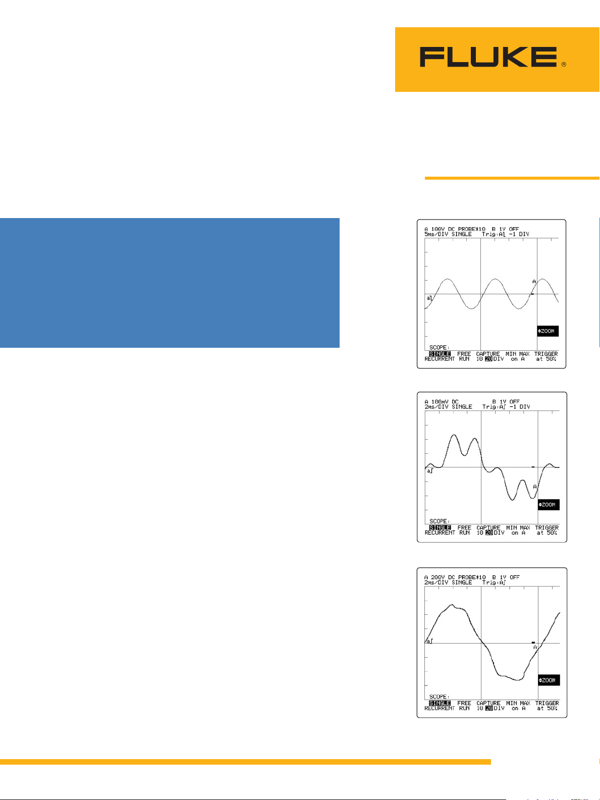
If you were to listen to an ordinary 60-cycle power line, you’d
hear a monotone hum. When
harmonics are present, you hear
a different tune, rich with high
notes. The problem is even more
evident when you look at the
waveform. A normal 60-cycle
power line voltage appears on
the oscilloscope as a near sine
wave (Figure 1). When harmonics are present, the waveform
is distorted (Figure 2A and 2B).
These waves are described as
non-sinusoidal. The voltage and
current waveforms are no longer
simply related-hence the term
“non-linear.”
Getting to the root of the
problem
Finding the problem is relatively
easy once you know what to look
for and where to look. Harmonics
symptoms are usually anything
but subtle. This application note
provides some basic pointers on
how to find harmonics and some
suggestions of ways to address
the problems they create.
Application Note
Figure 1. Near sine wave.
Figure 2A. Distorted current waveform.
Figure 2B. Distorted voltage waveform.
From the Fluke Digital Library @ www.fluke.com/library
Page 2
Sources of harmonics
Defining the problem
Harmonics are currents or voltages with frequencies that are
integer multiples of the fundamental power frequency. For
example, if the fundamental frequency is 60 Hz, then the second
harmonic is 120 Hz, the third is
180 Hz, etc.
Harmonics are created by nonlinear loads that draw current
in abrupt pulses rather than in
a smooth sinusoidal manner.
These pulses cause distorted
current wave shapes which in
turn cause harmonic currents to
flow back into other parts of the
power system.
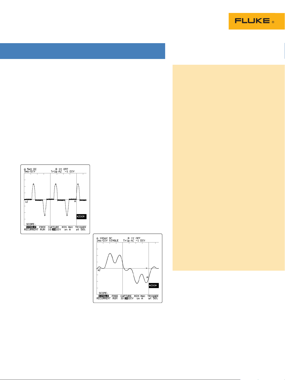
Figure 3A. Single-phase, non-linear load
current waveform.
The inside story
This phenomenon is especially
prevalent with equipment that
has diode-capacitor input power
supplies; i.e., personal computers, printers and medical test
equipment.
Electrically what happens is
the incoming ac voltage is diode
rectified and is then used to
charge a large capacitor. After
a few cycles, the capacitor is
charged to the peak voltage of
the sine wave (e.g., 170 V for a
120 V ac line). The electronic
equipment then draws current
from this high dc voltage to
power the rest of the circuit.
The equipment can draw the
current down to a regulated
lower limit. Typically, before
reaching that limit, the capacitor
is recharged to the peak in the
next half cycle of the sine wave.
This process is repeated over
and over. The capacitor basically
draws a pulse of current only
during the peak of the wave.
During the rest of the wave,
when the voltage is below the
capacitor residual, the capacitor
draws no current.
The diode/capacitor power
supplies found in office equipment are typically single-phase,
non-linear loads (Figure 3A).
In industrial plants, the most
common causes of harmonic currents are three-phase, non-linear
loads which include electronic
motor drives, and uninterruptible
power supplies (UPS) (Figure 3B).
Figure 3B. Three-phase, non-linear load
current waveform.
Voltage harmonics
The power line itself can be an indirect
source of voltage harmonics.
The harmonic current drawn by non-linear
loads acts in an Ohm’s law relationship
with the source impedance of the supplying
transformer to produce voltage harmonics.
Source impedance includes the supplying
transformer and branch circuit components.
For example, a 10 A harmonic current being
drawn from a source impedance of 0.1 W will
generate a harmonic voltage of 1.0 V.
Any loads sharing a transformer or a
branch circuit with a heavy harmonic load
can be affected by the voltage harmonics
generated.
The personal computer can be affected by
voltage harmonics. The performance of the
diode/capacitor power supply is critically
dependent on the magnitude of the peak
voltage. Voltage harmonics can cause “flat
topping” of the voltage waveform lowering
the peak voltage (see Figure 2B). In severe
cases, the computer may reset due to insufficient peak voltage.
In the industrial environment, the induction motor and power factor correction
capacitors can also be seriously affected by
voltage harmonics.
Power correction capacitors can form a
resonant circuit with the inductive parts
of a power distribution system. If the resonant frequency is near that of the harmonic
voltage, the resultant harmonic current
can increase substantially, overloading the
capacitors and blowing the capacitor fuses.
Fortunately, the capacitor failure detunes the
circuit and the resonance disappears.
2 Fluke Corporation Troubleshooting power harmonics
Page 3
Effects of harmonic currents
01
02
03
120 V Branch Circuits
208/480 Volt Transformer
Secondary
Primary
Neutral
A
B
C
Symptoms of harmonics usually
show up in the power distribution equipment that supports the
non-linear loads. There are two
basic types of non-linear loads:
single-phase and three-phase.
Single-phase, non-linear loads
are prevalent in offices, while
three-phase loads are widespread in industrial plants.
Each component of the power
distribution system manifests
the effects of harmonics a little
differently, yet all are subject to
damage and inefficient performance if not designed to handle
electronic loads.
Neutral conductors
In a three-phase, four-wire
system, neutral conductors can
be severely affected by nonlinear loads connected to the 120
V branch circuits. Under normal
conditions for a balanced linear
load, the fundamental 60 Hz
portion of the phase currents will
cancel in the neutral conductor.
In a four-wire system with
single-phase, non-linear loads,
certain odd-numbered harmonics called triplens—odd multiples
of the third harmonic: 3rd, 9th,
15th, etc—do not cancel, but
rather add together in the neutral
conductor. In systems with many
single-phase, non-linear loads,
the neutral current can actually
exceed the phase current. The
danger here is excessive overheating because, unlike phase
conductors, there are no circuit
breakers in the neutral conductor
to limit the current.
Excessive current in the neutral conductor can also cause
higher-than-normal voltage
drops between the neutral conductor and ground at the 120 V
outlet.
Circuit breakers
Common thermal-magnetic
circuit breakers use a bi-metallic
trip mechanism that responds to
the heating effect of the circuit
current. They are designed to
respond to the true-rms value of
the current waveform and will
trip when the trip mechanism
gets too hot. This type of breaker
has a good chance of protecting against harmonic current
overloads.
A peak-sensing, electronic trip
circuit breaker responds to the
peak of current waveform. As a
result, it won’t always respond
properly to harmonic currents.
Since the peak of the harmonic
current is usually higher than
normal, this type of circuit
breaker may trip prematurely at a
low current. If the peak is lower
than normal, the breaker may
fail to trip when it should.
Bus bars and
connecting lugs
Neutral bus bars and connecting
lugs are sized to carry the full
value of the rated phase current.
They can become overloaded
when the neutral conductors are
overloaded with the additional
sum of the triplen harmonics.
Electrical panels
Panels that are designed to carry
60 Hz currents can become
mechanically resonant to the
magnetic fields generated by
higher frequency harmonic
currents. When this happens,
the panel vibrates and emits a
buzzing sound at the harmonic
frequencies.
Telecommunications
Telecommunications systems
often give you the first clue to
a harmonics problem because
the cable can be run right next
to power cables. To minimize
the inductive interference from
phase currents, telecommunications cables are run closer to the
neutral wire.
Triplens in the neutral conductor commonly cause inductive
interference, which can be heard
on a phone line. This is often the
first indication of a harmonics
problem and gives you a head
start in detecting the problem
before it causes major damage.
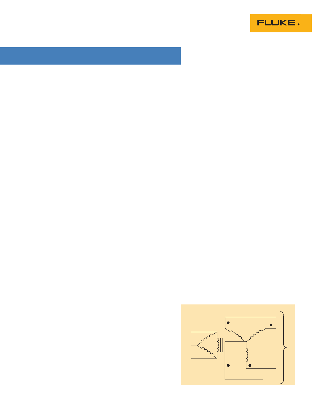
Transformer
Commercial buildings commonly
have a 208/120 V transformer
in a delta-wye configuration.
These transformers commonly
feed receptacles in a commercial building. Single-phase,
non-linear loads connected to
the receptacles produce triplen
harmonics, which add up in the
neutral. When this neutral current reaches the transformer, it is
reflected into the delta primary
winding where it causes overheating and transformer failures.
Another transformer problem
results from core loss and copper
loss. Transformers are normally
rated for a 60 Hz phase current
load only. Higher frequency harmonic currents cause increased
core loss due to eddy currents
and hysteresis, resulting in more
heating than would occur at the
same 60 Hz current.
These heating effects demand
that transformers be derated for
harmonic loads or replaced with
specially designed transformers.
3 Fluke Corporation Troubleshooting power harmonics
Page 4

Generators
Standby generators are subject
to the same kind of overheating problems as transformers.
Because they provide emergency
backup for harmonic producing
loads such as data processing
equipment, they are often even
more vulnerable. In addition to
overheating, certain types of
harmonics produce distortion at
the zero crossing of the current
waveform, which causes interference and instability for the
generator’s control circuits.
Classification of harmonics
Each harmonic has a name, frequency and sequence. The sequence refers
to phasor rotation with respect to the fundamental (F), i.e., in an induction
motor, a positive sequence harmonic would generate a magnetic field that
rotated in the same direction as the fundamental. A negative sequence harmonic would rotate in the reverse direction. The first nine harmonics along
with their effects are listed below:
Name F 2nd* 3rd 4th* 5th 6th* 7th 8th* 9th
Frequency 60 120 180 240 300 360 420 480 540
Sequence + — 0 + — 0 + — 0
*Even harmonics disappear when waves are symmetrical (typical for electrical circuits)
Sequence Rotation Effects (from skin effect, eddy currents, etc.)
Positive Forward Heating of conductors, circ uit breakers, etc.
Negative Reverse Heating as above plus motor problems
Zero** None Heating, plus add in neutral of 3-phase, 4-wire system
**Zero sequence harmonics (odd multiples of the 3rd) are called “Triplens” (3rd, 9th, 15th, 21st, etc.)
Finding harmonics
A harmonic survey will give you
a good idea if you have a problem and where it is located. Here
are a few guidelines to follow.
1. Load inventory. Make a
walking tour of the facility
and take a look at the types of
equipment in use. If you have
a lot of personal computers
and printers, adjustable speed
motors, solid-state heater
controls, and certain types of
fluorescent lighting, there’s a
good chance that harmonics
are present.
2. Transformer heat check.
Locate the transformers feeding those non-linear loads and
check for excessive heating.
Also make sure the cooling
vents are unobstructed.
3. Transformer secondary
current. Use a three-phase
true-rms power quality
analyzer to check transformer
currents.
Verify that the voltage rat-
•
ings for the clamp meter are
adequate for the transformer
being tested.
Measure and record the
•
transformer secondary currents in each phase and in
the neutral (if used).
Compare the kVA deliv-
•
ered to the load against the
nameplate rating. (If harmonic currents are present,
the transformer can overheat
even if the kVA delivered
is less than the nameplate
rating.)
Use the k-factor measure-
•
ment from a three-phase
analyzer to determine
de-rating or transformer
replacement.
Measure the frequency of
•
the neutral current. 180 Hz
would be a typical reading
for a neutral current consisting of mostly third harmonic.
4. Sub-Panel neutral current
check. Survey the sub-
panels that feed harmonic
loads. Measure the current
in each branch neutral and
compare the measured value
to the rated capacity for the
wire size used. Check the
neutral bus bar and feeder
connections for heating or
discoloration. A non-contact
infrared thermometer, like the
Fluke 61, is useful for detecting excessive overheating on
bus bars and connections.
5. Receptacle neutral-to-
ground voltage check.
Neutral overloading in
receptacle branch circuits
can sometimes be detected
by measuring the neutralto-ground voltage at the
receptacle.
Measure the voltage when
•
the loads are on. Two volts
or less is about normal.
Higher voltages can indicate
trouble depending on the
length of the run, quality of
connections, etc. Measure
the frequency. A frequency
of 180 Hz would suggest
a strong presence of harmonics, while 60 Hz would
suggest that the phases are
out of balance. Pay special
attention to under carpet
wiring and mod-ular office
panels with integrated
wiring that uses a neutral
shared by three-phase
conductors.
Because the typical loads in
•
these two areas are computer and office machines,
they are often trouble spots
for overloaded neutrals.
4 Fluke Corporation Troubleshooting power harmonics
Page 5

Troubleshooting tools
To determine whether you have
a harmonics problem you need to
measure the true-rms value and
the instantaneous peak value
of the wave shape. For single
applications, you need either a
clamp meter like the Fluke 335,
336 or 337 or a multimeter like
those in the Fluke 80, 170 and
180 Series that makes true-rms
measurements. For three-phase
applications, you’ll need a power
quality analyzer like the Fluke
430 Series.
“True-rms” refers to the
root-mean-square, or equivalent heating value of a current
or voltage wave shape. “True”
distinguishes the measurement
from those taken by “average
responding” meters. The vast
majority of low-cost, portable
meters are average responding.
These instruments give correct
readings for pure sine waves
only and will typically read low
by as much as 50 percent when
confronted with a distorted
current waveform. True-rms
meters give correct readings
for any wave shape within the
instrument’s crest factor and
bandwidth specifications.
Crest factor
The crest factor of a waveform is
the ratio of the peak value to the
rms value. For a sine wave, the
crest factor is 1.414. A true-rms
meter will have a crest factor
specification. This spec relates to
the level of peaking that can be
measured without errors.
A quality true-rms handheld
digital multimeter has a crest
factor of 3.0 at full scale. This
is more than adequate for most
power distribution measurements. At half scale the crest
factor is double. For example, the
Fluke 187 DMM has a crest factor
spec of up to 3.0 when measuring 400 V ac and a crest factor
of up to 6.0 when measuring
200 V ac.
Using a true-rms meter with a
“Peak” function—like the Fluke
187—the crest factor can be
Multimeter performance comparison average
responding vs. true-rms
Meter Type
Measuring
easily calculated. A crest factor
other than 1.414 indicates the
presence of harmonics. In typical
single-phase cases, the greater
the difference from 1.414, the
higher the harmonic content. For
voltage harmonics, the typical crest factor is below 1.414;
i.e., a “flat top” waveform. For
single-phase current harmonics,
the typical crest factor is much
higher than 1.414.
Three-phase current waveforms often exhibit a “double
hump” waveform, therefore the
crest factor comparison method
should not be applied to threephase load current.
After you’ve determined that
harmonics are present, you can
make a more in-depth analysis
of the situation with a harmonic
analyzer such as the Fluke 43B
Power Quality Analyzer.
Circuit
Sine Wave
Response*
Square Wave
Response*
Distorted Wave
Response*
5 Fluke Corporation Troubleshooting power harmonics
Average
Responding
True-rms RMS Calculating
*Within multimeter’s bandwidth and crest factor specifications.
Rectified
Average x 1.1
converter. Cal-
culates heating
value.
Correct 10 % high Up to 50 % low
Correct Correct Correct
Page 6

Solving the problem
The following are suggestions
of ways to address some typical harmonics problems. Before
taking any such measures you
should call a power quality
expert to analyze the problem
and design a plan tailored to
your specific situation.
In overloaded neutrals
In a three-phase, four-wire
system, the 60 Hz portion of the
neutral current can be minimized
by balancing the loads in each
phase. The triplen harmonic
neutral current can be reduced
by adding harmonic filters at the
load. If neither of these solutions
is practical, you can pull in extra
neutrals —ideally one neutral for
each phase—or you can install
an oversized neutral shared by
three phase conductors.
In new construction, under
carpet wiring and modular office
partitions wiring should be
specified with individual neutrals
and possibly an isolated ground
separate from the safety ground.
Derating transformers
One way to protect a transformer from harmonics is to limit
the amount of load placed on
it. This is called “derating” the
transformer. The most rigorous
derating method is described
in ANSI/IEEE standard C57.110-
1986. It is somewhat impractical
because it requires extensive
loss data from the transformer
manufacturer plus a complete
harmonic spectrum of the load
current.
The Computer & Business
Equipment Manufacturers Association has recommended a second
method that involves several
straightforward measurements
that you can get with commonly available test equipment.
It appears to give reasonable
results for 208/120 V receptacle
transformers that supply low
frequency odd harmonics (third,
fifth, seventh) commonly generated by computers and office
machines operating from singlephase branch circuits.
Derating factor
To determine the derating factor for the transformer, take the peak and truerms current measurements for the three phase conductors. If the phases are not
balanced, average the three measurements and plug that value into the following formula:
HDF = Harmonic derating factor
= (1.414)(true-rms phase current)
This formula generates a value between 0 and 1.0, typically between 0.5
and 0.9. If the phase currents are purely sinusoidal (undistorted) the instantaneous peaks are 1.414 times the true-rms value and the derating factor is 1.0.
If that is the case no derating is required.
However, with harmonics present the transformer rating is the product of the
nameplate kVA rating times the HDF.
kVA derated = (HDF) x (kVA nameplate)
For example: 208/120 Y transformer rated at 225 kVA:
Load currents were measured with
a Fluke Model 87 and an 80i-600 ac
current probe to produce the following results:
(Instantaneous peak phase current)
Conductor
name
01 410 A 804 A
02 445 A 892 A
03 435 A 828 A
True-rms
current amps
Instantaneous
peak current
6 Fluke Corporation Troubleshooting power harmonics
I phase avg. = 410 + 445 + 435 = 430 A
3
I pk avg. = 804 + 892 + 828 = 841 A
3
HDF = (1.414) (430) = 72.3 %
841
The results indicate that with the level of harmonics present the transformer
should be derated to 72.3 % of its rating to prevent overheating.
Page 7

Work safely
The high voltage and current
present in electrical power
systems can cause serious
injury or death by electrocution. Consequently, only trained,
experienced electricians who
have knowledge of electrical systems in general and the
equipment under test should
perform testing and modification
of electrical systems.
Fluke cannot anticipate all
possible precautions that you
must take when performing the
measurements described here.
At a minimum, however, you
should:
Use appropriate safety equip-
•
ment such as safety glasses,
insulating gloves, insulating
mats, etc.
Be sure that all power has
•
been turned off, locked out,
and tagged in any situation
where you will be in direct
contact with circuit components. Be certain that the
power can’t be turned on by
anyone but you.
Read and understand all of
•
the applicable manuals before
using the application information in this application note.
Take special note of all safety
precautions and warnings in
the instruction manuals.
This article is a general guide to
understanding harmonics. It is
not intended to substitute for the
services of a professional electrical systems consultant. Before
you take any measures to diagnose or address your potential
harmonics problems, you should
have your operation thoroughly
analyzed by a professional electrical engineer.
Situation
A modern office building dedicated primarily to computer
software development contained
a large number of personal computers and other electronic office
equipment. These electronic
loads were fed by a 120/208 V
transformer configured with a
delta primary and a wye secondary. The PCs were fairly well
distributed throughout the building, except for one large room
that contained several machines.
The PCs in this room, used exclusively for testing, were served by
several branch circuits.
The transformer and main
switch gear were located in a
ground floor electrical room.
Inspection of this room immediately revealed two symptoms of
high harmonic currents:
The transformer was generat-
•
ing a substantial amount of
heat.
Case study
The main panel emitted an
•
audible buzzing sound. The
sound was not the chatter
commonly associated with
a faulty circuit breaker, but
rather a deep resonant buzz
that indicated the mechanical
parts of the panel itself were
vibrating.
Ductwork installed directly over
the transformer to carry off some
of the excess heat kept the room
temperature within reasonable
limits.
Conductor name
Phase 1 410 328 804
Phase 2 445 346 892
Phase 3 435 355 828
Neutral 548 537 762
True-rms multimeter
Defining the problem
Transformer – Current measurements (see Table 1) were
taken on the neutral and on
each phase of the transformer
secondary using both a true-rms
multimeter and an averageresponding unit. A 600 A
clamp-on current transformer
accessory was connected to each
meter to allow them to make
high current readings. The current waveshapes are shown in
Figures 4 and 5.
(amps)
Average responding
multimeter (amps)
Instantaneous peak
current (amps)
7 Fluke Corporation Troubleshooting power harmonics
Page 8

The presence of harmonics
was obvious by comparison of
phase current and neutral current measurements. As Table 1
shows, the neutral current was
substantially higher than any of
the phase currents, even though
the phase currents were relatively
well balanced. The averageresponding meter consistently
took readings approximately 20
percent low on all the phases.
Its neutral current readings were
only 2 percent low.
The waveforms explain the
Figure 4. Phase current.
discrepancy. The phase currents
were badly distorted by large
amounts of third harmonic current, while the neutral current
was nearly a pure sinewave at
the third harmonic frequency.
The phase current readings
listed in Table 1 demonstrate
clearly why true-rms measurement capability is required to
accurately determine the value of
harmonic currents.
The next step was to calculate
the “harmonic derating factor” or
HDF (Refer to “Derating transformers” section on page 6.)
Figure 5. Neutral current.
The results indicated that,
with the level of harmonics
present, the transformer should
be derated to 72.3 percent of
conductor
its nameplate rating to prevent
overheating. In this case the
transformer should be derated
to 72.3 percent of its 225 kVA
rating, or derated to 162.7 kVA.
The actual load was calculated to be 151.3 kVA. Although
that figure was far less than the
nameplate rating, the transformer
was operating close to its derated
capacit y.
Subpanel—Next a subpanel
which supplied branch circuits
for the 120 V receptacles was
examined. The current in each
neutral was measured and
recorded (see Table 2).
When a marginal or overloaded conductor was identified,
the associated phase currents
and the neutral-to-ground
voltage at the receptacle were
also measured. When a check
of neutral #6 revealed 15 A in
a conductor rated for 16 A, the
Table 2. Subpanel branch circuit neutral
currents.
phase currents of the circuits
8 Fluke Corporation Troubleshooting power harmonics
Neutral
number
01 5.0
02 11. 3
03 5.0
04 13.1
05 12 .4
06 15.0*
07 1.8
08 11.7
09 4.5
10 11. 8
11 9.6
12 11 .5
13 11. 3
14 6.7
15 7.0
16 2.3
17 2.6
Current
(amps)
(#25, #27, and #29) that shared
that neutral were also measured
(Table 3). Note that each of the
phase currents of these three
branch circuits was substantially less than 15 A, and also
the same phase conductors had
significant neutral-to-ground
voltage drops.
In the branch circuits which
had high neutral current, the
relationship between the neutral
and the phase currents was
similar to that of the transformer
secondary. The neutral current was higher than any of the
associated phase currents. The
danger here is that the neutral
conductors could become overloaded and not offer the warning
signs of tripped circuit breakers.
Recommendations
1. Refrain from adding addi-
tional loads to the receptacle
transformer unless steps are
taken to reduce the level of
harmonics.
2. Pull in extra neutrals to the
branch circuits that are heavily loaded.
3. Monitor the load currents on a
regular basis using true-rms
measuring test equipment.
Circuit
number
25 7.8 3.75 V
27 9.7 4.00 V
29 13.5 8.05 V
Table 3. Phase currents and neutral-to-ground voltage for neutral #06.
Phase
current
(amps)
Neutral-to-ground voltage
drop at receptacle
Fluke. Keeping your world
up and running.
Fluke Corporation
PO Box 9090, Everett, WA 98206 U.S.A.
Fluke Europe B.V.
PO Box 1186, 5602 BD
Eindhoven, The Netherlands
For more information call:
In the U.S.A. (800) 443-5853 or
Fax (425) 446-5116
In Europe/M-East/Africa +31 (0) 40 2675 200 or
Fax +31 (0) 40 2675 222
In Canada (800)-36-FLUKE or
Fax (905) 890-6866
From other countries +1 (425) 446-5500 or
Fax +1 (425) 446-5116
Web access: http://www.fluke.com
©2003-2009 Fluke Corporation.
Specifications subject to change without notice.
Printed in U.S.A. 6/2009 1260362K A-EN-N
Modification of this document is not permitted
without written permission from Fluke Corporation.
®
 Loading...