

Fluke 78 Service Manual

78
®
Automotive Meter
Service Manual
For IEC 61010 CAT II Meters Only
PN 666617
November 1998
© 1998 Fluke Corporation, All rights reserved. Printed in U.S.A.
All product names are trademarks of their respective companies.

LIMITED WARRANTY & LIMITATION OF LIABILITY
Fluke Corporation (Fluke) warrants this product to be free from defects in material and workmanship under normal use and service for the life
of the product. This warranty extends only to the original buyer or end-user customer of a Fluke authorized reseller, and does not apply to
fuses, batteries or to any product which, in Fluke’s opinion, has been misused, altered, neglected or damaged by accident or abnormal
conditions of operation or handling. Fluke warrants that software will operate on appropriate Fluke instruments substantially in accordance
with its functional specifications for 90 days and that it has been properly recorded on non-defective media. Fluke does not warrant that
software will be error free or operate without interruption.
Fluke authorized resellers shall extend this warranty on new and unused products to end-user customers only but have no authority to
extend a greater or different warranty on behalf of Fluke.
Fluke’s warranty obligation is limited, at Fluke’s option, to refund of the purchase price, or free of charge repair or replacement of a defective
product which is returned to an authorized Fluke Service Center within the warranty period.
To obtain warranty service, contact your nearest Fluke Service Center or send the product, with a description of the difficulty, postage and
insurance prepaid (FCA Destination), to the nearest Fluke Service Center. Fluke assumes no risk for damage in transit. Following warranty
repair, the product will be returned to Buyer, transportation prepaid (FCA Destination). If Fluke determines that the failure was caused by
misuse, alteration, accident or abnormal condition of operation or handling, Fluke will provide an estimate of repair costs and obtain
authorization before commencing the work. Following repair, the product will be returned to the Buyer transportation prepaid and the Buyer
will be billed for the repair and return transportation charges (FCA Shipping Point).
Warranty service is available outside the United States only if product was purchased through a Fluke Authorized Sales Outlet in the country
of use or the applicable Fluke international price was paid. Product transported from the United States for which the applicable Fluke
international price was not paid must be returned to the U.S. to receive warranty service, at the shipment expense and risk of Buyer. Fluke
reserves the right to invoice Buyer for importation costs of repair/replacement parts when product purchased in one country is submitted for
repair in another country.
THIS WARRANTY IS PURCHASER’S SOLE AND EXCLUSIVE REMEDY AND IS IN LIEU OF ALL OTHER WARRANTIES, EXPRESS OR
IMPLIED, INCLUDING BUT NOT LIM ITED TO ANY IMPLIED WARRANTY OF MERCHANTABILITY OR FITNESS FOR A PARTICULAR
PURPOSE. FLUKE SHALL NOT BE LIABLE FOR ANY SPECIAL, INDIRECT, INCIDENTAL OR CONSEQUENTIAL DAMAGES OR
LOSSES, INCLUDING LOSS OF DATA, WHETHER ARI SI NG FROM BREACH OF WARRANTY OR BASED ON CONTRACT, TORT,
RELIANCE OR ANY OTHER THEORY.
Since some countries or states do not allow limitation of the term of an implied warranty, or exclusion or limitation of incidental or
consequential damages, the limitations and exclusions of this warranty may not apply to every buyer. If any provision of this Warranty is held
invalid or unenforceable by a court of competent jurisdiction, such holding will not affect the validity or enforceability of any other provision of
this warranty.
Fluke Corporation Fluke Europe B.V.
P.O. Box 9090 P.O. Box 1186
Everett WA 5602 B.D. Eindhoven
98206-9090 The Netherlands

Safety Information
This meter complies with EN 61010-1:1993, ANSI/ISA S82.01-1994 and CAN/CSA
C22.2 No. 1010.1-92 Overvoltage Category II. Use the meter only as specified in the
Users Manual, otherwise the protection provided by the meter may be impaired.
A Warning identifies conditions and actions that pose hazards to the user; a Caution
identifies conditions and actions that might damage the meter. International electrical
symbols used on the meter are shown below.
W Warning
To avoid possible electric shock or personal inj ury:
• Do not use the meter if it is damaged. Bef ore use, inspect the
case for cracks or missing plastic. Pay particular att ent ion to the
insulation surrounding the connectors.
• Always turn off power to the circui t before cutting, unsoldering,
or breaking the circuit. Small amounts of current can be
dangerous.
• Inspect the test leads for damaged insulat ion or exposed metal.
Check test lead continuity. Replace damaged leads.
• To avoid damage or injury, never use the meter on unprotected
circuits that exceed 4800 volt-amps.
• Do not use the meter if it operates abnormally. Prot ect i on may be
impaired. When in doubt, have the meter serviced.
• Do not operate the meter around explosive gas, vapor or dust.
• Do not apply more than 300 V dc or ac rms (sine) between
terminals or between any terminal and earth ground.
• Before each use, verify the meter’s operation by measuring a
known voltage.
• When servicing the meter, use only specified replacement part s.
• Use caution when working above 30 V ac rms, 42 V ac peak, or 60
V dc. Such voltages pose a shock hazard.
• Keep your fingers behind the finger guards on the probe when
making measurements.
• Connect the common test lead before connecting the l i ve test
lead. Disconnect the live test lead first.
• Remove test leads from the meter before opening the case.
• Use only a single 9 V battery, properly installed in the meter case,
to power the meter.
• Follow all equipment safety procedures.
• Before measuring current, check the meter’s fuses (see “How to
Test the Fuse”).
• Never touch the probe to a voltage source when the test l eads are
plugged into the 10 A input jack.
• Always use clamp-on probes (dc current clamps) when
measuring current exceeding 10 A.
• DO NOT connect thermocouple to voltages exceeding 30 V.
• Always use a high voltage probe to measure voltage if peak
voltage might exceed 300 V.
• To avoid false readings, which could l ead t o possi ble electric
shock or personal injury, replace the meter’s battery as soon as
the low battery indicator (N) appears.
• To avoid fire hazard, only use a fuse identical in type, voltage
rating, and current rating to that speci f ied on the fuse rating label
located on the case bottom.
• Do not operate the meter if it is di sassembled. Always operate the
meter with the case top and bottom properly assembled.
Disassembly procedures and warnings are in the 78 Automotive
Service Manual. Service procedures are for qualified personnel
only.
Caution
To avoid possible damage to the meter or to equipment under
test:
• Disconnect the power to the circuit under t est and discharge all
high voltage capacitors before testing resi stance, continuity or
diodes.
• Use the proper function and range for your measurement
applications.
• When measuring current, turn off circuit power before connect i ng
the meter in the circuit. Remember to place the met er i n seri es
with the current.
Symbols
Symbol Meaning
Important information. See manual.
Ground
Fuse
Double insulation (Protection Class II)
Conforms to European Union directives

Table of Contents
Chapter Title Page
1 Introduction and Specifications.......................................................... 1-1
1-1. Introduction ........................................................................................... 1-3
1-2. Organization of the Service Manual ..................................................... 1-3
1-3. Conventions ........................................................................................... 1-4
1-4. Specifications ........................................................................................ 1-4
2 Theory of Operation............................................................................. 2-1
2-1. Introduction ........................................................................................... 2-3
2-2. Functional Block Description ............................................................... 2-3
2-3. Circuit Descriptions .............................................................................. 2-4
2-4. Input Overload Protection ................................................................. 2-4
2-5. Rotary Knob Switch ......................................................................... 2-4
2-6. Input Signal Conditioning Circuits .................................................. 2-4
2-7. Volts Functions ............................................................................ 2-4
2-8. Ohms Function ............................................................................ 2-5
2-9. Continuity .................................................................................... 2-6
2-10. Temperature Function .................................................................. 2-6
2-11. Diode Test Function .................................................................... 2-7
2-12. RPM Function .............................................................................. 2-7
2-13. Current Function .......................................................................... 2-7
2-14. Analog Section of Integrated Multimeter IC (U1) .......................... 2-7
2-15. Frequency Measurements ............................................................ 2-9
2-16. Dwell and Duty Cycle Measurements ......................................... 2-9
2-17. Microcomputer Control .................................................................... 2-9
2-18. Peripherals to U1 ............................................................................... 2-9
2-19. AC Buffer ..................................................................................... 2-9
2-20. AC converter ................................................................................. 2-9
2-21. Active Filter .................................................................................. 2-9
2-22. A/D Converter .............................................................................. 2-9
2-23. Beeper ........................................................................................... 2-10
2-24. Power Supply ................................................................................ 2-10
2-25. Display .............................................................................................. 2-10
3 Maintenance ......................................................................................... 3-1
i

78
Service Manual
3-1. Introduction ........................................................................................... 3-3
3-2. Recommended Equipment .................................................................... 3-3
3-3. Operator Maintenance ........................................................................... 3-3
3-4. Case Disassembly ............................................................................. 3-3
3-5. Battery Replacement ......................................................................... 3-3
3-6. Fuse Test ........................................................................................... 3-5
3-7. Fuse Replacement ............................................................................. 3-5
3-8. Circuit Assembly Removal ............................................................... 3-5
3-9. Display Access .................................................................................. 3-5
3-10. Cleaning ................................................................................................. 3-7
3-11. Performance Tests ................................................................................. 3-7
3-12. Setup .................................................................................................. 3-7
3-13. Display Test ...................................................................................... 3-8
3-14. DC Voltage Test ................................................................................ 3-8
3-15. AC Voltage Test ................................................................................ 3-9
3-16. Frequency Test .................................................................................. 3-9
3-17. Frequency, Dwell, and Duty Cycle Trigger Level Test .................... 3-10
3-18. RPM Test .......................................................................................... 3-10
3-19. Ohms Test ......................................................................................... 3-11
3-20. Continuity Test .................................................................................. 3-11
3-21. Diode Test ......................................................................................... 3-12
3-22. DC and AC Current Test ................................................................... 3-12
3-23. Temperature Test .............................................................................. 3-12
3-24. RPM80 Inductive Pickup Test (Optional Accessory) ....................... 3-14
3-25. Calibration ............................................................................................. 3-17
3-26. Troubleshooting .................................................................................... 3-18
3-27. Surface Mount Assemblies ............................................................... 3-18
3-28. Power Supply Related Troubleshooting ........................................... 3-18
3-29. Common (Shunt) Regulator Troubleshooting .................................. 3-19
3-30. Vdd (Series) Regulator Troubleshooting .......................................... 3-20
4 List of Replaceable Parts .................................................................... 4-1
4-1. Introduction ........................................................................................... 4-3
4-2. How to Obtain Parts .............................................................................. 4-3
4-3. Manual Status Information .................................................................... 4-3
4-4. Service Centers ...................................................................................... 4-4
4-5. Parts Lists .............................................................................................. 4-4
5 Schematic Diagrams............................................................................ 5-1
ii

List of Tables
Table Title Page
1-1. Specifications........................................................................................................... 1-5
2-1. Typical Voltage Levels and Tolerance (Referenced to Common).......................... 2-10
3-1. Recommended Test Equipment............................................................................... 3-4
3-2. DC Voltage Test ...................................................................................................... 3-8
3-3. AC Voltage Test ...................................................................................................... 3-9
3-4. Frequency Test......................................................................................................... 3-9
3-5. Frequency, Dwell, and Duty Cycle Trigger Level Test .......................................... 3-10
3-6. RPM Test................................................................................................................. 3-10
3-7. Resistance Test ........................................................................................................ 3-11
3-8. Continuity Test ........................................................................................................ 3-11
3-9. Diode Test................................................................................................................ 3-12
3-10. DC and AC Current Test ......................................................................................... 3-12
3-11. Functional Description of Power Supply Components ........................................... 3-19
3-12. Voltage Levels......................................................................................................... 3-19
4-1. Fluke 78 Final Assembly......................................................................................... 4-5
4-2. A1 Main PCA .......................................................................................................... 4-7
5-1. Signal Abbreviations ............................................................................................... 5-3
iii

78
Service Manual
iv

List of Figures
Figure Title Page
2-1. Block Diagram......................................................................................................... 2-3
2-2. 4 V Range Simplified Schematic............................................................................. 2-5
2-3. 400 Ohm Range Simplified Schematic ................................................................... 2-6
2-4. A/D Converter ......................................................................................................... 2-8
3-1. Disassembled Fluke 78............................................................................................ 3-6
3-2. Display.....................................................................................................................3-8
3-3. Ambient Temperature Lag Bath.............................................................................. 3-13
3-4. Setup for RPM80 Inductive Pickup Test................................................................. 3-15
3-5. Typical Waveforms for Inductive Pickup Test ....................................................... 3-16
3-6. Calibration Adjustment Point.................................................................................. 3-17
4-1. Fluke Final Assembly............................................................................................. 4-6
5-1. A1 Main PCA .......................................................................................................... 5-5
v

78
Service Manual
vi

Chapter 1
Introduction and Specifications
Title Page
1-1. Introduction............................................................................................ 1-3
1-2. Organization of the Service Manual ...................................................... 1-3
1-3. Conventions............................................................................................ 1-4
1-4. Specifications......................................................................................... 1-4
1-1

78
Service Manual
1-2

1-1. Introduction
This Service Manual provides information on maintaining, troubleshooting, and
repairing the Fluke 78 Automotive Meter. This information includes the following:
• Specifications
• Theory of operation
• Calibration
• Performance testing and troubleshooting procedures
• Replacement parts lists
• Schematic diagrams
A meter under warranty will be promptly repaired or replaced (at Fluke’s option) and
returned at no charge. See the registration card for warranty terms. If the warranty has
expired, the meter will be repaired and returned for a fixed fee. Contact the nearest
Service Center for information and prices. A list of U.S. and International Fluke
telephone numbers is included at the end of Chapter 4 of this manual.
Introduction and Specifications
Introduction
1
1-2. Organization of the Service Manual
This service manual has the following five chapters.
Chapter 1. Introduction and Specifi cat ions
Chapter 1 describes the Service Manual, explains special terminology and conventions,
and provides complete meter specifications.
Chapter 2. Theory of Operation
Chapter 2 treats the meter’s circuitry as functional blocks, with a description of each
block’s role in overall operation. A detailed circuit description is then given for each
block. These descriptions explain operation to the component level and support the
troubleshooting and repair procedures in Chapter 3.
Chapter 3. Maintenance
Chapter 3 provides maintenance information, detailed repair procedures to the
component level, and performance tests. Troubleshooting and repair procedures rely on
the Theory of Operation presented in Chapter 2 and the Schematic Diagrams in Chapter
5.
Chapter 4. List of Replaceable Parts
Chapter 4 provides parts lists and information on how and where to order parts.
Chapter 5. Schematic Diagrams
Chapter 5 provides schematic diagrams for all assemblies and a list of mnemonic
definitions to aid in identifying signal name abbreviations.
1-3

78
Service Manual
1-3. Conventions
1-4. Specifications
The following conventions are used in this manual:
• Printed Circuit Assembly (PCA)
A "pca" is a printed circuit board and its attached parts.
• Circuit Nodes
A pin or connection on a component is specified by a dash (-) and number following
the component reference designator.
For example, pin 19 of U30 would be U30-19.
• User Notation
Switch positions, input terminals, and display annunciators are usually shown as
they appear on the meter.
Mnemonics used in the meter circuit descriptions correspond to those on the
schematic diagrams in Chapter 5.
Specifications for the Fluke 78 are in Table 1-1. Accuracy is specified for a period of one
year after calibration, at 18°C to 28°C (64°F to 82°F) with relative humidity to 95%. AC
conversions are ac-coupled, average responding, and calibrated to the rms value of a sine
wave input.
Accuracy Specifications are given as:
±([% of reading] + number of least significant digits)
1-4

Introduction and Specifications
Specifications
Table 1-1. Specifications
Maximum Voltage Between
any Terminal and Earth
Ground
Fuse Protection 15 A 600 V FAST Fuse
Display Digital: 4000 counts, updates 4/s
Operating Temperature 0°C to 55°C (32°F to 131°F)
Storage Temperature 40°C to 60°C (40°F to 140°F)
Temperature Coefficient 0.1 x (specified accuracy) per °C ambient
Relative Humidity 0% to 95%, to 30°C (86°F)
Altitude
Electromagnetic Compatibility
Battery Type 9 V, NEDA 1604 or 6F22 or 006P
Battery Life Alkaline: 500 hrs (typical)
Continuity Beeper 4096 Hz
Shock, Vibration Per MILT28800E for a Type III, Class 3 Style D, Instrument
Size (HxWxL) 1.12 in x 2.95 in x 6.55 in
Weight 12 oz (340g)
Safety Complies with EN 610101:1993, ANSI/ISA S82.011994 and
Safety Approvals CSA Certified, TUV Product Service licensed, UL
EMI Regulation Complies with FCC Part 15, Class B, VDE 0871B, Vfg. 2431991
Inductive Pickup Input: Magnetic field from spark plug
Thermocouple Type: K (Chromel vs. Alumel)
MIN MAX Recording Accuracy: Specified accuracy of measurement function ±16 digits for
300 V
Bar Graph: 64 segments, update rate 40/s
Frequency: 9,999 counts, updates 3/s
(<18°C or >28°C). Temperature, 0.04% + 0.1°C per °C
0% to 75%, to 40°C (104°F)
0% to 45%, to 55°C (131°F)
2000 meters maximum
In an RF field of 1 V/m on all ranges and functions:
Total Accuracy = Specified Accuracy +0.7% or range
Performance above 1 V/m is not specified.
Carbonzinc: 300 hrs (typical)
(2.8 cm x 7.5 cm x 16.6 cm)
CAN/CSA C22.2 No. 1010.192 Overvoltage Category II.
Output: Pulse to trigger Fluke 78
(Fluke 80PK1) Not suitable for immersion in liquid. Accuracy: ±1.1°C
(2°F) between 0°C to 260°C (32°F-500°F).
Typically within 1.1°C (2°F) of NBS tables for temperatures between
40°C (40°F) to 0°C (32°F).
Temperature Range: 40°C to 260°C.
(40°F to 500°F). Above 260°C (500°F), toxic gas might be emitted.
NOTE: The temperature range is primarily a function of the thermal
limitations of the thermocouple's insulation.
Cable Insulation: Teflon
changes > 200 ms in duration (±52 digits in 400 J).
Nominal response time (5 to 100% of range) 100 ms to 80%
1
1-5
78
Service Manual
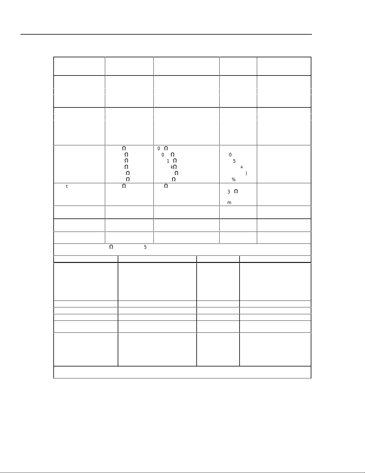
Table 1-1. Specifications (cont)
Function Range Resolution Accuracy Burden Voltage
(Typical)
AC Volts* 4.000 V 0.001 V ± (2.5%+2)
(45 Hz to 1 kHz) 40.00 V 0.01 V ± (2.5%+2) N/A
300.0 V 0.1 V ± (2.5%+2)
300 V 1 V ± (2.5%+2)
To 20 kHz -- -- ± 1.5 dB typical
DC Volts* 400.0 mV 0.1 mV ± (0.3%+5)
4000 mV 1 mV ± (0.3%+1)
4.000 V 0.001 V ± (0.3%+1)
40.00 V 0.01 V ± (0.3%+1) N/A
300.0 V 0.1 V ± (0.3%+1)
300 V 1 V ± (0.3%+1)
Resistance 400.0
Continuity 400.0
Diode Test 2.500 V 0.001 V ± 2% typical Open circuit voltage
AC Current
(45 Hz to 1 kHz)
DC Current 4.000 A
* Input impedance: 10 MJ (nominal), < 150 pF.
** 10 A continuous, 20 A overl oad f or 30 seconds maximum.
J
J
4.000 k
J
40.00 k
J
400.0 k
J
4.000 M
J
40.00 M
J
10.00 A** 0.01 A ± (2.5%+2) 0.03 V/A
10.00 A**
J
0.1
0.001
00.01 k
000.1 k
0.001 M
0.01 M
J
0.1
0.001 A
0.01 A
± (0.5%+2) N/A
J
J
J
J
J
± (0.5%+1)
± (0.5%+1)
± (0.5%+1)
± (0.5%+1)
± (1%+3)
Beeper on @
<30 J for
short of
1 ms or longer
± (1.0%+5)
± (1.0%+2)
Open circuit voltage
< 1.5 V
< 3.3 V
0.03 V/A
0.03 V/A
Function Range Resolution Accuracy
Frequency 99.99 0.01 Hz ± 0.01%+2)
(1 Hz to 20 kHz) 999. 9 0.1 Hz ± (0.01%+2)
9.999 kHz 0.001 kHz ± (0.01%+2)
20.00 kHz 0.01 kHz ± (0.01%+2)
(107 V-Hz maximum) >20.00 kHz to 99.99 kHz 0.01 kHz Usable
500.0 kHz 0.1 kHz Usable
RPM 1 70-7,000 RPM (usable to 9,999) 1RPM ± (0.2% + 2)
RPM 1 120-7,000 RPM (usable to 9,999) 1RPM ± (0.2% + 2)
Dwell Angle 0-120 1 degree ± 2 degrees
Duty Cycle 0.0-99.9%
(1 Hz to 20 kHz, pulse widt h> 5 µs)
Temperature* -40 to +999°C @ >20°C ambient,
to +980°C below 20°C ambient
* When measuring temperature, the accuracy of the system is the combined accuracy of the met er and the
thermocouple.
0.1% ± (0.2% per kHz +0.1%)
(for rise time <1 µs)
1 degree ± (0.3%+6°C) @ -40 to -20°C
± (0.3%+4°C) @ -20 to 0°C
± (0.3%+3°C) @ 0 to 170°C
± (0.3%+5°C) @ 170 to 260°C
± (0.3%+6°C) @ 260 to 700°C
± (0.3%+7°C) @ 700 to 999°C
1-6

Introduction and Specifications
Table 1-1 Specifications (cont)
Frequency Counter Sensitivity and Trigger Level
Input Range Minimum Sensitivity
(Rms Sine Wave)
1 Hz to 5 Hz 5 Hz to 20 kHz
400.0 mV dc -- -- 400 mV
4000 mV dc -- -- 400 mV
4.00 V 0.7 V 0.3 V 1.7 V
40.00 V 7 V 3 V 4 V
300.0 70 V 30 V 40 V
Approximate Trigger Level
(DC Volts Function)
Specifications
1
1-7

78
Service Manual
1-8

Chapter 2
Theory of Operation
Title Page
2-1. Introduction............................................................................................ 2-3
2-2. Functional Block Description................................................................. 2-3
2-3. Circuit Descriptions................................................................................ 2-4
2-4. Input Overload Protection.................................................................. 2-4
2-5. Rotary Knob Switch........................................................................... 2-4
2-6. Input Signal Conditioning Circuits.................................................... 2-4
2-7. Volts Functions.............................................................................. 2-4
2-8. Ohms Function .............................................................................. 2-5
2-9. Continuity...................................................................................... 2-6
2-10. Temperature Function.................................................................... 2-6
2-11. Diode Test Function ...................................................................... 2-7
2-12. RPM Function................................................................................ 2-7
2-13. Current Function............................................................................ 2-7
2-14. Analog Section of Integrated Multimeter IC (U1) ............................ 2-7
2-15. Frequency Measurements.............................................................. 2-9
2-16. Dwell and Duty Cycle Measurements........................................... 2-9
2-17. Microcomputer Control ..................................................................... 2-9
2-18. Peripherals to U1................................................................................ 2-9
2-19. AC Buffer ...................................................................................... 2-9
2-20. AC converter.................................................................................. 2-9
2-21. Active Filter................................................................................... 2-9
2-22. A/D Converter ............................................................................... 2-9
2-23. Beeper............................................................................................ 2-10
2-24. Power Supply................................................................................. 2-10
2-25. Display............................................................................................... 2-10
2-1

78
Service Manual
2-2
 Loading...