

Page 1

7526A
Precision Process Calibrator
March 2013
© 2013 Fluke Corporation. All rights reserved. Specifications are subject to change without notice.
All product names are trademarks of their respective companies.
Calibration Manual
Page 2

LIMITED WARRANTY AND LIMITATION OF LIABILITY
Each Fluke product is warranted to be free from defects in material and workmanship under
normal use and service. The warranty period is one year and begins on the date of shipment.
Parts, product repairs, and services are warranted for 90 days. This warranty extends only to the
original buyer or end-user customer of a Fluke authorized reseller, and does not apply to fuses,
disposable batteries, or to any product which, in Fluke's opinion, has been misused, altered,
neglected, contaminated, or damaged by accident or abnormal conditions of operation or
handling. Fluke warrants that software will operate substantially in accordance with its functional
specifications for 90 days and that it has been properly recorded on non-defective media. Fluke
does not warrant that software will be error free or operate without interruption.
Fluke authorized resellers shall extend this warranty on new and unused products to end-user
customers only but have no authority to extend a greater or different warranty on behalf of Fluke.
Warranty support is available only if product is purchased through a Fluke authorized sales outlet
or Buyer has paid the applicable international price. Fluke reserves the right to invoice Buyer for
importation costs of repair/replacement parts when product purchased in one country is submitted
for repair in another country.
Fluke's warranty obligation is limited, at Fluke's option, to refund of the purchase price, free of
charge repair, or replacement of a defective product which is returned to a Fluke authorized
service center within the warranty period.
To obtain warranty service, contact your nearest Fluke authorized service center to obtain return
authorization information, then send the product to that service center, with a description of the
difficulty, postage and insurance prepaid (FOB Destination). Fluke assumes no risk for damage in
transit. Following warranty repair, the product will be returned to Buyer, transportation prepaid
(FOB Destination). If Fluke determines that failure was caused by neglect, misuse, contamination,
alteration, accident, or abnormal condition of operation or handling, including overvoltage failures
caused by use outside the product’s specified rating, or normal wear and tear of mechanical
components, Fluke will provide an estimate of repair costs and obtain authorization before
commencing the work. Following repair, the product will be returned to the Buyer transportation
prepaid and the Buyer will be billed for the repair and return transportation charges (FOB
Shipping Point).
THIS WARRANTY IS BUYER'S SOLE AND EXCLUSIVE REMEDY AND IS IN LIEU OF ALL
OTHER WARRANTIES, EXPRESS OR IMPLIED, INCLUDING BUT NOT LIMITED TO ANY
IMPLIED WARRANTY OF MERCHANTABILITY OR FITNESS FOR A PARTICULAR PURPOSE.
FLUKE SHALL NOT BE LIABLE FOR ANY SPECIAL, INDIRECT, INCIDENTAL, OR
CONSEQUENTIAL DAMAGES OR LOSSES, INCLUDING LOSS OF DATA, ARISING FROM
ANY CAUSE OR THEORY.
Since some countries or states do not allow limitation of the term of an implied warranty, or
exclusion or limitation of incidental or consequential damages, the limitations and exclusions of
this warranty may not apply to every buyer. If any provision of this Warranty is held invalid or
unenforceable by a court or other decision-maker of competent jurisdiction, such holding will not
affect the validity or enforceability of any other provision.
Fluke Corporation
P.O. Box 9090
Everett, WA 98206-9090
U.S.A.
Fluke Europe B.V.
P.O. Box 1186
5602 BD Eindhoven
The Netherlands
11/99
Page 3

Table of Contents
Title Page
Introduction ........................................................................................................ 1
Contact Fluke Calibration .................................................................................. 1
Safety Information ............................................................................................. 2
Specifications ..................................................................................................... 4
Resistance Specifications, Output ................................................................. 6
RTD and Thermistor Specification, Output .................................................. 8
Maintenance ....................................................................................................... 10
Clean the Product .......................................................................................... 10
Replace a Line Fuse ....................................................................................... 10
Change the Line Voltage ............................................................................... 11
Performance Tests .............................................................................................. 12
Required Test Equipment .............................................................................. 12
DC Voltage .................................................................................................... 13
DC Current .................................................................................................... 14
Thermocouple Output .................................................................................... 15
CJC (Cold Junction Compensation) .............................................................. 16
Thermocouple Input ...................................................................................... 17
Ohms Output ................................................................................................. 18
Ohms Input .................................................................................................... 19
Pressure Modules ........................................................................................... 22
Isolated DC Voltage ...................................................................................... 23
Isolated DC Current ....................................................................................... 24
Isolated Loop Power ...................................................................................... 24
Calibration Adjustment ...................................................................................... 25
Initiate Communication ................................................................................. 25
Starting Adjustment Mode ............................................................................ 25
Adjustment Sequence .................................................................................... 26
Steps 1 through 4: DC mV and DC V Source Adjustment ............................ 26
Step 5: 100 mA Source - DC Current Source Adjustment ............................ 27
Steps 6 and 7: Hi Ohms Source and Low Ohms Source Adjustment ............ 28
Steps 8 through 11: 100 Ohms Measure, Resistance Measure Adjustment .. 29
Step 12: TC SOURCE, TC mV Source Adjustment ..................................... 30
Step 13: TC Read, TC mV Measure Adjustment .......................................... 31
Step 14: TC Cold Junction Temperature (TC CJC) Adjustment ................... 31
Step 15: mA Read Adjustment ...................................................................... 31
Step 16: 10 V Read Adjustment .................................................................... 32
i
Page 4

7526A
Calibration Manual
Step 17: 100 V Read Adjustment .................................................................. 33
User-Replaceable Parts ...................................................................................... 34
Accessories ........................................................................................................ 36
ii
Page 5

List of Tables
Table Title Page
1. Symbols .................................................................................................................. 3
2. Replacement Fuses ................................................................................................. 10
3. Required Equipment ............................................................................................... 12
4. DC Voltage Verification ........................................................................................ 13
5. DC Current Verification ......................................................................................... 14
6. TC mV Test ............................................................................................................ 15
7. Ohms Output Ranges ............................................................................................. 18
8. Ohms Ratio Table .................................................................................................. 20
9. Isolated DC Voltage ............................................................................................... 23
10. Isolated DC Current ............................................................................................... 24
11. User-Replaceable Parts .......................................................................................... 34
12. Accessories ............................................................................................................. 36
iii
Page 6

7526A
Calibration Manual
iv
Page 7

List of Figures
Figure Title Page
1. Replace the Line Fuse ............................................................................................ 11
2. DC Current Performance Test Connections ........................................................... 14
3. Thermocouple Output Performance Test Connections .......................................... 15
4. CJC Performance Test Connections ....................................................................... 16
5. TC Input Performance Test Connections ............................................................... 17
6. Resistance Output Performance Test Connections ................................................ 18
7. Ohms Input Performance Test Connections ........................................................... 19
8. Ohms Measurement Performance Test Connections ............................................. 21
9. Pressure Module Performance Test Connections ................................................... 22
10. Isolated DC Voltage Performance Test Connections ............................................. 23
11. Isolated DC Current Performance Test Connections ............................................. 24
12. DC Volts Source Performance Test Connections .................................................. 27
13. High and Low Ohms Adjustment Connections ...................................................... 27
14. Hi Ohms Source and Low Ohms Source Adjustment Connections ....................... 28
15. 100 Ohms Measure, Resistance Measurement Adjustment Connections .............. 29
16. mA Read Adjustment Connections ........................................................................ 32
17. 10 V Read Adjustment Connections ...................................................................... 33
18. User-Replaceable Parts .......................................................................................... 35
v
Page 8

7526A
Calibration Manual
vi 1
Page 9

Introduction
Warning
To prevent possible electrical shock, fire, or personal injury,
read all safety information before you use the Product.
This manual contains the verification and calibration adjustment procedures for the
7526A Precision Process Calibrator (the Product). Please see the 7526A Users Manual
for usage information.
The Product is an accurate, full-featured temperature, pressure, and dc calibrator. It is
meant for research and development, manufacturing, and calibration laboratory
procedures.
Contact Fluke Calibration
To contact Fluke Calibration, call one of the subsequent telephone numbers:
• Technical Support USA: 1-877-355-3225
• Calibration/Repair USA: 1-877-355-3225
• Canada: 1-800-36-FLUKE (1-800-363-5853)
• Europe: +31-40-2675-200
• Japan: +81-3-6714-3114
• Singapore: +65-6799-5566
• China: +86-400-810-3435
• Brazil: +55-11-3759-7600
• Anywhere in the world: +1-425-446-6110
To see product information and download the latest manual supplements, visit Fluke
Calibration’s website at www.flukecal.com.
To register your product, visit http://flukecal.com/register-product.
Page 10

7526A
Calibration Manual
Safety Information
A Warning identifies conditions and procedures that are dangerous to the user. A
Caution identifies conditions and procedures that can cause damage to the Product or
the equipment under test.
Warnings
To prevent possible electrical shock, fire, or personal injury:
• Read all safety Information before you use the Product.
• Carefully read all instructions.
• Use the Product only as specified, or the protection
supplied by the Product can be compromised.
• Use this Product indoors only.
• Examine the case before you use the Product. Look for
cracks or missing plastic. Carefully look at the insulation
around the terminals.
• Use only the mains power cord and connector approved for
the voltage and plug configuration in your country and rated
for the Product.
• Replace the mains power cord if the insulation is damaged
or if the insulation shows signs of wear.
• Make sure the ground conductor in the mains power cord is
connected to a protective earth ground. Disruption of the
protective earth could put voltage on the chassis that could
cause death.
• Do not put the Product where access to the mains power
cord is blocked.
• Do not touch voltages >30 V ac rms, 42 V ac peak, or
60 V dc.
• Use only cables with correct voltage ratings.
• Do not apply more than the rated voltage, between the
terminals or between each terminal and earth ground.
• Do not use the Product around explosive gas, vapor, or in
damp or wet environments.
• Remove all probes, test leads, and accessories that are not
necessary for the measurement.
• Do not use the Product if it operates incorrectly.
• Do not use and disable the Product if it is damaged.
2
Page 11
Precision Process Calibrator
Safety Information
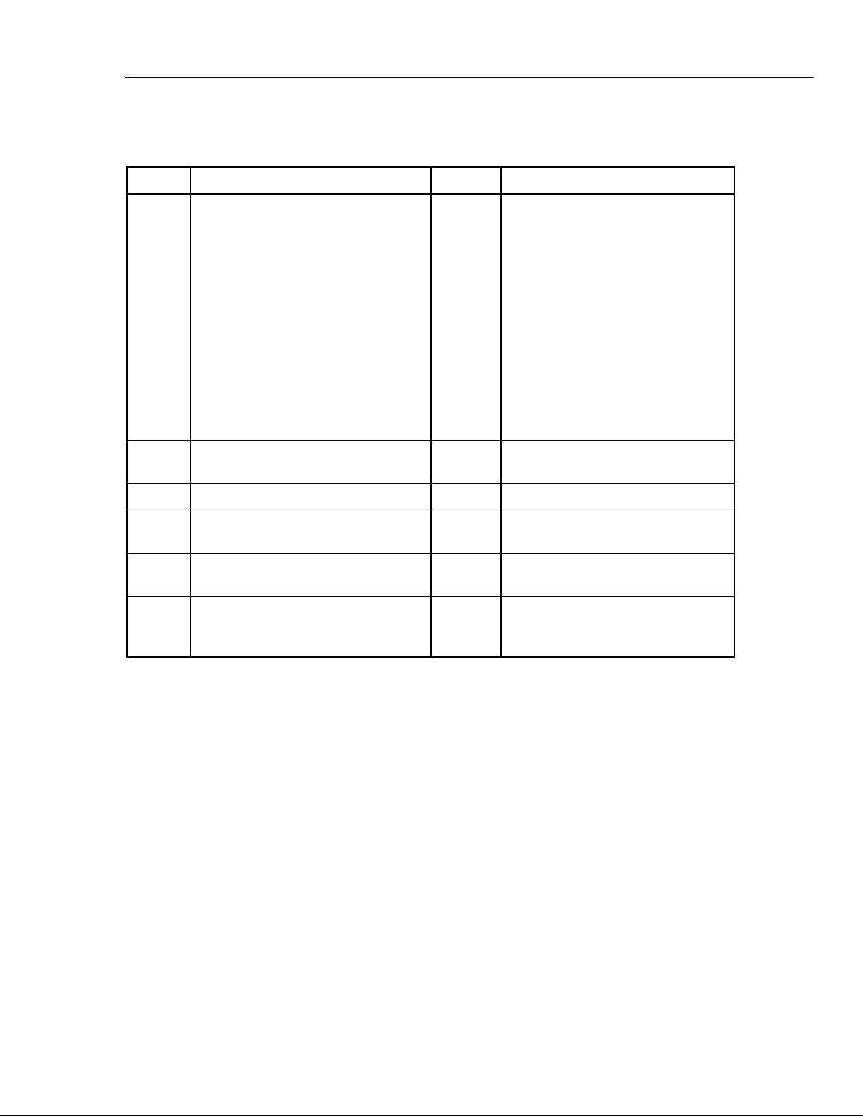
Table 1 shows the symbols used on the Product and in this manual.
Table 1. Symbols
Symbol Definition Symbol Definition
This product complies with the WEEE
Directive (2002/96/EC) marking
requirements. The affixed label
indicates that you must not discard this
electrical/electronic product in domestic
household waste. Product Category:
Risk of Danger. Important information.
See Manual.
With reference to the equipment types
in the WEEE Directive Annex I, this
product is classed as category 9
"Monitoring and Control
Instrumentation” product. Do not
dispose of this product as unsorted
municipal waste. Go to Fluke’s website
for recycling information.
Hazardous voltage. Risk of electric
shock.
Fuse
AC (Alternating Current) Protective Earth Ground
Earth Terminal
AC (Alternating Current) and DC (Direct
Current)
This product has been tested to the
requirements of CAN/CSA-C22.2
No. 61010-1, third edition.
DC (Direct Current)
Pressure
Conforms to European Union
directives.
3
Page 12

7526A
Calibration Manual
Specifications
General Specifications
Warm-up Time ....................................... Twice the time since last warmed up, to a maximum of 30 minutes
Settling Time ......................................... Less than 5 seconds for all functions and ranges except as noted
Standard Interfaces .............................. RS-232
Temperature Performance
Temperature Coefficient ....................... Temperature coefficient for temperatures outside tcal 5 °C is 10 % of the 90-day
Relative Humidity
Altitude
Operating .......................................... 3,000 m (9,800 ft) maximum
Non-operating ................................... 12,200 m (40,000 ft) maximum
Safety .................................................... EN/IEC 61010-1, ANSI/ISA 61010-1, CAN/CSA 22.2 No. 61010-1
EMC ........................................................ Complies with EN/IEC 61326-1, EN/IEC 61326-2-1 for controlled EM
Analog Low Isolation ............................ 20 V
Line Power Line Voltage (selectable)
120 V~ ................................................... 100 V to 120 V
240 V~ .................................................... 220 V to 240 V
Line Frequency ..................................... 47 to 63 Hz
Line Voltage Variation .......................... ±10 % about setting
Power Consumption ............................ 15 VA maximum
Dimensions
Weight (without options) ...................... 4.24 kg (9.35 lb)
IEEE-488 (GPIB)
Operating ........................................ 0 °C to 50 °C
Calibration (tcal) ............................. 18 °C to 28 °C
Storage ........................................... -20 °C to 70 °C
specification (or 1 year if applicable) per °C
Operating ........................................ <80 % to 30 °C
<70 % to 40 °C
<40 % to 50 °C
environments except when used in the following conditions:
• In electromagnetic fields from 0.08-2.7 GHz in excess of 1V/m.
• When subjected to electrostatic discharge (ESD) to the binding posts. Good
static awareness practices should be followed when handling this product
such as discharging any built up static charge to the product chassis prior to
handling terminals or test connections.
• When the product is used with data I/O cables in excess of 3 m.
Height ............................................. 14.6 cm (5.75 inch)
Width ............................................... 44.5 cm (17.5 inch)
Depth .............................................. 29.8 cm (11.75 inch) overall
4
Page 13
Precision Process Calibrator
Specifications
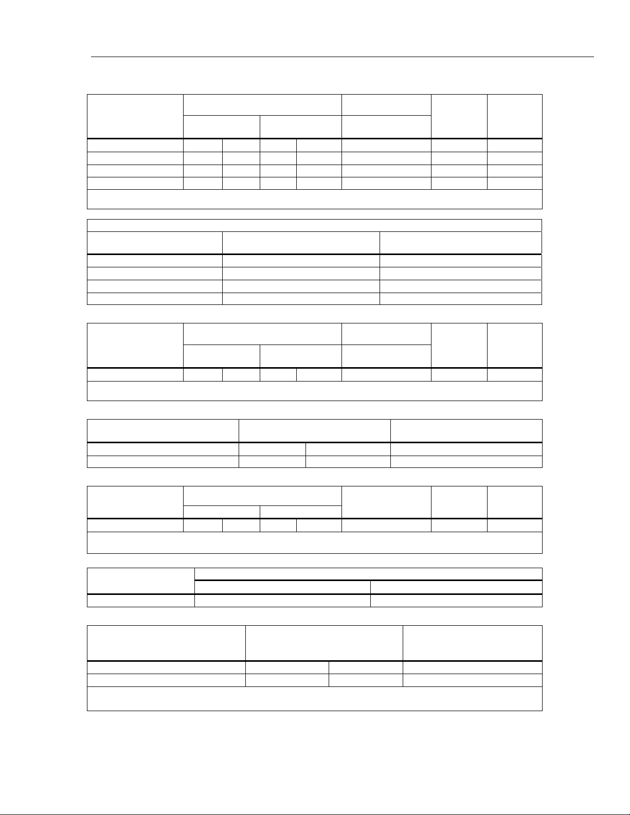
DC Voltage Specifications, Output
Absolute Uncertainty, tcal ±5°C,
Ranges
[1]
±(ppm of output +µV)
90 Days 1 Year
0 mV to 100.000 mV 25 3 30 3
0 V to 1.00000 V 25 10 30 10
0 V to 10.0000 V 25 100 30 100
0 V to 100.000 V 25 1 mV 30 1 mV 5 ppm + 1 mV 1 mV 1 mA
[1] All outputs are positive only, unless otherwise noted.
[2] Remote sensing is not provided. Output resistance is < 1Ω.
Noise
Ranges
0 mV to 100.000 mV
0 V to 1.00000 V
0 V to 10.0000 V
Bandwidth 0.1 to 10 Hz p-p
±(ppm of output +µV)
1 μV 6 μV
10 μV 60 μV
100 μV 600 μV
0 V to 100.000 V 10 ppm+1 mV 20 mV
Stability
24 hours, ±1 °C
Resolution
±(ppm of output +μV)
5 ppm + 2 μV 1 μV
4 ppm + 10 μV 10 μV
4 ppm + 100 μV 100 μV
Bandwidth 10 Hz to
10 kHz rms µV
Maximum
Burden
[2]
10 mA
10 mA
10 mA
DC Voltage Specifications, Thermocouple Jack, Input and Output
Absolute Uncertainty, tcal ±5°C,
Ranges
[1]
±(ppm of output +µV)
90 Days 1 Year
-10 to 75.000 mV 25
[1] All outputs are positive only, unless otherwise noted.
[2] Remote sensing is not provided. Output resistance is < 1Ω.
2 μV
30
2 μV 5 ppm + 2 μV 1 μV 10 Ω
Stability
24 hours, ±1 °C
±(ppm of output +μV)
Resolution
Maximum
Burden
[2]
DC Voltage Specifications, Isolated Input
Ranges
0 V to 10.0000 V 50 0.2
0 V to 100.000 V 50 2.0 1 mV
Absolute Uncertainty, tcal ±5 °C,
±(ppm of reading + mV)
Resolution
100 μV
DC Current Specifications, Output
Absolute Uncertainty, tcal ±5 °C,
± (ppm of output + µA)
Ranges
[1]
90 Days 1 Year
0 mA to 100.000 mA 40
[1] All outputs are positive only.
[2] For line voltages less than 95 V (±100 ppm of reading)
[2]
1 50
[2]
1
Ranges
Bandwidth 0.1 to 10 Hz p-p
0 mA to 100.000 mA 2000 nA
Resolution
1 μA
Noise
Bandwidth 10 Hz to 10 kHz rms μV
Maximum
Compliance
Voltage
12 V 100 mH
20 μA
DC Current Specifications, Isolated Input
Ranges
0 mA to 50.0000 mA 100 1
0 mA to 24.0000 mA (Loop Power)
[1] Loop Power: 24 V ±10 %
[2] HART Resistor: 250 Ω ±3 %
[1][2]
Absolute Uncertainty, tcal ±5 °C,
±(ppm of reading + μA)
100 1
Resolution
0.1 μA
0.1 μA
Maximum
Inductive
Load
5
Page 14
7526A
Calibration Manual
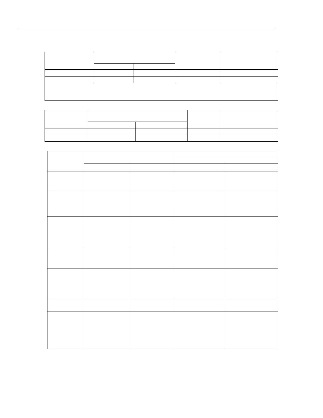
Resistance Specifications, Output
5 Ω to 400.000 Ω
5 Ω to 4.00000 kΩ
[1] For currents lower than shown, the specification becomes
For example, a 500 μA stimulus that measures 100 Ω has a specification of: 0.015 Ω x 1 mA/500 μA=0.03 Ω
Resistance Specifications, Input
0 Ω to 400.000 Ω ±20 ppm + 0.0035 Ω ±20 ppm + 0.004 Ω 0.001 Ω
0 Ω to 4.00000 kΩ ±20 ppm + 0.035 Ω ±20 ppm + 0.04 Ω 0.01 Ω
Absolute Uncertainty,
Ranges
New Spec. = Stated Spec. x Imin/Iactual.
Ranges
tcal ±5 °C, ± Ohms
90 Days 1 Year
0.012 0.015
0.25 0.3
Absolute Uncertainty, tcal ±5 °C
90 Days 1 Year
±(ppm of reading + Ω)
Resolution Nominal Current
0.001 Ω
0.01 Ω 100 μA to 1 mA
Resolution Stimulus Current
1 to 3 mA
1 mA
0.1 mA
[1]
Thermocouple Specification, Output and Input
Range (°C)
800 °C
1550 °C
1820 °C
1000 °C
1800 °C
2000 °C
2316 °C
-200 °C
-100 °C
0 °C
600 °C
1000 °C
-100 °C
800 °C
1200 °C
-200 °C
-100 °C
500 °C
800 °C
1372 °C
-100 °C
900 °C
-200 °C
-100 °C
0 °C
100 °C
800 °C
1300 °C
TC Type
B
C
E
J
K
L
N
Minimum Maximum 90 days 1 Year
600 °C
800 °C
1550 °C
0 °C
1000 °C
1800 °C
2000 °C
-250 °C
-200 °C
-100 °C
0 °C
600 °C
-210 °C
-100 °C
800 °C
-250 °C
-200 °C
-100 °C
500 °C
800 °C
-200 °C
-100 °C
-250 °C
-200 °C
-100 °C
0 °C
100 °C
800 °C
Absolute Uncertainty, tcal ±5 °C, ±(°C)
Output/Input
0.35 °C
0.28 °C
0.21 °C
0.15 °C
0.22 °C
0.24 °C
0.32 °C
0.24 °C
0.10 °C
0.07 °C
0.06 °C
0.08 °C
0.13 °C
0.07 °C
0.08 °C
0.45 °C
0.15 °C
0.08 °C
0.09 °C
0.11 °C
0.08 °C
0.07 °C
0.72 °C
0.22 °C
0.11 °C
0.09 °C
0.08 °C
0.10 °C
0.35 °C
0.28 °C
0.22 °C
0.16 °C
0.23 °C
0.26 °C
0.35 °C
0.25 °C
0.12 °C
0.09 °C
0.08 °C
0.10 °C
0.14 °C
0.09 °C
0.10 °C
0.46 °C
0.16 °C
0.10 °C
0.10 °C
0.13 °C
0.10 °C
0.09 °C
0.73 °C
0.23 °C
0.12 °C
0.11 °C
0.10 °C
0.12 °C
[1]
6
Page 15

Precision Process Calibrator
Specifications
TC Type
R
S
T
U
XK
Range (°C)
Minimum Maximum 90 days 1 Year
-50 °C
-25 °C
0 °C
100 °C
400 °C
600 °C
1000 °C
1600 °C
-50 °C
-25 °C
0 °C
100 °C
400 °C
600 °C
1000 °C
1600 °C
-250 °C
-200 °C
-100 °C
0 °C
200 °C
-200 °C
0 °C
200 °C
-200 °C
-100 °C
0 °C
600 °C
-25 °C
0 °C
100 °C
400 °C
600 °C
1000 °C
1600 °C
1767 °C
-25 °C
0 °C
100 °C
400 °C
600 °C
1000 °C
1600 °C
1767 °C
-200 °C
-100 °C
0 °C
200 °C
400 °C
0 °C
200 °C
600 °C
-100 °C
0 °C
600 °C
800 °C
Absolute Uncertainty, tcal ±5 °C, ±(°C)
Output/Input
0.54 °C
0.44 °C
0.38 °C
0.27 °C
0.21 °C
0.19 °C
0.18 °C
0.21 °C
0.51 °C
0.43 °C
0.37 °C
0.28 °C
0.22 °C
0.21 °C
0.20 °C
0.24 °C
0.34 °C
0.14 °C
0.09 °C
0.07 °C
0.06 °C
0.15 °C
0.08 °C
0.07 °C
0.10 °C
0.07 °C
0.06 °C
0.07 °C
0.55 °C
0.45 °C
0.39 °C
0.28 °C
0.22 °C
0.21 °C
0.19 °C
0.23 °C
0.51 °C
0.43 °C
0.38 °C
0.29 °C
0.23 °C
0.22 °C
0.22 °C
0.26 °C
0.35 °C
0.16 °C
0.11 °C
0.09 °C
0.09 °C
0.16 °C
0.10 °C
0.10 °C
0.11 °C
0.09 °C
0.08 °C
0.09 °C
[1]
0 °C
200 °C
BP
[1] Does not include thermocouple wire error.
Type B, E, J ,K, N, R, S and T are based on ITS-90
Type L and U are based on DIN 43710-1985
Type C is based on ASTM standard E 988-96
Type XK and BP are based on GOST R 8.585-2001
600 °C
800 °C
1600 °C
2000 °C
200 °C
600 °C
800 °C
1600 °C
2000 °C
2500 °C
0.17 °C
0.14 °C
0.15 °C
0.22 °C
0.26 °C
0.38 °C
0.18°C
0.16 °C
0.17 °C
0.23 °C
0.28 °C
0.40 °C
7
Page 16

7526A
Calibration Manual
RTD and Thermistor Specification, Output
RTD Types
Pt 385, 100 Ω -200 °C 800 °C 0.04 °C 0.05 °C
Pt 3926, 100 Ω -200 °C 630 °C 0.04 °C 0.05 °C
Pt 3916, 100 Ω -200 °C 630 °C 0.04 °C 0.05 °C
Pt 385, 200 Ω
Pt 385, 500 Ω -200 °C 630 °C 0.15 °C 0.17 °C
Pt 385, 1000 Ω -200 °C 630 °C 0.07 °C 0.09 °C
Ni 120, 120 Ω -80 °C 260 °C 0.02 °C 0.02 °C
Cu 427, 10 Ω
YSI 400
[1] 2-wire output
[2] Based on MINCO Application Aid No. 18
RTD and Thermistor Specification, Input
Pt 385, 100 Ω
Pt 3926, 100 Ω
RTD Type
Range °C
Minimum Maximum 90 Days 1 Year
-200 °C
400 °C
[2]
-100 °C 260 °C 0.30 °C 0.38 °C
15 °C 50 °C 0.005 °C 0.007 °C
Range (°C)
Minimum Maximum 90 Days 1 Year
-200 °C
-80 °C
100 °C
300 °C
400 °C
630 °C
-200 °C
-80 °C
0 °C
100 °C
300 °C
400 °C
400 °C
630 °C
-80 °C
100 °C
300 °C
400 °C
630 °C
800 °C
-80 °C
0 °C
100 °C
300 °C
400 °C
630 °C
Absolute Uncertainty, tcal ±5 °C ±(°C)
0.35 °C
0.42 °C
Absolute Uncertainty, tcal ±5 °C, ±(°C)
Output/Input
0.012 °C
0.018 °C
0.022 °C
0.025 °C
0.031 °C
0.037 °C
0.012 °C
0.014 °C
0.016 °C
0.022 °C
0.022 °C
0.024 °C
0.40 °C
0.50 °C
0.013 °C
0.020 °C
0.024 °C
0.026 °C
0.033 °C
0.038 °C
0.013 °C
0.015 °C
0.017 °C
0.022 °C
0.026 °C
0.032 °C
[1]
[1]
8
Pt 3916, 100 Ω
Pt 385, 200 Ω
Pt 385, 500 Ω
-200 °C
-190 °C
-80 °C
0 °C
100 °C
300 °C
400 °C
600 °C
-200 °C
-80 °C
0 °C
100 °C
260 °C
300 °C
400 °C
-200 °C
0 °C
100 °C
300 °C
400 °C
-190 °C
-80 °C
0 °C
100 °C
300 °C
400 °C
600 °C
630 °C
-80 °C
0 °C
100 °C
260 °C
300 °C
400 °C
630 °C
0 °C
100 °C
300 °C
400 °C
630 °C
0.009 °C
0.012 °C
0.014 °C
0.016 °C
0.021 °C
0.024 °C
0.030 °C
0.031 °C
0.047 °C
0.050 °C
0.053 °C
0.054 °C
0.062 °C
0.064 °C
0.079 °C
0.023 °C
0.026 °C
0.031 °C
0.035 °C
0.041 °C
0.010 °C
0.013 °C
0.015 °C
0.017 °C
0.022 °C
0.026 °C
0.031 °C
0.033 °C
0.053 °C
0.056 °C
0.060 °C
0.060 °C
0.069 °C
0.071 °C
0.088 °C
0.025 °C
0.028 °C
0.034 °C
0.038 °C
0.045 °C
Page 17

Precision Process Calibrator
Specifications
RTD Type
Minimum Maximum 90 Days 1 Year
-200 °C
0 °C
Pt 385, 1000 Ω
Ni 120, 120 Ω
Cu 427, 10 Ω
YSI 400
SPRT
[1] 4-wire mode. Uncertainties shown do not include probe uncertainties.
[2] Based on MINCO Application Aid No. 18.
100 °C
300 °C
400 °C
-80 °C 260 °C 0.008 °C 0.009 °C
[2]
-100 °C 260 °C 0.097 °C 0.110 °C
15 °C 50 °C 0.005 °C 0.007 °C
-200 °C 660 °C 0.05 °C 0.06 °C
Range (°C)
0 °C
100 °C
300 °C
400 °C
630 °C
Absolute Uncertainty, tcal ±5 °C, ±(°C)
Output/Input
0.014 °C
0.017 °C
0.022 °C
0.024 °C
0.031 °C
0.015 °C
0.018 °C
0.024 °C
0.026 °C
0.033 °C
[1]
Pressure Measurement Specifications
The Calibrator can accept the Fluke 700 or 525A-P Series pressure modules. Pressure modules connect directly into the
front panel Lemo connector with the Calibrator firmware auto-detecting the type and value of the module you connect.
Range Accuracy and Resolution Units
Determined by the pressure module Determined by the pressure module PSI (pounds per square inch)
in H2O 4 °C (inches of water at 4
degrees Celsius)
in H2O 20 °C (inches of water at 20
degrees Celsius)
in H2O 60 °C (inches of water at 60
degrees Fahrenheit)
cm H2O 4 °C (centimeters of water
at 4 degrees Celsius)
cm H2O 20 °C (centimeters of
water at 20 degrees Celsius)
mm H2O 4 °C (millimeters of water
at 4 degrees Celsius)
mm H2O 20 °C (millimeters of
water at 20 degrees Celsius)
BAR (bars)
mBAR (millibars)
kPa (kilopascals)
MPa (megapascals)
in HG 0 °C (inches of mercury at 0
degrees Celsius)
mm HG 0 °C (millimeters of
mercury at 0 degrees Celsius)
kg/cm2 (kilograms per square
centimeter)
Switch Test Specifications, Isolated Input
Contact Closure Resistance
Excitation Current 27 mA Max
<1 kΩ
9
Page 18

7526A
Calibration Manual
Maintenance
Clean the Product
Replace a Line Fuse
This section explains typical maintenance and tasks necessary to keep the Product in
service.
Warnings
To prevent possible electrical shock, fire, or personal injury:
• Have an approved technician repair the Product.
• Disconnect the mains power cord before you remove the
Product covers.
• Do not operate the Product with covers removed or the case
open. Hazardous voltage exposure is possible.
• Use only specified replacement parts.
Clean the Product and pressure modules with a soft cloth dampened with water, or mild
soap and water.
The line power fuses and line voltage selector are found in the compartment above the
power switch on the right rear side of the Product. Table shows the correct replacement
fuse for each line voltage setting.
Table 2. Replacement Fuses
Fuse Description Line Voltage Setting
0.25 A/250 V (SB) 120 V (Operating Range 90 V to 132 V)
0.125 A/250 V (SB) 240 V (Operating Range 198 V to 264 V)
To ensure safety, use exact replacement only.
To examine or replace a fuse:
1. Disconnect the mains power.
2. Use a flat-head screwdriver to pry up the tab at the base of the line fuse compartment.
Insert the blade into the center slot under the tab. The compartment cover will come
part way out. See Figure 1.
3. Remove the compartment cover. The fuses come out with the compartment cover and
can be examined or replaced.
4. To install the fuse holder, push the compartment cover back into the compartment
until the tab locks in position.
10
Page 19

Precision Process Calibrator
I
o
Maintenance
Change the Line Voltage
The Product comes from the factory configured for the line voltage applicable for the
country of purchase, or as specified when it is ordered. To verify the line voltage setting,
examine the line voltage indicator on the power line fuse compartment cover.
Make sure that the line voltage selection is set for 120 V for line voltages between 100 V
and 120 V ±10 % about setting. The selector must be set to 240 V for line voltages
between 220 V and 240 V ±10 % about setting.
Changing Line Fuse
Figure 1. Replace the Line Fuse
gxm009.eps
11
Page 20

7526A
Calibration Manual
Performance Tests
Required Test Equipment
Warning
To prevent possible electrical shock, fire, or personal injury, do
not perform the performance test procedures unless the
Product is fully assembled.
The performance tests verify the complete operation of the Product and measure the
accuracy of each function against Product specifications. If the Product fails a part of the
test, calibration adjustment or repair is necessary. See “Calibration Adjustment”.
The equipment listed in Table 3 is necessary to do the performance tests and calibration
adjustment.
Table 3. Required Equipment
Equipment Recommended Model Where Used
8-1/2 digit Precision Digital
Multimeter (DMM)
Ohms shorting block
1 Ω Resistance Standard Fluke 742A-1 DC current
Resistance standard, 10 Ω Fluke 742A-10 100 mA source calibration
Resistance standard, 100 Ω Fluke 742A-100
1 KΩ Resistance Standard Fluke 742A-1K Resistance
10 KΩ Resistance Standard Fluke 742A-10K Resistance
Multifunction Calibrator Fluke 5522A DC volts, dc current, resistance
Thermistor probe Fluke5640-D TC CJC calibration
Thermocouple probe
Pressure Module Any Fluke 700 Series Module Pressure
Lead Set 5520A-525A/LEADS Leads Kit Necessary test cables
Precision Thermistor Fluke 5640-D Temperature
Fluke 8508A DC volts, dc current, resistance
Low ohms measure and SPRT
calibration and high ohms
measure calibration
Low ohms measure and SPRT
calibration
Omega E-type thermocouple
probe
TC CJC calibration
12
Thermometer Readout Fluke 1504 Temperature
Dewar Flask with Lid - - - Thermocouple
Characterized Type E
Thermocouple
Banana Jack to Copper TC Miniconnector
Lag bath TC CJC calibration
- - - Thermocouple
- - - Thermocouple
Page 21

Precision Process Calibrator
Performance Tests
DC Voltage
The dc voltage performance test verifies the accuracy of the Volts Source output from
the front panel of the Product. Verify the measurements shown in Table 4 with a digital
multimeter (DMM).
Table 4. DC Voltage Verification
Range Nominal Value Measured Value
0 V 3.00E-06 3.00E-06
0.035 V 3.88E-06 4.05E-06
100 mV
0.065 V 4.63E-06 4.95E-06
0.1 V 5.50E-06 6.00E-06
0 V 1.00E-05 1.00E-05
0.35 V 1.88E-05 2.05E-05
1.0 V
0.65 V 2.63E-05 2.95E-05
1 V 3.50E-05 4.00E-05
0 V 1.00E-04 1.00E-04
3.5 V 1.88E-04 2.05E-04
10.0 V
6.5 V 2.63E-04 2.95E-04
10 V 3.50E-04 4.00E-04
0 V 1.00E-03 1.00E-03
35 V 1.88E-03 2.05E-03
100.0 V
65 V 2.63E-03 2.95E-03
90-Day
Specification
(V)
1-Year
Specification
(V)
100 V 3.50E-03 4.00E-03
13
Page 22

7526A
O
Calibration Manual
DC Current
The dc current performance test verifies the accuracy of the current output from the front
panel of the Product. Use the 8508A and the precision shunt to measure the Product
output. Divide the voltage indication from the 8508A by the 742A-1 actual value to
determine the current output. Verify the measurements shown in Table 5. See Figure 2
for connections.
Table 5. DC Current Verification
100 mA
Output
Volt
Current
(I=E/R)
742A-1 Shunt
Value
90-Day
Specification
1-Year
Specification
Direct into
8508A
0.000 mA
Current Input,
1.0 μA 1.0 μA
Autorange
35.000 mA 2.4 μA 2.75 μA
65.000 mA 3.6 μA 4.25 μA
100.000 mA 5 μA 6 μA
7526A
8508A
PRECISION PROCESS CALIBRAT
7526A
Current Shunt
OUTPUT
100V MAX
20V PK
MAX
CURRENT
20V PK
MAX
VOLTS
4
W RTD/
INPUT
100mA MAX
HI
LO
HI
LO
RTD/
mA
OUTPUT
HI
LO
SENSE
14
gxm010.eps
Figure 2. DC Current Performance Test Connections
Page 23

Precision Process Calibrator
Performance Tests
Thermocouple Output
The thermocouple (TC) output performance test verifies the accuracy of the TC output on
the front panel of the Product. Thermocouple mV specifications will be used for this test.
When this test is combined with the cold junction compensation (CJC) test, all functions
of the TC output are checked. The cable necessary to connect the Product to the 8508A
will need to be constructed. The TC mini-connector needs copper-copper (white). With
copper wire, connect the mini-connector to standard banana jacks. See Figure 3 for
connections.
1. Push and then to select TC output.
2. Push until mV/°C shows on the display.
3. Output the mV values listed in Table 6.
Table 6. TC mV Test
Nominal Voltage 90-Day Specification 1-Year Specification
-10.000 mV 3.125 μV 3.15 μV
15.000 mV 3.375 μV 3.45 μV
35.000 mv 3.750 μV 3.90 μV
55.000 mV 4.250 μV 4.50 μV
75.000 mV 4.750 μV 5.10 μV
8508A
7526A
VOLTS
OUTPUT
100V MAX
20V PK
MAX
4
CURRENT
20V PK
MAX
7526A
PRECISION PROCESS CALIBRATOR
mA
100mA MAX
HI
HI
LO
W RTD/
INPUT
HI
LO
HI
LO
SENSE
RTD/
OUTPUT
TC
INPUT/OUTPUT
20V PK
MAX
Figure 3. Thermocouple Output Performance Test Connections
gxm011.eps
15
Page 24

7526A
Calibration Manual
CJC (Cold Junction Compensation)
The CJC performance test verifies the accuracy of the cold junction compensation of the
Product. Connect a Type-E thermocouple to the TC terminals on the Product. Immerse
the thermocouple and a precision thermometer in a mineral oil lag bath. See Figure 4 for
connections.
1. Push then to switch to TC input.
2. Push then to turn on the internal junction. XCJC is not shown when the
internal junction is used.
3. Push until Type E is shown on the display.
Make sure that the indications of the Product and the precision thermometer are within
the Type-E specifications:
• 90-Day specification is 0.06 °C
• 1-Year specification is 0.08 °C
7526A
OUTPUT
100V MAX
20V PK
MAX
CURRENT
20V PK
MAX
PRECISION PROCESS CALIBRATOR
7526A
VOLTS
100mA MAX
HI
LO
4
W RTD/
INPUT
HI
LO
RTD/
mA
OUTPUT
HI
HI
LO
SENSE
TC
INPUT/OUTPUT
20V PK
MAX
Figure 4. CJC Performance Test Connections
Precision
Thermometer
Dewar Flask
and Cap
Mineral Oil
Lag Bath
gxm012.eps
16
Note
Typical Type-E thermocouples do not have specifications accurate enough
to be used as a standard. To maintain a good test uncertainty ratio (TUR),
a characterized Type-J thermocouple can be used.
Page 25

Precision Process Calibrator
CURRENT
OUTPUT
HI
VOLTS
mA
RTD/
OUTPUT
HI
LO
HI
LO
LO
TC
SENSE
INPUT/OUTPUT
4
W RTD/
INPUT
20V PK
MAX
100 V MA X
100 mA MAX
20V PK
MAX
20V PK
MAX
PRECISION PROCESS CALIBRATOR
7526A
Performance Tests
Thermocouple Input
The TC input performance test verifies the accuracy of the TC input. Push and then
on the Product to set the Product to TC input. All Product conditions will be the
same as the Thermocouple Output test mode (CJC off, mV/ °C). Set the 5522A to the mV
values listed in Table 6. See Figure 5 for connections.
Calibrator
5522A
CALIBRATOR
Figure 5. TC Input Performance Test Connections
7526A
HI
gxm013.eps
17
Page 26

7526A
Calibration Manual
Ohms Output
The ohms output performance test verifies the accuracy of the ohms output from the front
of the Product. Use the DMM to measure the ohms output. Apply the values shown in
Table 7. See Figure 6 for connections.
Note
Make sure the sense wires from the 8508A are on the bottom of the
stackable leads.
Push to select the 400 Ω, then the 4000 Ω range.
Note
The 8508A should be set to the 2 k
400
Ω
range. After the 1000 Ω measurement, the 8508A should be set to the
20 k
Ω
range with loI off. To prevent an overload, the 8508A must be in the
“loI” (low current mode) to measure 5
Ω
range when you measure the 7526A
Ω
in the 4 kΩ range.
7526A
400 Ω
8508A
OUTPUT
100 V MA X
20V PK
MAX
CURRENT
20V PK
MAX
PRECISION PROCESS CALIBRATOR
7526A
VOLTS
HI
LO
4
W RTD/
INPUT
HI
LO
mA
100 mA MAX
HI
HI
LO
SENSE
RTD/
OUTPUT
TC
INPUT/OUTPUT
20V PK
MAX
gxm014.eps
Figure 6. Resistance Output Performance Test Connections
Table 7. Ohms Output Ranges
Range Output 90-Day Specification 1-Year Specification
5 Ω 0.012 Ω 0.015 Ω
100 Ω 0.012 Ω 0.015 Ω
200 Ω 0.012 Ω 0.015 Ω
18
4000 Ω
300 Ω 0.012 Ω 0.015 Ω
400 Ω 0.012 Ω 0.015 Ω
5 Ω 0.25 Ω 0.30 Ω
1000 Ω 0.25 Ω 0.30 Ω
2000 Ω 0.25 Ω 0.30 Ω
3000 Ω 0.25 Ω 0.30 Ω
4000 Ω 0.25 Ω 0.30 Ω
Page 27

Precision Process Calibrator
Performance Tests
Ohms Input
The ohms input performance test verifies the ohms input on the front of the Product.
Before an ohms input is measured, the ohms output of a 5522A must be “characterized”.
To get the necessary accuracy, the 8508A is used as a transfer standard and the 742A is
used as the reference standard. To find the true value of the 5522A output, use the ratio
input function of the 8508A. This is located on the front and rear panels. Connect the
742A to the front terminal and connect the 5522A to the rear terminals. Use four-wire
measure for both. See Figure 7 for connections.
8508A Front 8508A Rear
SENSE (4 WIRE )
INPUT (2 WIRE)
TRIG
5V PK MAX
ENABLE
DISABLE
CALIBRATION
REAR INPUT
CURRENT
FUSE.
F 1.6AH
5x20mm
IEC127
HI
LO
A
1420V
PK MAX
3A PK MAX
CAT I @ 1000V
PK MAX
HI
LO
GU
920V
Hi
Hi
Lo
Sense Hi
Sense Lo
742A
Lo
Sense Hi
Sense Lo
5520A
gxm015.eps
Figure 7. Ohms Input Performance Test Connections
19
Page 28

7526A
Calibration Manual
Use the 742A-1K for the 400 Ω range. Use the 742A-10K for the 4 KΩ range. For more
information about how to use the ratio mode, see the 8508A Operators Manual. Note the
ratio indication on the 8508A in Table 8. Use the formula: (742A actual value/ratio
indication x 100 = actual 5522A actual value). Start with the 7526A in the 400 Ω range.
After the 400 Ω test, change the 7526A to the 4000 Ω range.
Table 8. Ohms Ratio Table
742A
Range
0 Ω 0.0035 Ω 0.004 Ω
25 Ω 0.004 Ω 0.0045 Ω
75 Ω 0.005 Ω 0.0055 Ω
95 Ω 0.0054 Ω 0.0059 Ω
100 Ω 0.0055 Ω 0.0060 Ω
105 Ω 0.0056 Ω 0.0061 Ω
150 Ω 0.0065 Ω 0.007 Ω
300 Ω 0.0095 Ω 0.010 Ω
400 Ω 0.0115 Ω 0.012 Ω
0 Ω 0.035 Ω 0.04 Ω
250 Ω 0.04 Ω 0.045 Ω
750 Ω 0.05 Ω 0.055 Ω
1000 Ω 0.055 Ω 0.06 Ω
1500 Ω 0.065 Ω 0.07 Ω
Value
(Ω)
Ratio
5522A
Actual
Value (Ω)
7526A
Reading
90-Day
Specification
1-Year
Specification
20
2000 Ω 0.075 Ω 0.08 Ω
3000 Ω 0.095 Ω 0.10 Ω
4000 Ω 0.115 Ω 0.12 Ω
Page 29

Precision Process Calibrator
O
Performance Tests
To test the ohm input:
1. Apply a four-wire short to the Product 4W RTD/Ω input.
2. For the first test, set the Product to the 400 Ω range.
3. For the second test, connect the Product 4W RTD/Ω input to the output of the 5522A
as shown in Figure 8.
4. Set the Product to the 400 Ω range. Note the indication in Table 8.
5. Set the Product to the 4000 Ω range after the 400 Ω test. Note the indication in
Table 8.
6. Output the same nominal values and note the Product indication in the 7526A
Reading column of Table 8.
7. Subtract the 5522A Actual Value from the 7526A Reading and ensure that it is
within the specified tolerance.
Calibrator
CALIBRATOR
5522A
Figure 8. Ohms Measurement Performance Test Connections
OUTPUT
100 V MA X
20V PK
MAX
CURRENT
20V PK
MAX
VOLTS
7526A
7526A
HI
LO
4
W RTD/
INPUT
HI
LO
PRECISION PROCESS CALIBRAT
RTD/
mA
100 mA MAX
OUTPUT
HI
LO
SENSE
gxm016.eps
21
Page 30

7526A
Calibration Manual
Pressure Modules
The Fluke 700 and 525A-P series pressure modules are calibrated separately from the
Product. Only a performance test is necessary. Connect any of the Fluke 700 and 525A-P
series pressure modules to the pressure module connector. Make sure that the Product
reads pressure. See Figure 9 for connections.
7526A
Pressure Module
PRECISION PROCESS CALIBRATOR
OUTPUT
100V MAX
20V PK
MAX
CURRENT
20V PK
MAX
VOLTS
7526A
HI
4
HI
LO
W RTD/
INPUT
HI
LO
mA
100mA MAX
LO
SENSE
RTD/
OUTPUT
HI
INPUT/OUTPUT
MAX TORQUE, SEE MANUAL
700PD6
LH
PRESSURE MODULE
RANGE
-15/+100 PSIG
-1/+7 bar
BURST PRESSURE 300 PSIG
TC
20V PK
MAX
Figure 9. Pressure Module Performance Test Connections
gxm017.eps
22
Page 31

Precision Process Calibrator
20 V PK
MAX
HI
INPUT
LO
Press for
VOLTS/mA
Press and Hold
for Switch Test
Switch Test
Reset
LOOP
HART
PWR
VOLTS/mA
SW TEST
Performance Tests
Isolated DC Voltage
The isolated dc voltage performance test verifies the accuracy of the isolated dc voltage
source output from the front panel of the Product. Connect the 5522A Normal HI and LO
to the Product Isolated input HI and LO jacks located on the right side of the Product.
Verify the measurements listed in Table 9. See Figure 10 for connections.
Table 9. Isolated DC Voltage
Range Nominal Value Measured Value Deviation % Specification
0 V 0.0002 V
10.0 V
100.0 V
2.500 V 0.0003 V
5.000 V 0.0005 V
10.000 V 0.0007 V
0 V 0.002 V
25 V 0.003 V
50 V 0.005 V
75 V 0.006 V
100 V 0.007 V
7526ACalibrator
CALIBRATOR
5522A
gxm018.eps
Figure 10. Isolated DC Voltage Performance Test Connections
23
Page 32

7526A
20 V PK
MAX
HI
INPUT
LO
Press for
VOLTS/mA
Press and Hold
for Switch Test
Switch Test
Reset
LOOP
HART
PWR
VOLTS/mA
SW TEST
Calibration Manual
Isolated DC Current
0.000 mA 0.0010 mA
25.000 mA 0.0035 mA
50.000 mA 0.0060 mA
The isolated dc current performance test verifies the accuracy of the isolated dc current
source output from the front panel of the Product. Connect 5522A Normal HI to the
Product Isolated Input LO. Connect the Product Isolated input HI to 8508A input A.
Connect 8508A Input LO to 5522A Normal LO. Use the 8508A to measure the 5522A
output as shown in Figure 2. Take the dc current indication from the 8508A as the
applied current. Verify the measurements listed in Table 10. See Figure 11 for
connections.
Table 10. Isolated DC Current
50 mA Input 8508A Reading Specification
7526A
Calibrator
5522A
Figure 11. Isolated DC Current Performance Test Connections
Isolated Loop Power
1. Connect a 1 kΩ, 1%, 1 W resistor across Isolated Input HI and LO.
CALIBRATOR
8508A
gxm019.eps
24
2. Set Isolated input to mA.
3. Push L. The upper ISO display shows 24 mA LPWR. The indication on the ISO
lower display must be between 26.300 mA to 21.500 mA to pass.
4. Push . The indication must be between 21.336 mA to 17.104 mA to pass.
The verification procedure is complete. If any steps did not pass, adjustment or repair is
necessary.
Page 33

Precision Process Calibrator
Calibration Adjustment
Calibration Adjustment
The Product features electronic calibration adjustment. There are no mechanical
adjustments. Calibration adjustment is done with the case closed through the serial
communications port that sends and receives commands and readings with a RS232
interface.
The adjustment procedure for resistance measure is flexible to allow for the use of fixed
resistors. See Table 3 for the required equipment.
Initiate Communication
Terminal communications can be set up with terminal communication software on a
personal computer (PC). Connect a 9-pin null modem cable to the RS232 connector on
the back of the Product. Connect the other end of the cable to the PC/PC serial port. An
adapter may be necessary for terminals that use 25 pin “D” serial connectors. A terminal
program, such as Windows HyperTerminal, can be used in the PC. The terminal settings
must be set as follows:
• Bits per second: 9600
• Data bits: 8
• Parity: None
• Stop bits: 1
• Flow control: None
• Local echo: on
Starting Adjustment Mode
The Product temperature must be stable before calibration adjustments are done. Make
sure the Product has warmed up for a minimum of 30 minutes. To start the calibration
mode, use the PC terminal program to send the CAL_START command.
The PC shows:
Calibration is password protected
Enter Password:
Correctly enter the password with the PC keyboard. The password is 525.
25
Page 34

7526A
Calibration Manual
The PC shows the calibration adjustment steps:
Calibration Menu
1: 100 mV Source
2: 1 V Source
3: 10 V Source
4: 100 V Source
5: 100 mA Source
6: Hi Ohms Source
7: Low Ohms Source
8: Hi Ohms Measure
9: 1K Ohms Measure
10: Low Ohms Measure
11: 100 Ohms Measure
12: TC SOURCE
13: TC READ
14: TC CJC
15: mA Read
16: 10V Read
17: 100V Read
18: Exit
Enter Selection:
Adjustment Sequence
Calibration adjustment is a menu-driven process. Fluke Calibration recommends that
calibration be done in the order specified by the menu. However, each step is independent
and can be performed separately if necessary, with the exception of the TC function. The
TC calibration adjustment must be done in the order shown in the menu (steps 1-18). TC
read uses the internal source mode and it must be adjusted after TC source. Do not source
with an external instrument for TC read. Connect a DMM and adjust the output to the
necessary value with the PC keyboard.
Exit the calibration mode at any time by typing 18.
Steps 1 through 4: DC mV and DC V Source Adjustment
Voltage output adjustment is done for four distinct ranges. Each range can be adjusted
separately with menu selections 1 through 4. The adjustment of each range uses the same
procedure and is done in two parts. The first part sets the zero and span values. The
second part fine-adjusts the zero, span, and adjusts the linearity if necessary. See Table 3
for the test equipment used for this procedure.
Connect the Product volts HI and LO to the DMM input. Set the DMM to measure
dc volts. See Figure 12 for connections.
26
Page 35

Precision Process Calibrator
O
Calibration Adjustment
7526A
8508A
PRECISION PROCESS CALIBRATOR
7526A
RTD/
mA
OUTPUT
HI
LO
SENSE
gxm020.eps
OUTPUT
100V MAX
20V PK
MAX
CURRENT
20V PK
MAX
VOLTS
4
W RTD/
INPUT
100mA MAX
HI
LO
HI
LO
Figure 12. DC Volts Source Performance Test Connections
Enter 2 on the PC to choose the 1 V source calibration.
The value for the first calibration point (approximately 0 V) will be sourced by the
Product. When the output is stable, type the value shown on the DMM. After the value is
entered, the value for the second calibration point (approximately 1 V) will be sourced by
Product. Type the new value to complete the 1 V source calibration.
Step 5: 100 mA Source - DC Current Source Adjustment
The dc current output adjustment uses similar calibration steps to the voltage source
calibration. The adjustment is done in two parts. The first part sets the zero and span
values. The second part fine adjusts the zero, span and the linearity if necessary. Table 3
for the test equipment used for this procedure. See Figure 13 for connections.
742A
8508A
Figure 13. High and Low Ohms Adjustment Connections
OUTPUT
100 V MA X
20V PK
MAX
CURRENT
20V PK
MAX
VOLTS
7526A
4
W RTD/
INPUT
HI
LO
HI
LO
7526A
PRECISION PROCESS CALIBRAT
RTD/
mA
100 mA MAX
OUTPUT
HI
LO
SENSE
gxm023.eps
The voltage is measured across a 10 Ω shunt resistor instead of measuring current
directly. Readings from the DMM must be converted to mA (multiplied by 100) before
they can be entered with the PC. Set the DMM to read DC Volts.
27
Page 36

7526A
Calibration Manual
Steps 6 and 7: Hi Ohms Source and Low Ohms Source Adjustment
Enter 5 on the PC. The calibration procedure for current output is similar to voltage
output except there is only one range and the voltage is measured across a 10 Ω shunt
resistor instead of a direct current measurement. Readings from the DMM must be
converted to mA (multiplied by 100) before they can be entered on the PC.
When the 5 Ω - 4000 Ω output range (high ohms source) is calibrated, the Product
outputs two calibration points. After the output becomes stable, the values are entered at
the PC. See Table 3 for the test equipment used for this procedure. See Figure 14 for
connections.
7526A
8508A
PRECISION PROCESS CALIBRATOR
7526A
RTD/
mA
OUTPUT
HI
LO
SENSE
INPUT/OUTPUT
OUTPUT
100V MAX
20V PK
MAX
CURRENT
20V PK
MAX
VOLTS
4
W RTD/
INPUT
100mA MAX
HI
LO
HI
LO
Figure 14. Hi Ohms Source and Low Ohms Source Adjustment Connections
It is important that the sense leads be on the bottom of the stack on the Product ohms
source jacks.
1. Set the DMM to measure 4-wire ohms.
2. The calibration of the 5 Ω - 4000 Ω output range (high ohms source) is similar to the
voltage source calibration. The Product outputs two calibration points. After the
output becomes stable, enter the values on the PC.
TC
20V PK
MAX
gxm021.eps
28
It is recommended to lock the DMM in the proper range (first range greater than
4000 Ω). The maximum excitation current of the DMM is 1 mA.
3. Enter the ohms shown on the DMM at the PC. The Product sources the maximum
value.
4. Enter the ohms shown on the DMM at the PC. After the value has been entered for
the second calibration point you will return to the main calibration menu.
The calibration of the 5 Ω - 400 Ω output range (low ohms source) is similar. The
maximum excitation current of the DMM is 3 mA.
Page 37

Precision Process Calibrator
O
0
1
2
45
7
8
/
+
OPR
STBY
5522A
CALIBRATOR
Calibration Adjustment
Steps 8 through 11: 100 Ohms Measure, Resistance Measure Adjustment
The ohms measure calibration adjustment allows the use of a medium-quality resistor
decade in conjunction with a good-quality DMM by using flexible calibration points.
This way, if resistance standards are not available, the resistor decade can be set to 1 K,
the actual value of the DMM value can be read (1002.45 Ω for example), and this value
can be entered when asked for 1000 Ω.
You can use a resistor decade box, adjustable in 25 Ω to 4000 Ω range, to cover all of the
values that are requested (maximum 5 % tolerance):
• 25 Ω
• 50 Ω
• 100 Ω
• 200 Ω
• 400 Ω
• 1000 Ω
• 2000 Ω
• 4000 Ω
The subsequent procedure uses the Fluke 5522 for ohms source to adjust the Product
reading. See Table 3 for the test equipment used for this procedure. See Figure 15 for
connections.
Calibrator
OUTPUT
100 V MA X
20V PK
CURRENT
20V PK
7526A
PRECISION PROCESS CALIBRAT
7526A
VOLTS
MAX
MAX
4
W RTD/
INPUT
LO
LO
HI
HI
mA
100 mA MAX
Figure 15. 100 Ohms Measure, Resistance Measurement Adjustment Connections
HI
LO
SENSE
RTD/
OUTPUT
gxm024.eps
29
Page 38

7526A
Calibration Manual
Step 12: TC SOURCE, TC mV Source Adjustment
This adjustment procedure requests approximately:
• 1000 Ω
• 2000 Ω
• 4000 Ω
The actual value used must be entered.
1. For the 0 Ω connection, connect a short to the 4 terminals for 4W RTD/Ω.
2. For the 5522A connections, see Figure 15 for connections.
3. Follow the steps in the menu.
4. Use the 5522A to enter 4000 Ω (nominal) and enter the actual value calculated as
described above.
5. Repeat for all calibration points.
The adjustment of the TC Source output range is similar to the first part of the voltage
source calibration. Use the test leads and a DMM for this procedure.
Use a copper TC mini-plug cable with low thermal EMF jacks on the other end to
connect the Product to the DMM. Make sure the polarity is correct. Set the DMM to read
dc volts.
Enter 12 at the PC. The calibration of the TC source output range is similar to the first
part of the voltage source calibration. The Product outputs two calibration points, after
the output becomes stable, enter the values on the PC.
After the mV reading on the DMM is entered, you are prompted to enter the second
calibration point.
30
Page 39

Precision Process Calibrator
Calibration Adjustment
Step 13: TC Read, TC mV Measure Adjustment
The adjustment of the TC source output range is similar to the first part of the voltage
source calibration. The Product outputs two adjustment points. After the output becomes
stable, the values can be entered at the PC. Use the test leads and a DMM for this
procedure.
Use a copper TC mini-plug cable with low thermal EMF jacks on the other end to
connect the Product to the DMM. Make sure the polarity is correct. Set the DMM to read
dc volts.
Enter 13 on the PC. The calibration of the TC read input range is based on the TC source.
Make sure that TC source is calibrated first.
The Product sources 5 calibration points:
• -10 mV
• 15 mV
• 40 mV
• 65 mV
• 75 mV
For each test point, push 8 and 2 on the PC to adjust the output if necessary. Use the
8508A indication to monitor this voltage. After the output is within 1 μV of the necessary
value, push ENTER on the PC to go to the next calibration point.
Step 14: TC Cold Junction Temperature (TC CJC) Adjustment
The Calibration of the thermocouple cold junction temperature (TC CJC) is a critical part
of the adjustment process. It is important that the thermocouple junction be completely
stable. Use the precision thermometer, E thermocouple probe, lag bath, and thermistor
probe for this procedure. See Figure 4 for connections.
The precision thermometer probe must already be in the lag bath along with the E
thermocouple probe. Plug the mini-plug on the E thermocouple probe into the TC jack on
the Product.
Enter 14 at the PC
. It is important that the thermocouple junction be completely stable.
After the TC junction is stable, enter the temperature from the temperature reference.
Push ENTER on the PC to return to the calibration menu.
Step 15: mA Read Adjustment
Connect 5522A mA source jacks to Product isolated jacks and add the 742A-1 resistance
standard in series. Use the sense jacks of the resistor to monitor the voltage drop on the
resistor with the 8508A DMM. See Table 3 for the test equipment used for this
procedure.
Connect 5522A mA source jacks to the Product isolated jacks and add the 742A-1
resistance standard in series. Use the sense jacks of the resistor standard to monitor the
voltage drop on the resistor with the 8508A DMM. See Table 3 for the test equipment
used for this procedure. See Figure 16 for connections.
31
Page 40

7526A
20 V PK
MAX
HI
INPUT
LO
Press for
VOLTS/mA
Press and Hold
for Switch Test
Switch Test
Reset
LOOP
HART
PWR
VOLTS/mA
SW TEST
0
1
2
45
7
8
/
+
OPR
STBY
5522A
CALIBRATOR
Calibration Manual
7526A5522A
742A
Figure 16. mA Read Adjustment Connections
Enter 15 at the PC. Source five calibration points from the 5522A:
• 0 mA
• 13 mA
• 26 mA
• 39 mA
• 52mA
For each calibration point adjust the current for the maximum accuracy with the DMM
indication as feedback. Push ENTER on the PC when stable to go to the next calibration
point.
Step 16: 10 V Read Adjustment
Connect 5522A V source jacks to 7526A isolated jacks. Use the 8508A DMM to monitor
the voltage.
8508A
gxm026.eps
32
Enter 16 on the PC. Source three calibration points from the 5522A:
• 0 V
• 5 V
• 10 V
For each calibration point, adjust the voltage for the maximum accuracy. Use the DMM
indication as feedback. Push ENTER on the PC when stable to go to the next calibration
point. See Table 3 for the test equipment used for this procedure. See Figure 17 for the
connections.
Page 41

Precision Process Calibrator
100 V PK
MAX
HI
INPUT
LO
Press for
VOLTS/mA
Press and Hold
for Switch Test
Switch Test
Reset
LOOP
HART
PWR
VOLTS/mA
SW TEST
Calibration Adjustment
7526A
Calibrator
CALIBRATOR
5522A
8508A
Figure 17. 10 V Read Adjustment Connections
Step 17: 100 V Read Adjustment
Use the test equipment shown in Table 3. Connect the 5522A V source jacks to the
Product isolated jacks. Use the 8508A DMM to monitor the voltage. See Figure 17 for
the connections.
Enter 17 on the PC. Source three calibration points from 5522A:
• 0 V
• 50 V
• 100 V
For each calibration point, adjust the voltage for the maximum accuracy. Use the DMM
indication as feedback. Push ENTER on the PC when stable to go to the next calibration
point.
Calibration is complete. Enter 18 at the PC to exit calibration mode.
gxm022.eps
33
Page 42

7526A
Calibration Manual
User-Replaceable Parts
User-replaceable parts are listed in Table 11 and shown in Figure 18. To get parts and
accessories, see the “Contact Fluke Calibration” section.
Table 11. User-Replaceable Parts
Item
Number
Fluke Part Number Description Quantity
4285232 7526A Chassis, Base and Top 1
295105 Allen Head Screw 20
3693680 Chassis Cap 2
3468883 Chassis Handles with Grip 2
4285267 7526A Front Panel Decal 1
4285271 7526A Keypad 1
886382 Red 5-Way Binding Post 6
886379 Black 5-Way Binding Post 6
868786 Plastic Feet 4
152165 #6 X 3/8 in. Screw, PH 1
1601078 Programming Door 1
1645311 Fuse, (1/4A), Fuse for 120 VAC (nominal) 2
1645327 Fuse, (1/8A), Fuse for 240 VAC (nominal) 2
448092 Jack Screw RS232 Conn 1
102889 Binding Head Thumbscrew 1
Not Shown 320093 Flathead Screw 10
Not Shown 859939 #8 Washer, Low Thermal 28
Not Shown 850334 8-32 Nut, Low Thermal 24
Not Shown 1640305 Nylock Nut 6-32 5
Not Shown 1618621 Line Cord, 3 COND 1
Not Shown 4181286 7526A Manual CD-Rom 1
Not Shown 4218030 7526A Getting Started 1
To ensure safety, use exact replacement only.
34
Page 43

Precision Process Calibrator
User-Replaceable Parts
1
32x
2
20x
5
7526A
PRECISION PROCESS CALIBRATOR
VOLTS
mA
1
00
RT
mA MAX
D
/
O
U
T
P
UT
HI
HI
OUTPUT
1
0
0
V MAX
LO
2
0
V
P
K
LO
2x
4
MAX
CURRENT
2
0
V PK
MAX
TC
OUTPUT
INPU
4
W RT
D/
INP
UT
HI
SENSE
LO
INPUT
T/
OUTPUT
20
V PK
MAX
ZERO
DISPLAY
C / FCJC
SET
RECALL
AUTOSET
RNG LOCK
LOCAL
EXP
Press and Hold
for Switch Test
Switch Test
Reset
HI
INPU
T
1
0
0
V MAX
LO
20
V
P
K
MAX
6
94x
6x
7
6x
8
2x
15
10
11
14
12 13
gxm027.eps
Figure 18. User-Replaceable Parts
35
Page 44

7526A
Calibration Manual
Accessories
1622027 Fluke Y7526A Rack Mount Kit
946470 RS43, RS232 Null Modem Cable
7526A-CASE Carrying Case
1618621 120 V Line Cord (US Plug)
769422 240 V Line Cord (Schuko Plug)
658641 240 V Line Cord (Australian Plug)
769448 240 V Line Cord (Swiss Plug)
769455 240 V Line Cord (UK Plug)
Accessories for the product are shown in Table 12. To get parts and accessories, see the
“Contact Fluke Calibration” section.
Table 12. Accessories
Fluke Part Number Description
36
 Loading...