


732B/734A
®
DC Reference Standard
Instruction Manual
PN 869321
March 1992 Rev.3, 11/97
© 1993, 1994, 1997 Fluke Corporation, All rights reserved. Printed in U.S.A.
All product names are trademarks of their respective companies.

LIMITED WARRANTY & LIMITATI O N OF LIABILITY
Each Fluke product is warranted to be free from defects in material and workmanship under
normal use and service. The warranty period is one year and begins on the date of shipment.
Parts, product repairs and services are warranted for 90 days. This warranty extends only to the
original buyer or end-user customer of a Fluke authorized reseller, and does not apply to fuses,
disposable batteries or to any product which, in Fluke’s opinion, has been misused, altered,
neglected or damaged by accident or abnormal conditions of operation or handling. Fluke
warrants that software will operate substantially in accordance with its functional specifications for
90 days and that it has been properly recorded on non-defective media. Fluke does not warrant
that software will be error free or operate without interruption.
Fluke authorized resellers shall extend this warranty on new and unused products to end-user
customers only but have no authority to extend a greater or different warranty on behalf of Fluke.
Warranty support is available if product is purchased through a Fluke authorized sales outlet or
Buyer has paid the applicable international price. Fluke reserves the right to invoice Buyer for
importation costs of repair/replacement parts when product purchased in one country is submitted
for repair in another country.
Fluke’s warranty obligation is limited, at Fluke’s option, to refund of the purchase price, free of
charge repair, or replacement of a defective product which is returned to a Fluke authorized
service center within the warranty period.
To obtain warranty service, contact your nearest Fluke authorized service center or send the
product, with a description of the difficulty, postage and insurance prepaid (FOB Destination), to
the nearest Fluke authorized service center. Fluke assumes no risk for damage in transit.
Following warranty repair, the product will be returned to Buyer, transportation prepaid (FOB
Destination). If Fluke determines that the failure was caused by misuse, alteration, accident or
abnormal condition of operation or handling, Fluke will provide an estimate of repair costs and
obtain authorization before commencing the work. Following repair, the product will be returned to
the Buyer transportation prepaid and the Buyer will be billed for the repair and return
transportation charges (FOB Shipping Point).
THIS WARRANTY IS BUYER’S SOLE AND EXCLUSIVE REMEDY AND IS IN LIEU OF ALL
OTHER WARRANTIES, EXPRESS OR IMPLIED, INCLUDING BUT NOT LIMITED TO ANY
IMPLIED WARRANTY OF MERCHANTABILITY OR FITNESS FOR A PARTICULAR PURPOSE.
FLUKE SHALL NOT BE LIABLE FOR ANY SPECIAL, INDIRECT, INCIDENTAL OR
CONSEQUENTIAL DAMAGES OR LOSSES, INCLUDING LOSS OF DATA, WHETHER
ARISING FROM BREACH OF WARRANTY OR BASED ON CONTRACT, TORT, RELIANCE OR
ANY OTHER THEORY.
Since some countries or states do not allow limitation of the term of an implied warranty, or
exclusion or limitation of incidental or consequential damages, the limitations and exclusions of
this warranty may not apply to every buyer. If any provision of this Warranty is held invalid or
unenforceable by a court of competent jurisdiction, such holding will not affect the validity or
enforceability of any other provision.
Fluke Corporation Fluke Europe B.V.
P.O. Box 9090 P.O. Box 1186
Everett, WA 98206-9090 5602 BD Eindhoven
U.S.A. The Netherlands
5/94

Declaration of the Manufacturer or Importer
We hereby certify that the Fluke Models 732B and 734A are in compliance with BMPT Vfg
243/1991 and is RFI suppressed. The normal operation of some equipment (e.g. signal
generators) may be subject to specific restrictions. Please observe the notices in the users
manual. The marketing and sales of the equipment was reported to the Central Office for
Telecommunication Permits (BZT). The right to retest this equipment to verify compliance with the
regulation was given to the BZT.
Bescheinigung des Herstellers/Importeurs
Hiermit wird bescheinigt, daβ Fluke Models 732B und 734A in Übereinstimmung mit den
Bestimmungen der BMPT-AmtsblVfg 243/1991 funk-entstört ist. Der vorschriftsmäßige Betrieb
mancher Geräte (z.B. Meßsender) kann allerdings gewissen Einschränkungen unterliegen.
Beachten Sie deshalb die Hinweise in der Bedienungsanleitung. Dem Bundesamt für Zulassungen
in der Telekcommunikation wurde das Inverkehrbringen dieses Gerätes angezeigt und die
Berechtigung zur Überprüfung der Serie auf Einhaltung der Bestimmungen eingeräumt.
Fluke Corporation
Electromagnetic Compatibility
This instrument is designed to operate in Standards Laboratory environments where the radio
frequency (RF) environments is highly controlled. If used in areas of high RF, there could be errors
in measurements.


Safety Summary
Safety Terms in this Manual
Instrument models described in this manual (Models 732B and 734A) have been designed
and tested in accordance with IEC Publication 348, Safety Requirements for Electronic
Measuring Apparatus. This Instruction Manual contains information, warnings, and cautions
that must be followed to ensure safe operation and to maintain the instrument in a safe
condition. Use of these instruments in a manner mot specified herein may impair the
protection by the instrument.
Warning statements identify conditions or practices that could result in personal injury or
loss of life.
Caution statements identify conditions or practices that could result in damage to the
equipment.
Symbols Marked on Equipment
Power Off Switch Position
Power On Switch Position
Ground (Earth) Terminal
Attention — refer to the manual. This symbol indicates that
information about the use of a feature is contained in the manua
Power Source
The instruments are intended to operate from a power source that will not apply more
than 264V ac rms between the supply conductors or between either supply conductor and
ground. A protective ground connection by way of the grounding conductor in the power
cord is essential for safe operation.
Use the Proper Fuse
To avoid fire hazard, use only a fuse identical in type, voltage rating, and current rating
as specified on the rear panel fuse rating label. Never bypass a fuse by shorting across
the fuse terminals.
Grounding the Standard
These are Safety Class I (grounded enclosure) instruments as defined in IEC 348. To
avoid electrical shock, plug the power cord into a properly wired earth grounded
receptacle, or ground the GROUND binding post befor e connecting anything to any of
the instrument binding posts. A protective ground connection by way of the grounding
conductor in the power cord is essential for safe operation when using ac line power.
Use the Proper Power Cord
Use only the power cord and connector appropriate for the voltage and plug
configuration in your country.
Use only a power cord that is in good condition.
Refer cord and connector changes to qualified service personnel.
l.

Do Not Operate in Explosive Atmospheres
To avoid explosion, do not operate the instrument in an atmosphere of explosive gas.
Do Not Attempt to Operate if Protection May be Impaired
If the instrument appears damaged or operates abnormally, protection may be impaired.
Do not attempt to operate it. When is doubt, have the instrument serviced.
Use Care When Servicing with Power On
High voltages exist at several points inside the instrument. To avoid personal injury, do
not touch exposed connections and components while power is on. Disconnect line cord
and battery power before removing protective panels, soldering, or replacing
components.

Table of Contents
Chapter Title Page
1 Introduction and Specifications.......................................................... 1-1
1-1. Introduction ........................................................................................... 1-3
1-2. Hardware Options .................................................................................. 1-4
1-3. 734A-7001 Instrument Enclosure ..................................................... 1-4
1-4. 723B-7001 External Battery and Charger ......................................... 1-4
1-5. Accessory Y734 Rack Mount Kit ..................................................... 1-4
1-6. Calibration Options ............................................................................... 1-5
1-7. 732B-000 Special Calibration ........................................................... 1-5
1-8. 732B-100 Special Calibration and Drift Characterization ................ 1-5
1-9. 732B-200 On-Site Calibration .......................................................... 1-5
1-10. Warranty Information ............................................................................ 1-5
1-11. Service and Reshipment Information .................................................... 1-6
1-12. Specifications ........................................................................................ 1-6
2 Installation............................................................................................ 2-1
2-1. Introduction ........................................................................................... 2-3
2-2. Unpacking and Inspection ..................................................................... 2-3
2-3. Selecting Line Voltage and Accessing the Fuse ................................... 2-4
2-4. Connecting to Line Power ..................................................................... 2-5
2-5. Installing a 732B or 732B-7001 in a 734A-7001 Instrument Enclosure 2-5
3 Operation.............................................................................................. 3-1
3-1. Introduction ........................................................................................... 3-3
3-2. Summary of the Features ....................................................................... 3-3
3-3. 732B DC Standard Front Panel ......................................................... 3-3
3-4. 732B DC Standard Rear Panel .......................................................... 3-3
3-5. 732B-7001 External Battery and Charger Front Panel ..................... 3-3
3-6. 732B-7001 External Battery and Charger Rear Panel ...................... 3-3
3-7. 734A-7001 Instrument Enclosure Front Panel ................................. 3-3
3-8. 734A-7001 Instrument Enclosure Rear Panel .................................. 3-3
3-9. Powering the Standard .......................................................................... 3-11
3-10. Setting the BAT Switch .................................................................... 3-12
3-11. Charging the Internal Battery ........................................................... 3-12
i

732B/734A
Instruction Manual
3-12. Powering the Standard from a 732B-7001 ........................................ 3-12
3-13. Replacing the Internal Battery .......................................................... 3-13
3-14. Connecting Cables to the Output .......................................................... 3-14
3-15. Connecting the GUARD and GROUND .......................................... 3-15
3-16. Monitoring Oven Temperature .............................................................. 3-16
3-17. Resetting the IN CAL Indicator ............................................................ 3-16
3-18. Monitoring The IN CAL Indicator State Remotely .............................. 3-16
3-19. Monitoring Long-Term Stability ........................................................... 3-17
3-20. Minimizing Error Sources ..................................................................... 3-18
3-21. Mechanically Induced Errors ............................................................ 3-18
3-22. Thermal EMFs .................................................................................. 3-18
3-23. Output Cable Loading ....................................................................... 3-18
4 Theory of Operation............................................................................. 4-1
4-1. Introduction ........................................................................................... 4-3
4-2. Overall Functional Description ............................................................. 4-3
4-3. Model 734A Functional Description ................................................ 4-5
4-4. Model 732B-7001 External Battery/Power Supply .......................... 4-5
4-5. 732B Circuit Description ...................................................................... 4-5
4-6. 10V Reference Circuit ...................................................................... 4-5
4-7. Generating the 1.018V Output ...................................................... 4-7
4-8. Biasing the Refamp for Low Temperature Coefficient ................ 4-7
4-9. Sense Current Cancellation .......................................................... 4-7
4-10. Buffering of the 10V Output ........................................................ 4-8
4-11. Oven Temperature Controller A4 ..................................................... 4-8
4-12. A1 Front Panel Assembly ................................................................. 4-8
4-13. Power Supplies and Battery Charger Assembly A5 ......................... 4-9
4-14. Overvoltage Protection Circuitry ................................................. 4-9
4-15. Raw DC Power Supply ................................................................. 4-11
4-16. Battery Charger ............................................................................. 4-11
4-17. +11.5V Preregulator ..................................................................... 4-11
4-18. +11.5V Low-Dropout Regulator .................................................. 4-12
4-19. -6V Power Supply ......................................................................... 4-12
4-20. IN CAL Logic ............................................................................... 4-12
4-21. LED Drive Logic .......................................................................... 4-12
4-22. AC Power to Battery Power Switching Circuitry ......................... 4-13
4-23. Battery Circuit .............................................................................. 4-13
4-24. Rear Panel Connections ................................................................ 4-13
4-25. Low-Battery Shutdown Circuitry ................................................. 4-14
5 Maintenance......................................................................................... 5-1
5-1. Introduction ........................................................................................... 5-3
5-2. Service Information ............................................................................... 5-3
5-3. Replacing the Fuse ................................................................................ 5-3
5-4. Cleaning the External Surfaces ............................................................. 5-3
5-5. Calibration ............................................................................................. 5-3
5-6. Preparing for Calibration .................................................................. 5-4
5-7. Preparing for 10V Calibration with Adjustment ............................... 5-4
5-8. Calibration with Adjustment ............................................................. 5-6
5-9. Calibration Without Adjustment ....................................................... 5-8
5-10. Access Procedures ................................................................................. 5-9
5-11. Initial Access Procedure ................................................................... 5-9
5-12. Replacing the Battery ........................................................................ 5-9
5-13. Replacing the Oven Assembly .......................................................... 5-13
ii

Contents
5-14. Accessing the A5 Battery Charger .................................................... 5-13
5-15. Removing the Power Transformer Assembly ................................... 5-13
5-16. Troubleshooting .................................................................................... 5-14
5-17. 10V Reference Performance Test ..................................................... 5-14
5-18. Troubleshooting the A5 Battery Charger Assembly ......................... 5-14
5-19. Transformer/Rectifier/Filter ......................................................... 5-15
5-20. Battery Charger ............................................................................. 5-15
5-21. +11.5V DC Preregulator ............................................................... 5-15
5-22. +11.5V DC Regulator ................................................................... 5-16
5-23. -6V DC Supply ............................................................................. 5-16
5-24. IN CAL LED Logic ...................................................................... 5-16
6 List of Replaceable Parts .................................................................... 6-1
6-1. Introduction ........................................................................................... 6-3
6-2. How to Obtain Parts .............................................................................. 6-3
6-3. Manual Status Information .................................................................... 6-3
6-4. Newer Instruments ................................................................................ 6-3
6-5. Service Centers ..................................................................................... 6-4
6-6. Parts ....................................................................................................... 6-4
7 Schematic Diagrams............................................................................ 7-1
(continued)
A1 Front Panel PCA............................................................................................ 7-3
A2 Flex Circuit PCA........................................................................................... 7-5
A3 BCD Switch PCA.......................................................................................... 7-6
A4 Oven Control PCA......................................................................................... 7-7
A5 Power Supply PCA........................................................................................ 7-8
Index
iii

732B/734A
Instruction Manual
iv

List of Tables
Table Title Page
2-1. Standard Equipment................................................................................................. 2-3
2-2. AC Line Cords Available for Fluke Instruments..................................................... 2-3
3-1. 732B DC Standard Front Panel Features................................................................. 3-5
3-2. 732B DC Standard Rear Panel Features.................................................................. 3-7
3-3. 732B-7001 External Battery/Charger Front Panel Features.................................... 3-8
3-4. 732B-7001 External Battery/Charger Rear Panel Features..................................... 3-9
3-5. 734A-7001 Instrument Enclosure Front Panel Features ......................................... 3-10
3-6. 734A-7001 Instrument Enclosure Rear Panel Features........................................... 3-11
5-1. Equipment Required for Calibration ....................................................................... 5-4
6-1. 734A DC Reference Standard ................................................................................. 6-4
6-2. 732B DC Standard................................................................................................... 6-8
6-3. A1 Front Panel PCA................................................................................................ 6-15
6-4. A5 Power Supply PCA............................................................................................ 6-17
v

732B/734A
Instruction Manual
vi

List of Figures
Figure Title Page
1-1. Mechanical Specifications....................................................................................... 1-11
2-1. Line Power Cords Available for Fluke Instruments................................................ 2-4
2-2. Line Power Label and Fuse Location...................................................................... 2-7
2-3. Installing a 732B or 732B-7001 in a 734A-7001 Instrument Enclosure................. 2-8
3-1. 732B DC Standard Front Panel Features................................................................. 3-4
3-2. 732B DC Standard Rear Panel Features.................................................................. 3-6
3-3. 732B-7001 External Battery/Charger Front Panel Features.................................... 3-8
3-4. 732B-7001 External Battery/Charger Rear Panel Features..................................... 3-9
3-5. 734A-7001 Instrument Enclosure Front Panel Features ......................................... 3-10
3-6. 734A-7001 Instrument Enclosure Rear Panel Features........................................... 3-11
3-7. 732B MONITOR/EXT BAT IN Connector Pinout................................................. 3-13
3-8. 732B-7001 BAT OUT Connector Pinout................................................................ 3-14
3-9. Typical 732B Cable Connections............................................................................ 3-15
3-10. IN CAL Status Output Circuit................................................................................. 3-17
3-11. Loading Error Example ........................................................................................... 3-19
4-1. 732B Overall Block Diagram.................................................................................. 4-4
4-2. 10V Reference Circuit Block Diagram ................................................................... 4-6
4-3. A5 Power Supply/Battery Charger Block Diagram ................................................ 4-10
5-1. 10V Output Calibration Connections ...................................................................... 5-5
5-2. Location of 732B Calibration Adjustment Switches............................................... 5-7
5-3. Accessing Internal Components.............................................................................. 5-10
5-4. Replacing the Battery .............................................................................................. 5-12
6-1. 734A DC Reference Standard ................................................................................. 6-5
6-2. 732B DC Standard................................................................................................... 6-10
6-3. A1 Front Panel PCA................................................................................................ 6-16
6-4. A5 Power Supply PCA............................................................................................ 6-20
vii

732B/734A
Instruction Manual
viii

Chapter 1
Introduction and Specifications
Title Page
1-1. Introduction............................................................................................ 1-3
1-2. Hardware Options................................................................................... 1-4
1-3. 734A-7001 Instrument Enclosure...................................................... 1-4
1-4. 723B-7001 External Battery and Charger.......................................... 1-4
1-5. Accessory Y734 Rack Mount Kit ...................................................... 1-4
1-6. Calibration Options................................................................................ 1-5
1-7. 732B-000 Special Calibration............................................................ 1-5
1-8. 732B-100 Special Calibration and Drift Characterization................. 1-5
1-9. 732B-200 On-Site Calibration ........................................................... 1-5
1-10. Warranty Information............................................................................. 1-5
1-11. Service and Reshipment Information..................................................... 1-6
1-12. Specifications......................................................................................... 1-6
1-1

732B/734A
Instruction Manual
1-2

Introduction and Specifications
Introduction
Introduction 1-1.
Caution
Set the rear panel BAT switch to ✡ (on) before connecting AC
power. This is required for proper instrument operation. If your
732B was shipped cold, you will need to calibrate it against a
traceable standard as described in Section 5 before you begi n
using it. For best results, leave the standard powered for a
minimum of 14 days before you calibrate and begin using it.
Model 732B is a dc voltage laboratory standard that produces reference voltages of 10V
and 1.018V. Model 734A contains four 732B DC Standards in a chassis. The 732B is
highly stable, rugged and transportable. Its 10V output excels in stability, and can be
used as your direct link in the traceability chain to national standards. You can use the
732B 1.018V output to transfer the "volt" at the 1.018V level from one set of saturated
standard cells to another. You can also use the 1.018V output as a working standard with
older equipment that requires a standard cell voltage input.
The 10V output’s long-term stability, predictable drift rate, low uncertainty, convenient
level, and immunity to accidental damage make the 732B or 734A the preferred artifact
for maintaining a local standard of voltage. With time characterization (Calibration
Option 732B-100) the drift rate for the 10V output is given. This reduces the 10V output
uncertainty from 2 ppm/year to 1 ppm/year.
1
All outputs of the 732B can withstand short circuit indefinitely, without damage to the
instrument or disruption of the state of calibration. Recovery time for a momentary short
is less than 2 minutes; for an extended short, recovery time is less than 2 hours.
To maintain calibration as a traceable standard, the 732B must continue to receive
uninterrupted operating voltage from ac line power or from the internal battery. If
battery voltage drops too low, the front panel IN CAL indicator goes out and
recalibration is required.
The internal rechargeable battery (if switched on) protects the standard from line power
interruption and provides power for hot shipment (shipment under power). The 732B
outputs are unaffected as you change between battery or ac line power. Battery operation
with a fully charged battery lasts at least 72 hours. You can extend battery operation by
connecting an external 12V battery such as Model 732B-7001 to the rear panel
MONITOR/EXT BAT IN connector. Plugging the 732B into ac line power for 24 hours
fully recharges the internal battery.
Four front panel indicators show operating status. Model 732B-7001 External Battery
and Charger has all but the IN CAL indicator.
• AC PWR lights when the 732B is connected to ac line power.
• IN CAL goes out to warn you when the 732B may have lost its calibration. This
indicator responds to an excessively large drop in battery voltage or a large change
in oven temperature. If battery voltage falls below the level needed to keep the 732B
working normally, the IN CAL indicator extinguishes, indicating a loss of the state
of calibration. Once power is restored and the output has been verified, you can reset
the IN CAL indicator.
Note
An illuminated IN CAL indicator is not sufficient by itself to indicate the
732B satisfies the specifications of section 1-12. See Calibration label on
front of the 732B for calibration due date.
1-3

732B/734A
Instruction Manual
Hardware Options 1-2.
• LOW BAT blinks to warn you to plug the line cord into ac power when only a few
hours of battery operation remain.
• CHARGE lights when the battery is being recharged in constant-current charge
mode, and is off when the battery is charged to the 90% level. At 90% of full charge,
a float charge completes and maintains full charge.
You can monitor the oven temperature by measuring the resistance of the oven
temperature thermistor through the rear panel MONITOR/EXT BAT IN connector.
Instructions for using this connector are in Section 3.
Table 1-1 summarizes hardware options for the 732B DC Standard. Calibration Options
are described further on in this section.
Table 1-1. 732B/734A Hardware Options and Accessories
Model Number Name
734A-7001 Instrument Enclosure
732B-7001 External Battery and Charger
732B-7002 Transit Case for two 732Bs or 732B-7001s
Y734 Rack Mount Kit for 734A or 734A-7001
734A-7001 Instrument Enclosure 1-3.
The Model 734A DC Reference Standard is made up of one 734A-7001 Instrument
Enclosure and four 732B DC Standards. The Model 734A-7001 can be purchased
separately as needed for your application. The enclosure securely holds up to four 732B
DC Standards and/or 732B-7001 External Battery/Chargers (described next).
An ac power bus inside the 734A-7001 enclosure powers up to four 732B units with only
one ac line cord. Using the enclosure allows you to rack mount 732Bs. (See Y734 Rack
Mount Kit.)
723B-7001 External Battery and Charger 1-4.
The Model 732B-7001 External Battery and Charger is contained in the same enclosure
as the 732B. This means it fits into and is powered by the 734A-7001 Instrument
Enclosure just like a 732B DC Standard.
When the external battery is completely charged and connected to a completely charged
732B, it increases 732B battery operating time from 72 to 130 hours. Just as in the 732B,
the charger in the 732B-7001 takes 36 hours to completely charge the battery (with no
load on the battery). Refer to Section 3 for information about interconnecting 732Bs and
732B-7001s.
Accessory Y734 Rack Mount Kit 1-5.
To rack mount a 732B, use the 734A-7001 Instrument Enclosure (standard equipment
with Model 734A). Use Accessory Y734 Rack Mount Kit to mount the enclosure in a
rack. Outside dimensions of the 732B and 734A are shown in the specifications at the
end of this section. Instructions for rack mounting the 734A-7001 Instrument Enclosure
are packed with the kit.
1-4

Introduction and Specifications
Calibration Options
Calibration Options 1-6.
Unless requested at time of order, the 732B is shipped cold (not under battery power)
and will need to be calibrated on receipt. A procedure to calibrate a 732B using a
reference 732B as a transfer standard is provided in Section 5. After calibration, the
732B must be kept powered by ac power or battery, even during shipment. Fluke
calibration services that are available for the 732B are described next.
Note
Contact a Fluke Sales or Service Center for price and delivery information
about 732B calibration options. Addresses for Fluke Service Centers are
provided following the parts lists in Section 6.
732B-000 Special Calibration 1-7.
If you ordered Option 732B-000, the standard is shipped to you hot with a calibration
report that assigns a value to the 10V output. This calibration meets or exceeds the
requirements of MIL-STD-45662A.
732B-100 Special Calibration and Drift Characterization 1-8.
1
If you ordered Option 732B-100, the standard is shipped to you hot with a calibration
report that assigns a value to the 10V output. This calibration meets or exceeds the
requirements of MIL-STD-45662A. In addition, a calibration report shows the predicted
output on the 1st of each month for the 12 months following shipment.
732B-200 On-Site Calibration 1-9.
Option 732B-200 is the Fluke Direct Volt Maintenance Program, as has been applied to
other Fluke dc standards equipment. This program works as follows:
1. Fluke hot-ships a Fluke-owned transfer standard with all the necessary
interconnecting cables and clear instructions.
2. You make a series of comparisons over five days and send your data to Fluke.
3. Fluke sends you a calibration report that assigns a value to your 732B 10V output
relative to the Fluke Volt. The Fluke Volt is maintained by means of a Josephson
Junction array in the Fluke Primary Standards laboratory. Periodic transfers to NIST
also maintain traceability to the U.S. Legal Volt (at greater uncertainty) for those
who are required to maintain NIST traceability.
Warranty Information 1-10.
The warranty that applies to your Fluke product appears at the front of this manual.
1-5

732B/734A
Instruction Manual
Service and Reshipment Information 1-11.
Warning
Service procedures, including replacing the bat t eri es, are to be
done by qualified service personnel only. To avoi d el ect ric
shock or fire, do not service the 732B unless you are qualified
to do so.
If your standard ever needs service, you may return it to Fluke for Warranty or afterwarranty repair. Addresses for authorized service centers are in Section 6. If you are
qualified to troubleshoot electronic equipment, you can refer to Section 5 for theory,
troubleshooting, and calibration information. Schematic diagrams are in Section 7.
The 732B and 734A are designed to withstand the shock and vibration of air and ground
shipment, provided that you protect the equipment with a proper shipping container.
When you return a 732B or 734A to Fluke for service or calibration, use the original
shipping carton, a replacement carton obtained from Fluke, or the accessory transit case.
Transit Case Model 732B-7002 holds two 732B DC Standards or 732B-7001 External
Battery/Chargers.
Caution
Do not charge a 732B or 732B-7001 while it is in the transit
case. Doing so can cause overheating and possible equipment
damage, and in the case of the 732B, loss of the st ate of
calibration.
Specifications 1-12.
Output Voltages
10V and 1.018V are provided at separate binding post pairs with the following
characteristics:
Note
µ
A potential difference of approximately <200
floating 1.018V LO and 10V LO terminals. Consequently, buck
measurements cannot be made between these sources without taking this
into account.
V exists between the
1-6
Stability
Introduction and Specifications
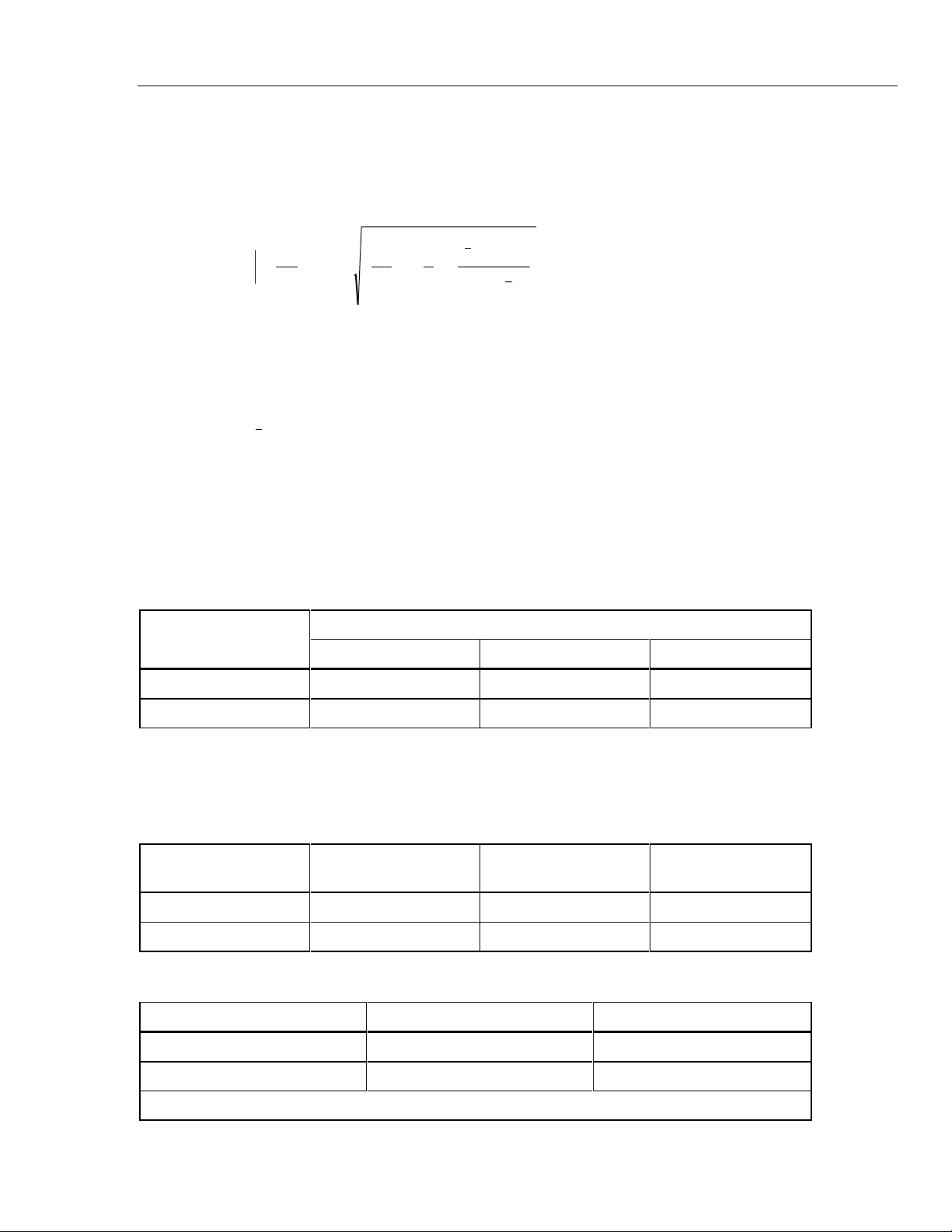
Stability for a given period of time is defined as the output uncertainty minus the
calibration uncertainty at the 99% Confidence Level. When the output voltage is
characterized by a regression model, stability is given by the following equation:
Specifications
1
2
P
+
b
2.65S
365
S
ra
1
S
1
+−
xPx
()
1
+
+
n
Xjx
2
1
2
−
∑
where b = slope of regression in ppm/year
S1 = standard deviation about the regression (SDEV)
Sra = SDEV of data filtered with 7-day moving average filter (MAF)
P = Period of time under consideration in days
x = mean time for regession data
n = 180 period (typically 2 meassurements per day)
Xj = jth period
X1 = time at beginning of data
Each data point for the computation of the regression parameters is the average voltage
of 50 readings taken in a 50-second measurement period.
Stability for the 732B outputs at 23 ±1°C is specified as follows:
Output Voltage
30 Days 90 Days 1 Year
10V 0.3 0.8 2.0
Stability (± ppm)
1.018V 0.8 NA NA
Noise at the Output Terminals
Output noise is specified for both day-to-day observations and for short-term
observations. The former is given by the standard deviation of a 90-day regression
model. The latter is in terms of its rms value in a bandwidth as follows:
Output Voltage S1 (± ppm) Sra (± ppm)
10V 0.068 0.05 0.06
1.018V 0.1 NA 0.03
Output Current and Limits
Output Voltage Output Current Limit Output Impedance
10V 12 mA (Note) ≤ 1 mΩ
1.018V 20 pA ≤ 1 kΩ
Note: Limit output current to ≤ 0.1 mA to realize 72 hour battery operation.
Noise (0.01 Hz to 10
Hz (± ppm rms)
1-7

732B/734A
Instruction Manual
Output Adjustability
Retrace (Hysteresis) Error
Stabilization Time Requirements
- 10V: 0.15 ppm resolution
- 1.018V: Set at nominal ±1 mV. No adjustment is provided.
The 10V adjustment is done with a set of four decade-control switches with a range of at
least 4 mV.
The following table shows the change in 10V output voltage following a power outage
(with the battery turned off) with temperature held constant in the normal operating
range.
Period that Power is Turned Off Change in 10V Output Value
10 minutes or less ≤ ±0.1 ppm
10 minutes to 24 hours ≤ ±0.25 ppm
The following information specifies the warmup times required after ac line and battery
power has been turned off. The IN CAL indicator will be off, and recalibration will be
necessary. The previously specified retrace error specification can be used in the case of
brief power interruptions.
With no power interruption: No stabilization time is required after moving into
another environment.
Power off for less than 1 hour: 1-hour warmup required
Power off for 1 to 24 hours: 24-hour warmup required
Electromagnetic Compatibility
This instrument is designed to operate in Standards Laboratory environments where the
radio frequency (RF) environment is highly controlled. If used in environments with
field strengths >0.18 V/m, there could be errors in measurements.
Temperature Coefficient (TC) of Output
In the temperature range of 15°C to 35°C, the magnitude of the TC is bounded by the
following:
- 10V Output: TC ≤ 0.04 ppm/°C
- 1.018V Output: TC ≤ 0.1 ppm/°C
1-8
Load Regulation
10V Output Load Change Maximum 10V Output Change
0 mA to 12 mA (no load to full load) ±1 ppm
0 mA to 2 mA ±0.1 ppm
Introduction and Specifications
Line Regulation
The outputs will change no more than 0.05 ppm for any 10% line voltage change or for
the entire operating range of the battery.
Output Protection
All outputs can be shorted indefinitely without damage to the instrument. The 10V
output can withstand voltages from other sources as follows:
1. For voltages ≤ 220V dc, the unit is protected for up to 50 mA continuous current.
2. For voltage ≤ 1100V dc, the unit is protected for up to 25 mA continuous current or
up to 0.6 joules for short periods of time.
Environment
Temperature Range Relative Humidity Altitude
Normal Operation 15°C to 35°C 15% to 80% 0 to 6,000 ft
Safe Operation 0°C to 50°C 15% to 90% 0 to 10,000 ft
Specifications
1
Storage (With battery
removed)
-49°C to 50°C Noncondensing 0 to 40,000 ft
Compliance to Standards
ANSI/ISA-S82
CSA C22.2 #231
IEC348
IEC 1010
UL 1244
Line Power Requirements
Line voltage is accepted in the two ranges 90 to 132V and 180 to 264V, at 47 to 63 Hz as
shown in the table below. AC line current at 120V ac is 0.13A.
732B Line Voltage Setting Line Voltage Accepted Frequency Accepted
100V 90 to 110V 47 to 63 Hz
120V 108 to 132V 47 to 63 Hz
220V 180 to 235V 47 to 63 Hz
240V 225 to 264V 47 to 63 Hz
Battery Operation
When fully charged, the internal batteries will operate the 732B for a minimum of 72
hours at 23 ±5°C, with 0 to 0.1 mA current drain at the 10V output. Model 732B-7001
contains the same battery and charger as Model 732B.
1-9
732B/734A
Instruction Manual
Charging Time
External DC Input
Isolation
Guard and Ground Terminals
The batteries are rechargeable in less than 36 hours with a self-contained automatic
battery charger.
A rear panel input for external 12 to 15V dc allows for powering the 732B indefinitely.
The dc source must be rated for 300 mA or more.
The resistance from any of the 732B binding posts to earth (chassis) ground or to ac line
power is greater than 10,000 MΩ shunted by less than 1000 pF.
Chassis ground connections are provided on both the front and rear panels. Access to the
internal guard is provided by a front panel binding post.
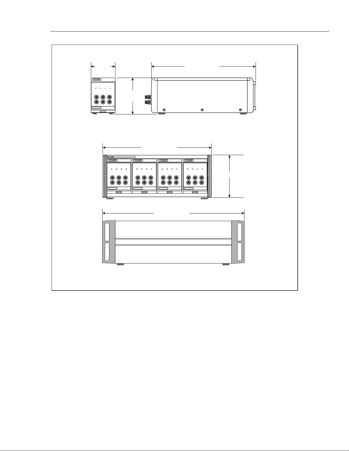
Mechanical Specifications
Model 734A* Model 732B* Model 732B-7001
Height 17.8 cm (7.0 in) 13.4 cm (5.28 in) 13.4 cm (5.28 in)
Width 43.2 cm (17.0 in) 9.8 cm (3.85 in) 9.8 cm (3.85 in)
Depth 50.3 cm (19.8 in) including handles 40.6 cm (16.0 in) 40.6 cm (16.0 in)
Weight 30.4 kg (67 lb) 5.91 kg (13 lb) 5.91 kg (13 lb)
Refer to Figure 1-1.
1-10
Introduction and Specifications
Specifications
1
9.8 cm
(3.85 in)
DC STANDARD
AC PWR IN CAL CHARGE LOW BAT
10V 1.018V CHASSIS
SERIAL NUMBER
GUARD1.018V COM10V COM
734A DC REFERENCE STANDARD
732B DC STANDARD
AC PWR IN CAL CHARGE LOW BAT
10V 1.018V CHASSIS
SERIAL NUMBER
13.4 cm
(5.28 in)
732B DC STANDARD
GUARD1.018V COM10V COM
43.2 cm (17.0 in)
AC PWR IN CAL CHARGE LOW BAT
10V 1.018V CHASSIS
GUARD1.018V COM10V COM
SERIAL NUMBER
732B
732B DC STANDARD
AC PWR IN CAL CHARGE LOW BAT
10V 1.018V CHASSIS
GUARD1.018V COM10V COM
SERIAL NUMBER
50.3 cm (19.8 in)
40.6 cm (16.0 in)
732B DC STANDARD
AC PWR IN CAL CHARGE LOW BAT
10V 1.018V CHASSIS
GUARD1.018V COM10V COM
SERIAL NUMBER
17.8 cm (7.0 in)
734A
Figure 1-1. Mechanical Specifications
k1i.eps
1-11

732B/734A
Instruction Manual
1-12

Chapter 2
Installation
Title Page
2-1. Introduction............................................................................................ 2-3
2-2. Unpacking and Inspection...................................................................... 2-3
2-3. Selecting Line Voltage and Accessing the Fuse.................................... 2-4
2-4. Connecting to Line Power...................................................................... 2-5
2-5. Installing a 732B or 732B-7001 in a 734A-7001 Instrument Enclosure 2-5
2-1

732B/734A
Instruction Manual
2-2
Installation
Introduction
Introduction 2-1.
This section provides instructions for the following:
• Unpacking
• Installation
• Selecting line voltage
• Checking or replacing the fuse
• Connecting to line power
Because this section explains fusing and operating environment requirements, you
should read this section before operating the standard. Section 3 contains instructions for
operating your standard.
Unpacking and Inspection 2-2.
The 732B and 734A are shipped in a container that is specially designed to prevent
damage during shipping. However, you should inspect the standard carefully for
damage, and immediately report any damage to the shipper. Instructions for inspection
and claims are included in the shipping container. If you need to reship the 732B, refer to
Service and Reshipment Information in Section 1.
2
If you ordered your 732B with calibration option 732B-000 or 732B-100, the standard is
shipped hot (under battery power) to maintain the state of calibration. Verify that the IN
CAL indicator is lit. Immediately refer to the fusing and line voltage instructions in this
section, and plug the standard into ac line power.
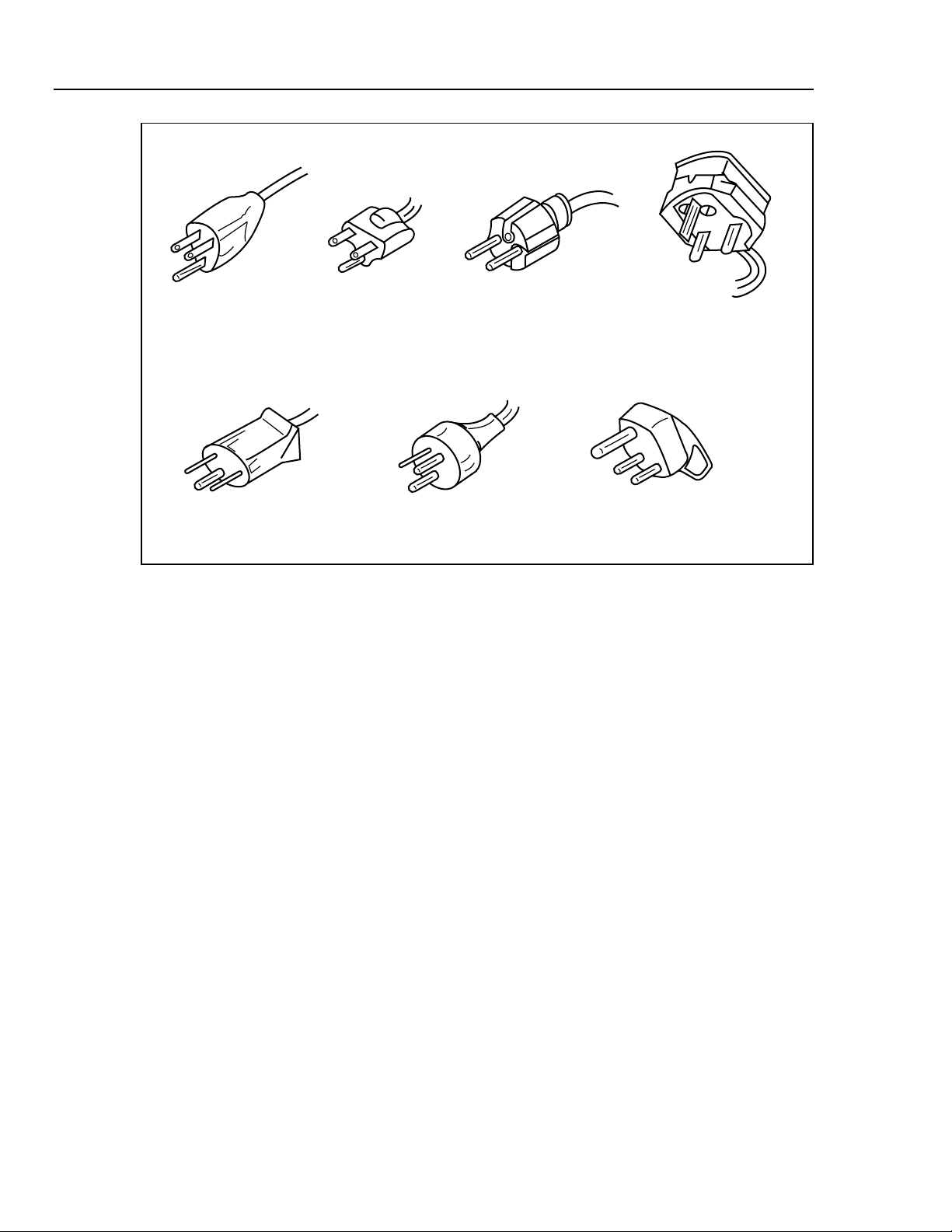
Accompanying the standard should be an ac line power cord appropriate for your
country. Line power cords available from Fluke are listed in Table 2-2 and illustrated in
Figure 2-1. If you have any questions about the contents of the carton you are unpacking,
contact the nearest Fluke Service Center. (A List of Service Centers is located in
Appendix A of this manual.)
For more information about calibration options, refer to Section 1. If a verification test is
required for your acceptance procedures, refer to Section 5 for instructions.
Table 2-1. Standard Equipment
Item Model or Part Number
AC Line Cord (See Table 2-2 and Figure 2-1)
732B/734A Instruction Manual 871723
Table 2-2. AC Line Cords Available for Fluke Instruments
Type Voltage/Current Fluke
North American 120V/15A LC-1
North American 240V/15A LC-2
Universal Euro 220V/16A LC-3
United Kingdom 240V/13A LC-4
Switzerland 220V/10A LC-5
Australian 240V/10A LC-6
South African 240V/5A LC-7
2-3
732B/734A
Instruction Manual
LC-1 LC-2 LC-3 LC-4
LC-5 LC-6 LC-7
Figure 2-1. Line Power Cords Available for Fluke Instruments
k2f.eps
Selecting Line Voltage and Accessing the Fuse 2-3.
Caution
To avoid blowing the ac line fuse, veri fy the position of the line
voltage selection drum before plugging in the line cord. Rotate
the drum if necessary to match local line power.
Caution
To prevent instrument damage, verify that a 1/ 4A, 250V FAST
BLOW fuse is installed. No ot her rating or type of fuse is
acceptable.
The ac input module on the rear panel has four line voltage settings: 100V, 120V, 220V,
and 240V. Each voltage setting has a voltage tolerance of ±10% and accepts line
frequencies of 50 or 60 Hz.
To select line voltage and verify the fuse, or to replace the fuse, refer to Figure 2-2, and
proceed as follows:
2-4
1. Disconnect the ac line cord from the wall outlet and the rear panel.
2. Using a small screwdriver, pop open the line voltage selection module door from the
top.
3. Using the screwdriver, pry the tab of the fuse holder to slide out the fuse holder.
4. Verify the fuse type and rating using the data on the rear panel or Figure 2-2, and
replace it.

Installation
Connecting to Line Power
5. If you need to change the line voltage setting, remove the drum and rotate it so that
the desired voltage is facing outward. Replace the drum.
6. Close the line voltage selection module door. Verify that the line voltage you
selected is showing through the window.
Connecting to Line Power 2-4.
Warning
To avoid electric shock while charging or usi ng t he st andard
with the line cord plugged in, connect t he f act ory supplied,
three-conductor line power cord to a properly grounded power
outlet. Do not use a two-conductor adapt er or ext ension cord to
open the protective ground connection.
Caution
To avoid loss of the state of calibrat ion in case of ac power
interruption, set the BAT swit ch to A (on). This enables battery
backup power.
2
After verifying that the line voltage setting and fuse are correct, make sure the battery
switch is in the position. Connect the line cord to the rear panel ac input plug, and
plug the line cord into a properly grounded three-prong outlet. After 2 hours, place the
battery switch in the A position. Verify that the AC PWR indicator is lit. If it is not,
check for an open fuse. In case of further difficulty, refer to Section 5 for
troubleshooting information.
The 732B and 732B-7001 are IEC Safety Class I (grounded enclosure) instruments, and
must be properly connected to earth ground when plugged into ac line power. When the
ac line cord is plugged into a properly grounded three-prong outlet, the safety ground
path for the battery charger is through the line cord ground lead.
Note
Refer to Section 3 for additional information about powering the standard
from the ac line or the internal battery.
Installing a 732B or 732B-7001 in a 734A-7001 Instrument Enclosure 2-5.
When you slide a 732B or 732B-7001 into one of the instrument bays in the chassis, it
automatically connects to the ac power bus. The 734A-7001 Instrument Enclosure
provides an ac line power bus only. There is no fuse in the 734A-7001. All fusing and
line voltage selection is done in the installed 732Bs and 732B-7001s.
To install a 732B or 732B-7001 in a 734A-7001 Instrument Enclosure, refer to Figure 23 and proceed as follows:
1. Remove the enclosure ac line cord from line power.
2. Verify that the 732B or 732B-7001 BAT switch is set to l and disconnect line power
from the 732B or 732B-7001.
2-5

732B/734A
Instruction Manual
3. Insert the 732B or 732B-7001 into one of the four instrument bays. Guides along the
bottom and a rear panel alignment stud inside the enclosure ensure correct
installation.
4. When the unit is fully installed, lift and engage the locking lever at the bottom of the
732B or 732B-7001 front panel and finger-tighten the thumbscrew.
5. Prepare and connect cables to the rear panel MONITOR/EXT BAT IN (Model
732B) or BAT OUT (Model 732B-7001) connectors as described in Section 3.
6. Connect the enclosure’s ac line cord to a grounded three-prong ac outlet. All units
installed in the chassis are powered by this line cord.
2-6

Installation
Installing a 732B or 732B-7001 in a 734A-7001 Instrument Enclosure
J502
CAL
RESET
BAT
I
120Vac
MONITOR/EXT BAT IN
O
(SEE MANUAL FOR PINOUT)
CAUTION:
FOR FIRE PROTECTION,
REPLACE ONLY WITH
A 250V FUSE OF
INDICATED VALUE
100/120
T 3/16 (3AG)
220/240
50/60 Hz 66W MAX
FLUKE CORPORATION
MADE IN USA
2
120Vac
CAL
RESET
BAT
I
O
CAUTION:
FOR FIRE PROTECTION,
REPLACE ONLY WITH
A 250V FUSE OF
INDICATED VALUE
100/120
220/240
50/60 Hz 66W MAX
FLUKE CORPORATION
MADE IN USA
T 3/16 (3AG)
Figure 2-2. Line Power Label and Fuse Location
k3f.eps
2-7

732B/734A
Instruction Manual
732B DC STANDARD
734A DC REFERENCE STANDARD
10V 1.018V CHASSIS
AC PWR IN CAL CHARGE LOW BAT
732B DC STANDARD
10V 1.018V CHASSIS
AC PWR IN CAL CHARGE LOW BAT
SERIAL NUMBER
GUARD1.018V COM10V COM
732B DC STANDARD
SERIAL NUMBER
AC PWR IN CAL CHARGE
GUARD1.018V COM10V COM
10V 1.018V
1.018V COM10V COM
SERIAL NUMBER
2-8
1.018V CHASSIS
10V
AC PWR IN CAL CHARGE LOW BAT
732B DC STANDARD
Figure 2-3. Installing a 732B or 732B-7001 in a 734A-7001 Instrument Enclosure
10V COM
GUARD
1.018V COM
SERIAL NUMBER
k4f.eps

Chapter 3
Operation
Title Page
3-1. Introduction............................................................................................ 3-3
3-2. Summary of the Features........................................................................ 3-3
3-3. 732B DC Standard Front Panel.......................................................... 3-3
3-4. 732B DC Standard Rear Panel........................................................... 3-3
3-5. 732B-7001 External Battery and Charger Front Panel...................... 3-3
3-6. 732B-7001 External Battery and Charger Rear Panel ....................... 3-3
3-7. 734A-7001 Instrument Enclosure Front Panel .................................. 3-3
3-8. 734A-7001 Instrument Enclosure Rear Panel ................................... 3-3
3-9. Powering the Standard ........................................................................... 3-11
3-10. Setting the BAT Switch ..................................................................... 3-12
3-11. Charging the Internal Battery ............................................................ 3-12
3-12. Powering the Standard from a 732B-7001......................................... 3-12
3-13. Replacing the Internal Battery........................................................... 3-13
3-14. Connecting Cables to the Output ........................................................... 3-14
3-15. Connecting the GUARD and GROUND ........................................... 3-15
3-16. Monitoring Oven Temperature............................................................... 3-16
3-17. Resetting the IN CAL Indicator............................................................. 3-16
3-18. Monitoring The IN CAL Indicator State Remotely............................... 3-16
3-19. Monitoring Long-Term Stability............................................................ 3-17
3-20. Minimizing Error Sources...................................................................... 3-18
3-21. Mechanically Induced Errors............................................................. 3-18
3-22. Thermal EMFs ................................................................................... 3-18
3-23. Output Cable Loading........................................................................ 3-18
3-1

732B/734A
Instruction Manual
3-2

Operation
Introduction
Introduction 3-1.
Information in this section tells you how to operate the 732B and 734A on battery and ac
line power. This section begins with a description of the features of the models covered
in this manual. Instructions for how to power the standard, connect it to other
instruments, and use it to make a voltage transfer follow. Other operating topics,
including minimization of errors during measurements, are included here.
Unless you purchased a calibration option and shipment under battery power (see
Section 1 or a Fluke Catalog for details), the 732B is shipped from the factory with the
internal battery disconnected. (The BAT switch on the rear panel is in the position
marked
After 2 hours, set the BAT switch to the position marked l. Verify that the AC PWR
indicator is lit.
If your 732B was shipped cold, you will need to calibrate it against a
traceable standard as described in Section 5 before you begin using it. For
best results, leave the standard powered for 14 days before you calibrate
and begin using it.
To maintain the state of calibration as a traceable standard, the 732B must continue to
receive uninterrupted operating voltage from the line power or from the internal battery,
which provides approximately 72 hours of off-line operation when fully charged.
). On receipt, connect the ac line cord to line power as described in Section 2.
Note
3
Summary of the Features 3-2.
Please read the following summary of features before you begin using the standard.
Separate illustrations and tables describe the functions and locations of features on the
732B DC Standard, 732B-7001 External Battery and Charger, and 734A-7001
Instrument Enclosure.
732B DC Standard Front Panel 3-3.
Figure 3-1 shows the 732B DC Standard front panel features. Table 3-1 describes these
features.
732B DC Standard Rear Panel 3-4.
Figure 3-2 shows the 732B DC Standard rear panel features. Table 3-2 describes these
features.
732B-7001 External Battery and Charger Front Panel 3-5.
Figure 3-3 shows the 732B-7001 External Battery and Charger front panel features.
Table 3-3 describes these features.
732B-7001 External Battery and Charger Rear Panel 3-6.
Figure 3-4 shows the 732B-7001 External Battery and Charger rear panel features. Table
3-4 describes these features.
734A-7001 Instrument Enclosure Front Panel 3-7.
Figure 3-5 shows the 732A-7001 Instrument Enclosure front panel features. Table 3-5
describes these features.
734A-7001 Instrument Enclosure Rear Panel 3-8.
Figure 3-6 shows the 732A-7001 Instrument Enclosure rear panel features. Table 3-6
describes these features.
3-3

732B/734A
Instruction Manual
11
10
1
732B DC STANDARD
AC PWR IN CAL CHARGE LOW BAT
10V 1.018V CHASSIS
SERIAL NUMBER
2 3 4
5
6
GUARD1.018V COM10V COM
9
7
8
Figure 3-1. 732B DC Standard Front Panel Features
k5f.eps
3-4

Summary of the Features
Table 3-1. 732B DC Standard Front Panel Features
Item Feature Description
1 AC PWR Indicator Lights whenever the standard is connected to ac line power.
2 IN CAL Indicator Goes out to warn you when a loss of calibration may have
occurred. This indicator goes out in response to an excessive
drop in battery voltage or a gross change in oven temperature.
Once you have recalibrated the 732B, you can reset the IN
CAL indicator by pressing the recessed rear panel CAL
RESET switch.
Note
An illuminated IN CAL indicator
is not sufficient, by itself, to
indicate the 732B satisfies the
specifications of section 1-12. See
Calibration label on front of the
732B for calibration due date.
3 CHARGE Indicator Lights when the internal battery is in the constant-current
charging mode. The rear panel BATTERY switch must be in
the | position to charge the battery. When the battery is near
full charge, the CHARGE indicator goes off, and the charging
circuit goes into float-charging mode to complete and maintain
full charge.
Operation
3
4 LOW BAT Indicator Blinks when approximately 5 hours of battery operation time
remains. When LOW BAT blinks, plug the standard into ac
line power as soon as possible to avoid extinguishing the IN
CAL indicator and invalidating the state of calibration.
5 CHASSIS Binding Post A connection point for chassis ground. You can use this
connector when operating on battery power to ground the
chassis to the earth ground point in a system of
interconnected instruments. Another chassis ground
connection is on the rear panel.
6 GUARD Binding Post The connection point for the internal voltage guard. Refer to
the text in this section for instructions on use of the GUARD
connection.
7 1.018V Binding Post The positive connection for the 1.018V output.
8 1.018V COM Binding Post The common connection for the 1.018V output.
9 Serial Number Use this identifier in your correspondence with Fluke.
10 10V COM Binding Post The common connection for the 10V output.
11 10V Binding Post The positive connection for the 10V output.
3-5

732B/734A
Instruction Manual
2
3
1
J502
CAL
BAT
RESET
I
120Vac
7
MONITOR/EXT BAT IN
O
(SEE MANUAL FOR PINOUT)
CAUTION:
FOR FIRE PROTECTION,
REPLACE ONLY WITH
A 250V FUSE OF
INDICATED VALUE
100/120
T 3/16 (3AG)
220/240
50/60 Hz 66W MAX
FLUKE CORPORATION
MADE IN USA
4
6
5
Figure 3-2. 732B DC Standard Rear Panel Features
k6f.eps
3-6

Table 3-2. 732B DC Standard Rear Panel Features
Item Feature Description
Operation
Summary of the Features
3
1 Recessed
CAL RESET
Switch
2 BATTERY Swtich Connects and disconnects the battery from the charger and
3 MONITOR/EXT BAT IN
Connector
4 Fuse Type and Rating
Label
5 CHASSIS Connector A connection point for chassis ground. You can use this
6 Line Cord Plug and Fuse
Holder
If the IN CAL indicator is off and normal 732B operating
conditions are met, pressing this momentary-contact switch for
approximately 4 seconds resets IN CAL. You should calibrate
the 732B before resetting the IN CAL indicator. Normally, a
calibration sticker covers the hole to prevent tampering with
this control.
reference circuitry.
Provides the input/output point for three functions: (1)
powering the standard from external 12 to 15V dc. (2)
Measuring the resistance of the oven temperature thermistor.
(3) Remotely monitoring the IN CAL indicator state.
States the correct fuse type and rating for use in the 100, 120,
220, and 240V settings. Use of an improper fuse defeats the
safety design of the standard and can cause instrument
damage.
connector to ground the chassis to the earth ground point in a
system of interconnected instruments. Another chassis
ground connection is on the front panel. (See the text in this
section for more information about guarding and grounding.)
Houses the ac line fuse and the male three-prong connector
for an IEC-type power cord. The plastic cover fits over the fuse
so it can be accessed only when the power cord is not
connected.
7 Line Voltage Selector Allows selection of four ac line voltage settings, 100, 120, 220,
and 240V, each with a tolerance of 10%. The accepted line
frequencies are 50 and 60 Hz.
3-7

732B/734A
Instruction Manual
2 31
732B-7001 EXTERNAL BATTERY/CHARGER
AC PWR CHARGE LOW BAT
SERIAL NUMBER
4
Figure 3-3. 732B-7001 External Battery/Charger Front Panel Features
Table 3-3. 732B-7001 External Battery/Charger Front Panel Features
Item Feature Description
1 AC PWR Indicator Lights whenever the battery unit is connected to ac line power.
2 CHARGE Indicator Lights when the battery unit is in the constant-current charging
mode. When the battery is near full charge, the CHARGE
indicator goes off, and the charging circuit goes into float-
charging mode to complete and maintain full charge.
k7f.eps
3-8
3 LOW BAT Indicator Blinks when approximately 5 hours of battery operation time
remain. When LOW BAT blinks, plug the battery unit into ac
line power as soon as possible to avoid loss of power to an
attached 732B DC Standard.
4 Serial Number Use this identifier in your correspondence with Fluke.

Operation
Summary of the Features
3
1
BAT
O
I
120Vac
6
BAT OUT
CAUTION:
FOR FIRE PROTECTION,
REPLACE ONLY WITH
A 250V FUSE OF
INDICATED VALUE
100/120
T 3/16 (3AG)
220/240
50/60 Hz 66W MAX
FLUKE CORPORATION
MADE IN USA
2
3
5
4
Figure 3-4. 732B-7001 External Battery/Charger Rear Panel Features
k8f.eps
Table 3-4. 732B-7001 External Battery/Charger Rear Panel Features
Item Fearture Description
1
BATTERY Switch Connects and disconnects the battery from the internal
charger.
2
BAT OUT Connector Provides the connection point for dc output from the battery
unit. Pins 5 and 9 are the dc voltage positive line, and pins 1
and 6 are the dc voltage negative line. All other pins are not
used.
3
Fuse Type and Rating
Label
States the correct fuse type and rating for use in the 100, 120,
220, and 240V settings. Use of an improper fuse defeats the
safety design of the unit and can cause damage.
4
CHASSIS Connector A connection point for chassis ground. You can use this
connector when operating on battery power to ground the
chassis to the earth ground point in a system of
interconnected instruments. Another chassis ground
connection is on the front panel. (See the text in this section
for more information about guarding and grounding.)
5
Line Cord Plug and Fuse
Holder
Houses the ac line fuse and the male three-prong connector
for an IEC-type power cord. The plastic cover fits over the fuse
so it can be accessed only when the power cord is not
connected.
6
Line Voltage Selector Allows selection of four ac line voltage settings, 100, 120, 220,
and 240V, each with a tolerance of 10%. The accepted line
frequencies are 50 and 60 Hz.
3-9

732B/734A
Instruction Manual
1
734A DC REFERENCE STANDARD
732B DC STANDARD
AC PWR IN CAL CHARGE LOW BAT
10V 1.018V CHASSIS
GUARD1.018V COM10V COM
SERIAL NUMBER
732B DC STANDARD
AC PWR IN CAL CHARGE LOW BAT
10V 1.018V CHASSIS
GUARD1.018V COM10V COM
SERIAL NUMBER
3
5 4
Figure 3-5. 734A-7001 Instrument Enclosure Front Panel Features
Table 3-5. 734A-7001 Instrument Enclosure Front Panel Features
Item Feature Description
2
732B DC STANDARD
AC PWR IN CAL CHARGE LOW BAT
10V 1.018V CHASSIS
GUARD1.018V COM10V COM
SERIAL NUMBER
k9f.eps
1 Instrument Bay There are four instrument bays in the 734A-7001 Instrument
Enclosure. Each holds one Model 732B or 732B-7001 unit.
2 AC Power Bus Connector This internal connector automatically mates with the 732B or
732B-7001 rear panel ac power input when you install a 732B
unit into the enclosure.
3 Alignment Pin This alignment pin mates with an alignment hole on the rear
panel of the 732B or 732B-7001. It ensures that the ac line
connectors are aligned.
4 Guide Guides separate each instrument bay.
5 Locking Lever Tighten the screw to lock a 732B or 732B-7001 in place inside
the instrument enclosure.
3-10

Operation
Powering the Standard
3
1
J502
MONITOR/EXT BAT IN
O
(SEE MANUAL FOR PINOUT)
CAUTION:
50/60 Hz 264 W MAX
734A-7001 INSTRUMENT ENCLOSURE
FLUKE CORPORATION MADE IN USA
CAL
RESET
NOTE:
CHECK 732B REAR PANELS
FOR PROPER VOLTAGE SETTING
AND FUSE. BEFORE INSERTING
INTO 734A CHASSIS
I O
BAT BAT BATAT
J502
MONITOR/EXT BAT IN
(SEE MANUAL FOR PINOUT)
CAUTION:
RESET
CAL
I O
CAUTION:
J502
MONITOR/EXT BAT IN
(SEE MANUAL FOR PINOUT)
RESET
MONITOR/EXT BAT IN
CAL
I O
(SEE MANUAL FOR PINOUT)
CAUTION:
2
Figure 3-6. 734A-7001 Instrument Enclosure Rear Panel Features
Table 3-6. 734A-7001 Instrument Enclosure Rear Panel Features
Item Feature Description
1 Access Window This opening provides access to BAT switches and
MONITOR/EXT BAT IN or EXT BAT OUT connectors on
installed 732B or 732B-7001 units.
J502
k10f.eps
2 AC Line Input IEC-type line cord male connector. All fusing is done in the
individual installed 732B units.
Powering the Standard 3-9.
The standard must remain powered continuously to maintain the state of calibration. The
IN CAL indicator goes out if battery voltage has dropped too low, or if there has been a
gross change in oven temperature. Use ac line power at all times unless battery power is
required for moving, shipping, or isolating the standard. Leave the BAT switch set to l so
it is available to power the standard in case of ac power interruption. Leaving the
standard plugged into ac power also maintains full charge on the internal battery.
Switching between line power and battery power has no effect on the standard’s output.
Variations in ac line voltage within ±10% of the line voltage setting change the 10V
output no more than 0.05 ppm. Variations in external dc power within the 12 to 15V
range also change the 10V output no more than 0.05 ppm.
When you remove the line power cord from a grounded receptacle, you can use the front
panel GROUND binding post to connect the chassis to the same earth ground potential
as other instruments in a system.
3-11

732B/734A
Instruction Manual
Setting the BAT Switch 3-10.
Caution
To avoid loss of the state of calibrat ion in case of ac power
interruption, set the BAT switch to ✡ (on). Thi s enables battery
backup power.
Leave the rear panel BAT switch set to l to enable proper battery charging, and to allow
for automatic changeover to battery power in case of ac power interruption or failure.
If you set the BAT switch to
, the 732B requires continuous power from the ac line or
an external dc source to operate. The following situations are the only times it is
recommended that you set the BAT switch to
:
1. When you replace the battery. (Connect the standard to ac line power before you set
the BAT switch to
.)
2. When you want to ship the unit cold (without battery power).
For information about how to set the BAT switch on the 732B when you are using an
external dc source such as the 732B-7001, refer to "Powering the Standard from a 732B-
7001."
Charging the Internal Battery 3-11.
To completely recharge the internal battery in a 732B or 732B-7001 External Battery,
unplug any external dc source from the rear panel. Make sure the BAT switch is set to
the ✢ position, and plug the unit into ac line power. Then return the BAT switch to the l
position and let the instrument charge for 36 hours. The charger applies a constantcurrent charge until the battery is at approximately 90% capacity. During the constantcurrent charge, the CHARGE indicator is lit. The charger then switches to floatcharging mode to complete and maintain the charge on the battery. In float-charging
mode, the CHARGE indicator is extinguished.
The charger circuit is designed to charge the internal battery only. Do not attempt to
charge an external battery through the rear panel MONITOR/EXT BAT IN connector.
Use a separate charger to charge any external batteries, such as the charger inside the
732B-7001 External Battery and Charger.
Powering the Standard from a 732B-7001 3-12.
You can power the standard using an external battery such as the 732B-7001 External
Battery/Charger, or other 12 to 15V dc source that can supply at least 300 mA. You
connect the external dc source through the MONITOR/EXT BAT IN connector. Figure
3-7 shows a pinout diagram of the MONITOR/EXT BAT IN connector. Use this method
if you need to operate the standard on battery power for a period longer than 72 hours.
Or, if the preferred power source is 12 to 15V dc, you can use this method to power the
standard permanently.
Leave the 732B BAT the switch set to l to connect the internal and external batteries in
parallel. Each battery is protected from high discharge into the other by current-limiting
varistor. Set the 732B BAT switch to
this switch position, an external dc source connected to the MONITOR/EXT BAT IN
input continues to power the 732B, but is isolated from the 732B’s internal battery.
To power the standard using the 732B-7001, proceed as follows. Use a similar procedure
for any other 12 to 15V source.
to isolate the internal and external batteries. In
3-12
1. Apply ac line power continuously to the 732B and the 732B-7001 during steps 2
through 7 of this procedure.

Powering the Standard
2. Verify that the BAT switches on both the 732B and 732B-7001 are set to l.
3. Charge the 732B and 732B-7001 for at least 36 hours.
Operation
3
4. Switch both BAT switches to
.
5. Fabricate and connect a cable with a 9-pin connector on each end so that the battery
output from the 732B-7001 is connected to the external dc input of the 732B. Refer
to Figures 3-7 and 3-8 for the connector pinouts.
6. Set the 732B-7001 BAT switch to l to enable its output.
7. Set the 732B BAT switch to l to connect the batteries in parallel.
8. After the ac line power to both the 732V and the 732B-7001 is turned of, the 732B
can be powered by battery for at least 130 hours.
Replacing the Internal Battery 3-13.
If the battery fails to switch from constant-current charging mode to float-charging
mode, either the charger is defective or the battery needs replacement. For preventive
maintenance, it is recommended that you have the battery replaced every 18-24 months
to ensure 72-hour battery backup time. Refer to Section 5 for how to obtain the correct
battery type and for the procedure to replace the battery.
PIN
NUMBER
DESCRIPTION
EXT BAT COMMON
1
EXT COMMON FOR IN CAL
2
EXT +5 VDC FOR IN CAL
3
OVEN TEMPERATURE THERMISTOR A
4
EXT BAT +
5
2
1
345
7
6
Figure 3-7. 732B MONITOR/EXT BAT IN Connector Pinout
9
8
EXT BAT COMMON
6
EXT IN CAL SIGNAL (ASSERTED HIGH)
7
OVEN TEMPERATURE THERMISTOR B
8
EXT BAT +
9
k11f.eps
3-13

732B/734A
Instruction Manual
PIN
NUMBER
NOT USED
12 3 45
876
9
NOT USED
Figure 3-8. 732B-7001 BAT OUT Connector Pinout
DESCRIPTION
EXT BAT COMMON
1
BAT +
5
EXT BAT COMMON
6
BAT +
9
k12f.eps
Warning
To avoid explosion or fire, be careful not to short t he bat t ery
terminals during battery replacement. Only qual i f ied personnel
should replace the battery.
Connecting Cables to the Output 3-14.
Caution
To avoid cracking or jamming the plastic bi ndi ng post
insulators, tighten them only with finger pressure. Do not use
tools.
Shielded test leads should be used for connecting anything to the standard output binding
posts. You can use banana plugs, spade lugs, or bare wire to attach cables to the binding
posts. The best choice is shielded cables with low-thermal emf connectors such as Fluke
Model 5440-7002 Low Thermal Cables. See "Thermal EMFs" further on in this section
for more information. Figure 3-9 shows the cable connections for applying the 10V
source required by the 5700A during its calibration procedure.
3-14

Operation
Connecting Cables to the Output
3
732B DC STANDARD
AC PWR IN CAL CHARGE LOW BAT
10V 1.018V CHASSIS
SERIAL NUMBER
732B
GUARD1.018V COM10V COM
Figure 3-9. Typical 732B Cable Connections
5700A
OUTPUT
HI
LO
HI
AUX
CURRENT
SENSE
V A
ΩΩ
V
GUARD
WIDEBAND
HI
LO
GROUND
NOTE:
GUARD IS CONNECTED TO
GROUND AT ONLY ONE
PLACE.
k13f.eps
Connecting the GUARD and GROUND 3-15.
Note
Spurious currents in the COM (common) wires will degrade measurements
at the accuracy level of the 732B. Make sure the GUARD terminals of all
interconnected instruments are tied to earth ground at one point and one
point only in the system, and all LO or COM terminals are tied to GUARD
at only one point in the system.
Use the GUARD connection when any of the following conditions exists:
1. When a potential exists between equipment and a power line ground.
2. When you use long connection leads to connect a high-impedance load.
3. When you are operating the standard in a high EMI environment.
4. To avoid the effects of electrostatic charge buildup on people.
The GUARD is an electrical shield around the sensitive analog circuitry, insulated from
chassis ground and the rest of the standard. The GUARD provides a low-impedance path
for common-mode noise and ground currents. The guard eliminates the chance of ground
currents in the signal leads caused by plugging the line cord into an ac outlet at a
different ground potential than the chassis ground of the interconnected instruments.
Ground currents can occur if instrument guards are not connected properly, resulting in
annoying and often subtle measurement errors. The basic rule is, in any system of
measurement instruments, the guards within all instruments should be grounded at one
and one point only. Circuit common (the 10V COM or 1.018V COM) should be
electrically connected to the other instrument guards at one and only one point as well,
3-15

732B/734A
Instruction Manual
preferably at the same location the guards are grounded. If an instrument in the system
has a grounded input or output, select it as the common earth ground point for all guards
in the system.
Figure 3-9 shows a connection to the GUARD binding post. The GUARD is used in that
setup to prevent spurious ground currents from degrading the accuracy of the
measurement taking place.
Note
For best results, connect GUARDS to GROUND in a star configuration.
Connect a separate lead between each instrument’s GUARD to the common
GROUND. Do not connect GUARDS in a daisy-chain configuration.
With line power disconnected, you can confirm the integrity of your guarding and
grounding scheme by checking each instrument with an ohmmeter to find hidden or
internal connections between guard, common, and ground. If you have any question
about proper guarding and grounding, draw a guarding diagram for your system of
instruments, and make sure all instrument guards are tied together and grounded at only
one point.
For more information about grounding and guarding, suggested references are
Grounding and Shielding Techniques in Instrumentation, by Ralph Morrison, 1977,
John Wiley & Sons; and Noise Reduction Techniques in Electronic Systems by Henry
W. Ott, 1976, John Wiley & Sons.
Monitoring Oven Temperature 3-16.
As shown in Figure 3-7, MONITOR/EXT BAT IN pins 4 and 8 connect to the two
terminals of the oven temperature thermistor. To monitor the oven temperature, measure
the resistance between these two pins. The nominal resistance at normal operating
temperature is between 36.5 kΩ and 42.5 kΩ. The resistance should change with time by
no more than 900Ω per year. The TC (temperature coefficient) of the thermistor is
approximately 2 kΩ per °C.
You will be able to use this measurement to gain confidence that oven temperature
regulation is working during changes in ambient temperature. Your observations of the
thermistor resistance will reveal when the ambient temperature is too extreme for the
oven temperature regulation circuitry to work properly.
Resetting the IN CAL Indicator 3-17.
If the IN CAL indicator is off, the 732B may not meet its specifications listed in Section
1. The indicator goes off if power to the battery voltage has dropped too low, or if the
oven temperature has gone too high or too low. If IN CAL trips off, you will need to
recalibrate the 732B, or verify its output before you reset the IN CAL indicator. Refer to
Section 5 for the procedure to calibrate the standard and reset the IN CAL indicator.
Monitoring The IN CAL Indicator State Remotely 3-18.
As shown in Figure 3-7, three of the MONITOR/EXT BAT IN pins are connection
points for monitoring the state of the IN CAL indicator. Figure 3-10 illustrates the IN
CAL status output circuit inside the 732B. Proceed as follows to use this connector to
remotely monitor the IN CAL indicator:
3-16
1. Connect an external +5V logic level to pin 3 (common to pin 2).

Monitoring Long-Term Stability
2. With a 10 kΩ pullup resistor between pins 3 and 7, monitor the TTL-level signal on
pin 7 with respect to pin 2. A high state on pin 7 corresponds to the front panel IN
CAL indicator being lit. A low state on pin 7 corresponds to the front panel IN CAL
indicator being off.
+11.5V
3
7
2
+5V
10k
IN CAL (H)
COMMON
5.95
IN CAL (H)
+V
CC
Operation
V
cal
3
Figure 3-10. IN CAL Status Output Circuit
k14f.eps
Monitoring Long-Term Stability 3-19.
You can determine the long-term stability of the standard by periodically comparing the
output voltage to a known reference standard and plotting the difference on a control
chart. Output voltage drift, with respect to the legal volt, may be positive or negative and
is a characteristic of the individual 732B. Accumulated test data have shown that, once
established, the measured drift is generally linear, provided the instrument continues to
receive uninterrupted operating power. When drift rate is established, extrapolations of
output voltage are possible, and allow certification of the standard with lower
uncertainty than is obtainable from the stability specifications alone.
A convenient method of performing the needed periodic calibration is to use the Fluke
Direct Voltage Measurement Program, Option 732B-200 (described in Section 1 and the
Fluke Catalog), which provides calibration against a traceable reference standard in your
own laboratory.
Note
A paper has been published that describes a technique for characterizing
drift rate of solid state dc voltage references. Refer to "The Fluke Direct
Voltage Maintenance Program," by Les Huntley, published in the
proceedings of the 1984 Measurement Science Conference.
Due to the possibility of undetected damage or malfunction, there is a risk involved in
relying completely on any single standard. This risk is reduced significantly by using
two or more independent standards (with frequent intercomparisons) to ensure that all
are stable within the range of expected normal deviations. An added advantage of having
multiple, independent standards is the opportunity to use a statistical average of the
individual outputs. You can use multiple 732B 10V outputs, as obtained with model
734A, in this way to gain statistical improvements of your standard’s uncertainty
specification.
3-17

732B/734A
Instruction Manual
Minimizing Error Sources 3-20.
Mechanically Induced Errors 3-21.
Thermal EMFs 3-22.
You can inadvertently defeat the low uncertainty of the 732B output if you do not pay
proper care to avoidable error sources. Errors can occur from the effects of thermal emfs,
lead and connection resistance, and other sources.
Note
Most importantly, always repeat measurements until you are satisfied that
the results are repeatable relative to the specification being measured.
To avoid changing connector contact resistance and degrading the measurement, do not
change the stresses on the connectors or cables. Try not to move, jostle, or vibrate the
standard or any attached equipment during measurements.
When dissimilar metals at different temperatures come into contact, a thermal voltage is
induced. Thermal voltages can exceed 10 µV. All it takes to induce a thermal emf error
and adversely affect a measurement is to briefly touch and thereby warm a connector or
binding post. Typically, it takes five minutes to thermally stabilize a connection after it
has been touched. In addition, use the following techniques to avoid thermal emf errors:
1. Use the Fluke 5440A-7002 Low Thermal EMF Cable Set.
2. Use #24 AWG or larger, bare copper, Teflon\R-insulated connecting wires. It is
preferable to use shielded, twisted pair cable. Avoid splices.
3. Avoid the use of ordinary, nickel-plated, banana plugs for equipment
interconnections. Use metals that have small thermal emf’s with respect to copper.
4. Use low thermal emf copper spade lugs. Crimp the lug onto the wire and solder the
connection. Loosen the top of the binding post, insert the lug, and tighten the
binding post on the lug with fingers only.
Output Cable Loading 3-23.
The assigned value of the 10V output is guaranteed at the binding posts. A voltage drop
in test leads can cause a loading error. Refer to Figure 3-11. In this example, the 1 kΩ
load sees a 2 mV degradation of the 10V output. To reduce loading errors in applications
where low-impedance loads are unavoidable, use lower resistance test leads (shorter and
heavier gauge).
Digital multimeters usually have much higher impedance than 1 kΩ. Most DMMSs have
a 10 MΩ input impedance. On the 20V dc range, Fluke 8840A 8505A, and 8506A
DMMs present a load impedance higher than 10,000 MΩ. For a DMM with a 10 MΩ
input impedance, the loading error would be 0.2 µV. For a DMM with a 10,000 MΩ
input impedance, there is no significant loading error.
3-18

1 k
LOAD
Operation
3
10 mA
0.1
Ω
CABLE
RESISTANCE
– 1 mV +
10V OUTPUT
Minimizing Error Sources
732B DC STANDARD
AC PWR IN CAL CHARGE LOW BAT
10V 1.018V CHASSIS
Ω
– 1 mV +
Ω
0.1
CABLE
RESISTANCE
Figure 3-11. Loading Error Example
GUARD1.018V COM10V COM
SERIAL NUMBER
k15f.eps
3-19

732B/734A
Instruction Manual
3-20

Chapter 4
Theory of Operation
Title Page
4-1. Introduction............................................................................................ 4-3
4-2. Overall Functional Description.............................................................. 4-3
4-3. Model 734A Functional Description ................................................. 4-5
4-4. Model 732B-7001 External Battery/Power Supply ........................... 4-5
4-5. 732B Circuit Description ....................................................................... 4-5
4-6. 10V Reference Circuit ....................................................................... 4-5
4-7. Generating the 1.018V Output....................................................... 4-7
4-8. Biasing the Refamp for Low Temperature Coefficient................. 4-7
4-9. Sense Current Cancellation ........................................................... 4-7
4-10. Buffering of the 10V Output ......................................................... 4-8
4-11. Oven Temperature Controller A4...................................................... 4-8
4-12. A1 Front Panel Assembly.................................................................. 4-8
4-13. Power Supplies and Battery Charger Assembly A5.......................... 4-9
4-14. Overvoltage Protection Circuitry .................................................. 4-9
4-15. Raw DC Power Supply.................................................................. 4-11
4-16. Battery Charger.............................................................................. 4-11
4-17. +11.5V Preregulator ...................................................................... 4-11
4-18. +11.5V Low-Dropout Regulator ................................................... 4-12
4-19. -6V Power Supply.......................................................................... 4-12
4-20. IN CAL Logic................................................................................ 4-12
4-21. LED Drive Logic........................................................................... 4-12
4-22. AC Power to Battery Power Switching Circuitry.......................... 4-13
4-23. Battery Circuit ............................................................................... 4-13
4-24. Rear Panel Connections................................................................. 4-13
4-25. Low-Battery Shutdown Circuitry.................................................. 4-14
4-1

732B/734A
Instruction Manual
4-2

Theory of Operation
Introduction
Introduction 4-1.
This section presents theory of operation for Models 734A, 732B, and 732B-7001. The
section begins with an overall functional description that describes basic theory for each
of the three instrument models covered by this manual. The functional description
explains how Models 734A and 732B-7001 relate to the 732B DC Standard.
Following the functional description is a detailed circuit description of the Model 732B
Standard. An overall 732B block diagram and separate block diagrams for the reference
circuitry and battery charger/ac power supply are supplied. Refer to the schematic
diagrams for the component-level circuit descriptions.
Note
Although theory is provided, no troubleshooting information or parts
breakdowns are provided for components and assemblies inside the oven
(the small box within the foam insulation). In order to guarantee the output
specification, reference assemblies are not repairable. A faulty reference
must be replaced as a whole unit. Refer to Section 6 for part number
identification and ordering information.
Overall Functional Description 4-2.
Model 732B is a highly stable 10V, 12 mA dc power supply to be used as a standards
laboratory primary dc voltage reference. Refer to Figure 4-1 for an overall block
diagram.
The 10V reference circuit can be thought of as a very accurate and stable series regulator
that reduces the +11.5V regulated supply voltage to the accurate and stable output
available at the front panel 10V and 10V COM binding posts.
The heart of the 10V reference is a pretested, selected reference amplifier (Ref Amp) and
a beta string wirewound resistor set. Refer to "732B Circuit Description" for more
details. The reference circuit is inside a temperature-controlled oven. The oven
temperature controller is a voltage-to-temperature closed loop amplifier. The set point is
established by a voltage divider at approximately 6.43V. This 6.43V corresponds to a
temperature of 45°C inside the oven.
A precision thermistor mounted close to the reference amplifier on the Reference Hybrid
(HR1) substrate enables the user to monitor changes in the oven temperature through the
rear panel MONITOR/EXT BAT IN connector. Instructions for using this connector are
detailed in Section 3. At an oven temperature of 45°C, the thermistor resistance is
approximately 41.3 kΩ.
Four front panel indicators show operating status. The Power Supply (A5 Battery
Charger) assembly lights the AC PWR indicator when the 732B is connected to ac line
power. The Power Supply also controls the IN CAL indicator to warn that an excessively
large drop in 11.5V operating voltage or a large change in oven temperature has
occurred.
Another circuit on the Power Supply monitors the battery voltage and controls the LOW
BAT indicator. A timer IC on the Front Panel assembly (mounted on the binding posts)
serves as an oscillator for LOW BAT causing it to blink.
The dual-mode charger lights the CHARGE indicator when in the constant-current
(high-charge) mode. The charger turns off the CHARGE indicator and switches to a
float-charge mode when the battery is charged to approximately 90% capacity. The float
charge completes and maintains full charge.
Refer to "732B Circuit Description" for a component-level circuit description that begins
with the 10V reference circuit and works outward to the oven control and power supply.
4
4-3

732B/734A
Instruction Manual
10V SERIES
BATTERY CHARGER ON LED
BCD SWITCH
10V HI
PASS CIRCUIT
STAGE
10V HI OUTPUT
BOARD
10V COM
COM1
10V BIAS HI
10V INPUT HI
10V SENSE HI
1.018V HI
1.018V HI
10V BIAS LO
10V SENSE LO
10 VOLT
CIRCUIT
REFERENCE
1.018V COM
GUARD
1.018V LO
OVEN
CONTROLLER
TEMPERATURE
GROUND
IN CAL LED
LO BAT LED
AC POWER ON LED
VOLTAGE GUARD
OVEN ASSEMBLY
CHASSIS GROUND
4-4
RECTIFIER
AND FILTER
POWER TRANSFORMER
+11.5V
REGULATOR
BA TTER Y
CHARGER
AND LINE FILTER
AC LINE SWITCHES
AC NEUTRAL
AC LINE
OVEN TEMPERATURE 1A
OVEN TEMPERATURE 1B
K500
PTC
EXT -BATT
POWER ON
WHEN AC
ENERGIZED
NOTE: RELAY
SWITCH
BATTERY
DISCONNECT
PTC
BATTERY
CHASSIS GROUND
-6V
REGULATOR
Figure 4-1. 732B Overall Block Diagram
11.5V
REGULATOR
SENSING. LOGIC AND
COMPARATOR CIRCUITRY
POWER SUPPLY ASSEMBLY
IN CAL LOGIC OUTPUT
(ISOLATED)
k16f.eps

Theory of Operation
732B Circuit Description
Model 734A Functional Description 4-3.
Model 734A consists of four 732B DC Standards installed in a Model 734A-7001
Instrument Enclosure. The 734A-7001 enclosure contains four internal IEC-type ac line
cord connectors and one rear panel IEC-type ac line cord connector. When you slide a
732B or 732B-7001 into one of the instrument bays in the chassis, it automatically
connects to the ac power bus. The 734A-7001 Instrument Enclosure provides an ac line
power bus only. There is no fuse in the 734A-7001. All fusing and line voltage selection
is done in the installed 732Bs and 732B-7001s.
Model 732B-7001 External Battery/Power Supply 4-4.
Model 732B-7001 is a companion battery and charger for use with the 732B when the
there is a requirement for more than 72 hours of portable (battery) operation. The 732B7001 contains the same battery charger assembly (A5) and gelled-electrolyte sealed leadacid battery as the 732B. Theory in this section pertaining to the 732B DC Standard’s
battery charger also applies to Model 732B-7001.
On the 732B-7001, there are no front panel binding posts, and there is no IN CAL
indicator. On the rear panel, there is no CAL RESET hole, and the connector labeled
MONITOR/EXT BAT IN on the 732B is labeled BAT OUT. For rear panel BAT OUT
connector pinout, refer to Figure 3-8 in Section 3.
4
732B Circuit Description 4-5.
Circuits in the 732B are described to the component level in the rest of Section 2 in the
following order:
1. 10V Reference Circuit
2. A4 Oven Assembly
3. A5 Power Supplies and Battery Charger
4. A1 Front Panel Assembly
10V Reference Circuit 4-6.
Refer to Figure 4-2, the block diagram of the 10V reference circuit. Components that
make up the 10V reference circuit are located on the following four assemblies:
• Reference Hybrid (HR1)
• Oven (A4)
• Flex Circuit (A2)
• BCD Switch (A3)
The Reference Amplifier situated on the HR1 hybrid is the most critical part in the 732B
because it forms the basis for the 732B’s exceptional stability specification. It consists of
an NPN transistor in series with a zener diode. When biased properly, the combination
has a very low temperature coefficient.
The reference voltage that the Reference Amplifier generates can vary from 6.5V to 7V
from device to device. The 10V output will drift in response to the Reference Amplifier
voltage drift by the same amount when expressed in ppm. For example, if the Reference
Amplifier has a linear drift rate of 0.1 ppm per month, then its effect on the output will
be to cause the 10V output to drift 0.1 ppm per month. The Reference Amplifier is
located on the Reference Hybrid (HR1) and is identified by the reference designator U4.
4-5

732B/734A
Instruction Manual
+11.5V
10V HI
1.018V HI
1.018V LO
10V LO
Ω
R403
8.823 kΩR404
Q202
10V BIAS HI
10V SENSE HI
10V BETA
Ω
WW
I
R401
WW
I
6.2 k
1.018V
DIVIDER
STRINGWWRESISTOR
1 k
SET
R402
WW
I
Ω
to 180
Ω
10V ADJUST
158
WW
I
10V SENSE LO
10V
10V
+
CIRCUIT
CURRENT
SENSE HIGH
CANCELLATION
2.976V
R3
Z1
+11.5V
–
R4
Z1
Ω
R1
50 k
U1
–
+
7.024V
Z1
C
I
R2
Ω
118 k
Z
I
Z
+I
C
I
U4
REFAMP
Figure 4-2. 10V Reference Circuit Block Diagram
CIRCUIT
CURRENT
CANCELLATION
REFAMP ZENER
Z
I
10V
C
I
CURRENT
SENSE LOW
CIRCUIT
CANCELLATION
k17f.eps
4-6

Theory of Operation
732B Circuit Description
The next major component that is used to generate 10V is the 10V resistor string. This
string (R401 and R402) is located on the Oven assembly. These are the feedback
elements that set the gain to multiply the reference voltage up to 10V. In its simplest
= (V
form, the voltage of the 10V output is expressed by the equation V
o
R401/R402). The value of R401 is always 6.2 kΩ, and given the value of V
)(1 +
ref
, R402 is
ref
wound to the value so that the 10V output equals 10V within ±1 mV.
But because of uncertainties and inaccuracies in these main components, the output
voltage can be as much as ±100 ppm (1 mV) from 10V. A high-resolution adjustment
circuit compensates for differences in components. Four bcd (binary-coded decimal)
switches allow the user to adjust the output in four decade ranges: 0.1, 1, 10, and 100
ppm.
The circuit controlled by the bcd switches is equivalent to an adjustable resistor in series
with the 10V feedback string resistor R402. As this adjustable resistor is varied, the
effective value of R402 varies, which varies the 10V output. This circuit allows the user
to adjust the output with 0.1 ppm resolution over a range of ±220 ppm. The components
that make up the 10V adjustment circuit are a thin-film resistor network (Z401 on the
Oven assembly), a 180Ω wirewound resistor (R405 on the Oven assembly), and resistors
R301 through R306 and SW301 through R304 on the A3 BCD Switch assembly.
4
Generating the 1.018V Output 4-7.
In addition to a 10V output, a 1.018V output is also provided. This output is derived by
resistively dividing down the 10V output. The 1.018V output is specified for close to 0
mA (20 pA) current load. The two resistors of this divider are R403 and R404 on the
Oven assembly. There is no adjustment of the 1.018V output, except by way of the 10V
output adjustment. The 1.108V output is expressed with the equation V
=
o
(10V)(R404)/(R403 + R404).
Biasing the Refamp for Low Temperature Coefficient 4-8.
As mentioned earlier, the Reference Amplifier contains an NPN transistor and a zener
diode in series. The TC (Temperature Coefficient) of the Reference Amplifier is the sum
of the TC of the zener voltage and the transistor base-emitter voltage. The zener voltage
TC is negative and the transistor TC is positive with a value dependent on its collector
current. Each Reference Amplifier is pretested to determine the collector current at
which the two TCs cancel out yielding an overall Reference Amplifier TC very close to
zero.
To generate this same collector current in the standard, a voltage of 2.976V is generated
across thin film resistor Z1-R3 on the Reference Hybrid (HR1). This resistor is
pretrimmed with a laser to the value that results in the correct collector current.
Sense Current Cancellation 4-9.
The purpose of the current cancellation circuits is to source current to or sink current
from components that are referenced to 10V sense low or connected to 10V sense high.
In the absence of the current cancellation circuits, bias current from these components
would flow through the 10V sense high and low lines to return to the power supply
common, degrading the performance of the 10V circuit.
Three different sense current cancellation circuits are used:
1. 10V sense high current cancellation circuit
2. 10V sense low current cancellation circuit
3. Reference Amplifier zener current cancellation circuit
4-7

732B/734A
Instruction Manual
Buffering of the 10V Output 4-10.
Oven Temperature Controller A4 4-11.
The first circuit (U3A, R2, R3, VR2, and Z1-R10 on the reference hybrid) supplies
current to the 10V high side of the 10V beta string resistors. The second circuit (U2B,
R8, R9, and Z1-R8 Z1-R9) sinks current from the 10V low side of the 10V beta string
resistors and Reference Amplifier collector current. The third circuit (U2A, Z1-R5
through Z1-R7, R5, and R6 on the reference hybrid) sinks the current from the anode of
the Reference Amplifier zener. Thin film resistors Z1-R8 through Z1-R10) are laser
trimmed to values that are a function of the Reference Amplifier voltage and collector
current.
The 10V high output stage contains the series-pass components that supply load current
to the binding posts and bias current to the Reference Amplifier, and other critical
circuitry inside the ovenized assembly. The 10V high output stage also contains an
output current-limit circuit that prevents loads from drawing more than 12 mA.
Components for the 10V high output stage are located on the Flex assembly and include
Q201 and Q202, C201 through C204, R201, and CR201.
The oven temperature controller is a voltage-to-temperature closed loop amplifier. The
set point is established by a voltage divider on Z401. The set point voltage is
approximately 6.43V. This corresponds to a temperature of 45°C inside the oven.
U401B serves as a summing junction and amplifier. The setpoint divider, the feedback
thermistor on HR3, and a gain resistor on Z401 form a bridge that is insensitive to
changes in Vcc when the bridge is balanced or close to being balanced.
The feedback element is a precision, stable NTC thermistor. The stability of this element
is critical to the stability of the oven temperature.
U401A acts as a voltage amplifier with a gain of 240. The output of this amplifier feeds
a common-emitter stage where the emitter resistors are the heaters. Q401 is the control
transistor for the heaters and its power dissipation also adds to the power that the heaters
produce.
To provide good thermal coupling, the feedback thermistor is mounted on the back side
of one of the heater substrates, HR3.
RT401 and R412 serve as a temperature sensitive voltage divider that provides a voltage
signal, TEMP-SENSE, that feeds the IN CAL LED logic.
A precision thermistor mounted close to the Reference Amplifier on the Reference
Amplifier substrate enables the user to monitor oven temperature through the
MONITOR/EXT BAT IN connector on the rear panel. (Figure 3-7 shows the connector
pinout.) At an oven temperature of 45°C, the thermistor resistance is approximately 41.3
kΩ.
4-8
A1 Front Panel Assembly 4-12.
The Front Panel assembly contains the following two functional blocks:
1. LED Circuitry
2. Overvoltage Protection Components

Theory of Operation
732B Circuit Description
The LED Circuitry includes the LEDs and the drive circuitry for the following front
panel indicators:
• AC PWR: When lit, this indicates that ac line power is applied to the 732B.
• CHARGE: When lit, this indicates that the battery charger is in the constant current
mode (high level charging) as opposed to the float charge mode.
• IN CAL: Normally lit. This indicator tells the user that the standard oven
temperature is within the limits of 35°C to 55°C and that operating power has not
been interrupted.
• LOW BAT: Normally off. It blinks at a 1 Hz rate when the battery voltage drops
below +11.4V, indicating that the user should immediately plug the standard into ac
line power to begin recharging the battery.
The overvoltage protection circuitry consists of power diode CR104 and "Transzorb"
transient suppressor device VR101. These components are connected between the 10V
and 10V COM terminals and protect the 732B internal circuitry from external
application of voltages higher than 12V. Another layer of protection is provided by a
spark gap from the 10V COM binding post to chassis ground.
The LED circuitry is composed of CR100 through CR103, R100 through R103, U100,
Q100, C100 through C101, and R104 through R106. CR100 through CR103 are the front
panel LEDs. R100 through R103 serve to limit the current through the LEDs. U100,
C100 through C101, and R104 are a 1-Hz oscillator for blinking CR103 (LOW BAT).
Resistors R105 through R106 and Transistor Q100 are used as an inverting switch to
start and stop the oscillator.
4
Power Supplies and Battery Charger Assembly A5 4-13.
Refer to Figure 4-3 and the A5 schematic diagram in Section 7 for the following
discussion. The Power Supply Module (A5) contains several functional circuit groups as
listed below:
1. Overvoltage Protection Circuitry
2. Raw DC Power Supply
3. Battery Charger
4. +11.5V Preregulator
5. +11.5V Low-Dropout Regulator
6. -6V Power Supply
7. IN-CAL Logic
8. LED Drive Circuitry
9. AC to Battery Switching Circuit
10. Battery Circuit
11. Rear Panel Connections
Overvoltage Protection Circuitry 4-14.
The 732B has overvoltage protection circuitry in the event that the user has the ac
voltage select switch set for 100V ac or 120V ac and connects the ac input lines to 180V
ac or greater. In this case, there is circuitry to short the secondary of the transformer and
blow the main fuse in the Line Filter assembly, FL1.
The transformer secondary voltage is first rectified by diodes CR513 through CR516,
and the rectified ac is applied to both CR500 and the series divider composed of VR501,
R500 and R501. If the voltage applied is greater than 43V, then VR501 conducts and the
resulting current causes a voltage across R501 which then gates CR500 to the conducting
state. This shorts out the secondary and blows the primary fuse in the ac filter assembly
FL1. R500, R501, and C500 act as a noise filter to prevent inadvertent gating of CR500.
R500 also acts as a current limiter for VR501.
4-9

732B/734A
Instruction Manual
BATTERY
BATTERY
CHARGER
LED
CIRCUIT
LOW BAT
LED
BATTERY
CHARGER
CIRCUIT
TO A4
OVEN
TO A1
FRONT PANEL
ASSEMBLY
ASSEMBLY
+11.5V
LOW-DROPOUT
RELAY
BATTERY
REGULATOR
LED
IN CAL
CIRCUIT
AC PWR
DRIVE
ON LED
FROM
A4 OVEN
ASSEMBLY
4-10
BRIDGE
RAW DC
RECTIFIER
AND
AC LINE
SWITCH
FILTER, FUSE,
AC
INPUT
+11.5V
PREREGULATOR
– 6V
SUPPLY
PROTECTION
OVERVOLTAGE
OVEN
TO A4
ASSEMBLY
Figure 4-3. A5 Power Supply/Battery Charger Block Diagram
k18f.eps

Theory of Operation
732B Circuit Description
Raw DC Power Supply 4-15.
The basic components of this circuitry are the bridge rectifier composed of CR501
through CR504, capacitor C502, and voltage regulators U500 and U504. The bridge
rectifies secondary ac from the transformer. Capacitor C502 then filters the voltage to
provide raw dc at the input of the three-terminal regulators U500 and U504. Resistor
R558 acts as a bleeder resistor for C502. C504 and C514 provide local decoupling for
U500 and U504 respectively.
Battery Charger 4-16.
The battery charger for the 732B is a dual mode charger. The charger operates as a
constant current source for a fast charge until the battery is approximately 90% charged.
Then the charger circuitry switches to a voltage source for the remainder of the charge
and for a float charge.
Regulator U500 is the central element of the battery charger. When the battery voltage is
below 12V, Q502 is turned off and the U500 circuitry forms a current source controlled
by the value of the parallel resistance of R502 and R503. This is set to charge at a
nominal rate of 234 mA. As the battery charges, the internal impedance of the battery
remains relatively constant until it is about 90% charged. At this point, the internal
impedance starts increasing rapidly, and the voltage of the current source also starts to
increase rapidly. This provides the sense point for a mode switch.
4
Resistors R520 and R521 form a voltage divider for a comparator formed by U501 and
R517 through R519. When the voltage exceeds 14.6V at the battery terminals, the
comparator switches states and turns Q502 on. This converts the U500 circuitry to a
voltage source with a source impedance that reduces the voltage out as the current draw
increases. Thus, when the charger first switches from constant current to voltage, the
charge current is typically 10 to 75 mA, and gradually reduces to typically 5 to 15 mA
when the battery is fully charged. Resistor R518 provides hysteresis in the comparator.
Thus, the comparator doesn’t switch from the float mode back to the constant current
mode until the battery voltage drops below 12.0V. The comparator switches according to
the following:
• Constant I to Float Voltage at 14.6V
• Float Voltage to Constant I at 12.0V
Any time ac power is applied, a transient is injected into comparator U501 pin 6 via
C541. This results in the constant current recharge mode being enabled regardless of the
battery voltage.
+11.5V Preregulator 4-17.
The +11.5V power supply is composed of two regulators. The first is the +11.5V
Preregulator that converts the raw dc into +14.9V nominal. The second regulator
converts this +14.9V or the battery voltage into a precisely controlled +11.5V for the
10V reference circuitry.
The +11.5V Preregulator consists of U504, C514, CR507, CR508, C515, R531, R532,
and C529. The output voltage of adjustable regulator U504 is set by the values of R531
and R532. Capacitor C514 provides local decoupling, CR507 and CR508 protect the
regulator IC (U504), C515 provides ripple rejection, and C529 stabilizes the regulator
loop.
4-11

732B/734A
Instruction Manual
+11.5V Low-Dropout Regulator 4-18.
-6V Power Supply 4-19.
The Low-Dropout Regulator provides an accurate +11.5V to the Reference Amplifier
and Oven Temperature Control circuitry inside the oven. To maximize the battery life of
the standard, it is necessary to have the least voltage drop possible between the battery
and the oven circuitry.
The central component in this circuit is Q504. This is a MOSFET power IC with a drainto-source resistance (when turned on) of approximately 0.3Ω. Thus, with the maximum
oven current of approximately 120 mA, the voltage drop of the regulator is less than
0.04V with the regulator fully on. Transistor Q504 acts as the series-pass element of the
regulator.
IC U505 provides a precision +10V for the reference of the regulator. U506 is the error
amplifier. Resistors R538 and R539 set the regulated output voltage at 11.5V.
The -6V power supply is used for the current cancellation circuit in the Reference
Amplifier and for the Oven Temperature Control circuit. Both of these are inside the
oven.
IC U511 is the central component in the -6V supply. U511 is a switched capacitor
voltage converter with regulator. R552 and R553 in combination with the internal
reference of the IC set the output voltage level.
R566 and C543 filter the switching noise generated by U511.
IN CAL Logic 4-20.
The 732B has an indicator on the front panel for IN CAL. This indicates that the oven
temperature has remained between 35 and 55°C and that the voltage measured at the
battery has not been reduced below 11.2V dc. If the oven temperature is between 35 and
55°C, pressing the rear panel CAL RESET switch resets (lights) the IN CAL indicator.
The IN CAL indicator stays lit unless the oven temperature drifts out of the 35 to 55°C
range, or if battery voltage drops too low. This mechanism monitors for defects in the
oven control, and warns the user when the standard is not considered to be in calibration.
Two comparator circuits determine if the oven temperature is in the proper range. A
thermistor and resistor in a voltage-divider configuration sense oven temperature. (See
the Oven Control theory for more details.) The output of this divider is fed to
comparators U507C and U507D. Comparator U507C is set to trip when T
55°C. Comparator U507D is set to trip when T
is below 35°C.
oven
is over
oven
These two comparators are in a wired-OR configuration with U507B, which detects low
11.5V voltage at the battery. This wired-OR goes to a resettable latch circuit made up of
NAND gates U509.
LED Drive Logic 4-21.
In addition to the IN CAL indicator, there are three other indicators on the front panel:
• AC PWR
• CHARGE
• LOW BAT
4-12
The AC PWR LED is controlled by the voltage at the ADJUST pin of U504. If ac line
power is applied to the standard, there will be approximately 13.5V at the ADJ pin of
U504. This is applied to Q507, which switches voltage to the AC PWR LED.

Theory of Operation
732B Circuit Description
The CHARGE LED is driven by an inverting amplifier Q505. There is an effective AND
function with the ac power and the battery charger mode as follows:
1. If the charger is in the constant current mode, Q502 is biased off.
2. If ac line power is applied to the standard, the voltage at the collector of Q502 is
high (approximately the battery charge voltage), Q505 is ON and the LED is
energized, indicating that the battery charger is in the constant current mode or high
charge rate mode. If there is a mode change or if the ac line power is removed, the
LED goes out.
The LOW BAT LED is controlled by a comparator off the battery terminals. This
comparator senses the voltage of the battery and if the voltage drops below 11.3V, the
LED will begin blinking at a 1-Hz rate. The oscillator circuitry is on the front panel
assembly. The circuitry on the power supply assembly simply turns the oscillator on or
off. The comparator has hysteresis in it such that the comparator "sets" at approximately
11.4V and "resets" approximately 11.6V.
AC Power to Battery Power Switching Circuitry 4-22 .
If the rear panel BAT switch is set to l, and ac line power is removed from the 732B, the
battery is connected to the Low-Dropout Regulator to provide uninterrupted power for
the +11.5V supply.
4
The switching circuitry is composed of relay K500, VR502, and Q503. Under normal ac
line operation, K500 is energized and the battery is isolated from the Low-Dropout
Regulator. As the voltage across VR502 and R534 falls below 13V, VR502 stops
conducting and Q503 turns off. K500 de-energizes, and the battery voltage is applied to
the Low-Dropout Regulator.
Battery Circuit 4-23.
The battery is a 12V 6.5 or 7.0 amp-hour sealed lead acid battery. If the battery is fully
charged, it provides at least 72 hours of standard operation (with 10V output current
limited to ≤0.1 mA) at an ambient temperature of 25°C. The battery is connected to the
power supply assembly by a two-wire cable. There is protection for the battery in the
form of a diode, CR517, and PTC thermistors RT502 (for an external battery) and
RT503 (for the internal battery).
The diode protects the circuitry on the power supply assembly in case the battery leads
are mistakenly reversed. If the leads are reversed, the diode conducts, keeping the
voltage between +12V-BATT and Common to around 0.7V. At the same time, the
current through the PTC thermistor RT503 heats up the thermistor and serves as a
current limit. RT502 serves the same purpose for an externally connected battery. Switch
SW502 disconnects the battery for shipping the standard cold (with operating power
turned off).
Rear Panel Connections 4-24.
There are several input and output connections on the rear panel of the 732B. The most
obvious are the ac line power and GROUND inputs. The rear panel also has an access
hole for actuating the CAL RESET switch and a 9-pin connector labeled
MONITOR/EXT BAT IN. The connector provides for attaching an external battery or
other 12 to 15V dc source, for monitoring the oven temperature, and for remotely
monitoring the IN CAL indicator status. See Figure 3-7 for its pinout. Figure 3-8 shows
the pinout for the rear panel BAT OUT connector on the 732B-7001.
4-13

732B/734A
Instruction Manual
Low-Battery Shutdown Circuitry 4-25.
Sealed lead-acid batteries such as are used in this instrument are very susceptible to
damage and/or decreased capacity if subjected to deep discharge. To prevent this from
occurring, battery power is turned off when the voltage decreases to the level that
coincides with loss of IN CAL.
Comparator U501A (inputs in parallel with comparator U507A). detects loss-of-cal
status when the battery voltage is at a nominal 11.2V. U501 pin 2 switches to the
conducting state (low) and sinks current through the photodiode of optoisolator U514.,
turning on the output transistor of U514. U514 pin 5 drives U516 pin 3, the clock input
of a CMOS D-type flip-flop. U516 pin 1 (Output) goes low and turns off N-channel
MOSFET Q508. With Q508 off, there is no return path to battery (-), and the instrument
is turned off. The only remaining load on the battery is the supply current to U516,
which is less than the self-discharge current of the battery itself.
The battery voltage quickly recovers to approximately 11.5V, but the latching action of
the flip-flop prevents the instrument turning on again. At this point it is necessary to
reconnect the instrument to the ac mains voltage in order to restore operation. This
enables the 15V supply and turns on the photodiode of U515. The resulting high level at
U515 pin 5 sets U516 pin 1 high which then turns Q508 on and normal operation
resumes.
The IN CAL annunciator will be off and can be reset by SW501 only if the oven
temperature is within limits (the time required to reach this condition is dependent on
how long the instrument remained upowered).
4-14

static awareness
A Message From
Fluke Corporation
Some semiconductors and custom IC's can be
damaged by electrostatic discharge during
handling. This notice explains how you can
minimize the chances of destroying such devices
by:
1. Knowing that there is a problem.
2. Leaning the guidelines for handling them.
3. Using the procedures, packaging, and
bench techniques that are recommended.
The following practices should be followed to minimize damage to S.S. (static sensitive) devices.
1. MINIMIZE HANDLING
2. KEEP PARTS IN ORIGINAL CONTAINERS
UNTIL READY FOR USE.
3. DISCHARGE PERSONAL STATIC BEFORE
HANDLING DEVICES. USE A HIGH RESIS TANCE GROUNDING WRIST STRAP.
4. HANDLE S.S. DEVICES BY THE BODY.

5. USE STATIC SHIELDING CONTAINERS FOR
HANDLING AND TRANSPORT.
6. DO NOT SLIDE S.S. DEVICES OVER
ANY SURFACE.
8. WHEN REMOVING PLUG-IN ASSEMBLIES
HANDLE ONLY BY NON-CONDUCTIVE
EDGES AND NEVER TOUCH OPEN EDGE
CONNECTOR EXCEPT AT STATIC-FREE
WORK STATION. PLACING SHORTING
STRIPS ON EDGE CONNECTOR HELPS
PROTECT INSTALLED S.S. DEVICES.
9. HANDLE S.S. DEVICES ONLY AT A
STATIC-FREE WORK STATION.
7. AVOID PLASTIC,VINYL AND STYROFOAM
IN WORK AREA.
PORTIONS REPRINTED
WITH PERMISSION FROM TEKTRONIX INC.
AND GERNER DYNAMICS, POMONA DIV.
Dow Chemical
10. ONLY ANTI-STATIC TYPE SOLDER SUCKERS SHOULD BE USED.
11. ONLY GROUNDED-TIP SOLDERING
IRONS SHOULD BE USED.

Chapter 5
Maintenance
Title Page
5-1. Introduction............................................................................................ 5-3
5-2. Service Information................................................................................ 5-3
5-3. Replacing the Fuse ................................................................................. 5-3
5-4. Cleaning the External Surfaces.............................................................. 5-3
5-5. Calibration.............................................................................................. 5-3
5-6. Preparing for Calibration ................................................................... 5-4
5-7. Preparing for 10V Calibration with Adjustment................................ 5-4
5-8. Calibration with Adjustment.............................................................. 5-6
5-9. Calibration Without Adjustment........................................................ 5-8
5-10. Access Procedures.................................................................................. 5-9
5-11. Initial Access Procedure .................................................................... 5-9
5-12. Replacing the Battery......................................................................... 5-9
5-13. Replacing the Oven Assembly........................................................... 5-13
5-14. Accessing the A5 Battery Charger..................................................... 5-13
5-15. Removing the Power Transformer Assembly.................................... 5-13
5-16. Troubleshooting ..................................................................................... 5-14
5-17. 10V Reference Performance Test...................................................... 5-14
5-18. Troubleshooting the A5 Battery Charger Assembly.......................... 5-14
5-19. Transformer/Rectifier/Filter.......................................................... 5-15
5-20. Battery Charger.............................................................................. 5-15
5-21. +11.5V DC Preregulator................................................................ 5-15
5-22. +11.5V DC Regulator.................................................................... 5-16
5-23. −6V DC Supply ............................................................................. 5-16
5-24. IN CAL LED Logic....................................................................... 5-16
5-1

732B/734A
Instruction Manual
5-2

Maintenance
Introduction
Warning
Servicing described in this section i s t o be done by qual ified
personnel only. To avoid electric shock or fi re, do not service
the 732B unless you are qualified to do so.
Introduction 5-1.
This section explains how to calibrate the 732B and how to do other maintenance tasks.
You can also return the 732B to Fluke for recalibration and certification of traceability to
NIST (National Institute of Standards and Technology, formerly NBS). (See Section 1
for the procedure to obtain service or calibration from Fluke.)
Service Information 5-2.
The 732B is warranted for a period of 1 year on delivery to the original purchaser. The
Warranty is located on the reverse side of the title page at the front of this manual.
Factory authorized calibration and service for Fluke products is offered at various
worldwide locations. A list of Fluke Service Centers is located at the end of the parts
lists in Section 6. Refer to Section 1 for shipping information.
5
Replacing the Fuse 5-3.
Refer to Section 2 for the fuse access procedure.
Cleaning the External Surfaces 5-4.
Caution
To prevent possible damage to the surfaces of the standard, do
not use aromatic hydrocarbons or chlorinated solvents for
cleaning.
When the 732B is properly cared for and kept in a controlled atmosphere, you seldom
need to clean it. However, any contamination, particularly oil, on the instrument can
create leakage paths that can degrade accuracy.
To keep the standard looking like new, clean the case with a soft cloth slightly dampened
with water or a non-abrasive mild cleaning solution that does not harm painted surfaces
or plastics. Do not attempt to clean the interior of the instrument.
Calibration 5-5.
If the IN CAL indicator is off, or if your calibration interval is expiring, use one of the
following procedures to calibrate (assign a value to) the 732B. After you complete
calibration, reset the IN CAL indicator as described further on in this section.
To maintain its status as a traceable standard following calibration, the 732B must
continue to receive uninterrupted operating voltage from the ac line or from the internal
battery. If operating power is interrupted, the front panel IN CAL indicator goes off and
recalibration is necessary.
5-3

732B/734A
Instruction Manual
Preparing for Calibration 5-6.
You have a choice of two 10V output calibration procedures. Both procedures use direct
comparison between your 732B, called the Unit Under Test (UUT), and a certified 732B
or 732A to calibrate the 10V output. In the first procedure, you do not adjust the 732B
under test. In the second procedure, you adjust the 10V output of the 732B under test so
that it is equal to the reference standard. The 1.018V output is divided down from the
10V output, and is not independently adjustable.
Note
Equivalent equipment and methods may be substituted for the following
calibration procedures as long as the equipment and standards used are at
least as accurate as those specified.
Choose either the procedure with adjustment or without adjustment. Table 5-1 lists the
equipment you will need to calibrate the 732B. Before you proceed, leave the 732B
powered on with the BAT switch set to l and the standard plugged into ac line power for
24 hours. This stabilizes the oven temperature and fully charges the internal battery. If
you want to calibrate the 732B without adjusting it, skip to "10V Calibration Without
Adjustment."
Table 5-1. Equipment Required for Calibration
Equipment Manufacturer Minimum Use Specifications
Null Detector Fluke 845AB or 845AR 0.1 µV Resolution
Low Thermal Shielded Test
Leads
Calibrated 10V Reference
Standard
Any NA
Fluke 732B Certified to the uncertainty
required for your laboratory
Preparing for 10V Calibration with Adjustment 5-7.
In this method, you to adjust the 10V output of the 732B during the calibration
procedure. To access the bcd adjustment switches, perform the "Initial Access
Procedure" in this section. The bcd output adjustment switches are located on top near
the front of the instrument as shown in Figure 5-2. Each switch has the numbers 0
through 9 marked on it. Each higher numbered switch setting causes the output voltage
to increment a positive amount.
The switches are labeled to represent the approximate 10V output shift in ppm as
follows:
• Switch "100" (ppm) adjusts the output in increments of approximately 1 mV to 1.5
mV. The usable range of this switch is 0 to 3. Positions greater than 3 are not
implemented and will simply repeat positions 0 through 3.
5-4
• Switch "10" (ppm) adjust the output in increments of approximately 100 µV to 150
µV. The usable range of this switch is 0 to 9.
• Switch "1.0" (ppm) adjusts the output in increments of approximately 10 to 15 µV.
The usable range of this switch is 0 to 9.
• Switch "0.1" (ppm) adjusts the output in increments of approximately 1 µV. The
usable range of this switch is 0 to 9.

CONNECTION:
1. UUT 10V HI TO 845AB INPUT
2. REF 732B 10V HI TO 845AB COMMON
3. UUT 10V LO TO REF 732B LO
4. CHASSIS TO GUARD AND TO 10V
COM @ REF 732B
5. NO CABLE SHIELD CONNECTION TO
845AB GUARD
6. 845AB GUARD TO 845AB COMMON
7. REF 732B GUARD TO REF 732B
CABLE SHIELD
8. UUT 732B GUARD TO UUT 732B
CABLE SHIELD
9. REF 732B CABLE SHIELD TO UUT
732B CABLE SHIELD
INPUT
COMMON
GUARD
BATTERY
O K
10
–
845AB/AR NULL DETECTOR
(LINE POWERED)
2
0
2
4
6
8
2
3
4
6
8
0
1
1
2
3
+
RANGE
MILLIVOLTS
10
3
1
300
100
30
10
3
1
MICROVOLTS
LINE OPR
10
LINE OPR
30
100
VOLTS
BAT CHG
300
1
3
10
30
100
300
1000
POWER
OFF
BAT CHK
BAT OPR
OPR ZERO
ISOLATED OUTPUT
LEVEL
OUTPUT
Maintenance
Calibration
5
REFERENCE 732B
(LINE POWERED)
732B DC STANDARD
10V 1.018V CHASSIS
10V
COM
COM
GUARD1.018V
Figure 5-1. 10V Output Calibration Connections
UUT 732B
(LINE POWERED)
732B DC STANDARD
10V 1.018V CHASSIS
10V
COM
COM
GUARD1.018V
k19f.eps
5-5

732B/734A
Instruction Manual
Calibration with Adjustment 5-8.
The lowest bcd switch setting is "0000" and the highest is "3999" (in the most significant
to least significant bit order). This range of settings represents total adjustment of 400
ppm (4 mV) minimum, with a resolution of approximately 1 µV. Typically, the bcd
setting for an exact 10.0V will range from 1400 to 2200.
Complete the following procedure to standardize the output of the 732B to a Certified
732B. Verify that for the UUT, the 24-hour warmup period on ac line power has been
met. Always set the null detector to ZERO when changing leads.
Proceed as follows to calibrate the 732B:
1. Obtain a certified 732B or 732A to use as the reference standard.
Caution
To avoid cracking or jamming the plastic bi ndi ng post insulators,
tighten them only with fi nger pressure. Do not use tools.
2. Connect the UUT, certified 732B, and null detector as shown in Figure 5-1.
3. Set the OPR switch on the null detector to the ZERO position. Adjust the null
detector for zero on the 3 µV range.
4. Set the null detector to the 30 µV range and the OPR switch to OPR. If the null
detector needle is pegged, set the range to 100 µV.
5. Adjust the 1.0 ppm bcd switch until the null detector reads less than 10 µV positive
or negative.
Note
If the switch reaches "0" and the null detector is more positive than 10 uV,
adjust the 10 ppm bcd switch down one setting. If the 10 ppm bcd switch
is already at "0", adjust the 100 ppm switch down one setting and set the
10 ppm bcd switch to "9". Continue adjusting the 1.0 ppm bcd switch
µ
until the null detector is within 10
If the switch reaches "9" and the null detector is more negative than -10
V.
Note
µ
V,
adjust the 10 ppm bcd switch up one setting. If the 10 ppm bcd switch is
already at "9", adjust the 100 ppm switch up one setting and set the 10
ppm bcd switch to "0". Continue adjusting the 1.0 ppm bcd switch until
µ
the null detector is within 10
V.
6. Set the null detector to the 10 µV range and adjust the 0.1 ppm bcd switch until the
null detector reads less than 3 µV, positive or negative.
7. Set the null detector to the 3 µV range. Set the OPR switch on the Null Detector to
the ZERO position. Readjust the null detector for zero, if necessary.
5-6

Maintenance
Calibration
5
732B DC STANDARD
AC PWR IN CAL CHARGE LOW BAT
10V 1.018V CHASSIS
SERIAL NUMBER
REPLACE AS MODULE
SERVICEABLE PARTS
ONLY, NO USER
10V OUTPUT ADJ.
0.1 1.0 10 100
(PPM)
!
10V OUTPUT ADJ.
0.1 1.0 10 100
(PPM)
GUARD1.018V COM10V COM
CHARGE
LOW BAT
Figure 5-2. Location of 732B Calibration Adjustment Switches
!
k20f.eps
5-7

732B/734A
Instruction Manual
8. Allow the system to stabilize for at least one minute before final adjustment. Adjust
the 0.1 ppm bcd switch for a null indication on the null detector.
Note
If the switch reaches "0" and the null detector is still on the positive side of a
null, adjust the 1.0 ppm bcd switch down one setting. If the 1.0 ppm bcd
switch is already at "0", adjust the 10 ppm switch down one setting and
set the 1.0 ppm bcd switch to "9". Continue adjusting the 0.1 ppm bcd
switch for a null indication on the null detector.
Note
If the switch reaches "9" and the null detector is still on the negative side of a
null, adjust the 1.0 ppm bcd switch up one setting. If the 1.0 ppm bcd
switch is already at "9", adjust the 10 ppm switch up one setting and set
the 1.0 ppm bcd switch to "0". Continue adjusting the 0.1 ppm bcd switch
for a null indication on the null detector.
9. Reverse the HI and LO (positive and negative) leads on the UUT and certified 732B.
10. Set the OPR switch on the null detector to the OPR position and observe the reading.
If the reading does not equal zero, adjust the UUT for one-half of the null detector
reading.
11. Reverse the HI and LO (positive and negative) leads on the UUT and on the
Certified 732B. The null detector should have the same reading as it did at the end
of step 10. If it does not, adjust the UUT for one-half the difference.
12. Repeat steps 9 through 11 until the Null reading does not change when the UUT and
Certified 732B leads are reversed.
13. The residual reading on the null detector equals the sum of the thermal voltages in
the circuit. At this point, the output voltage of the UUT equals the output voltage of
the Certified 732B.
14. If the IN CAL led is illuminated, proceed to step 15. If it is not, depress the switch
inside the RESET hole located on the rear panel.
15. Calibration on the 10V output is complete. Record all test results. Disconnect all
test equipment. Place the top cover on the UUT, securing it with the six screws.
Cover the RESET hole and one of the six screws with tamper-proof calibration seals.
Calibration Without Adjustment 5-9.
Complete the following procedure to standardize the output of the 732B to a Certified
732B. Battery operation of the 732B UUT is preferred. Turn on the filtering of the
8506A.
1. Obtain a certified 732B to use as the reference standard.
Caution
To avoid cracking or jamming the plastic bi ndi ng post insulators,
tighten them only with fi nger pressure. Do not use tools.
5-8
2. Connect the UUT, Certified 732B, and 8506A as shown in Figure 5-1. (Substitute
the 8506A for the 854AB shown in the figure.)
3. Average 8506A readings over a period of at least one minute.

Maintenance
Access Procedures
4. Reverse the HI and LO (positive and negative) leads on the UUT and certified 732B.
5. Average 8506A readings over a period of at least one minute.
6. Subtract the reading in step 5 from the reading in step 3 and divide this difference by
2.
7. To determine the 10V value of the 732B UUT, add the value in step 6 to the 10V
value of the reference.
8. If the IN CAL led is illuminated, proceed to step 9. If it is not, depress the switch
inside the RESET hole located on the rear panel.
9. Calibration of the 10V output is complete. Record all test results. Disconnect all test
equipment. Place the top cover on the UUT, securing it with the six screws. Cover
the RESET hole and one of the six screws with tamper-proof calibration seals.
Access Procedures 5-10.
Procedures to access the battery, the oven assembly, the A5 Battery Charger/Power
Supply, and the power transformer follow. No access procedure is provided for
components and assemblies inside the oven assembly. The oven assembly contains no
user-serviceable parts, and must be replaced as a unit in case of failure. This unit is the
small box inside the foam insulation, and it includes the attached flex circuit.
5
Initial Access Procedure 5-11.
Refer to Figure 5-3 and proceed as follows to remove the 732B cover and prepare to
access internal components:
Warning
To avoid explosion or fire, be careful not to short t he bat t ery
terminals.
1. Remove the ac line cord from the rear panel.
2. Remove the six screws that fasten the top cover to the chassis. Three screws are
located on each side of the instrument cover near the bottom.
3. Lift off the top cover.
Replacing the Battery 5-12.
For preventive maintenance, replace the battery every 18 to 24 months if the 72 hour
battery backup time is important. If the battery fails to switch from high-current charging
mode to trickle voltage mode, either the charger is defective or the battery needs
replacement. Troubleshooting procedures for the A5 Battery Charger are presented
further on in this section.
The correct battery is available from Fluke by ordering Fluke P/N 887042. Refer to
Figure 5-4 and proceed as follows to replace the battery:
5-9

732B/734A
Instruction Manual
3
3
2
POWER TRANSFORMER
3
3
2
A5 ASSEMBLY
1
1
2
1
1
REPLACE AS MODULE
SERVICEABLE PARTS
Figure 5-3. Accessing Internal Components
ONLY, NO USER
(PPM)
10V OUTPUT ADJ.
0.1 1.0 10 100
OVEN ASSEMBLY
!
10V COM
3
GUARD
1.018V COM
SERIAL NUMBER
k21f.eps
3
2
732B DC STANDARD
3
CHASSIS
CHARGE LOW BAT
1.018V
IN CAL
10V
AC PWR
3
5-10

Maintenance
Access Procedures
Warning
Wear eye protection. Use extreme care not to short the battery
terminals. The battery may explode if shorted.
1. Leave the ac power on to maintain calibration. Remove any cables connected to the
MONITOR/EXT BAT IN connector.
5
2. Set the rear panel BAT switch to
3. Remove the six screws that fasten the top cover and remove the cover.
4. Disconnect the 4-pin, 2-wire connector from the battery where it connects to the A5
assembly.
5. Free the ribbon cable that comes from the front panel from its hold-down guides,
leaving it connected to the A5 assembly.
The “IN CAL” indicator on the front panel will no longer be illuminated. This does not
effect the reference if you do not remove the Mains Power from the instrument.
6. Pull off the red battery terminal lead.
7. Remove the four screws that fasten the battery hold-down bracket (which supports
the A5) to the chassis.
8. Wiggle the battery hold-down bracket until it breaks loose from the foam backing.
9. Lift the front edge of the battery hold-down bracket as shown in view A of Figure 5-
4.
10. Pull the battery hold-down bracket forward until it clears the rear bezel, then rotate it
90° and position it in the keyholes as shown in view B of Figure 5-4.
11. Disconnect the black battery terminal lead and lift out the battery.
12. Put a new battery in place.
13. Connect the black battery terminal lead only.
.
14. Slide the battery hold-down bracket in at the rear first as it came out, drop it into
place, and check for pinched wires.
15. Install the four battery hold-down bracket screws loosely first, then tighten them.
16. Reconnect the red battery terminal lead.
17. Reconnect the 4-pin connector from the battery to the A5 assembly. (Verify correct
polarity.)
18. Hook the ribbon cable that comes from the front panel under its two guides.
19. Check all connections for tightness.
20. Reinstall the top cover.
21. Set the BAT switch to the l position.
22. Reset the CAL swithc by pressing the button accessible through the rear panel CAL
RESET hole with an insulated probe.
23. Verify that the IN CAL indicator remains lit.
24. Reconnect ac line power for normal operation.
5-11

732B/734A
Instruction Manual
(BATTERY TERMINAL)
DISCONNECT
RED WIRE
732B DC STANDARD
DISCONNECT
BATTERY CABLE
(4 POSITION 2 WIRES)
REPLACE AS MODULE
SERVICEABLE PARTS
ONLY, NO USER
10V OUTPUT ADJ.
0.1 1.0 10 100
(PPM)
!
CAUTION
TO AVOID LOSS OF
CALIBRATION, LEAVE AC
LINE CORD PLUGGED IN.
KEY STUDS
(2 PLACES)
AC PWR
10V
10V COM
SERIAL NUMBER
IN CAL
CHARGE
LOW BAT
1.018V
CHASSIS
1.018V COM
GUARD
A.
KEY STUDS GO
INTO KEY SLOTS
(2 PLACES)
732B DC STANDARD
10V OUTPUT ADJ.
0.1 1.0 10 100
(PPM)
REPLACE AS MODULE
SERVICEABLE PARTS
ONLY, NO USER
!
BATTERY BRACKET
HOLD DOWN SCREWS
(4 PLACES)
5-12
AC PWR
10V
10V COM
SERIAL NUMBER
IN CAL
CHARGE
LOW BAT
1.018V
CHASSIS
1.018V COM
GUARD
B.
Figure 5-4. Replacing the Battery
k22f.eps

Maintenance
Access Procedures
Replacing the Oven Assembly 5-13.
Refer to "Troubleshooting" to confirm the necessity of replacing the oven (reference)
assembly. Assembled and tested reference assemblies are available from Fluke as P/N
869193. To replace the oven assembly, which contains the 10V reference circuitry,
proceed as follows:
1. Do the steps under "Initial Access Procedure."
2. Disconnect the two cables that are attached to the A5 assembly at the oven assembly.
3. Refer to Figure 5-3 and remove the three screws that fasten the front panel and oven
to the chassis (one on each side and one on the bottom).
4. Remove the four screws (two on each side) that fasten the oven to the front panel
bezel.
5. Remove the oven assembly. Refer to the parts list illustration for the 732B Final
Assembly for further breakdown information.
6. Reverse the steps to install a new oven assembly.
Accessing the A5 Battery Charger 5-14.
5
Proceed as follows to access A5 Battery Charger/Power Supply assembly for
troubleshooting or replacement.
1. Do the steps under "Initial Access Procedure."
2. The component side of the A5 assembly is now accessible for probing if you are
troubleshooting the board.
3. To remove the A5 assembly, disconnect all four cables from the board.
4. Remove the two screws that fasten the U504 and U500 TO-220 packages to the
battery hold-down bracket.
5. Remove the five screws that fasten the A5 assembly to the battery hold-down
bracket.
6. Remove the A5 assembly. Be careful not to lose the four insulators from step 4.
7. When you reinstall the A5 assembly, reinstall the screws through the tabs on U504
and U500 before you reinstall the rest of the screws. Be careful to include the
isolation washers under the tabs.
Removing the Power Transformer Assembly 5-15.
Proceed as follows to remove the power transformer assembly:
1. Do the steps under "Initial Access Procedure."
2. Remove any cable attached to the rear panel.
3. Disconnect the 3-position cable from the power transformer assembly where it plugs
onto the A5 assembly.
4. Remove the three screws that fasten the rear panel and transformer assembly to the
chassis (one on each side and one on the bottom).
5. Slide the rear panel and transformer assembly (still fastened together) slightly back
and out of the way.
5-13

732B/734A
Instruction Manual
Troubleshooting 5-16.
6. Remove the four screws (two on each side) that fasten the rear panel to the power
transformer assembly.
7. Remove the power transformer assembly.
When a problem occurs with the 732B, first verify that the battery is good and that the
line power fuse is intact. Then you need to determine if the problem is in the 10V
reference circuitry or the A5 Battery Charger/Power Supply assembly.
Presented first is a simple performance test for troubleshooting the 10V reference
circuitry. If the 10V reference circuit is faulty, the complete oven assembly must be
replaced as a unit. The reason for this is that repairing the reference circuitry can disrupt
the stability of the standard.
Following the 10V reference performance test is a detailed troubleshooting procedure for
the A5 Battery Charger/Power Supply. If you believe that the reference circuitry is
faulty, review the A5 troubleshooting information first. Make sure that the problem is
not in the A5 assembly before you replace an oven assembly.
10V Reference Performance Test 5-17.
To check for a failure in the 10V reference circuitry, look for any of the following
symptoms (assuming that you have allowed a warmup period of at least 24 hours):
1. The 10V output is further than ±3 mV from 10V.
2. The 1.018V output is further than ±1.5 mV from 10V.
3. When the 10V output is shorted, the short circuit current is greater than 50 mA.
4. The 10V output is excessively noisy with consistent dvm rattle of greater than 5 µV
(using a 6-1/2 or 7-1/2 digit dvm with sampling no faster than 1 per second and with
filtering on).
5. The 1.018V output is excessively noisy with consistent dvm rattle of greater than 2
µV (using a 6-1/2 or 7-1/2 digit dvm with sampling no faster than 1 per second and
with filtering on).
Troubleshooting the A5 Battery Charger Assembly 5-18.
There are six functional circuit groups in the A5 assembly:
1. Transformer/Rectifier/Filter
2. Battery Charger
3. +11.5V Preregulator
4. +11.5V Regulator
5. -6V Supply
6. IN CAL LED Logic
5-14
These groups are linked together but are autonomous enough to be checked
independently on an input/output basis. The following information describes the circuits
where necessary for understanding the troubleshooting method, but not in detail. For a
more detailed circuit description, refer to Section 4. To locate test points and
components, refer to the schematic and parts placement diagrams in Section 7.

Maintenance
Troubleshooting
Transformer/Rectifier/Filter 5-19.
The transformer/rectifier/filter functional group is composed of the transformer
assembly, the overvoltage detect circuit, the rectifier bridge, and the capacitive filter.
The transformer provides a secondary voltage of 25V rms, or about 30V pk.
The best way to troubleshoot this section is to use an oscilloscope at TP501 and at the
secondary input connector J501. The ripple voltage at TP501 should be approximately
400 mV p-p. You can check the overvoltage detect circuit by using a variable ac source
with some current limiting. The overvoltage detect circuit should short out the secondary
when it trips.
Use the following guide to symptoms and possible faults:
Symptom 1: No voltage at TP501
Check: Cable, secondary voltage, diodes CR501-504, C502, C503, or C504.
Symptom 2: Charger puts out approximately 12V dc but will not go higher.
Check: To see that the ac line voltage selector is in the 120V ac position. These
symptoms will occur if the selector is in the 220V ac position and 120V ac is applied.
5
Battery Charger 5-20.
The battery charger is a dual mode charger. In one mode it acts as a current source of
234 mA. In the other mode, it acts as a voltage source with a finite source impedance. IC
U501, pins 6, 7, and 1 act as the sensing comparator for switching between these modes.
If the battery charger doesn’t work correctly, start by removing ac power and the battery
connections and replacing the battery with a 51Ω, 3W resistor or resistor network. Power
the unit with ac and check to see that the voltage across the resistor is consistent with a
current of 234 mA (11.93V dc nominal). This checks the whole current source section of
the circuit.
If the voltage across R502 or R503 is not 1.25V dc in the current mode, first check to see
that SW502 is closed, then check U500 or the protection diode CR505. The sensing
circuit is supposed to switch from the current mode to the voltage mode when the
voltage across the battery is 14.6V dc. This is equivalent to a battery impedance of
62.4Ω. You can simulate this impedance using a variable resistor from 50 to 70Ω, but
make sure the resistor is able to dissipate the required power. If the circuit doesn’t switch
from the current mode to the voltage mode, check the U501 comparator and Q502
switch.
+11.5V DC Preregulator 5-21.
The +11.5V DC Preregulator circuit is a constant-voltage supply set by U504 and
resistors R531 and R532. The output is nominally +14.9V dc. If the voltage is too high,
check resistors R531 and R532, and U504 and CR507.
The battery switch relay circuit should switch the state of relay K500 when the voltage at
the output of U504 falls below about 14V dc. At this point, the zener stops conducting,
and transistor Q503 switches off, thus de-energizing relay K500. Check the trip point of
the relay switching circuit by reducing the voltage. Use either method 1 or 2:
1. Insert a potentiometer in parallel with R532 to reduce the effective resistance of
R532 to reduce the voltage in a controlled manner.
2. Parallel R532 with a 4.12 kΩ resistor. This will drop the voltage to 12V dc.
5-15

732B/734A
Instruction Manual
+11.5V DC Regulator 5-22.
-6V DC Supply 5-23.
IN CAL LED Logic 5-24.
The input and output of the +11.5V dc regulator circuit can be easily checked at TP507
and TP508. The input should be nominally 14.87V dc. The normal range is 14.52 to
15.20V dc. If there is no voltage at the 10V output binding posts, check F501 first. If
okay, check the regulator circuit around Q504. The reference voltage used for this circuit
comes from U505, pin 6 and is +10.00V dc. Check U506 pin 3 to see that the feedback
divider is at the proper ratio, which is V3/V
= 0.870.
out
The -6V dc supply consists almost entirely of U511. Check the -6V output at U511 pin 5
or at J504 pin 6 to verify the output (voltage at J504 pin 6 will be approximately 0.4V
less magnitude due to the drop in R566). If it is bad, first disconnect J504 and recheck
the output. If it is now good, this confirms that something downstream from the cable is
at fault. If still bad, check to see that V
and Common are correct on U511. If they are
cc
correct, replace U511. Also check C524, C525 and C527 to confirm that they are not
damaged.
The IN CAL LED logic is controlled as follows: IN CAL LED(*) = TempHi(*) OR
TempLo(*) OR BattLo(*), where (*) = asserted low.
When the oven temperature is at nominal, TEMP-SENSE is approximately +8.14V dc. If
the oven temperature rises above 55°C, this signal voltage increases to above +9.02V
and a comparator in U507 changes state. Similarly, if the oven temperature falls to below
35°C, the TEMP-SENSE voltage decreases to below +6.98V dc and a comparator in
U507 changes state. If the VBATT line (battery voltage) falls to below +11.16V dc, a
comparator in U507 changes state.
Any of these actions (temperature too high or low or operating voltage too low) cause
the IN CAL LED to go out. You can check each trip condition individually by using a
variable source on the TEMP-SENSE line as follows:
1. Check to see that +10V-REF is very close to 10V. This comes from U505 and
should be quite stable.
2. Check VBATT to see that it is greater than +12V dc.
3. Disconnect J504 and connect a variable dc source to either J504 pin 5 or to TP513.
Vary the source and look at the wired-OR connection at TP512. Make sure you are
checking only one logic variable at a time. If there is a problem with any of these
comparators, replace U507.
The IN CAL LED is latched through the NAND gates in U509. If there is a problem
with this, check SW501 or U509. The external IN CAL indicator, available at J502 on
the rear panel, can be checked by varying the IN-CAL-LED(*) signal line and observing
that Q506 changes state, that current through the optoisolator changes state, and that the
output transistor in the optoisolator changes state. Be sure to use a 10 kΩ pullup resistor
between U513 pin 7 (or J502 pin 7) and U513 pin 8 (or J502 pin 3).
5-16

Chapter 6
List of Replaceable Parts
Title Page
6-1. Introduction............................................................................................ 6-3
6-2. How to Obtain Parts............................................................................... 6-3
6-3. Manual Status Information..................................................................... 6-3
6-4. Newer Instruments ................................................................................. 6-3
6-5. Service Centers....................................................................................... 6-4
6-1

732B/734A
Instruction Manual
6-2

List of Replaceable Parts
Introduction
Introduction 6-1.
This section contains an illustrated list of replaceable parts for the 734A, and 732B. Parts
are listed by assembly; alphabetized by reference designator. Each assembly is
accompanied by an illustration showing the location of each part and its reference
designator. The parts lists give the following information:
• Reference designator
• An indication if the part is subject to damage by static discharge
• Description
• Fluke stock number
• Total quantity
• Any special notes (i.e., factory-selected part)
Caution
* symbol indicates a device that may be damaged by stat i c
A
discharge.
How to Obtain Parts 6-2.
6
Electrical components may be ordered directly from the Fluke Corporation and its
authorized representatives by using the part number under the heading FLUKE STOCK
NO. In the U.S., order directly from the Fluke Parts Dept. by calling 1-800-526-4731.
Parts price information is available from the Fluke Corporation or its representatives.
Prices are also available in a Fluke Replacement Parts Catalog which is available on
request.
In the event that the part ordered has been replaced by a new or improved part, the
replacement will be accompanied by an explanatory note and installation instructions, if
necessary.
To ensure prompt delivery of the correct part, include the following information when
you place an order:
• Instrument model and serial number
• Part number and revision level of the pca containing the part
• Reference designator
• Fluke stock number
• Description (as given under the DESCRIPTION heading)
• Quantity
Manual Status Information 6-3.
The Manual Status Information table that precedes the parts list defines the assembly
revision levels that are documented in the manual. Revision levels are printed on the
component side of each pca.
Newer Instruments 6-4.
Changes and improvements made to the instrument are identified by incrementing the
revision letter marked on the affected pca. These changes are documented on a manual
supplement which, when applicable, is included with the manual.
6-3

732B/734A
Instruction Manual
Service Centers 6-5.
To locate an authorized service center or to contact Fluke, call one of the following
telephone numbers:
USA and Canada: 1-800-44-FLUKE (1-800-443-5853)
Europe: +31 402-678-200
Japan: +81-3-3434-0181
Singapore: +65-
-276-6196
*
Anywhere in the world: +1-425-356-5500
Or, visit Fluke’s Web site at www.fluke.com.
Parts 6-6.
Note 1
This instrument contains a sealed lead battery. Do not mix with the solid
waste stream. Spent batteries should be disposed of by a qualified recycler
or hazardous materials handler. Contact your authorized Fluke service
center for recycling information.
Manual Status Information
Ref or
Option No.
A1 Front Panel PCA 869169 C
A5 Power Supply PCA 869185 G
Assembly Name
Fluke
Part No.
Revision
Level
6-4

Table 6-1. 734A DC Reference Standard
List of Replaceable Parts
Parts
6
Reference
Designator
A732 732B DC STANDARD 869297 4
F1 FUSE,.25X1.25,0.187A , 250V,SLOW 501098 1
H500 S CRE W,PH,P,LOCK,STL,6-32, .250 152140 14
H515 S CRE W,FHU,P,LOCK,SS,6-32, . 250 320093 22
H540 S CRE W,CAP,SCKT,SS, 8-32, .375 295105 20
H565 S CREW,KNURL,SL,CAPT,SS,10-32,1,750 912436 4
H570 RI V ET,BUTTON,NYL,.125,.330 927533 12
MP509 BARREL NUT 868984 4
MP513 INST TOP COVER 869011 1
MP514 INST BOTTOM COVER 869016 1
MP515 REAR PANEL 868989 1
MP516 GUIDE PIN 869029 4
MP520 BOTTOM FOOT, MOLDED, GRAY #7 868786 4
MP524 HANDLE,INSTRUMENT, GRAY #7 886333 4
MP528 SIDE TRIM I NS ERT 878934 2
MP530 CHASSIS ASSEMBLY 878939 1
MP531 SIDETRIM 869052 2
MP533 DECAL, FRONT PANE L 869326 1
MP534 BEZEL BOTTOM,P AINTED 921908 1
MP535 PAWL,PAINTED 921903 4
MP539 BEZEL TOP,PAINTED 921911 1
MP540 SPRING,COIL, EXT,LOOP END,SS,.500m,125 912423 4
MP544 SPRING,COIL, COM P ,SS,1.00,.240 912428 4
TM1 732B/734A INSTRUCTION MANUAL 869321 1
W503 RECEPTA CLE CABLE 921890 1
W504 CORD,LINE,5-15/ IEC,3-18AWG,SVT 284174 1
Description
Fluke Stock
No
Tot Qty Notes
6-5

732B/734A
Instruction Manual
732B DC STANDARD
734A DC REFERENCE STANDARD
10V 1.018V CHASSIS
AC PWR IN CAL CHARGE LOW BAT
732B DC STANDARD
AC PWR IN CAL CHARGE LOW BAT
10V 1.018V CHASSIS
SERIAL NUMBER
GUARD1.018V COM10V COM
732B DC STANDARD
SERIAL NUMBER
AC PWR IN CAL CHARGE
GUARD1.018V COM10V COM
10V 1.018V
1.018V COM10V COM
SERIAL NUMBER
6-6
Figure 6-1. 734A DC Reference Standard
732B DC STANDARD
10V
AC PWR IN CAL CHARGE LOW BAT
1.018V CHASSIS
10V COM
GUARD
1.018V COM
SERIAL NUMBER
k23f.eps

H540
(5 PL)
MP524
List of Replaceable Parts
Parts
6
H500
(2 PL)
H570
(12 PL)
MP539
(4 PL)
MP544
(4 PL)
MP535
H565
(5 PL)
MP524
H540
(5 PL)
H515
(2 PL)
MP530
CHASSIS
ASSEMBLY
MP540
H515
H500
(2 PL)
H500
(2 PL)
Figure 6-1. 734A DC Reference Standard (cont)
(4 PL)
(2 PL)
H509
(4 PL)
734A-5001
(1 of 2)
k24f.eps
6-7

732B/734A
Instruction Manual
H515
(3 PL)
MP513
MP528
MP540
(2 PL)
MP540
(2 PL)
MP524
(2 PL)
MP500
(4 PL)
MP515
H500
MP516
(4 PL)
W503
H540
(2 PL)
MP531
MP530
H540
(3 PL)
MP533
MP531
H515
(3 PL)
MP528
MP514
H515
(3 PL)
6-8
H515
(3 PL)
Figure 6-1. 734A DC Reference Standard (cont)
MP520
(4 PL)
734A-5001
(2 of 2)
k25f.eps

Table 6-2. 732B DC Standard
List of Replaceable Parts
Parts
6
Reference
Designator
A1 * FRONT PANEL PCA 869169 1
A5 * POWER SUPPLY P CA 869185 1
BT401 BATTERY,LEAD-ACID,12V,6.5AH 887042 1
F1 FUSE,.25X1.25,0.187A ,250V,SLOW 501098 1
E001 TERM,RING,#6,26-22AWG,CRIMP,GOLD 832667 1
H112 WA S HER,LOCK,INTRNL,STL,.512ID 641381 1
H146 WASHER,FLAT,BRASS,#8,0.032 THK 631606 5
H174 SCREW,FHU,P,LOCK,SS,6-32,.250 320093 16
H185 SCREW,PH,P,LOCK,STL,6-32,.250 152140 16
H225 SCREW,FH,P,LOCK,STL,4-40,.250 114884 1
H226 SCREW,PH,P,LOCK,STL,4-40,.250 129890 2
H303 SCREW,PH,P,LOCK,STL,6-32,.312 152157 4
H504 SCREW,CAP,SCKT,SS,8-32,.375 295105 2
H618 SCREW,FHU,P,SS,6-32,.312 867234 6
H625 WASHER,SHLDR,NYLON,.118,.250 485417 2
MP100 * REFERENCE MODULE ASSEMBLY 869193 1
MP103 GUARD TOP 878918 1
MP104 GUARD BOTTOM 878921 1
MP106 BEZEL 871819 2
MP107 FRONT PANEL DECAL 871827 1
MP108 FRONT PANEL 871876 1
MP111 GROUND ADAPTER, BINDING POST 882998 1
MP113 INSULATOR,BI NDING POST,FRONT,BLACK 860411 6
MP119 INSULATOR,REA R, BINDING POST,BLACK 860361 5
MP125 BINDING POST-RED 860452 2
MP127 BINDING POST , BLACK 860457 2
MP129 BINDING POST , GREEN 871616 1
MP130 BINDING POST, BLUE 871637 1
MP143 GROUND STRIP,B E CU,SPRING FINGER 370619 1
MP144 CABLE ACCESSORY,CLAMP,ADHESIVE 838300 2
MP151 CABLE TIE, MOUNT,ADHESIVE,0. 19" 565036 1
MP155 WASHER, LOW THERMA L #8 859939 9
MP164 NUT, #8 LOW THERMAL 850334 11
MP196 CORE,BEAD,FERRITE,.562X.25X.53 876979 4
MP228 O-RING,NITRILE N674-70, .208,.070 910815 2
MP307 REAR PANEL 878884 1
MP310 LABEL,BATTERY SWITCH ALERT,732 921978 1
MP314 FLUKE NAMEP LA T E 879770 1
MP315 LABEL,VINYL,1.500,.312 844712 1
MP401 TERMINAL MTG ASSY 878947 1
MP402 BATTERY BRACKE T 878897 1
MP405 CHASSIS ASSEMBLY 878942 1
Description
Fluke Stock
No
Tot Qty Notes
6-9

732B/734A
Instruction Manual
Table 6-2. 732B DC Standard (cont)
Reference
Designator
MP502 HANDLE ARM/RE A R FOOT 871868 2
MP506 TOP COVER, PAI NTE D 871962 1
MP508 HANDLE, PAI NTED 871959 1
MP509 DECAL, CSA 864470 1
MP602 INSUL PT,DIODE,POLYIMIDE,. 130, ,375 887307 2
MP636 FOOT,RUBBER,ADHES,BLK,.50 SQ,.23 THK 887047 4
MP703 OVEN FOAM 871806 1
MP704 FOAM PLUG, INNE R 871801 1
MP705 FOAM PLUG, OUTER 871814 1
MP706 OVEN TOP COVER 869110 1
MP707 TERMINAL EXTE NS I ON 869102 4
T633 TRANSFORMER ASSY 878967 1
TM1 732B/734A INSTRUCTION MANUAL 869321 1
W001 WIRE,TEF ,UL1180,26AWG,STRN,WHT 166991 1
W230 CORD,LINE,5-15/ IEC,3-18AWG,SVT 284174 1
W640 CABLE, BA TTE RY 869198 1
Description
Fluke Stock
No
Tot Qty Notes
6-10

MP1966
A1
(4 PL)
MP155
(5 PL)
MP100
List of Replaceable Parts
Parts
MP164
(4 PL)
6
MP401
MP113
MP125
(6 PL)
MP14
MP111
H113
MP155
(5 PL)
MP119
MP164
(4 PL)
(5 PL)
MP707
(4 PL)
MP125
MP129
MP127
MP127
MP130
MP401 CUTAWAY
FOR VIEWING
Figure 6-2. 732B DC Standard
732B-5001
(1 OF 5)
k26f.eps
6-11

732B/734A
Instruction Manual
H312
MP144
MP151
MP144
A1
(REF)
MP104
(REF)
MP103
H312
MP143
H312
MP104
6-12
732B-5001
(2 OF 5)
k27f.eps
Figure 6-2. 732B DC Standard (cont)

H303
(2PL)
(2PL)
MP502
PART OF
List of Replaceable Parts
MP307
REAR BEZEL ASSEMBLY
H174
(2PL)
Parts
6
H174
(2PL)
H174 (2PL)MP106
MP108
MP106
H174
H174
MP107
T633
(2PL)
(2PL)
MP314
Figure 6-2. 732B DC Standard (cont)
MP315
732B-5001
(3 of 5)
k28f.eps
6-13

732B/734A
Instruction Manual
U500
(2 PL)
H625
(2 PL)
H226
(2 PL)
H312
(2 PL)
A5
MP602
(2 PL)
W640
H312
(2 PL)
H312
(2 PL)
MP402
BT401
MP405
6-14
USE FIXTURE
TO PLACE FEET
Figure 6-2. 732B DC Standard (cont)
MP636
(4 PL)
732B-5001
(4 of 5)
k29f.eps
 Loading...