

Page 1

729/729 FC
Automatic Pressure Calibrator
Users Manual
May 2017
© 2017 Fluke Corporation. All rights reserved. Specifications are subject to change without notice.
All product names are trademarks of their respective companies.
Page 2

LIMITED WARRANTY AND LIMITATION OF LIABILITY
This Fluke product will be free from defects in material and workmanship for three years from the date of purchase. This
warranty does not cover fuses, disposable batteries, or damage from accident, neglect, misuse, alteration, contamination, or
abnormal conditions of operation or handling. Resellers are not authorized to extend any other warranty on Fluke’s behalf.
To obtain service during the warranty period, contact your nearest Fluke authorized service center to obtain return
authorization information, then send the product to that Service Center with a description of the problem.
THIS WARRANTY IS YOUR ONLY REMEDY. NO OTHER WARRANTIES, SUCH AS FITNESS FOR A PARTICULAR
PURPOSE, ARE EXPRESSED OR IMPLIED. FLUKE IS NOT LIABLE FOR ANY SPECIAL, INDIRECT, INCIDENTAL OR
CONSEQUENTIAL DAMAGES OR LOSSES, ARISING FROM ANY CAUSE OR THEORY. Since some states or countries
do not allow the exclusion or limitation of an implied warranty or of incidental or consequential damages, this limitation of
liability may not apply to you.
Fluke Corporation
P.O. Box 9090
Everett, WA 98206-9090
U.S.A.
11/99
Fluke Europe B.V.
P.O. Box 1186
5602 BD Eindhoven
The Netherlands
Page 3

Table of Contents
Title Page
Introduction .................................................................................................................... 1
Contact Fluke ................................................................................................................. 2
Safety ............................................................................................................................. 3
Warnings and Cautions ............................................................................................. 3
Symbols ..................................................................................................................... 6
Standard Equipment....................................................................................................... 8
Buttons ........................................................................................................................... 10
The Display .................................................................................................................... 13
Triple-Function Display .............................................................................................. 17
RTD Connection ........................................................................................................ 18
Pressure Module Connection .................................................................................... 18
Fluke Connect Device Connection ............................................................................ 19
Ports ............................................................................................................................... 20
Download the Fluke Connect® App ................................................................................ 22
Enable the Fluke Connect® App ..................................................................................... 23
i
Page 4

729/729 FC
Users Manual
Setup Menu ................................................................................................................... 24
Manage FC Devices (729 FC Only) .......................................................................... 24
Locator ...................................................................................................................... 24
729 Information ......................................................................................................... 25
729 Setup ................................................................................................................. 26
Manage Users ........................................................................................................... 27
Manage Test Results ................................................................................................ 28
Manage Screen Shots .............................................................................................. 28
Manage Custom Tasks ............................................................................................. 29
Maintenance Menu ................................................................................................... 29
Drain Water (Condensation) ................................................................................. 29
Keypad Test ......................................................................................................... 31
Exhaust ................................................................................................................ 31
Tasks Menu ................................................................................................................... 31
Pressure Transmitter (P/I) ......................................................................................... 32
Pressure Switch (SW) ............................................................................................... 34
Current to Pressure Test (I/P) ................................................................................... 36
Pressure Leak Test ................................................................................................... 39
Pressure Transmitter (P/V) ....................................................................................... 40
Pressure Transmitter (P/P) ....................................................................................... 40
HART Functionality ........................................................................................................ 42
Loop Power +24V ON ............................................................................................... 43
Enable HART 250Ω .................................................................................................. 45
HART Menu ................................................................................................................... 45
HART Data ............................................................................................................... 45
HART Service ........................................................................................................... 46
PV Zero Trim ........................................................................................................ 46
mA Output Trim .................................................................................................... 46
Trim to Applied Values ......................................................................................... 46
ii
Page 5

Contents (continued)
Set Fixed mA Output ............................................................................................ 47
Re-range Transmitter ............................................................................................ 47
Device Diagnostics ............................................................................................... 47
Calibrate (Ad hoc) ...................................................................................................... 47
Adjust .................................................................................................................... 48
PV Zero Trim ........................................................................................................ 48
mA Output Trim .................................................................................................... 48
Trim to Applied Values .......................................................................................... 49
As Left .................................................................................................................. 49
Find Task by Tag ....................................................................................................... 49
Bus Polling ................................................................................................................ 49
Measure Mode ............................................................................................................... 49
Current Measurement ................................................................................................ 50
Volts Measurement .................................................................................................... 50
Pressure Measurement ............................................................................................. 51
Autostep and Auto Ramp the Output Value ............................................................... 54
Autostep .................................................................................................................... 54
Auto Ramp the Output ............................................................................................... 55
Temperature Measurement ....................................................................................... 56
Source mA Mode ....................................................................................................... 57
4 to 20 mA Simulation ............................................................................................... 57
Log ................................................................................................................................. 59
Communication with a PC .............................................................................................. 59
The Battery ..................................................................................................................... 61
Charge the Battery .................................................................................................... 61
Battery Life ................................................................................................................ 61
Maintenance ................................................................................................................... 62
Clean the Product ...................................................................................................... 62
Clean the Pump Valve ............................................................................................... 62
iii
Page 6

729/729 FC
Users Manual
In Case of Difficulty ................................................................................................... 64
Battery Replacement ................................................................................................ 65
Update Product Firmware ......................................................................................... 66
Calibration Data ........................................................................................................ 66
Service Center Calibration or Repair ........................................................................ 66
Error Messages ......................................................................................................... 67
HART Commands ..................................................................................................... 73
Documenting Functionality ........................................................................................ 74
Strap .............................................................................................................................. 74
Hanger Accessory ......................................................................................................... 76
User-Replaceable Parts and Accessories ..................................................................... 77
Specifications ................................................................................................................ 79
Pressure Specification .............................................................................................. 79
Electrical Specification .............................................................................................. 79
Product Models ......................................................................................................... 81
Mechanical Specification .......................................................................................... 84
Environmental Specification ...................................................................................... 84
Safety ........................................................................................................................ 84
iv
Page 7

Introduction
The Fluke 729 and 729 FC Automatic Pressure
Calibrators (the Product)
calibration tools for lab or field use. This battery-operated
product performs automatic pressure calibration of
transmitters, pressure switches, and gauges. The
automatic functions are done by the Product or by
downloaded tasks from calibration-management software
(CMS). The Product also supplies basic HART
communicator functions when used with HART-capable
transmitters. “FC” designates Fluke Connect
this manual.
Product key features and benefits include:
• Automatic pressure calibration of transmitters,
pressure switches and pressure gauges.
• Source and measure pressure to test and calibrate
pressure sensors, transmitters, and other pressure
instruments.
are portable field pressure
®
®
throughout
• Source and simulate milliamp signals while
measuring pressure for testing current to pressure
converters (I/P).
• HART (Highway Addressable Remote Transducer)
communication to configure and perform trim on
HART smart-pressure transmitters.
• Provides Loop Power and simultaneously measures
mA output from a connected device.
• Measures pressure with any of 50 Fluke-750P Series
pressure modules.
1
Page 8

729/729FC
Users Manual
• Document automated as-found/as-left procedures to
satisfy quality regulations or audits with DPCTrack2
software.
• Advanced features like auto step and auto ramp
allow tests of devices automatically.
• The pressure switch test automatically ramps
pressure up and down across expected switch trip
setting to calibrate pressure switches.
• Fluke Connect (FC) built into FC models.
Contact Fluke
To contact Fluke, call one of the following telephone
numbers:
• Technical Support USA: 1-800-44-FLUKE
(1-800-443-5853)
• Calibration/Repair USA: 1-888-99-FLUKE
(1-888-993-5853)
• Canada: 1-800-36-FLUKE (1-800-363-5853)
• Europe: +31 402-675-200
• Japan: +81-3-6714-3114
• China: +86-400-921-0835
• Singapore: +65-6799-5566
• Anywhere in the world: +1-425-446-5500
Or, visit Fluke's website at www.fluke.com.
To register your product, visit http://register.fluke.com.
To view, print, or download the latest manual supplement,
visit http://us.fluke.com/usen/support/manuals.
The latest software trial version of DPCTrack2 can be
downloaded at www.fluke.com/productinfo. For more
information, see Communication with a PC.
2
Page 9

Automatic Pressure Calibrator
Safety
Safety
Warnings and Cautions
A Warning identifies conditions and procedures that are
dangerous to the user. A Caution identifies conditions
and procedures that can cause damage to the Product or
the equipment under test.
Warning
To prevent possible electrical shock, fire, or
personal injury:
• Read all safety information before you use
the Product.
• Carefully read all instructions.
• Do not use the Product around explosive
gas, vapor, or in damp or wet
environments.
• Use the Product only as specified, or the
protection supplied by the Product can be
compromised.
• Do not apply more than the rated voltage,
between the terminals or between each
terminal and earth ground.
• Do not touch voltages >30 V ac rms, 42 V
ac peak, or 60 V dc.
• Do not use the Product if it is damaged.
• Disable the Product if it is damaged.
• Do not use the Product if it operates
incorrectly.
• Use the correct terminals, function, and
range for measurements.
• Remove all probes, test leads, and
accessories before the battery door is
opened.
• The battery door must be closed and
locked before you operate the Product.
• Use only the mains power cord and
connector approved for the voltage and
plug configuration in your country and
rated for the Product.
• Replace the mains power cord if the
insulation is damaged or if the insulation
shows signs of wear.
• Examine the case before you use the
Product. Look for cracks or missing
plastic. Carefully look at the insulation
around the terminals.
3
Page 10

729/729FC
Users Manual
• Do not use test leads if they are damaged.
Examine the test leads for damaged
insulation, exposed metal, or if the wear
indicator shows. Check test lead
continuity.
• Keep fingers behind the finger guards on
the probes.
• Only assemble and operate high-pressure
systems if you know the correct safety
procedures. High-pressure liquids and
gases are hazardous and the energy from
them can be released without warning.
• Remove the input signals before you clean
the Product.
• Use only specified replacement parts.
• Have an approved technician repair the
Product.
• Do not disassemble or crush battery cells
and battery packs.
• Batteries contain hazardous chemicals that
can cause burns or explode. If exposure to
chemicals occurs, clean with water and get
medical aid.
• Do not put battery cells and battery packs
near heat or fire. Do not put in sunlight.
• Use only Fluke approved power adapters
to charge the battery.
• Disconnect the battery charger and move
the Product or battery to a cool, nonflammable location if the rechargeable
battery becomes hot (>50 °C) during the
charge period.
• Replace the rechargeable battery after
5 years of moderate use or 2 years of
heavy use. Moderate use is defined as
recharged twice a week. Heavy use is
defined as discharged to cutoff and
recharged daily.
• Do not disassemble the battery.
• Do not short the battery terminals together.
4
Page 11

Automatic Pressure Calibrator
Safety
• Pressure sensors can be damaged and/or
personnel injury can occur due to
improper application of pressure. The
Product shows “OL” when the pressure
exceeds 110 % of the nominal range of the
sensor. When “OL” is shown on any
pressure, the pressure should be reduced
or vented immediately to prevent Product
damage or possible personnel injury. Push
to zero the pressure sensor when
vented to atmospheric pressure.
• Do not point the vent port toward the
operator during venting.
5
Page 12

729/729FC
Users Manual
Symbols
The symbols used in this manual and on the Product are in Table 1.
Table 1. Symbols
Symbol Description
6
WARNING. RISK OF DANGER.
WARNING. HAZARDOUS VOLTAGE. Risk of electric shock.
Pressure
Consult user documentation.
Conforms to relevant South Korean EMC Standards.
Conforms to European Union directives.
Certified by CSA Group to North American safety standards.
Certified by TÜV SÜD Product Service.
Conforms to the Appliance Efficiency Regulation (California Code of Regulations, Title 20, Sections
1601 through 1608), for small battery charging systems.
Page 13
Automatic Pressure Calibrator
Table 1. Symbols (cont.)
Symbol Description
This product contains a Lithium-ion battery. Do not mix with solid waste stream. Spent batteries should
be disposed of by a qualified recycler or hazardous materials handler per local regulations. Contact your
authorized Fluke Service Center for recycling information.
China metrology certification mark for measuring instruments manufactured in the Peoples Republic of
China (PRC).
Conforms to relevant Australian Safety and EMC standards.
This product complies with the WEEE Directive marking requirements. The affixed label indicates that
you must not discard this electrical/electronic product in domestic household waste. Product Category:
With reference to the equipment types in the WEEE Directive Annex I, this product is classed as
category 9 "Monitoring and Control Instrumentation" product. Do not dispose of this product as unsorted
municipal waste.
7
Page 14
729/729FC
Users Manual
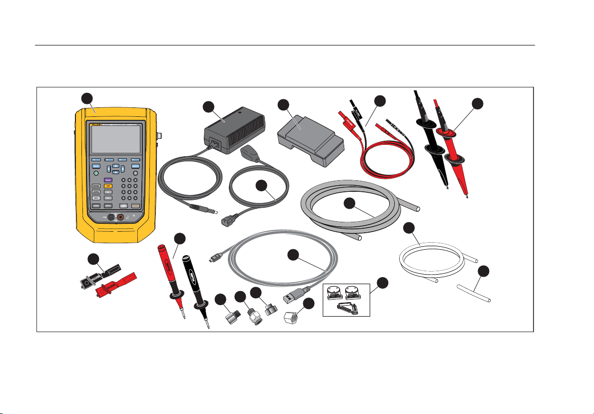
Standard Equipment
Figure 1 and Table 2 show standard equipment.
8
1
7
2
8
13
12
11
4
3
10
9
14
5
15
16
6
17
idj016.eps
Figure 1. Standard Equipment
Page 15
Automatic Pressure Calibrator
Standard Equipment
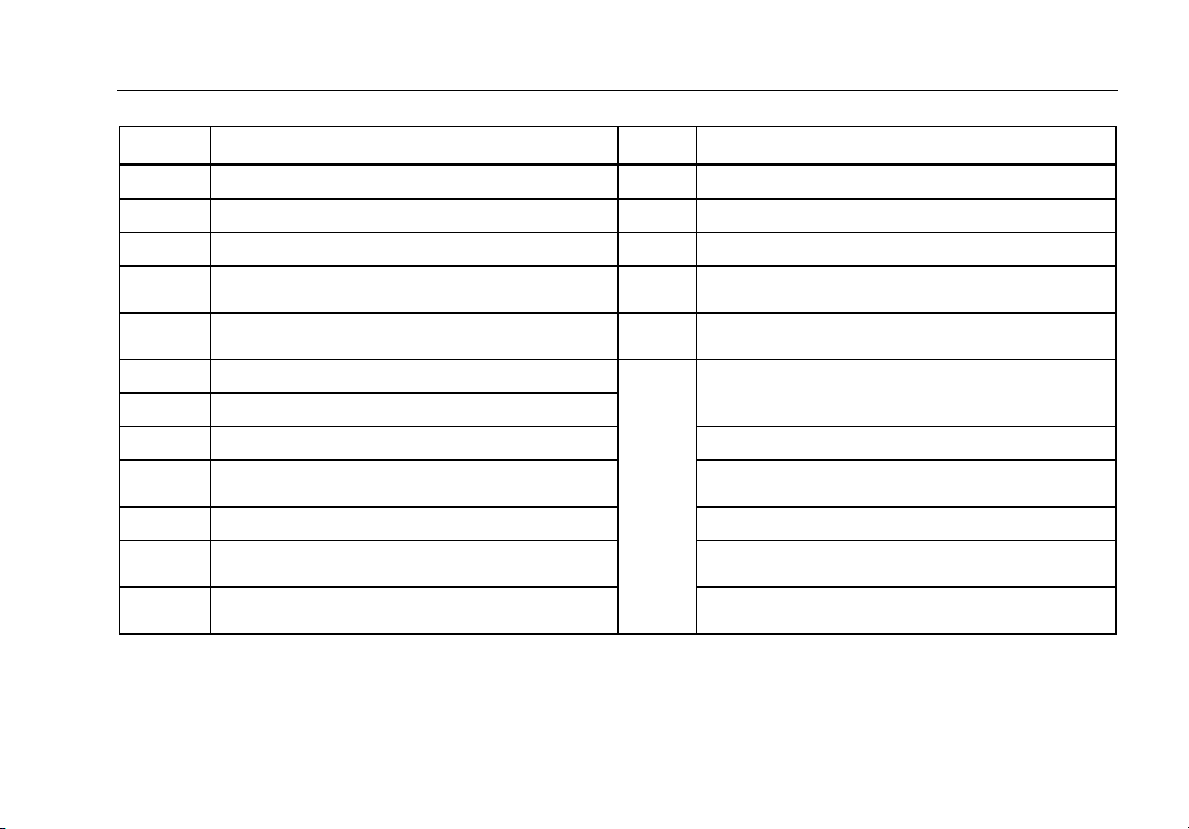
Table 2. Standard Equipment
No. Equipment No. Equipment
729 or 729 FC Automatic Pressure Calibrator
AC/DC converter
Mains line cable
Rechargeable Li-ion Battery
Stackable test lead set
AC280 Sure Grip hook set (red and black)
Alligator clips (red and black)
One set of TP220 test probes (red and black) Soft carrying case
USB communication cable: 3 ft (1 m) Type A
plug for host (PC) to Mini-B plug for device
Nylon hose 1/8 in diameter, 3.5 ft length Traceable calibration report with data
Fitting, 1/8 in NPT-Female x 1/4 in NPT-
Female
Tube fitting, male connector (qty 2), 1/8 in
NPT male connector, 1/8 in hose
Not
Shown
Fitting, 1/8 in NPT-Female X M20-Female
Fitting, 1/4 in BSP-Female X 1/8 in NPT-Female
Hanger Kit
Hose to drain condensed water generated from
the Product. 1/8 in diameter, 1 ft length
Hose for leakage test. 1/8 in diameter, 2 in
length
Adjustable quick-release strap for hanging the
Product
Printed multilingual Safety Information
PTFE Tape
International AC Adapter Kit
9
Page 16
729/729FC
Users Manual
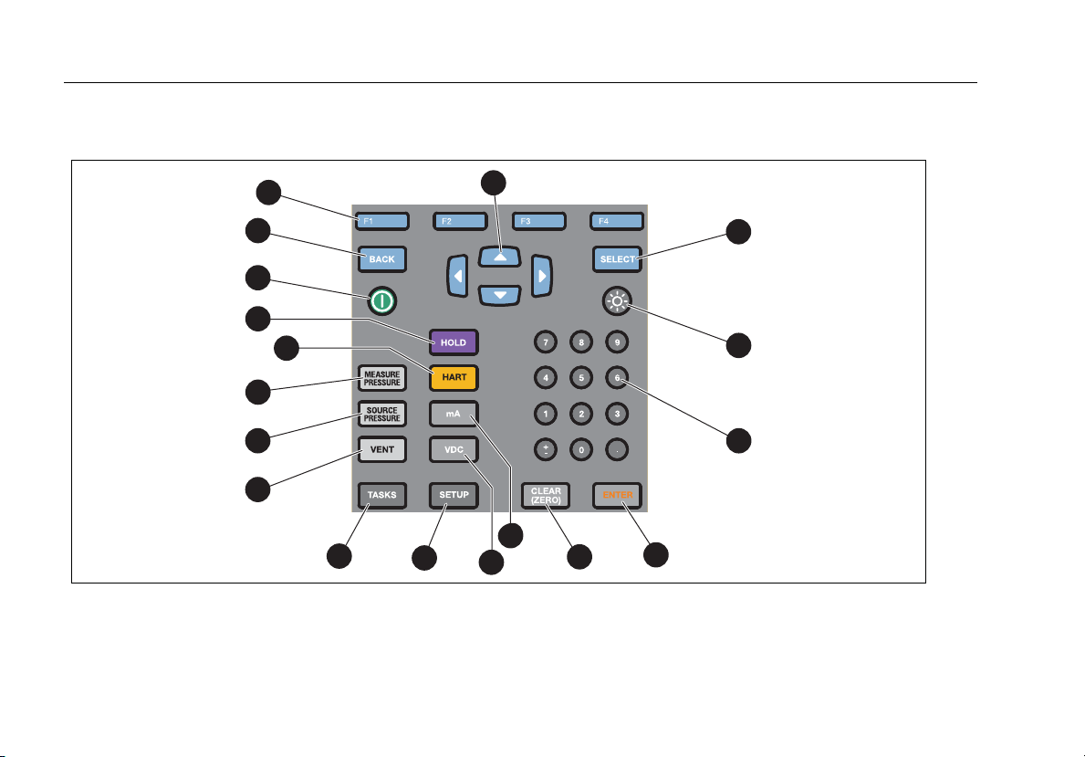
Buttons
See Figure 2 and Table 3 for the Product buttons and the softkeys.
10
18
16
15
14
3
2
1
17
13
12
4
10
11
Figure 2. Buttons
9
5
6
7
8
idj001.eps
Page 17

Automatic Pressure Calibrator
Buttons
Table 3. Buttons
Number Description Number Description
Power button. Push to turn on or turn off
the Product.
BACK button. Push to move to the
previous user interface (UI) screen. When
navigating through the screens, BACK can
move out of most screens and with
repeated pushes, can take you all the way
to the startup screen.
F1-F4 softkeys. Performs the specified
function of the label above each softkey on
the display. These labels change
throughout the UI.
Arrow buttons. Push to move the display
cursor left, right, up, or down. Cursor
highlights in yellow over the selection.
SELECT button. Push to make a selection
on the UI. This button cannot confirm
number or character choices (push
ENTER).
Display brightness button. Push to change the
display brightness from dim to bright and back again.
Numeric keypad. Used when a numeric entry is
necessary.
ENTER button. Push to make a selection on the UI.
Only ENTER confirms numbers and characters.
Confirm all editable items with ENTER.
CLEAR (ZERO) button. Push to clear highlighted
entry. When PI/PV/IP/SWT starts, push to zero the
pressure reading.
mA button. Push to select the mA measure function.
11
Page 18

729/729FC
Users Manual
fTable 3. Buttons (cont.)
Number Description Number Description
SOURCE PRESSURE button. Use this function
to output (source) a target pressure from the
Product. Use the arrows to select the Setpoint
field and enter the values with the number
buttons.
VDC button. Push to select the measure dc
voltage function.
12
SETUP button. Push to enter the Setup menu
to change operating parameters. See Setup
Menu.
TASKS button. Push to enter the Tasks menu.
See TASKS Menu.
VENT button. Push to release pressure at the
internal pressure port. VENTING shows on the
display as the Product vents. VENTED shows
after venting is complete.
MEASURE PRESSURE button. Use this function
for pressure measurement mode.
HART button. Push to enter HART
communication mode.
HOLD button. Push to freeze the reading on the
display. Push it a second time to release the hold
on the display. Push and hold to capture the
screen and save into memory.
Page 19
Automatic Pressure Calibrator
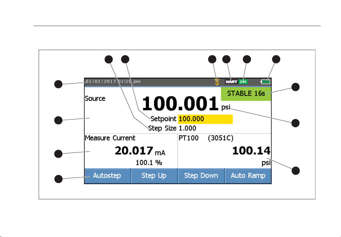
The Display
The Display
Figure 3 and Table 4 explain the display.
2 3 4 5 6
1
13
12
11
10
Figure 3. The Display
7
8
9
idj014.eps
13
Page 20

729/729FC
Users Manual
Table 4. The Display
Number Description Number Description
Step size indicator Pressure units indicator
External display shows selected device that is
connected. The device can be a pressure module,
Setpoint indicator
temperature probe, process variable (PV) of
connected HART device, or Fluke Connect
secondary device reading.
Fluke Connect on indicator (729 FC only) Softkey indicator
HART on indicator Current, voltage, or pressure switch display
24 volt loop power active indicator Main display with measured or sourced value
Battery charge level Time and date display
Pressure port status
14
Page 21
Automatic Pressure Calibrator
The Display
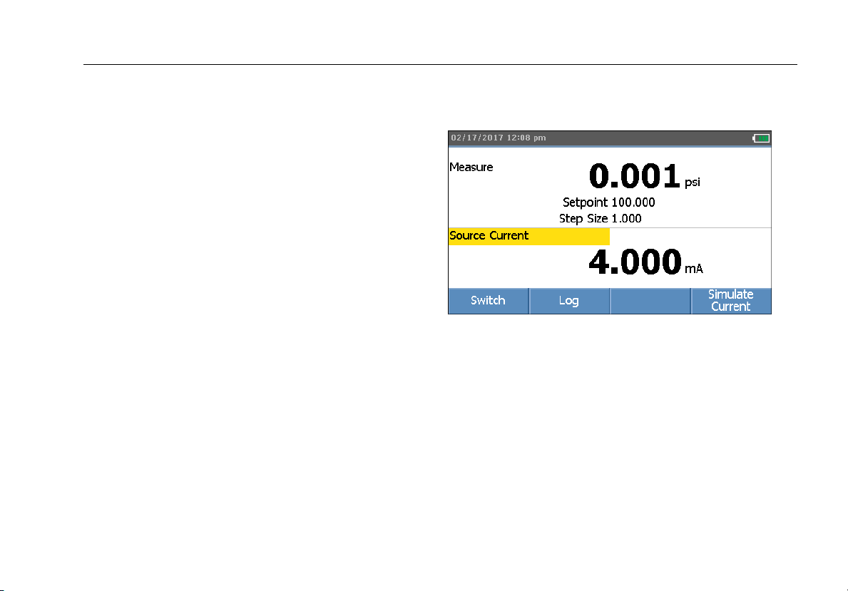
The display can also show different configurations:
Typically, the display does not show the third functions, see
Figure 4. See Triple-Function Display.
• The upper display for the internal pressure has these
different functions:
o VENT
o SOURCE
o MEASURE
• The lower display shows these different functions:
o Measure Current
o Source Current
o Simulate Current
o Measure VDC
o Switch
Figure 4. Typical Dual-Function Display
idj017.bmp
15
Page 22

729/729FC
Users Manual
The screen has two sections:
The upper display shows the internal pressure controller
status and includes:
• Mode: Measure, Source, and Vent
• Pressure Value: Current measured pressure and unit
• Status: Shows nothing in measure mode, NOT READY,
STABLE in source mode, and VENTING, VENTED in
vent mode.
• Setpoint: Current setpoint for source function.
• Step Size: The step size when (Step Up) and
(Step Down) are pushed when sourcing
pressure.
The lower display shows the electrical status and includes:
• Mode: Measure Current, Source Current, Simulate
Current, Measure V dc, and Switch.
• Reading: Current reading from measure functions or
setpoint for source functions.
• Switch State: Shows the pressure reading when the
switch contacts open and close.
• Percent: Shows the percentage value of 4 mA to 20 mA
or 1 V to 5 V in measure functions.
• Status: Shows Open circuit detected in mA source
mode.
16
Page 23
Automatic Pressure Calibrator
The Display
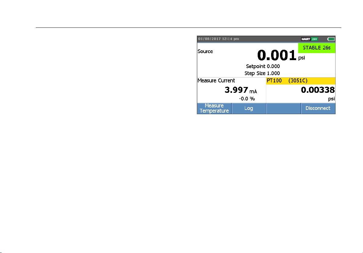
Triple-Function Display
When the third function (RTD, External Pressure Module,
HART Transmitter, or FC secondary device) is connected,
the Product changes to triple-function display automatically.
In the subsequent triple-function display, the original bottom
half of the display is divided into two parts:
• The left display continues to show the electrical
measurement display.
• The right display shows the model name, reading, and
units from the selected third function. See Figure 5. The
figure shows a transmitter device (3051C).
When more than one third function is available, use the
arrow keys to highlight the device (in yellow) in the right
display. Then use the softkeys to select the device to show.
Figure 5. Triple-Function Display
idj022.bmp
17
Page 24
729/729FC
Users Manual
RTD Connection
The display can show RTD temperature measurements in
the selected unit (C/F) as the third-function. When the
temperature unit field highlights, push the softkey to toggle
the temperature setting. The ohms reading shows.
Note
The Product supports PT100-385 RTD only.
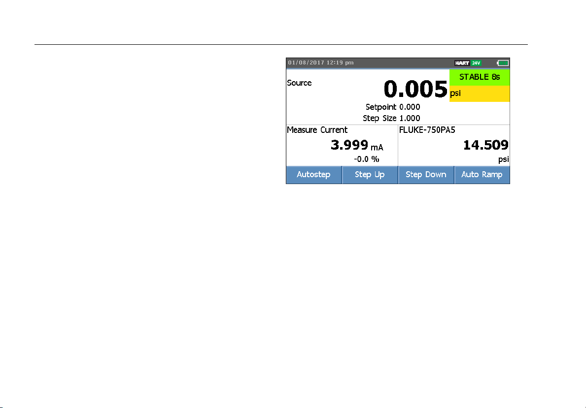
Pressure Module Connection
The Product automatically detects external pressure module
installation or removal. Move the cursor to the unit type and
push to configure the pressure-unit type (it can be
different from the pressure unit of internal pressure). Change
the unit type of the internal pressure to automatically change
the unit type of the pressure module.
Figure 6 shows a pressure module as the third function.
• When you plug in an external pressure module, the
pressure-unit type defaults to the internal pressure unit
type.
• When you remove or install an external pressure
module, the zero offset resets.
idj020.bmp
Figure 6. Triple-Function Display with External Pressure
Module Connected
18
Page 25

Automatic Pressure Calibrator
The Display
Fluke Connect Device Connection
The display shows connected FC device measurements as
the third-function.
See Setup Menu for information to manage secondary FC
devices.
19
Page 26
729/729FC
Users Manual
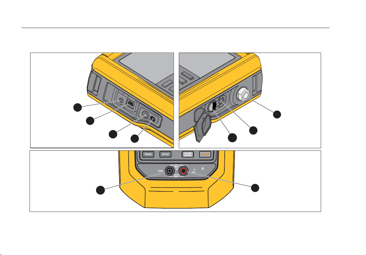
Ports
Figure 7 and Table 5 show the Product ports.
20
Left
Bottom
Right
1
7
2
3
8
4
Figure 7. Product Ports
5
6
9
idj013.eps
Page 27

Automatic Pressure Calibrator
Ports
Table 5. Product Ports
Number Description
Battery charger/universal power supply port. Use the battery charger for bench-top applications that have ac
line power available. Use the battery charger to charge the battery while installed in the Product.
USB port – Used for communication between the Product and a PC.
Push to drain condensation (see Maintenance Menu).
Drain port fitting connector.
External temperature port for RTD Temperature Probe
External pressure module port
Pressure connection
COM Port
Measure, source, and simulate mA; measure V dc and supply loop power.
21
Page 28
729/729FC
Users Manual
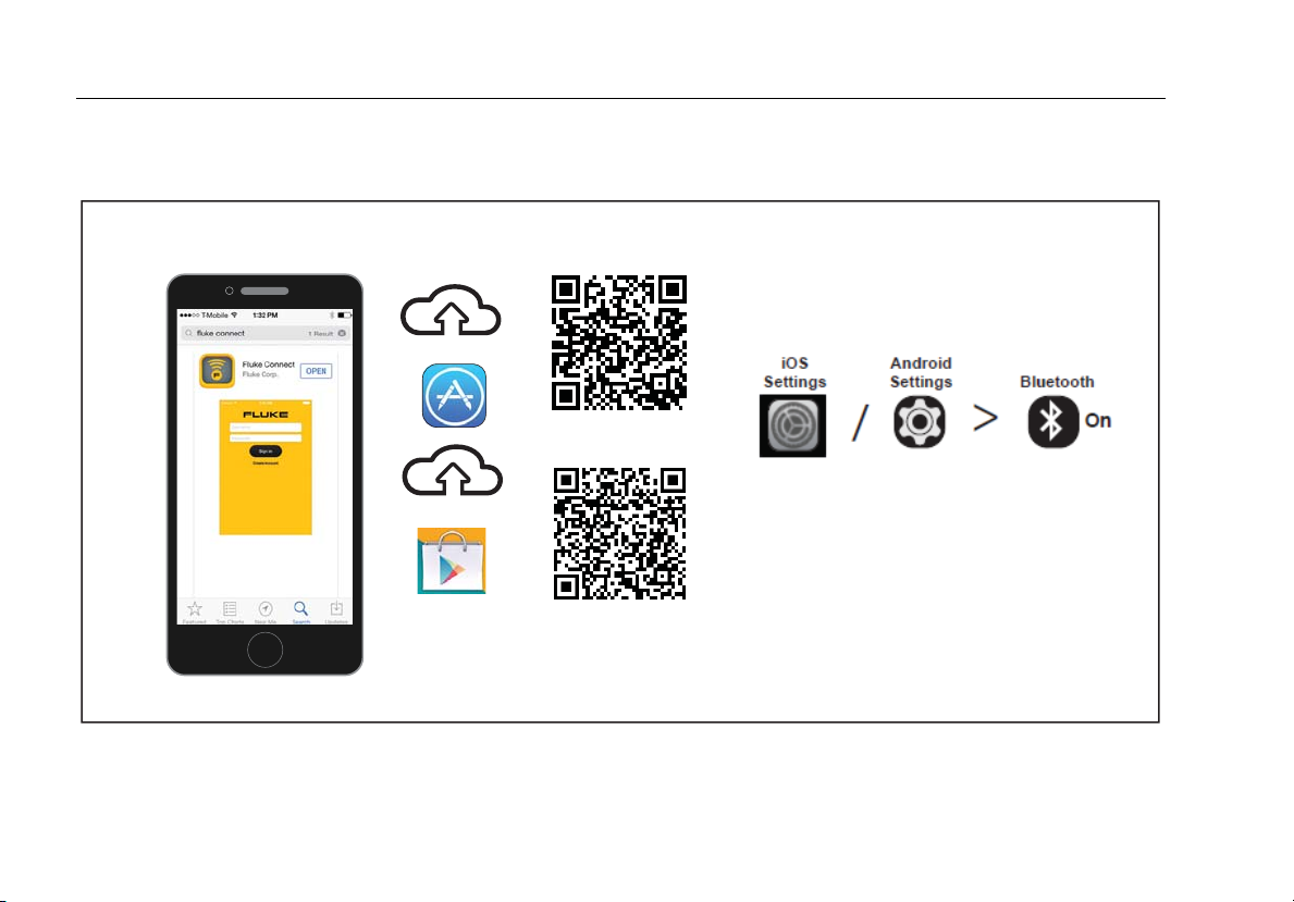
®
Download the Fluke Connect
To download the Fluke Connect® App, see Figure 8.
App
iOS
Android
22
Figure 8. Download the Fluke Connect App
idj025.eps
Page 29

Automatic Pressure Calibrator
Enable the Fluke Connect App
Enable the Fluke Connect® App
To enable the Fluke Connect App on your phone, see Figure 9.
1
Fluke Connect
2
®
Connect
3
4
idj027.eps
Figure 9. Enable the Fluke Connect App
23
Page 30

729/729FC
Users Manual
Setup Menu
Use the multi-page Setup menu to configure the Product
features.
Note
For some of the submenu functions, the Product
password is required. The default password is
1234.
To access the Setup menu, push .
The Setup menu includes submenus for Product
configuration. The submenus are:
1. 729 Information
2. 729 Setup
3. Manage Users
4. Manage Test Results
5. Manage Screen Shots
6. Manage Custom Tasks
7. Maintenance
Push the arrow buttons, , or to access these
submenus. Alternatively, push the corresponding number
button for access. Push to go to the previous menu.
To clear all stored files, push (Clear All Files).
Enter the Product password to use this function. This
action clears all stored test results, screen shots, and
custom tasks.
The subsequent sections explain the Setup menu and
submenus.
Manage FC Devices (729 FC Only)
1. Enter the Setup menu.
2. Push (Manage FC Device) to set 729 FC as
the primary device and discover other units that have
Fluke Connect. The connected product shows on the
display.
Push (Enable Fluke Connect) to set 729 FC as
the secondary device so it can be discovered by the
Fluke Connect App on smart phone.
Locator
When the Product shows several FC devices on the
Fluke Connect screen, highlight a product and push
(Locator). This causes the Fluke Connect button
on the listed product to flash repeatedly. The FC device
exits locator mode automatically or when
(Locator) is pushed again.
24
Page 31

Automatic Pressure Calibrator
Setup Menu
729 Information
The 729 Information submenu is an information-only
screen that shows information about the Product. The
screen shows:
• The Product model (729 or 729 FC)
• Serial Number
• Firmware Revision
• The last calibration date of the Product pressure
components.
• The last calibration date of the Product electrical
components.
There are also softkeys at the bottom of this screen.
These are:
• - Calibrate Pressure – Follow the prompts
on the screen and the Product takes you through a
procedure that calibrates the pressure components
of the Product. Enter the Product password to use
this function. (Options) lets you save the
calibration, go back a step, skip a step, or move to
the next section. See Calibration Manual for details.
• - Calibrate Electrical – Follow the prompts
on the screen and the Product takes you through a
procedure that calibrates the electrical components
of the Product. Enter the Product password to use
this function. (Options) lets you save the
calibration, go back a step, skip a step, or move to
the next section. See Calibration Manual for details.
• - Battery Information – An information-only
screen that shows if the battery is present, the
remaining battery charge level, battery temperature,
and battery voltage.
• - Change Password – Use to change the
password for advanced functions.
25
Page 32

729/729FC
Users Manual
729 Setup
The 729 Setup submenu shows the information in
Table 6.
Table 6. 729 Setup Menu
Menu Parameter Function
Push and use the arrows to
select the UI language: English,
Language
Date and Time
Chinese, French, German, Italian,
Portuguese, Spanish, Russian,
Japanese, or Korean.
Push and use the arrows to
access the Date and Time menu.
Once inside the menu, use the
arrows to select a parameter and
use the number keys to make
changes to these settings. For am or
pm, push . Once you make
changes, push (Done) to
store the new parameters. The
timestamp saves with any stored
results.
Table 6. 729 Setup Menu (cont.)
Menu Parameter Function
Set the format of the date. Use the
Date Format
Time Format
Number Format
Temperature Unit
[1]
softkeys to select yyyy-mm-dd,
mm/dd/yyyy, or dd/mm/yyyy.
Push the necessary softkey to select
12-hour or 24-hour time format. The
format changes in the Date Format
menu. or also changes
the format.
Push the necessary softkey to select
a decimal point or comma for the
numbering format. or also
changes the format.
Push the necessary softkey to select
between °C or °F. or also
changes the units.
26
Page 33

Automatic Pressure Calibrator
Setup Menu
Table 6. 729 Setup Menu (cont.)
Menu Parameter Function
The Product has a programmable
Auto Battery Timeout feature to
save the battery charge. Push the
arrow keys to highlight this line.
Push or to reach the
Auto Battery
Timeout
PCM Resolution
HART
Communication
Fluke Connect Enable/Disable
timeout menu. The choices are:
• Never
• 5 minutes
• 10 minutes
• 15 minutes
• 30 minutes
• 60 minutes
Choices are High and Low. High
resolution is the normal state, and
Low reduces the resolution one
digit.
Enable/Disable
Manage Users
The Manage Users submenu controls access to add or
delete Product user names from this menu.
To
• Add a new user: push (New):
Use the onscreen keyboard to add a new user.
Push the softkeys for Capslock ON (or OFF),
Backspace, and to complete the entry (Done).
1. Push the arrows to highlight each letter.
2. Push or to choose the letter.
3. When finished, push (Done) to
return to the Manage Users screen.
• Delete an existing user: push the arrows to
highlight a user and the push (Delete).
[1] Disabled in Japanese models.
27
Page 34

729/729FC
Users Manual
Manage Test Results
The Product saves test results as found and as left and
saves calibration results.
1. In the Setup menu, push the arrow buttons to
highlight Manage Test Results.
2. Push to show a list of tests. The tests are
designated by date and time, Tag ID, and serial
number.
3. Push the arrow buttons and or to view the
selected test results.
4. Push to select the As Found or As Left test
result.
5. Push to redo the calibration and save a new
test result.
To delete all test results:
1. Go to the Manage Test Results screen.
2. Push (Delete All).
3. Confirm to delete all records.
4. Push (OK) to delete all records or
(Cancel) to escape the deletion process.
Manage Screen Shots
The Product can take screen shots of any screen and
store them.
To take a screen shot:
1. Bring up the screen to save.
2. Push and hold . The Product shows File Saved.
To view the screen shots:
1. From the Setup menu, push the arrows to highlight
Manage Screen Shots.
2. Push or . The Product shows a list of
screenshots and their time and date stamps.
3. Use the arrows to highlight a screen shot.
4. Push or and the screen shot is shown. The
screen shows: You are reviewing a screen copy!
over the saved screen.
5. Push to delete the individual screen.
28
Page 35

Automatic Pressure Calibrator
Setup Menu
Manage Custom Tasks
Use this submenu to delete custom tasks (see Tasks
Menu). To delete a single task, use the arrow to select a
custom task and push (Delete). To delete all of
the tasks, push (Delete All).
Maintenance Menu
Maintenance has these sections:
• Drain Water (condensation)
• Keypad Test
• Pressure Sensor Characterize (see Calibration
Manual)
• Supply Sensor Self Calibration (see Calibration
Manual)
• Exhaust
Drain Water (Condensation)
To drain condensation from the Product, see Figure 10:
1. Connect the hose to collect drained water.
2. Push (Continue).
3. The display shows Creating pressure, please
standby. The pump works to establish a pressure.
4. To let the water out, use a small-tipped tool, such as
a small Philips screwdriver, to push the DRAIN
button on the side of the Product.
5. Push to repeat the drain operation.
6. When finished with water drain, push in on the fitting
to release the hose.
29
Page 36

729/729FC
Users Manual
30
Figure 10. Drain Water from Product
idj030.eps
Page 37

Automatic Pressure Calibrator
Tasks Menu
Keypad Test
Use this screen to check the Product buttons. Push any
button and verify the onscreen response.
For the power button, push and hold for 2 seconds.
Exhaust
The Exhaust function releases all pressure inside the
Product including the pressure reservoir. This reservoir
keeps the pressure stable and provides pressure if only
small pressure steps are necessary. Push for
Exhaust.
Tasks Menu
Tasks let you set up calibration and measurement tasks
to save and recall for later use.
To go to the Tasks menu, push . The Tasks menu
has these submenus:
• Pressure Transmitter (P/I)
• Pressure Switch (SW)
• Current to Pressure Test (I/P)
• Pressure Leak Test
• Pressure Transmitter (P/V)
• Pneumatic Pressure Transmitter (P/P)
Note
P/P tasks require a pressure module connected
to the Product.
31
Page 38

729/729FC
Users Manual
Pressure Transmitter (P/I)
Use this function to calibrate a P/I transmitter (pressure to
current) with current measurement. See Figure 11 for
connections:
1. From page 1 of the Tasks menu, push the arrows to
highlight Pressure Transmitter (P/I).
2. Push or .
3. From this screen, use the arrows, numeric keypad,
and to change the values of the Source
Pressure and Measure Current.
4. Push (PV Calibrate) if HART is enabled and
PV calibration is necessary.
5. Push to turn on (or off) 24 V loop power.
6. Once these values are specified, push
(Continue).
7. From this second screen, use the arrows, numeric
keypad, and to change the values of the
Tolerance of Range, Test Strategy, Auto Settling
Time, and Transfer Function.
8. Push to change the Transfer Function to
Square Root or Linear.
9. To select the Test Strategy, highlight the parameter
and push . Highlight the applicable listed test
strategy and push .
10. Push (Save as Customized) to store this
task for later use.
11. Once you enter the parameters, push
(Continue).
12. Push (Manual Test) or (Auto Test).
13. Push to adjust. Go to 0%, 50%, and 100%.
14. Push (As Left) to do the As Left test.
32
Page 39

Automatic Pressure Calibrator
Tasks Menu
Figure 11. Pressure Transmitter (P/I) Task Connections
idj005f.eps
33
Page 40

729/729FC
Users Manual
Pressure Switch (SW)
Use this feature to calibrate a pressure switch. See
Figure 12 for connections:
1. From page 1 of the Tasks menu, push the arrows to
highlight Pressure Switch (SW).
2. Push or .
3. From this screen, use the arrows, numeric keypad,
and to change the values of these parameters:
• Setpoint
• Tolerance
• Min Deadband
• Max Deadband
• Max Pressure
• Switch Type
Note
Make sure to push after EACH value
change.
You can save these settings as a customized task.
Push (Save as Customized). Recall this
customized task from the Tasks menu.
4. Once you enter the parameters, push
(Continue).
5. Push (Auto Test) or (Manual Test)
to do the As Found switch test. The test runs.
After the test runs, the results show on the display.
To save the test results:
1. Push (Done).
2. Push to edit the Tag information.
3. Push (Done).
4. Move the cursor to the S/N field (Serial Number).
5. Push to edit the S/N information.
6. Push (Done).
7. Move the cursor to the User ID field.
8. Push (User List) to select a user.
9. Push (Done).
10. Adjust the switch and push (Step Up)
and (Step Down) to verify.
11. Push (
As Left) to do the As Left test.
34
Page 41

Automatic Pressure Calibrator
Tasks Menu
Use low volume tubing
when possible
Pressure
Switch
idj008.eps
Figure 12. Switch Test Connections
35
Page 42

729/729FC
Users Manual
Current to Pressure Test (I/P)
Use this feature to calibrate a current to pressure (I/P)
converter with current source and pressure
measurements. See Figures 13 and 14:
1. From page 1 of the Tasks menu, push the arrows to
highlight Current to Pressure Test (I/P).
2. Push or .
3. From this screen, use the arrows, numeric keypad,
and to change the values of the source current
and measure pressure.
Note
Make sure to push after EACH value
change.
4. Once you enter the values, push (Continue).
Tolerance of Range, Test Strategy, and Auto Settling
Time can be set from here.
To save these settings as a customized task, push
(Save as Customized). You can then recall
the saved task from the Tasks menu.
5. Once you enter the parameters, push
(Continue).
6. Push (Manual Test) or (Auto Test).
7. Adjust with to go to 0%, 50%, and 100%.
8. Push (As Left) to do the As Left test.
36
Page 43

Automatic Pressure Calibrator
Tasks Menu
To compressed air source
I/P Transducer
Pressure
In
Out
Module
Figure 13. Current to Pressure Test (I/P) with External Pressure Module
idj009.eps
37
Page 44

729/729FC
Users Manual
To compressed air source
I/P Transducer
In
Out
38
Figure 14. Current to Pressure Test (I/P) with Internal Connections
idj009a.eps
Page 45

Automatic Pressure Calibrator
Tasks Menu
Pressure Leak Test
Use this feature to test a pressure device for leaks. For
connections, see Figure 15:
1. From this screen, use the arrows, numeric keypad, and
to change the values of these parameters:
• Setpoint (Pressure value)
• Settling Time
• Test Time
Make sure to push after EACH value change.
2. Push (Continue). When the pressure leak test
completes, the Product shows the results. Results
include Start Pressure, End pressure, Test time, and
Leak rate.
Note
39
Page 46

729/729FC
Users Manual
Pressure Transmitter (P/V)
Use this feature to calibrate a pressure to voltage
transmitter with voltage measurement. For connections, see
Figure 11.
1. From page 1 of the Tasks menu, push the arrows to
highlight Pressure Transmitter (P/V).
2. Push or .
3. From this screen, use the arrows, numeric keypad, and
to change the values of the source pressure and
measure voltage.
Push (Continue) to edit these other
parameters:
• Tolerance of Range
• Test Strategy
• Auto Settling Time
• Transfer Function (Linear or Square
Root).
Push (Save as Customized) to save these
settings as a customized task. Recall these customized
tasks from the Tasks menu at any time.
Pressure Transmitter (P/P)
To calibrate a pressure-to-pressure transmitter, use this
feature. This feature requires a pressure module to
measure pressure output from a connected transmitter.
To use the function, see Figure 15:
1. From page 1 of the Tasks menu, push the arrows
to highlight Pressure Transmitter (P/P).
2. Push or .
3. From this screen, use the arrows, numeric keypad,
and to change the values of the source
pressure and measure pressure.
4. Push (Continue) and these parameters
can be edited:
• Tolerance of Range
• Test Strategy
• Auto Settling Time
5. Push (Save as Customized) to save these
settings as a customized task. Recall this
customized task from the Tasks menu at any time.
40
Page 47

Automatic Pressure Calibrator
Tasks Menu
Pneumatic
Transmitter
In Out
+
+
Pressure
Module
idj026.eps
Figure 15. Pressure Transmitter (P/P) Connections
41
Page 48

729/729FC
Users Manual
HART Functionality
The Product interfaces with HART devices. It can:
• View and modify transmitter setup and data that
includes:
o Write Lower Range Value (LRV)
o Write Upper Range Value (URV)
o Write PV Unit
o Write Message and Descriptor
o Write Damping Value
o Write Date
• Perform service features including:
o PV Zero Trim
o mA Output Trim
o Trim to Applied Values
o Set Fixed mA Output
o Re-range Transmitter
o Device Diagnostics
• Perform HART calibration without using a Task (Ad
hoc)
• Perform HART calibration from a downloaded Task
42
Page 49

Automatic Pressure Calibrator
HART Functionality
Push and the Product searches (polls) the bus to find
any connected HART devices. From this screen, there are
these softkeys:
- Communicator Only
- Loop Power +24V ON
- Enable HART 250Ω
- Restart BUS Polling
Once Polling finds the transmitter(s), move the cursor to the
desired tag number and select (Continue) to select.
Loop Power +24V ON
The Product supplies loop power at 24 V dc to a current
transmitter disconnected from the system. To supply 24 V
loop power:
1. From the HART menu, push (Loop Power
+24V ON). The Product polls the bus to see if a
transmitter is connected.
2. With the transmitter disconnected from normal loop
power, connect the Product test leads in series with the
instrument current loop as shown in Figure 16.
3. The mA display shows measure loop current.
43
Page 50

729/729FC
Users Manual
TEST DC PWR
+–+–
–+
44
Figure 16. Connection with Loop Power Enabled
idj029.eps
Page 51

Automatic Pressure Calibrator
HART Menu
Enable HART 250Ω
The Product has a selectable 250 Ω HART resistor to
facilitate use with HART devices. Enable the HART resistor
when you connect the Product to a HART device. The
HART resistor defaults to OFF.
To turn on or off the HART resistor, push (Enable
HART 250Ω) or (Disable HART 250Ω).
HART Menu
The HART menu has these functions that configure and
calibrate a HART device:
• HART Data
• HART Service
• Calibrate (Ad Hoc)
• Find Task by Tag
• Bus Polling
From the HART menu, push (Disconnect) to
disconnect from HART communication, or push
(Continue) to continue to the highlighted entry.
HART Data
The HART data screen shows information about the
connected HART device. Push (Page Up) or
(Page Down) where necessary.
You can modify certain fields that include:
• Tag ID
• PV Unit Type
• Lower Range Value (LRV)
• Upper Range Value (URV)
• Damping
• Message
• Descriptor
• Date
45
Page 52

729/729FC
Users Manual
HART Service
HART Service includes these submenus:
• PV Zero Trim
• mA Output Trim
• Trim to Applied Values
• Set Fixed mA Output
• Re-range Transmitter
• Device Diagnostics
Highlight the HART Service menu selection and push
(Continue). When you enter some of the
submenus, a warning tells you to remove the loop from
AUTOMATIC control. Push (Continue).
PV Zero Trim
This function sets the digital pressure value of the
transmitter to zero.
1. Push (Trim Zero) to trim the PV output value to
zero.
2. Push (Done) when completed.
mA Output Trim
In the mA output trim screen, you can adjust the transmitter
output.
1. Start with the 4 mA range. Push (Fetch) to get
the current measured mA value.
2. Push (Trim 4 mA) to send the measured value
for correction. Push (Next Point). The Product
moves to the 20 mA range.
3. Repeat steps 1 and 2.
4. When complete, push to return to the previous
point or (Done).
Trim to Applied Values
1. Enter the LRV pressure value necessary in the Setpoint
entry and then push and let the pressure settle.
2. Push (Trim LRV) to trim the lower range of
pressure applied.
3. Enter the necessary URV pressure value in the
Setpoint entry and push and let the pressure
settle.
4. Push (Trim URV) to trim the upper range of
pressure applied.
46
Page 53

Automatic Pressure Calibrator
HART Menu
Set Fixed mA Output
Enter the necessary mA value to output from the connected
transmitter.
• Push (Step Up 4mA) to increase mA output in
4 mA steps.
• Push (Step Down 4mA) to decrease mA output
in 4 mA steps.
Re-range Transmitter
Change the Upper Range Value (URV) and the Lower
Range Value (LRV) of the connected transmitter from this
screen.
1. Enter the Upper Range Value (PV URV) necessary.
2. Push to select.
3. Push (Send) to change the URV.
4. Enter the Lower Range Value (PV LRV) necessary.
5. Push to select.
6. Push (Send) to change the LRV.
Device Diagnostics
Select Device Diagnostics to send the self-diagnostics
command to the connected transmitter and view the
transmitter Self Test result.
Calibrate (Ad hoc)
Calibrate (Ad Hoc) calibrates a connected HART device
without a downloaded task.
The opening screen shows the task type and
source/measure configuration for the device. The
transmitter HART configuration is copied into this
configuration screen. Correct as needed for your test.
1. Push (PV Calibrate) to change the measure
from mA to the PV source value of the transmitter.
2. Push (Disable/Enable Loop Power).
3. Push (Continue) to continue to second
configuration screen. These choices are shown:
• Tolerance of Range
• Test Strategy
• Auto Settling Time
• Transfer Function
47
Page 54

729/729FC
Users Manual
These softkeys are active:
– Linear/Square Root Selection
– Save as Customized
– Leak Test
– Continue
The next screen starts the As Found Calibration. These
softkeys are active:
– Abort
– Manual Test
– Auto Test
Test results show after all strategy points have recorded the
measurements. Measurements in specification show as
black. Measurements out of specification show as red.
1. Push (Done) or (Abort).
2. Enter the Tag ID, serial number of the device, and the
User ID.
3. Push (Done)
Adjust
Push (HART Adjust). These choices are shown:
• PV Zero Trim
• mA Output Trim
• Trim to Applied Values
PV Zero Trim
To set the digital pressure value of the Product to zero:
1. Push (Trim Zero).
2. Push (Done).
mA Output Trim
From the mA output trim screen, you can fetch the current
PV value and send this value to the transmitter to adjust the
PV to the correct mA output.
1. Starting with the 4 mA range, push (Fetch) to
get the current measured mA value.
2. Push (Trim 4mA) to send the measured value
for correction.
3. Push (Next Point). The Product moves to the
20 mA range.
4. Repeat steps 1, 2, and 3.
5. When complete, push to return to the previous
point or (Done).
48
Page 55

Automatic Pressure Calibrator
Measure Mode
Trim to Applied Values
1. Enter the LRV pressure value necessary in the Setpoint
entry and let the pressure settle.
2. Push (Trim LRV) to trim to the lower range of
pressure applied.
3. Enter the URV pressure value necessary in the
Setpoint entry and let the pressure settle.
4. Push (Trim URV) to trim to the upper range of
pressure applied.
As Left
Push (As Left). Repeat the procedure from As
Found.
Calibration results save to the Test Results menu.
Find Task by Tag
Downloaded tasks from DPCTrack2 or other supported
software are shown. Use the up and down arrows to scroll
through the tasks. Push (Page Up) or
(Page Down) where necessary. Push (Recall) to
recall the highlighted task.
Bus Polling
Bus Polling goes back into the bus polling screen and scans
for connected HART devices.
If no HART device is found after Polling has completed,
push (Restart Bus Polling) to restart bus polling to
search of the Product BUS for HART devices. The Product
locates the device.
Measure Mode
The measure mode has these functions:
• mA dc measure
• mA dc source
• mA dc simulate
• V dc measure
• Switch (continuity)
The lower left of the display shows the operation mode.
49
Page 56

729/729FC
Users Manual
Current Measurement
The Product measures 0 mA to 24 mA.
Move the cursor to highlight Measure Current. Push
to Source Current. Push to Simulate
Current.
+–
Figure 17. VDC Measurement Connections
Volts Measurement
The Product measures 0 V dc to 30 V dc. Figure 17 shows
measurement connections for voltage measurements.
idj004f.eps
50
Page 57

Automatic Pressure Calibrator
Measure Mode
Pressure Measurement
The Product supports the 700P and 750P series pressure
modules. See Accessories. Before you use a pressure
module, read its instruction sheet. The modules are different
in how they are used, zeroed, what types of process
pressure media are allowed, and accuracy specifications.
Figure 18 shows gage and differential modules. Differential
modules also operate in gage mode when you leave the low
fitting open to atmosphere.
To measure pressure, attach the applicable pressure
module for the process pressure you will test as described
in the module’s instruction sheet.
To measure pressure:
Warning
To prevent personal injury, shut off the valve
and slowly bleed off the pressure before
attaching the pressure module to the pressure
line to avoid a violent release of pressure in a
pressurized system.
Low
Differential
R
ANGE
700
P
RESS
P
0
4
U
R
E
15 P
MO
1
DULE
0
0
k
SID/G
P
a
1
b
a
r
High
RA
Gage
7
N
0
P
0
GE
R
P
E
06
S
SU
RE
10
MO
7
DU
0
00 k
PSIG
LE
P
a
7
b
a
r
hhb001.eps
Figure 18. Gage and Differential Pressure Modules
51
Page 58

729/729FC
Users Manual
Caution
To prevent possible damage to the Product or
to equipment under test:
• Never apply more than 10 lb-ft. of torque
between the pressure module fittings, or
between the fittings and the body of the
module.
• Always apply correct torque between the
pressure module fitting and connecting
fittings or adapters.
• Never apply pressure above the rated
maximum printed on the pressure module.
• Use the pressure module only with
specified materials. See the printing on the
pressure module or the pressure module
instruction sheet for the acceptable
material compatibility.
Connect a pressure module to the Product as shown in
Figure 19. The pressure module shows on the display after
several seconds once installed.
The Product automatically senses the pressure module
attached and sets its range accordingly.
Note
Before doing a task that sources or measures
pressure, zero the Product.
1. With the pressure module highlighted in the third
screen, push (Zero External) to zero the
pressure. When zeroing absolute pressure modules,
enter the current barometric pressure when the
displayed value turns to yellow highlight
2. Zero the pressure. See the module’s Instruction Sheet.
Modules can have different zeroing procedures that
depend on module type.
52
Page 59

Automatic Pressure Calibrator
Measure Mode
Isolation
Valve
Gage
Module
Differential
Module
HL
Tank
Figure 19. Pressure Module Connections
Idj010..eps
53
Page 60

729/729FC
Users Manual
Autostep and Auto Ramp the Output Value
Autostep and Auto Ramp can automatically adjust the value
of source functions for pressure or current.
Autostep
To configure the Product to make a sequence of steps that
run automatically:
1. Connect the Product to the test circuit.
2. From the main screen, push (Autostep).
3. Set the Product for the necessary source function:
• (Pressure)
• (Current)
4. From this screen, use the arrows, numeric keypad, and
to change the values of Start and End Values, and
Number of Steps and time per step.
5. Select the Repeat Mode:
• (One Time)
• (Repetitive)
6. Select the Step Style:
• (Sawtooth)
• (Triangle)
7. Push (Start).
8. The Product automatically starts the step function. The
softkey label changes to Stop Step.
9. To Push the Stop Step softkey to stop the automatic
step function.
10. Push the Done softkey to continue normal operation.
54
Page 61

Automatic Pressure Calibrator
Measure Mode
Auto Ramp the Output
When ramped, the source sweeps up or down in value. Use
the Auto Ramp feature to verify a switch or alarm, or when a
smooth increase or decrease of the output function is
necessary. Set the Product to ramp up Pressure or Current.
1. From the main screen, push (Auto Ramp).
2. Set the Product for the necessary source function:
• (Pressure)
• (Current)
3. Use the arrows, numeric keypad, and to change
the Start Values, End Values, and Slew Rate (Ramp
Time).
4. Select the Repeat Mode:
• (One Time)
• (Repetitive)
5. Select the Step Style:
• (Sawtooth)
• (Triangle)
6. Push (Start).
While the signal ramps, the output adjusts to the value. The
selection of endpoints and ramp time determines the size of
steps. For example, if you set the Product to ramp from
1 mV to 1 V over 10 seconds, the output adjusts in
approximately 25 mV steps. The Ramp function continues
until you get the selected limit.
55
Page 62

729/729FC
Users Manual
Temperature Measurement
To measure temperature with an RTD probe accessory,
connect the probe into the RTD port on the right of the
Product. Make sure the correct probe type is used. Use
Fluke-720RTD, PN 4366669 or the Fluke-720URTDA, PN
4382695.
The standard probe has a 10-inch insertion depth with a ¼-
inch diameter stainless steel sheath. See Figure 20.
Note
The factory default type is PT100-385 so if the
Product is used with the Fluke 720 RTD Probe (PN
4366669), it is not necessary to set the probe type.
Connect the probe to the Product and configure
the display to read temperature.
The display shows “OL” when the measured
temperature is outside the nominal measurement
range of the RTD function (below -40 °C or above
150 °C).
RTD Probe
Figure 20. Temperature Probe Connection
idj015.eps
56
Page 63

Automatic Pressure Calibrator
Measure Mode
Source mA Mode
The operation mode (for example, measure or source)
shows on the display. If the Product is not in mA source
mode, push .
To source mA:
1. Connect the test leads as necessary.
2. Key in the necessary output value (for example, to
source 5.5 mA, push ).
3. Push .
4. To change the output value, record a new value and
then push .
4. To set the output value in the present source function,
push then enter the desired value and push .
5. To turn off sourcing completely, select another function.
Note
Use the source current function to drive a current
input device. This is different from the loop power
function in which the Product is powering a
process instrument.
4 to 20 mA Simulation
To configure the Product as a load on a current loop:
1. Move the cursor to the analog function indicator and
push (Simulate Current).
2. Enter the necessary value.
3. Connect an external loop supply to the mA port as
shown in Figure 21.
57
Page 64

729/729FC
Users Manual
58
Loop
Power
Supply
+
+24
–
Figure 21. Connections to Simulate a 4 to 20 mA Transmitter
UUT
idj011.eps
Page 65

Automatic Pressure Calibrator
Log
Log
Users can record a series of pressure or mA
measurements for later upload to a host computer. The
Product records a maximum of 8000 readings, depending
on the reading rate, duration, and how much memory is in
use for other functions such as tasks or stored results.
Record the reading rate and duration in minutes.
To log data:
1. From the main screen, push (Log). Adjust
the Reading Rate and Duration with the arrow
buttons and then push to select parameters
from the Log screen.
2. Choose the Log Source from any of the available
measured values with , , or .
The log source can be internal pressure, external
pressure, mA, V dc, HART PV, or temperature.
3. For Reading Rate: push to adjust the reading
rate from 1 /m to 60 /m.
4. For Duration: use the numeric keypad to record the
duration in minutes, followed by . The maximum
depends on the reading rate and how much memory
is available to log data.
5. Push (Start) to begin. The Product logs the
measured values of the selected source for the preselected duration. Push (Abort) to stop
logging.
Results show after the Product logs the data. Push
(Abort) or (Done). If you push
(Done), enter Tag, S/N, and a User ID. The Product
saves the results and are recalled under the
Setup>Manage Test Results menu. Upload the logged
Product data to DPCTrack2 for review in a graphical
report.
Communication with a PC
Download procedures from a PC to the Product and
upload test results to a PC from the Product. A PC,
Microsoft Windows, USB cable (supplied), and Fluke
DPCTrack2
partner’s software are required. See the DPCTrack2
Users Manual for further instructions. See Figure 22 for
the connection.
Download DPCTrack2 Trial Version Software and the
DPCTrack2 Users Manual from
www.fluke.com/productinfo .
application software, or a qualified Fluke
59
Page 66

729/729FC
Users Manual
USB Port
60
Figure 22. Connection to a PC
idj006f.eps
Page 67

Automatic Pressure Calibrator
The Battery
The Battery
The Product features a rechargeable battery. Charge the
battery while it is inside or outside of the Product. This
allows you to have more than one fully charged battery on
hand.
Charge the Battery
Before the Product is used, charge the battery. To charge
the battery while in the Product, connect the battery
charger to the Product.
The battery fully charges in 8 hours.
To charge the battery outside of the Product, see
Figure 24 for battery access:
1. Place the Product face down.
2. Lift the Product stand to expose all screws.
3. Remove the six screws with a Phillips screwdriver.
4. Pull off the back.
5. Remove the battery.
6. Connect the battery charge to the input on the
battery.
The battery charge indicator (top-right of display) shows
while the battery is outside of the Product. Solid green
bars show the level of charge on the battery. When all
bars are illuminated and solid, the battery is fully charged.
The bars progressively illuminate to show that the battery
is currently charging.
Battery Life
The battery charge indicator shows on the upper right of
the display.
Table 7 shows the typical operation time for a new, fully
charged battery. Product performance meets its
specification until the battery charge indicator reads
empty.
Table 7. Typical Battery Life
Operation Modes Battery Life
Measure, continuous 20 Hours
Measure and source,
with loop power on,
continuous
Typical intermittent
operation
10 Hours
>16 Hours
61
Page 68

729/729FC
Users Manual
Maintenance
Warning
To prevent possible electrical shock, fire, or
personal injury:
• Have an approved technician repair the
Product.
• Do not operate the Product with covers
removed or the case open. Hazardous
voltage exposure is possible.
• Remove the input signals before you
clean the Product.
• Use only specified replacement parts.
• Run “Exhaust” before you open the battery
door.
Clean the Product
Clean the Product and pressure modules with a soft cloth
dampened with water or water and mild detergent.
Caution
To prevent possible damage to the Product,
do not use solvents or abrasive cleansers.
Clean the Pump Valve
1. Remove the battery door (see Battery Replacement)
and locate the pump valve caps, see Figure 23 ().
2. Use a small screwdriver to remove the two valve
retention caps located in the oval shaped opening on
the underside of the Product.
3. Gently remove the spring and O-ring assembly.
4. Set aside the valve assemblies and clean out the
valve body with a cotton swab soaked in isopropyl
alcohol (IPA).
5. Repeat this process several times with a new cotton
swab until there is no sign of residue.
6. Run the pump for a few seconds.
7. Clean the O-ring assembly and O-ring on the
retention caps with IPA and inspect the O-rings
closely for any cuts, nicks, or wear. Replace if
necessary.
62
Page 69

Automatic Pressure Calibrator
Maintenance
8. Inspect the springs for wear or loss of tension. They
should be approximately 3.8 mm (0.15 in) long in the
relaxed state. If they are shorter, the O-ring will not
seat properly. Replace if necessary.
9. Clean and inspect all parts and then reinstall the Oring and spring assemblies into the valve body.
10. Reinstall the retention caps and gently tighten the
cap.
11. Seal the output of the Product and pump up the unit
to at least 50 % of its rated pressure.
12. Release the pressure and repeat several times to
ensure that the O-rings seat properly.
The Product is now ready for use.
1
idj031.eps
Figure 23. Pump Valve
63
Page 70

729/729FC
Users Manual
In Case of Difficulty
Warning
To prevent possible electrical shock, fire, or
personal injury, do not use the Product if it
operates abnormally. Protection may be
impaired. When in doubt, have the Product
serviced.
If the Product does not turn on, check the battery charge.
Disconnect the battery charger. If the Product receives
power, the power button is illuminated. If the button is
illuminated, but the Product does not turn on, have the
Product serviced. See Contact Fluke.
64
Page 71

Automatic Pressure Calibrator
Maintenance
Battery Replacement
Replace the battery when it no longer holds a charge for
the rated interval. The battery normally lasts for up to 300
charge/discharge cycles. To order a replacement battery,
see Contact Fluke and User-Replaceable Parts.
Note
Take spent batteries to a qualified recycler or
hazardous materials handler for disposal.
Contact an authorized Fluke Service Center for
recycling information.
To replace the battery, see Figure 24:
1. Push and select Maintenance.
2. Push (Exhaust) to release Product internal
pressure.
3. Turn the Product Off.
4. Remove test leads.
5. Make sure the Product is unplugged from its charger.
6. Turn the Product over.
7. Lift up the bail and remove the six screws with a
Phillips screwdriver.
8. Lift off the back battery cover.
9. Replace the battery.
10. Replace the back cover and screws.
Figure 24. Replace the Battery
idj007.eps
65
Page 72

729/729FC
Users Manual
Update Product Firmware
To update the Product firmware version:
1. Turn on the Product.
2. Connect the USB cable (provided) to a PC (see
Figure 23).
3. Go to www.fluke.com/productinfo.
4. Click on “Find your software”.
5. Search for “729”.
6. On the results page, select the Software
Downloads tab.
7. Click on the necessary software link.
8. Read the instructions on this page.
9. Download the Firmware file.
10. Click on the Firmware exe file.
Calibration Data
The date of the last calibration and verification shows on
the sticker on the calibration certificate and on the
Instrument Information screen in screen in the Setup
menu. The CAL. STATUS number on the sticker should
always match the Calibration Status number in the
calibration screen. Only qualified personnel should
calibrate the Product.
Service Center Calibration or Repair
Only qualified service personnel must do calibration,
repairs, or service not included in this manual. If the
Product fails, examine the battery pack first, and replace
it if necessary.
Make sure to operate the Product in accordance with the
instructions in this manual. If the Product is faulty, send a
description of the failure with the Product. Pressure
modules do not need to accompany the Product unless
the module is faulty also. Be sure to pack the Product
securely, in the original shipping container if it is
available. See Contact Fluke and the Warranty
Statement.
66
Page 73

Automatic Pressure Calibrator
Maintenance
Error Messages
The Product display shows error messages when the
Product fails to meet certain conditions or there is a
Table 8. Error Messages
Error Message Explanation Potential Root Cause and Solution
Too many errors Too many errors, the error queue overflow.
Cannot read file Failed to read file from file system.
Cannot recall procedure Failed to recall downloaded procedure.
Cannot store results Failed to store task results.
problem with the configuration of the Product or test. See
Table 8 to troubleshoot these issue.
Clear the errors with the Product user
interface
1. File corrupted, delete the file and try
again.
2. Data flash memory failure, the main
PCA needs service.
1. The downloaded procedure contains an
illegal configuration.
2. File corrupted, download the procedure
again.
1. Not enough space, delete some files
and run the task again.
2. Delete all results and run the task again.
67
Page 74

729/729FC
Users Manual
Error Message Explanation Potential Root Cause
Table 8. Error Messages (cont.)
Filesystem fatal error
Cannot save screen Failed to save screen into filesystem.
Calibration error when
(name of step)
HART command failed (command
dependent explanation)
Lost connection to PCM The link to the PCM is broken.
Lost connection to EMM The link to EMM is broken.
PCM temperature too high
Failed to load filesystem from flash memory
when startup.
Calibration failed at current step.
Error returned from HART device of previous
command.
The temperature of PCM reaches its high
limit.
68
Data flash memory failure, the main PCA
needs service.
Not enough space, delete some files and
try again.
Make sure connection and reference are
correct and try again.
Device-dependent error, please refer to
user manual of HART transmitter.
Cycle power, if error persists, the unit
needs service.
In measure mode, let the PCM cool down
and try the task again.
Page 75

Automatic Pressure Calibrator
Maintenance
Table 8. Error Messages (cont.)
Error Message Explanation Potential Root Cause
PCM pressure exceeds limit The pressure of PCM exceeds its limit. Vent pressure and do the task again.
Failed to initial DPC memory
Invalid Instrument Setup,
Default loaded
Zero offset too large, please
vent
Flash memory error Failed to initial data flash memory.
Lost connection to external
pressure module, Task
aborted
Failed to initial memory lists for
documenting.
Checksum of instrument setup failed. All
settings reset to their default values.
Pressure is higher than limit for zeroing. Vent pressure and zero the Product again.
Running task aborted, due to lost connection
to external pressure module.
1. Clear all files and try again.
2. Data flash memory failure, the main
PCA needs service.
Cycle power, if error persists, the main PCA
needs service.
1. Make sure the external pressure module
is connected, and run the task again.
2. Replace the external pressure module.
If still undetected, the Product needs
service.
69
Page 76

729/729FC
Users Manual
Error Message Explanation Potential Root Cause
Table 8. Error Messages (cont.)
Lost connection to HART
transmitter, Task aborted
Lost connection to FC devices,
Task aborted
Lost connection to RTD, Task
aborted
Open circuit detected Open circuit detected while sourcing mA. Connect the circuit properly and try again.
Invalid Task Setting Task setting contains invalid items.
Running task aborted, due to lost connection
to HART transmitter.
Running task aborted, due to lost connection
to Fluke Connect secondary unit.
Running task aborted because RTD was
removed.
Make sure the transmitter is connected and
powered. Try HART polling again. After
connected, rerun the task.
Turn on the FC secondary device and make
sure FC is active. Redo the discovery
process. After connected, run the task
again.
Make sure the RTD probe is connected and
run the task again.
Verify zero/full-scale value defined in the
task are in the range of the selected
pressure source and try again.
70
Page 77

Automatic Pressure Calibrator
Maintenance
Table 8. Error Messages (cont.)
Error Message Explanation Potential Root Cause
Input Out Of Range Invalid input signal when calibrating.
Invalid EMM/PCM CAL
constant, Factory value
loaded
Invalid EMM/PCM CAL
constant, Default value
loaded
Checksum failed for calibration constant,
factory values are loaded.
Checksum failed for factory calibration
constant, default values are loaded.
Make sure input signal is in the range of
the current calibration point, and try again.
The unit needs service for recalibration.
The unit needs service for recalibration.
71
Page 78

729/729FC
Users Manual
Table 8. Error Messages (cont.)
Error Message Explanation Potential Root Cause
1. The pressure volume is too large,
reduce the volume and try again.
2. The leakage of pressure volume is too
Supply Pressure Too Low
Value out of range Value input is out of range. Try to configure a valid value.
Failed to create supply pressure for the
current setpoint.
large. Test the leakage and try again.
3. Ambient pressure is lower than the
negative gauge setpoint. Change the
negative gauge setpoint to a reasonable
value at current ambient pressure.
4. The unit needs service.
Function not available
Illegal Operation Illegal operation for the current state.
Selected function is not available for the
current state.
72
Page 79

Automatic Pressure Calibrator
Maintenance
HART Commands
See Table 9 for Product HART commands.
Number Command Description Type
Table 9. Supported HART Commands
Number
1 Read Primary Variable Universal
2
3
8
12 Read Message Universal
13 Read Tag, Descriptor, Date Universal
14
15 Read Device Information Universal
17 Write Message Universal
18 Write Tag, Descriptor, Date Universal
Command Description
Read Loop Current and Percent
of Range
Read Dynamic Range and Loop
Current
Read Dynamic Variable
Classification
Read Primary Variable
Transducer Information
Type
Universal
Universal
Universal
Universal
20 Read Long Tag Universal
21 Read Unique Identifier Universal
35
40 Enter/Exit Fixed Current Mode
41 Perform Self Test
43 Set Primary Variable Zero
44 Write Primary Variable Units
45 Trim Loop Current Zero
46 Trim Loop Current Gain
48 Read Additional Device Status
Write Primary Variable Range
Value
Common
Practice
Common
Practice
Common
Practice
Common
Practice
Common
Practice
Common
Practice
Common
Practice
Common
Practice
73
Page 80

729/729FC
Users Manual
Documenting Functionality
The Product uses calibration management software to
communicate with documenting software. The Product
documents As Found, As Left, and single-reading results.
Download tasks by pre-defined tag numbers and save the
results to Product memory. Review or delete these results
when necessary.
Strap
Attach the Product carrying strap as shown in Figure 25.
Adjust the straps as necessary to hang the Product on
any sturdy support.
74
Page 81

Automatic Pressure Calibrator
idj012.eps
Figure 25. Product Strap
75
Page 82

729/729FC
Users Manual
Hanger Accessory
Figure 26 shows the provided magnetic hanger
accessory.
76
Figure 26. Hanger Accessory
idj018.eps
Page 83

Automatic Pressure Calibrator
User-Replaceable Parts and Accessories
User-Replaceable Parts and Accessories
Table 10 lists replacement parts and accessories.
Table 10. User-Replaceable Parts and Accessories
Item No. Description Quantity Fluke P/N
1 BP729, Rechargeable Li-ion Battery 1 4817068
2 Power Charger, AC/DC 1 4878453
3 Mains Adapters International (Except For China) 1 2441372
4 Line Cord, Jumper (Except China) 1 4542113
5 Power Cable (China Only) 1 2716592
6 USB Cable Assembly 1 4499448
7 AC280, Suregrip Hook Clip, Black 1 4253130
8 AC280, Suregrip Hook Clip, Red 1 4253148
9 Alligator Clip Set 1 4253535
10
11 TP220, Test Probes, Red 1 4253345
12 TP220, Test Probes, Black 1 4253338
Cable Assembly, Stackable Test Leads Set
1 4253558
77
Page 84

729/729FC
Users Manual
Table 10. User-Replaceable Parts and Accessories (cont.)
Item No. Description Quantity Fluke P/N
13 Hose, Nylon 3.3 Ft 4366602
14 Fitting, 1/8" NPT-Female X 1/4" NPT-Female 1 4366616
15 Fitting, 1/8" Tube x 1/8" NPT-Male 2 4551693
16 Fitting, 1/8" NPT-Female x M20-Female 1 4366633
17 Fitting, 1/4" BSP-Female x 1/8" NPT-Female 1 4366640
18 PTFE Tape 1 3714052
19 Filter 2 4883735
20 Softcase 1 4860790
21 Softcase Accessory 1 4821227
22 Shoulder Strap 1 4850059
23 Hanger, Dual Magnet 1 4357287
24 Magnet Strap 2 4329190
25 Strap - 9 in 1 669960
26 Liquid Contaminant Trap (optional) 1 4380747
- Calibration Certificate 1 Not Shown
- Printed Multilingual Safety Information 1 Not Shown
- Warranty Card 1 Not Shown
78
Page 85

Automatic Pressure Calibrator
Specifications
Specifications
Pressure Specification
1-year Specification ................................................................ 0.02 % of full scale
Control Specification .............................................................. 0.005 % full scale minimum
Temperature Compensation ................................................... 15 °C to 35 °C (59 °F to 95 °F) to rated accuracy
Note: For temperatures from -10 °C to +15 °C and 35 °C to
50 °C, add 0.04 % of full scale
Electrical Specification
All specifications are valid to 110 % of range, except 24 mA source and simulate which are valid to 100 % of range.
Ranges
mA .................................................................................... 0 mA to 24 mA
Volts .................................................................................. 0 V dc to 30 V dc
Resolution
mA Ranges ....................................................................... 1 μA
Voltage Range .................................................................. 1 mV
Accuracy ................................................................................ 0.01 % ±2 LSD all ranges (at 23 °C ±5 °C)
Temperature Compensation ................................................... 20 ppm of full scale /°C from -10 °C to +18 °C and 28 °C to
50 °C
79
Page 86

729/729FC
Users Manual
Loop Compliance Voltage ....................................................... 24 V dc @ 20 mA
mA Simulate External Voltage Requirement ........................... 12 V dc to 30 V dc
Temperature Measurement Only/100 Ω Pt(385) RTD ............ -50 °C to +150 °C (-58 °F to +302 °F)
Temperature Resolution ......................................................... 0.01 °C (0.01 °F)
Temperature Accuracy ........................................................... ±0.1 °C (0.2 °F) ±0.25 °C (±0.45 °F) combined uncertainty
when using 720 RTD probe (optional accessory)
Drive Capability....................................................................... 1200 Ω without HART resistor, 950 Ω with internal HART
resistor
80
Page 87

Automatic Pressure Calibrator
Specifications
Product Models
Model
Psi Range,
Resolution
Bar Range,
Resolution
kPa Range,
Resolution
Comment
729 30G
729 150G
729 300G
729 30G FC
729 150G FC
729 300G FC
-12.0000 psi to
+30.0000 psi
-12.000 psi to
+150.000 psi
-12.000 psi to
+300.000 psi
-12.0000 psi to
+30.0000 psi
-12.000 psi to
+150.000 psi
-12.000 psi to
+300.000 psi
-0.82737 bar to
+2.06842 bar
-0.8273 bar to
+10.3421 bar
-0.8273 bar to
+20.6843 bar
-0.82737 bar to
+2.06842 bar
-0.8273 bar to
+10.3421 bar
-0.8273 bar to
+20.6843 bar
-82.737 kPa to
+206.843 kPa
-82.73 kPa to
+1034.21 kPa
-82.73 kPa to
+2068.43 kPa
-82.737 kPa to
+206.843 kPa
-82.73 kPa to
+1034.21 kPa
-82.73 kPa to
+2068.43 kPa
No wireless communication
Wireless communication for
Fluke Connect
81
Page 88

729/729FC
Users Manual
Model
Psi Range,
Resolution
Bar Range,
Resolution
kPa Range,
Resolution
Comment
729CN 200K
729CN 1M
729CN 2M
729CN 200K FC
729CN 1M FC
729CN 2M FC
729JP 200K N/A N/A
-12.0000 psi to
+30.0000 psi
-12.000 psi to
+150.000 psi
-12.000 psi to
+300.000 psi
-12.0000 psi to
+30.0000 psi
-12.000 psi to
+150.000 psi
-12.000 psi to
+300.000 psi
82
-0.82737 bar to
+2.06842 bar
-0.8273 bar to
+10.3421 bar
-0.8273 bar to
+20.6843 bar
-0.82737 bar to
+2.06842 bar
-0.8273 bar to
+10.3421 bar
-0.8273 bar to
+20.6843 bar
-82.737 kPa to
+206.843 kPa
-82.73 kPa to
+1034.21 kPa
-82.73 kPa to
+2068.43 kPa
-82.737 kPa to
+206.843 kPa
-82.73 kPa to
+1034.21 kPa
-82.73 kPa to
+2068.43 kPa
-82.737 kPa to
+206.843 kPa
For China, no wireless
communication
For China, wireless
communication for Fluke
Connect
For Japan, no wireless
communication
Page 89

Automatic Pressure Calibrator
Specifications
Model
Psi Range,
Resolution
Bar Range,
Resolution
kPa Range,
Resolution
Comment
729JP 1M N/A N/A
729JP 2M N/A N/A
729JP 200K FC N/A N/A
729JP 1M FC N/A N/A
729JP 2M FC
N/A N/A -82.73 kPa to
-82.73 kPa to
+1034.21 kPa
-82.73 kPa to
+2068.43 kPa
-82.737 kPa to
+206.843 kPa
-82.73 kPa to
+1034.21 kPa
+2068.43 kPa
For Japan, 1 MPa range, no
wireless communication
For Japan, 2 MPa range, no
wireless communication
For Japan, wireless
communication for Fluke
Connect
83
Page 90

729/729FC
Users Manual
Mechanical Specification
Size (H x W x L) ...................................................................... 7.0 cm x 27.9 cm x 17.3 cm (2.75 in x 11.0 in x 6.8 in)
Weight .................................................................................... 2.95 kg (6.5 lb)
Environmental Specification
Operating Temperature .......................................................... -10 °C to +50 °C for measurement, 0 °C to 50 °C for pressure control
Battery will only charge from 0 °C to 40 °C
Operating Temperature with Battery ....................................... -10 °C to +40 °C
Storage Temperature .............................................................. -20 °C to +60 °C
Operating Altitude ................................................................... 3000 m
Storage Altitude ...................................................................... 13 000 m
Operating Humidity ................................................................. Non condensing (<10 °C)
≤90 % RH (at 10 °C to 30 °C)
≤75 % RH (at 30 °C to 40 °C)
≤45 % RH (at 40 °C to 50 °C)
Safety
General ................................................................................... IEC 61010-1, Pollution Degree 2, IEC 61010-2-030: 30 V max
Ingress Protection .................................................................. IEC 60529: IP54 (with all port seals properly fitted)
Lithium Battery ........................................................................ IEC 62133, UN 38.3; 14.4 V, 6.7Ah, 97Wh, 4ICR19/66-2 (4s2p)
Charge input 19.5 V, 1.6 A.
84
Page 91

Automatic Pressure Calibrator
Specifications
Electromagnetic Compatibility (EMC)
International .................................................. IEC 61326-1: Basic Electromagnetic Environment;
CISPR 11: Group 1, Class A
Group 1: Equipment has intentionally generated and/or uses conductively-
coupled radio frequency energy that is necessary for the internal function of
the equipment itself.
Class A: Equipment is suitable for use in all establishments other than
domestic and those directly connected to a low-voltage power supply network
that supplies buildings used for domestic purposes. There may be potential
difficulties in ensuring electromagnetic compatibility in other environments
due to conducted and radiated disturbances.
Caution: This equipment is not intended for use in residential environments
and may not provide adequate protection to radio reception in such
environments.
Korea (KCC) .................................................. Class A Equipment (Industrial Broadcasting & Communication Equipment)
Class A: Equipment meets requirements for industrial electromagnetic wave
equipment and the seller or user should take notice of it. This equipment is
intended for use in business environments and not to be used in homes.
USA (FCC) .................................................... 47 CFR 15 subpart B. This product is considered an exempt device per clause
15.103 (non FC versions only)
Radio Certification ......................................... (Contains) FCC ID: T68-FBLE, IC: 6627A-FBLE
Frequency ..................................................... 2402 MHz to 2480 MHz
Output Power ................................................ <100 mW
85
Page 92

729/729FC
Users Manual
86
 Loading...