

Page 1

These service instructions are for use by qualified personnel only. To avoid
electric shock, do not perform any servicing unless you are qualified to do so.
Introduction
This document contains specifications, general maintenance information, performance tests, calibration
procedures, and a list of user replaceable parts for the Fluke 50S and 50D Thermometers, hereafter referred
to as “the thermometer”.
Service
To contact Fluke, order parts, or locate a Fluke service center, call one of the following telephone numbers:
50S & 50D
Thermometer
Calibration Information
WWarning
USA: 1-888-99-FLUKE (1-888-993-5853)
Canada: 1-800-36-FLUKE (1-800-363-5853)
Europe: +31 402-675-200
Japan: +81-3-3434-0181
Singapore: +65-738-5655
Anywhere in the world: +1-425-446-5500
Or, visit Fluke's Web site at www.fluke.com.
Warranty
This Fluke product will be free from defects in material and workmanship for one year from the date of
purchase. This warranty does not cover fuses, disposable batteries or damage from accident, neglect, misuse
or abnormal conditions of operation or handling. Resellers are not authorized to extend any other warranty
on Fluke’s behalf. To obtain service during the warranty period, send your defective tester to the nearest
Fluke Authorized Service Center with a description of the problem.
THIS WARRANTY IS YOUR ONLY REMEDY. NO OTHER WARRANTIES, SUCH AS FITNESS FOR
A PARTICULAR PURPOSE, ARE EXPRESSED OR IMPLIED. FLUKE IS NOT LIABLE FOR ANY
SPECIAL, INDIRECT, INCIDENTAL OR CONSEQUENTIAL DAMAGES OR LOSSES, ARISING
FROM ANY CAUSE OR THEORY. Since some states or countries do not allow the exclusion or limitation
of an implied warranty or of incidental or consequential damages, this limitation of liability may not apply to
you.
Fluke Corporation
P.O. Box 9090
Everett WA
98206-9090
Fluke Europe B.V.
P.O. Box 1186
5602 B.D.
Eindhoven
The Netherlands
PN 1281009
October 1999 Rev.1, 3/03
©1999-2003 Fluke Corporation. All rights reserved. Printed in U.S.A.
All product names are trademarks of their respective companies.
1
Page 2
50S & 50D Thermometer
Calibration Information
International Symbols
Table 1 identifies the international electrical symbols used in this document.
Table 1. International Electrical Symbols Used in this Document
N
Low Battery
Complies with relevant Canadian
Standards Association directives
Underwriters Laboratories, Inc.
Precautions and Safety Information
Use the thermometer only in the way s speci fi ed in the 50S & 50D Users Manual, part number 1278540.
In this manual, a
Caution statement identifies conditions and actions that may damage the thermometer or the test
instruments.
To avoid electrical shock or personal injury, follow these guidelines:
Before using the thermometer, inspect the case. Do not use the thermometer if it appears
•
damaged. Look for cracks or missing plastic. Pay particular attention to the insulation
around the connectors.
Disconnect the thermocouple(s) from the thermometer before opening the case.
•
Warning statement identifies conditions and actions that pose a hazard to the user; a
Safety Information
WWarning
Important information
Complies with European Union directives
Replace the battery as soon as the low battery indicator (
•
false readings can lead to personal injury.
Do not use the thermometer if it operates abnormally. Protection may be impaired.
•
When in doubt, have the thermometer serviced.
Do not operate the thermometer around explosive gas, vapor, or dust.
•
Do not apply more than the rated voltage, as marked on the thermometer, between the
•
thermocouple(s), or between any thermocouple and earth ground.
When servicing the thermometer, use only specified replacement parts.
•
Do not use the thermometer with any part of the case or cover removed.
•
N) appears. The possibility of
Caution
To avoid damaging the thermometer or the equipment under test:
• Use the proper thermocouples, function, and range for your thermometer.
• Do not attempt to recharge the battery.
• To prevent explosion, do not dispose of battery in fire.
• Follow local laws or regulations when disposing of battery.
2
Page 3

Specifications
General
Weight 280 g (10 oz)
Specifications
Dimensions
(without holster)
2.8 cm × 7.5 cm × 16.6 cm
(1.1 in × 3 in × 6.6 in)
Battery Standard 9 V battery (NEDA 1604, 6F22, or 006P)
Protection Class III as defined in IEC 348, Safety Requirements for Electronic Apparatus
Environmental
Operating Temperature 0 oC to +50 oC (+32 oF to +122 oF)
Storage Temperature −40 oC to +60 oC (−40 oF to +140 oF)
o
C to 35 oC (+32 oF to +95 oF)
o
C to 50 oC (+32 oF to +122 oF)
Humidity
0 % to 90 %: 0
0 % to 70 %: 0
Electrical
o
C to +1370 oC (−328 oF to +2498 oF)
o
C to +760 oC (−328 oF to +1400 oF)
o
C or +1.0 oF
o
C or +0.2 oF
o
C) [±(0.1 % of reading + 1.3 oF)]
o
C) [±(0.1 % of reading + 1.4 oF)]
Measurement Range
Display Resolu tion
Measurement Accuracy
Temperature
Coefficient
K-type: −200
J-type: −200
Low: +1.0
High: +0.1
K-type: ±(0.1 % of reading + 0.7
J-type: ±(0.1 % of reading + 0.8
0.01 % of reading + 0.03 oC (0.03 oF) for [ambient temperatures from +18 oC to +28 oC
o
F to +82 oF) ]
(+64
Maximum Differe ntial Common Mode
1 V (Maximum voltage difference between T1 and T2)
Voltage
Temperature Scale IPTS-68
Certification P, $
Applicable Standards NBS 125, IEC 584
Accuracy is specified for ambient temperatures between +18 oC (+64 oF) and +28 oC (+82 oF) for a period of 1 year. The above
specifications do not include thermocouple error.
Accuracy is unspecified when the input lead length is resonant with the interfering frequency.
Basic Maintenance
Basic maintenance requir ed by the therm om ete r is discu ssed in this sect ion.
Cleaning the Thermometer
Caution
• To avoid damaging the thermometer, do not use aromatic hydrocarbons or
chlorinated solvents for cleaning. These solutions react with the plastics
used in the thermometer.
• Do not allow the LCD to get wet.
• Do not remove any of the lubricant from the input terminals.
3
Page 4
50S & 50D Thermometer
Calibration Information
Clean the thermometer case with a mild detergent and water.
The pca may be washed with isopropyl alcohol or deionozed water and a soft brush. Dry the pca with clean
dry air at low pressure, then bake it at 50
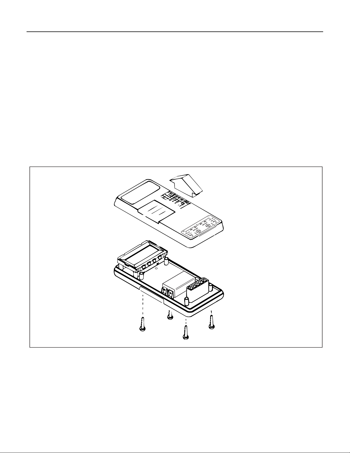
Disassembly/Reassembly
Thermometer disassembly is necessary to replace the battery and some interior parts (see “Replaceable
Parts”, later in this document). Refer to Figure 1 when disassembling and reassembling the thermometer.
To disassemble the thermometer:
1. Turn the thermometer OFF if necessary.
2. Loosen the four bottom case screws and remove the top case.
To reasemble the thermometer:
1. Replace the top case.
2. Tighten the four bottom case screws.
o
C for 24 hours.
Figure 1. Thermometer Disassembly and Reassembly (50D is shown)
4
zf01f.eps
Page 5
Changing the Battery
• Replace the battery as soon as the low battery indicator (N) appears. The
possibility of false readings increases when the battery is not fully charged.
False readings can lead to personal injury.
• To avoid electrical shock, disconnect the thermocouple(s) before opening
the case.
• Do not attempt to recharge the battery.
• To prevent explosion, do not dispose of the battery in fire.
• Follow local laws or regulations when disposing of batteries.
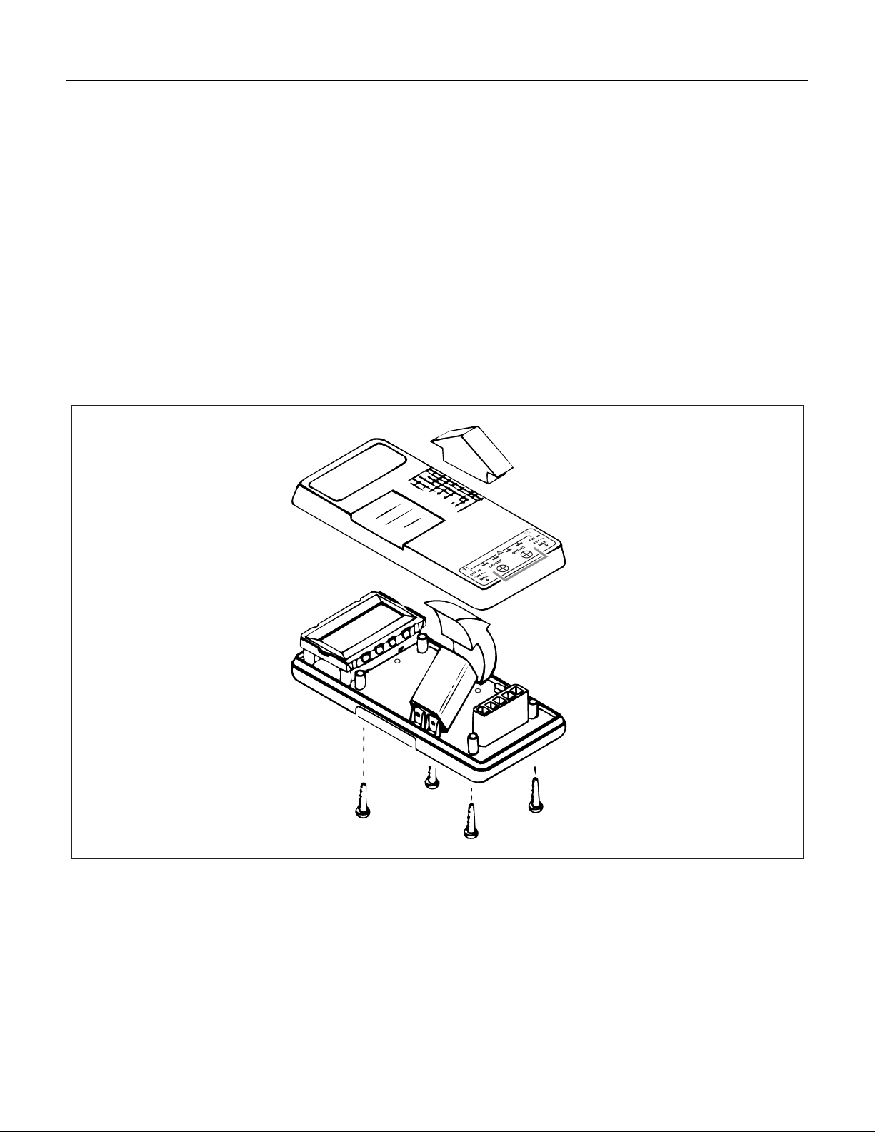
To replace the battery, refer to Figure 2 and the assembly procedures located previously in this document.
Basic Maintenance
WWarning
Caution
Figure 2. Replacing the Battery (50D is shown)
zf02f.eps
5
Page 6

50S & 50D Thermometer
Calibration Information
Required Test Equipment
Table 2 lists the required test equipment needed to perform the performance test and calibration procedures
for the 50S and 50D thermometers. If the required equipment is not available, instruments with equivalent
specifications may be used.
Table 2. Required Test Equipment
Test Equipment Required Characteristics Recommended Model
Fluke 87 Series IV Digital
DMM DC Voltage Accuracy: 0.5%
Temperature Probe Accuracy: Certified to ± 0.2 oC ambient Fluke Model 80T-150U
Output Voltage 0 to 10 V
Accuracy: 0.025%
DC Voltage Calibrator
Elastomeric Switch Pad Fluke Part Number 680686
Thermocouple Connector For K-type thermocouple
Thermocouple Connector For J-type thermocouple
Resolution: 10 µV Fluke 5520A
Multimeter
Fluke 80CK-M
Fluke Part Number 779942
80CJ-M
Fluke Part Number 833046
Thermocouple Wire
(K or J Type) Standard Omega
Dewar Flask/Cap 1-pint capacity Thermos
o
Mercury Thermo meter
o
(either
C or oF)
0.02
0.05
C resolution
o
F resolution
Princo Model ASTM56C
Princo Model ASTM56F
Performance Tests
Performance tests are recommended for incoming inspection, periodic maintenance, and for verifying the
thermometer’s specifications. If the thermometer fails any part of the performance tests, calibration and/or
repair is indicated.
Use the following procedure to prepare the thermometer before beginning the performance tests or
calibration procedures.
o
1. Allow the thermometer to stabilize to room temperature, 23
2. Check the battery and replace it if necessary.
Display Test
Turn the thermometer on while pressing the HOLD button. All display segments are shown until the HOLD
button is released. Check that all the display segments are showing as in Figure 3.
Note
Because pressing the HOLD button during power-up activates one of the thermometers other
functions, take care to return the instrument to its normal function (if necessary).
C ± 5 oC (73 oF ± 9 oF).
6
Page 7

50S Display 50D Display
Performance Tests
KJ
- +
HOLD
F
Figure 3. Display Segments
Wide Range Performance Test Procedure
This test verifies the instrument specifications. If the instrument fails this test, perform the calibration
procedure. If the unit continutes to fail, it should be taken to a Fluke service center.
Ice Bath Construction
To begin the wide range performance test procedure, first construct an ice bath using the following steps:
1. Prepare a Dewar Flask by drilling two holes in its cap to accept the thermometer and thermocouple
wires, or use a standard laboratory cork.
C
KJ
- +
MAXMIN HOLD REC
T1 T2 T1-T2
F
C
zf03f.eps
2. Fill the Dewar Flask with shaved or crushed ice made from distilled water.
3. Fill the Dewar Flask with enough distilled water so that the ice turns to slush, but do not add enough
water to float the ice.
Note
As the ice melts, siphon off the excess water and add more ice. Allow approximately 5 to 10
minutes for the water to drop back to the freezing point.
4. Replace the Dewar Flask cap or cork, and insert the thermocouple wires as shown in Figure 4.
7
Page 8

50S & 50D Thermometer
Calibration Information
50S or 50D
Thermometer +
Thermocouple wire
_
Ice bath
5520A
Copper wire
zf05f.eps
Figure 4. Ice Bath Equipment Connections
Ice Bath Test
Use the following procedure to test the thermometer. This test should be conducted on both thermocouple
inputs of the 50D.
1. Connect the equipment as shown in Figure 4.
2. Insert the Mercury Thermometer to the same depth as the thermocouple wires and verify that the ice
bath temperature is 0.0
3. Short (or apply 0 mV) to the copper wires at the 5520A Calibrator.
4. Verify the thermometer reads 0.0
5. If this test fails, reposition the thermocouple wires and Mercury Thermometer in the ice bath and repeat
steps 2-4. If the test continues to fail, perform the calibration procedure, located later in this document.
6. Remove the short applied in step 3.
7. Using Table 3 (for the corresponding thermocouple type), obtain an output from the 5520A equal to the
first value of the “Input Voltage (mV DC)” column, and verify that the thermometer reads within the
limits specified.
8. Repeat these steps for the remaining voltages in the “Input Voltage (mV DC)” column.
9. Disconnect the thermocouple from the input terminals. This completes the ice bath test.
o
C ± 0.1 oC.
o
C ± 0.4 oC.
8
Page 9

Table 3. Performance Test Values
Calibration
Thermocouple Input Voltage Display Reading
Type (mV DC)
K -5.587 -182.0 ±(0.9) -295.6 ±(1.6)
K -3.211 -89.0 ±(0.8) -128.2 ±(1.4)
K 21.919 530.0 ±(1.2) 986.0 ±(2.3)
K 54.297 1355.0 ±(2.1) 2471.0 ±(3.8)
J -7.824 -197.0 ±(1.0) -322.6 ±(1.7)
J 13.997 258.0 ±(1.1) 496.4 ±(1.9)
J 39.442 705.0 ±(1.5) 1301.0 ±(2.7)
o
C
Calibration
When calibrating the thermometer, refer to Figure 5 for the proper setup connections and Figure 6 for
adjustment locations.
Caution
When directed to short a switch grid in the following procedures, use only the
elastomeric switch pad that is supplied as pca damage may occur if a hard tool
is used.
o
F
Thermometer Calibration
1. Turn the thermometer off and remove the top case leaving the Main PCA in the bottom case.
2. Simultaneously short the TP1 switch grid and turn on the thermometer by shorting the ON/OFF switch
grid. Hold the elastomeric switch pad on TP1 for at least 3 seconds after the thermometer turns on. This
puts the thermometer into the Thermocouple Calibration mode.
3. Allow the thermometer to stabilize at room temperature, 23
4. Select
o
C mode. Select T1 if the thermometer is a Fluke 50D.
5. Adjust the 5520A for 0.00000V. Connect the 5520A output to the TP1 input.
6. Allow the thermometer reading to stabilize. Refer to Figure 6 and adjust the T1 offset adjustment (R7)
for a display reading of 25.2
If you are calibrating a Fluke 50S, skip the next two steps.
7. Leave the 5520A adjusted for 0.00000 V. Connect the 5520A output to the T2 input and select the T2
function.
8. Allow the reading to settle and adjust the T2 offset adjustment (R13) for a display reading of 25.2
0.1
o
C.
9. Adjust the 5520A for 53.807 mV output.
10. Allow the reading to stabilize and adjust (R21) for a display reading of +1370.0
11. Disconnect the thermometer from the 5520A. Turn the thermometer off by shorting the ON/OFF switch
grid.
o
C ± 0.1 oC.
o
C ± 5 oC (73 oF ± 9 oF).
o
C ± 0.4 oC.
o
C ±
12. With an elastomeric switch pad in both hands, use the left pad to short out the TP2 grid, and use the
right pad to first turn on the instrument and then quickly short out the VIEW switch grid. Hold this
9
Page 10

50S & 50D Thermometer
Calibration Information
position until the display is locked in self-test (all LCD segments on). This thermometer is now in the
Reference Junction Sensor calibration mode. Shorting out the VIEW switch grid turns off a filter so that
the reading stabilizes immediately.
13. Using the 80T-150U and the Fluke 87 Series IV Digital Multimeter (DMM), measure the reference
junction transistor temperature by placing the 80T-150U probe tip against Q1, located in the middle hole
of the isothermal block. Wait for the temperature reading to stabilize.
14. Adjust R16 for a temperature reading that is the same as displayed on the DMM.
15. Turn the thermometer OFF by shorting the ON/OFF switch grid, and reattach the top-case.
50S or 50D
Thermometer +
_
Copper
wire
Figure 5. Calibration Connections
5520A
zf07f.eps
10
Page 11

FLUKE 52-1601
Figure 6. A1 Main PCA Adjustments
Optimizing Thermometer Performance in the Negative Temperature Range
Perform the following steps to optimize the thermometer performance in the negative temperature range:
Calibration
zf09f.eps
1. Put the thermometer in normal operating mode. Normal operation can be achieved by turning the
thermometer OFF and then ON. No other thermometer buttons should be pressed during the power cycle
operation.
2. Insert a known good thermocouple in an ice bath (see “Ice Bath Construction” earlier in this document).
3. Insert the Mercury Thermometer to the same depth as the thermocouple wires verifying the ice bath
temperature is 0.0
o
C ± 0.1 oC.
4. Connect the other end of the thermocouple wire to the T1 input of the thermometer and allow the
instrument reading to stabilize.
5. Slowly, and in small increments, adjust R7 (T1 offset) until the thermometer reading matches the
Mercury Thermometer reading. Allow the thermometer reading to stabilize and repeat the adjustment as
necessary until a stable and correct reading can be attained.
6. Repeat steps 4 and 5 for R13 (T2 offset, Fluke 50D only).
Thermocouple Input Calibration (Optional)
This adjustment procedure counteracts the adjustments made in the “Optimizing Performance
in the Negative Temperature Range” section of this document.
This procedure optimizes the 50S or 50D for measurement with a specific thermocouple.
Perform the thermocouple input calibration using the following procedure:
Note
1. Construct an ambient temperature lag bath as shown in Figure 7.
2. Connect the thermocouple to the thermometer input terminals.
3. Select the applicable switch postion (T1 or T2) and temperature scale (
4. Insert the probe into a room temperature lag bath.
o
C or oF).
11
Page 12

50S & 50D Thermometer
Calibration Information
5. Allow the system to stabilize, then adjust T1 or T2 offset adjustments for a temperature display equal to
the reading of the lag bath reference thermometer.
6. Calibration of the thermometers is complete. Disconnect all test equipment from the instrument.
50S or 50D
Thermometer
_
+
Thermocouple wire
Figure 7. Room Temperature Lag Bath
Mercury
thermometer
°C resolution)
(0.02
Lag bath
(room temperature
water)
Immersed to
approximately
same depth
zf06f.eps
12
Page 13

Replaceable Parts
Refer to Table 4 for all replacement part numbers and Figure 8 for part locations. Unless specified in the
“Model Number” column, all parts are for all units. To order replaceable parts, see the “Service Centers”
section of this manual.
Fluke
Item
Number Qty.
Part
Number Description
Replaceable Parts
Table 4. 50S and 50D Replaceable Parts
Model
Number
1
1
2 1 696534 BATTERY, PRIMARY, 9V, 0-15MA All
3 4 832246 SCREW, PH, P, AM THD FORM, STL, 5-14, .750 All
4 1 519116 SCREW, PH, P, THD FORM, STL, 4-24, .250 All
5 4 448456 SCREW, PH, P, AM THD FORM, STL, 4-14, .375 All
61
71
8 1 646653 BRACKET, LCD All
9 1 1280151
10 1 745794 ISOTHERMAL BLOCK All
11 2 649632 CONNECTOR , ELASTOMERIC, LCD TO PWB, 1.900 L All
12 1 761924 BOTTOM SHIELD, MYLAR All
13 4 640565 FOOT, NON-SKID All
14 1 844340 LABEL, WINDOW All
1
778191
778209
1280490
1280483
1280766
1280753
1280160
MAIN PCA
MAIN PCA
CASE, TOP
CASE, TOP
CASE, BOTTOM
CASE, BOTTOM
MASK, BRACKET, FLUKE 50S
MASK, BRACKET, FLUKE 50D
50S
50D
50S
50D
50S
50D
50S
50D
15 1 791343 WINDOW, LCD (BLANK) All
16 1 742205
741314
Not shown12 773135 THERMO COUPLE ASSY, T/C ASSY, K-TYPE, BEADED, MOLDED-PLUG
Not shown 1 1278540 MULTI-LANGUAGE, FLUKE 50S & 50D USERS MANUAL All
Not shown 1 890298 HOLSTER & FLEXSTAND ASSY, YELLOW All
LCD FLUKE-51, LCD, 5 DIGIT, TEMPERATURE, MULTIPLEXED
LCD FLUKE-52, LCD, 5 DIGIT, TEMPERATURE, MULTIPLEXED
50S
50D
50S
50D
13
Page 14

50S & 50D Thermometer
Calibration Information
4X
5
12
7
15
6
2
10
9
4
16
1
8
13
3
4X
Figure 8. Exploded View Diagram (Model 50D is Shown)
11
2X
4X
zf08f.eps
14
 Loading...