

Page 1

medTester 5000C
Biomedical Tester
Operators Manual
PN 2243153
February 2006
2006 Fluke Corporation, All rights reserved. Printed in USA
All product names are trademarks of their respective companies.
Page 2

Warranty and Product Support
Fluke Biomedical warrants this instrument against defects in materials and workmanship for one full
year from the date of original purchase. During the warranty period, we will repair or, at our option,
replace at no charge a product that proves to be defective, provided you return the product,
shipping prepaid, to Fluke Biomedical. This warranty does not apply if the product has been
damaged by accident or misuse or as the result of service or modification by other than Fluke
Biomedical. IN NO EVENT SHALL FLUKE BIOMEDICAL BE LIABLE FOR
CONSEQUENTIAL DAMAGES.
Only serialized products and their accessory items (those products and items bearing a distinct serial
number tag) are covered under this one–year warranty. PHYSICAL DAMAGE CAUSED BY
MISUSE OR PHYSICAL ABUSE IS NOT COVERED UNDER THE WARRANTY. Items such
as cables and nonserialized modules are not covered under this warranty.
Recalibration of instruments is not covered under the warranty.
This warranty gives you specific legal rights, and you may also have other rights which vary from
state to state, province to province, or country to country. This warranty is limited to repairing the
instrument to Fluke Biomedical’s specifications.
Warranty Disclaimer
Should you elect to have your instrument serviced and/or calibrated by someone other than Fluke
Biomedical, please be advised that the original warranty covering your product becomes void when
the tamper-resistant Quality Seal is removed or broken without proper factory authorization. We
strongly recommend, therefore, that you send your instrument to Fluke Biomedical for factory
service and calibration, especially during the original warranty period.
Page 3

Notices
All Rights Reserved
Copyright 2006, Fluke Biomedical. No part of this publication may be reproduced, transmitted,
transcribed, stored in a retrieval system, or translated into any language without the written
permission of Fluke Biomedical.
Copyright Release
Fluke Biomedical agrees to a limited copyright release that allows you to reproduce manuals and
other printed materials for use in service training programs and other technical publications. If you
would like other reproductions or distributions, submit a written request to Fluke Biomedical.
Unpacking and Inspection
Follow standard receiving practices upon receipt of the instrument. Check the shipping carton for
damage. If damage is found, stop unpacking the instrument. Notify the carrier and ask for an agent
to be present while the instrument is unpacked. There are no special unpacking instructions, but be
careful not to damage the instrument when unpacking it. Inspect the instrument for physical
damage such as bent or broken parts, dents, or scratches.
Technical Support
For application support or answers to technical questions, either email
techservices@flukebiomedical.com or call 1-800- 648-7952 or 1-425-446-6945.
Claims
Our routine method of shipment is via common carrier, FOB origin. Upon delivery, if physical
damage is found, retain all packing materials in their original condition and contact the carrier
immediately to file a claim. If the instrument is delivered in good physical condition but does not
operate within specifications, or if there are any other problems not caused by shipping damage,
please contact Fluke Biomedical or your local sales representative.
Standard Terms and Conditions
Refunds and Credits
Please note that only serialized products and their accessory items (i.e., products and items
bearing a distinct serial number tag) are eligible for partial refund and/or credit. Nonserialized
parts and accessory items (e.g., cables, carrying cases, auxiliary modules, etc.) are not eligible
for return or refund. Only products returned within 90 days from the date of original purchase are
eligible for refund/credit. In order to receive a partial refund/credit of a product purchase price on
a serialized product, the product must not have been damaged by the customer or by the carrier
chosen by the customer to return the goods, and the product must be returned complete (meaning
with all manuals, cables, accessories, etc.) and in “as new” and resalable condition. Products not
returned within 90 days of purchase, or products which are not in “as new” and resalable condition,
are not eligible for credit return and will be returned to the customer. The Return Procedure (see
below) must be followed to assure prompt refund/credit.
Page 4

Restocking Charges
Products returned within 30 days of original purchase are subject to a minimum restocking fee
of 15 %. Products returned in excess of 30 days after purchase, but prior to 90 days, are
subject to a minimum restocking fee of 20 %. Additional charges for damage and/or missing
parts and accessories will be applied to all returns.
Return Procedure
All items being returned (including all warranty-claim shipments) must be sent freight-prepaid to
our factory location. When you return an instrument to Fluke Biomedical, we recommend using
United Parcel Service, Federal Express, or Air Parcel Post. We also recommend that you insure
your shipment for its actual replacement cost. Fluke Biomedical will not be responsible for lost
shipments or instruments that are received in damaged condition due to improper packaging or
handling.
Use the original carton and packaging material for shipment. If they are not available, we
recommend the following guide for repackaging:
Use a double–walled carton of sufficient strength for the weight being shipped.
Use heavy paper or cardboard to protect all instrument surfaces. Use nonabrasive material
around all projecting parts.
Use at least four inches of tightly packed, industry-approved, shock-absorbent material
around the instrument.
Returns for partial refund/credit:
Every product returned for refund/credit must be accompanied by a Return Material
Authorization (RMA) number, obtained from our Order Entry Group at 1-800-648-7952 or 1425-446-6945.
Repair and calibration:
To find the nearest service center, goto www.flukebiomedical.com/service or
In the U.S.A.:
Cleveland Calibration Lab
Tel: 1-800-850-4606
Email: globalcal@flukebiomedical.com
Everett Calibration Lab
Tel: 1-888-99 FLUKE (1-888-993-5853)
Email: service.status@fluke.com
In Europe, Middle East, and Africa:
Eindhoven Calibration Lab
Tel: +31-402-675300
Email: ServiceDesk@fluke.com
In Asia:
Everett Calibration Lab
Tel: +425-446-6945
Email: service.international@fluke.com
Certification
This instrument was thoroughly tested and inspected. It was found to meet Fluke Biomedical’s
manufacturing specifications when it was shipped from the factory. Calibration measurements are
Page 5

traceable to the National Institute of Standards and Technology (NIST). Devices for which there
are no NIST calibration standards are measured against in-house performance standards using
accepted test procedures.
WARNING
Unauthorized user modifications or application beyond the published specifications may result in
electrical shock hazards or improper operation. Fluke Biomedical will not be responsible for any
injuries sustained due to unauthorized equipment modifications.
Restrictions and Liabilities
Information in this document is subject to change and does not represent a commitment by
Fluke Biomedical. Changes made to the information in this document will be incorporated in
new editions of the publication. No responsibility is assumed by Fluke Biomedical for the use
or reliability of software or equipment that is not supplied by Fluke Biomedical, or by its
affiliated dealers.
Manufacturing Location
The medTester 5000C is manufactured in Everett, WA, U.S.A.
Page 6

Page 7

Biomedical Test System
Contents
Table of Contents
1: GENERAL INFORMATION
SAFETY CONSIDERATIONS .......................................................... 1-1
General.....................................................................................1-1
Safety Symbols ........................................................................1-1
Introduction ..................................................................................1-2
How to Use This Manual...............................................................1-3
If You’ve Used The medTester 5000C Before... ......................1-3
If You’re New to The medTester 5000C... ...............................1-3
Where to Find Help ..................................................................1-4
Features........................................................................................1-5
Electrical Safety Testing .........................................................1-5
Performance Testing ...............................................................1-5
Manual Measurements............................................................. 1-5
Automatic Measurements........................................................1-5
Computer Control..................................................................... 1-6
medCheck ................................................................................1-6
medTester 5000C Optional Modules ............................................1-7
Features......................................................................................1-11
Optional Accessories .................................................................1-11
medTester 5000C Instrument Specifications ............................ 1-12
Line Voltage and Measurements ...........................................1-12
Leakage Current ....................................................................1-12
Equipment Current................................................................. 1-13
Resistance .............................................................................1-13
Isolated Power ....................................................................... 1-13
Toolbox ..................................................................................1-14
Test Receptacle..................................................................... 1-14
Ground Fault Circuit Interrupter............................................ 1-15
Performance Waveforms........................................................1-15
General Specifications ...............................................................1-16
ECG Connections ................................................................... 1-16
Data Input and Output ...........................................................1-16
RS-232C Serial Interface Parameters....................................1-16
Real Time Clock.....................................................................1-16
Accessories ................................................................................ 1-17
medTester 5000C Module Upgrades .....................................1-19
2: INSTALLATION
Factory Default Settings ..............................................................2-1
Power-Up Sequence .....................................................................2-2
Initialization..................................................................................2-3
Page 8

Date and Time Setup ................................................................... 2-3
Audio Transducer......................................................................... 2-4
Enabling Modules ......................................................................... 2-5
Confirming Module Installation ............................................... 2-7
3: INSTRUMENT FAMILIARITY
Know Your medTester 5000C ...................................................... 3-1
Top Panel Controls, Displays, and Connectors....................... 3-1
Rear Panel Controls, Displays, and Connectors ..................... 3-3
Power Up ................................................................................. 3-4
Navigating the Menus ............................................................. 3-4
4: MANUAL TESTS
Performing Manual Tests ........................................................... 4-35
Printing Manual Measurements ............................................ 4-35
Line Voltage .......................................................................... 4-35
Leakage Current.................................................................... 4-36
ECG Lead Leakage ................................................................ 4-38
Equipment Current ................................................................ 4-42
Resistance............................................................................. 4-42
Isolated Power and Ground Fault Test ................................. 4-44
Toolbox.................................................................................. 4-45
5: AUTOSEQUENCES
What Is an Autosequence ............................................................ 5-1
Description of Standard Safety Autosequences ......................... 5-2
Autosequence Selection ......................................................... 5-3
Standard Safety Autosequence Names .................................. 5-4
Autosequence Device Prompts ............................................... 5-5
Autosequence Steps .................................................................... 5-7
System Line Voltage ............................................................... 5-8
Power Cord Resistance........................................................... 5-8
Leakage Current Measurements............................................. 5-9
Equipment Current Measurement ........................................... 5-9
ECG Performance Waveforms ............................................... 5-10
End-of-Test Prompts.............................................................. 5-11
Test Tag Printer ......................................................................... 5-13
Optional Monitoring Autosequences ......................................... 5-15
Line Voltage Monitor ............................................................. 5-16
Environmental Monitor .......................................................... 5-17
Toolbox Monitors ....................................................................... 5-19
Temperature Monitor ............................................................ 5-19
Humidity Monitor ................................................................... 5-21
6: CUSTOMIZE YOUR MEDTESTER
How to Customize a Preprogrammed Safety Autosequence ...... 6-1
Page 9

Biomedical Test System
Contents
What You See in an Autosequence..........................................6-2
How to Customize....................................................................6-3
Customizing a Blank Safety Autosequence ................................. 6-7
Test Record Header......................................................................6-7
Customizing Your Autosequence Prompts................................... 6-8
Turning Prompts On and Off .........................................................6-9
Renaming Prompts .....................................................................6-10
Pausing .......................................................................................6-11
Test Tag Configuration...............................................................6-11
Summary of Stored Records....................................................... 6-12
Customizing Bar Code Record Data Entry .................................6-13
Resetting Autosequences to Default Settings........................... 6-14
Printing Your medTester 5000C Configuration ..........................6-15
Customize medTester 5000C Options........................................6-15
7: PERFORMANCE WAVES
Outputting Performance Waves ...................................................7-1
Waveform Groups .........................................................................7-2
Running Waveforms from The WAVES Menu................................7-4
Conducting Waveform Tests in Safety Autosequences...............7-5
8: MEMORY
Introduction .................................................................................. 8-1
Viewing A Single Record ..............................................................8-2
Printing Records ...........................................................................8-2
Print A Single Record............................................................... 8-2
Print A Range of Records.........................................................8-3
Print All Records ......................................................................8-3
Print Records by Type..............................................................8-3
Printing A Summary of Records...............................................8-5
Printing Failed Test Records ...................................................8-5
Configuring Your Printer...............................................................8-5
Deleting Records .....................................................................8-6
Erasing Memory, All Records, and Checklists ........................8-6
Checking Contents of Memory ..................................................... 8-6
Searching for Records .................................................................. 8-7
Searching for Records with Test Failures............................... 8-8
Printing Checklists ..................................................................8-8
Keyboard Shortcut Commands.....................................................8-9
9: DEFIBRILLATOR MODULE
Defibrillator Autosequences......................................................... 9-1
Defibrillator Autosequence Names..........................................9-3
Running Defibrillator Autosequence Tests .................................. 9-5
Pretest Device Prompts ........................................................... 9-6
Page 10

Test Sequence......................................................................... 9-7
Posttest Prompts................................................................... 9-12
Customizing Defibrillator Autosequences ................................. 9-12
Make Your Own Autosequence ............................................. 9-12
10: IV PUMP MODULE
IV Pump Autosequences............................................................ 10-1
Basic Test Format ................................................................. 10-1
IV Pump Analyzers ................................................................ 10-2
IV Pump Autosequence Names ................................................. 10-4
Running IV Pump Autosequences.............................................. 10-7
Select the Autosequence...................................................... 10-7
Pretest Device Prompts ........................................................ 10-7
IV PUMP TESTS.......................................................................... 10-9
Infutest 2000 Series D........................................................... 10-9
IPT-1 .................................................................................... 10-12
IPT-MC ................................................................................. 10-12
IDA 4 Plus ............................................................................ 10-13
Pressure Test (Infutest, IPT-1, IPT-MC and IDA 4 Plus) ..... 10-17
Posttest Prompts................................................................. 10-18
Customizing IV Pump Tests..................................................... 10-22
Make Your Own Autosequence ........................................... 10-22
Making an Autosequence.................................................... 10-23
Infutest ................................................................................ 10-23
IPT-1 .................................................................................... 10-25
IPT-MC ................................................................................. 10-26
Print Your Autosequence .................................................... 10-26
Reinitialize Factory Default Settings .................................. 10-26
11: MEDCHECK MODULE
Tap Your medTester’s Potential ................................................ 11-1
What’s a Checklist? ................................................................... 11-2
Understanding and Using Checklists ........................................ 11-3
You’ve Made a Checklist—Now What? ...................................... 11-6
Running Checklists in medTester 5000C .................................. 11-6
Find a Checklist..................................................................... 11-7
Run a Checklist ..................................................................... 11-7
Items in a Checklist .............................................................. 11-9
View or Print a Checklist .................................................... 11-12
Remote Control of Fluke Biomedical Testers ......................... 11-13
12: REMOTE OPERATION
Local Versus Remote Mode ....................................................... 12-1
Communicating through medTester Serial Ports ................. 12-1
Communications Settings ..................................................... 12-2
Page 11

Biomedical Test System
Contents
Local Input Mode ........................................................................12-3
Local Output for Records and Tags ...........................................12-4
Record Output........................................................................12-5
Test Tag Output .....................................................................12-5
Remote Mode.............................................................................. 12-6
Going Remote ........................................................................12-6
File Transfer Protocol ............................................................12-9
Remote Commands List ...........................................................12-12
Port Diagnostics ....................................................................... 12-17
13: THE WEDGE ADAPTER
Features of the Wedge ...............................................................13-1
Serial Port Expansion .................................................................13-2
Keyboard Interface.....................................................................13-2
Port Configuration ......................................................................13-2
Installing the Wedge...................................................................13-4
Disassembly of the medTester 5000C’s Feet and Tilt Bail ...13-5
Attaching the Wedge to the medTester 5000C .....................13-5
Operating the Wedge .................................................................. 13-7
Wedge Port Names ................................................................13-7
Enabling The Wedge ..............................................................13-7
Configuring Wedge Ports .......................................................13-7
Configuring One Port for Two Purposes ..............................13-11
Setting Baud Rates................................................................... 13-11
Setting Output Ports.................................................................13-13
14: ESU MODULE
ESU Autosequences ...................................................................14-1
ESU Autosequence Names ....................................................14-4
Running ESU Autosequence Tests.............................................14-5
Pretest Device Prompts ......................................................... 14-6
Test Sequence ....................................................................... 14-7
ESU Test Types......................................................................14-7
ESU Autosequence Descriptions..............................................14-10
Posttest Prompts ................................................................. 14-14
Customizing ESU Autosequences ............................................ 14-15
Make Your Own Autosequence ...........................................14-15
SPO2 MODULE
SPO2 Autosequences .................................................................15-1
SPO2 Autosequence Names .................................................. 15-4
Running SPO2 Autosequence Tests...........................................15-6
Pretest Device Prompts ......................................................... 15-8
Test Sequence ....................................................................... 15-9
Probe Test............................................................................15-12
Page 12

For the Oxitest PLUS: .............................................................. 15-13
For CardioSat 100: ................................................................... 15-16
For the Index 2XL:.................................................................... 15-19
Posttest Prompts................................................................. 15-22
Customizing SPO2 Autosequences.......................................... 15-22
Make Your Own Autosequence ........................................... 15-22
Configuring for Your SPO2 Simulator.................................. 15-23
Making an Autosequence.................................................... 15-23
16: TRANSCUTANEOUS
PACEMAKER (PACER) MODULE
Pacer Autosequences ................................................................ 16-1
Pacer Autosequence Names ................................................. 16-3
Running Pacer Autosequence Tests.......................................... 16-4
Pretest Device Prompts ........................................................ 16-5
Test Sequence....................................................................... 16-6
Posttest Prompts................................................................. 16-14
Customizing Pacer Autosequences ......................................... 16-15
Make Your Own Autosequence ........................................... 16-15
17: NON-INVASIVE BLOOD
PRESSURE (NIBP) MODULE
NIBP Autosequences ................................................................. 17-1
NIBP Autosequence Names .................................................. 17-3
Running NIBP Autosequence Tests........................................... 17-4
Pretest Device Prompts ........................................................ 17-5
Test Sequence....................................................................... 17-6
Posttest Prompts................................................................. 17-11
Customizing NIBP Autosequences .......................................... 17-12
Make Your Own Autosequence ........................................... 17-12
Page 13

Chapter 1
General Information
In this chapter you will learn how to use this manual,
where to get help, and about medTester 5000C Features
and Specifications.
SAFETY CONSIDERATIONS
General
This instrument and related documentation must be reviewed for
familiarization with safety markings and instructions before you operate the
instrument. Refer to the medTester 5000C Operators Manual for operating
instructions.
Safety Symbols
The symbol to the left is the operators manual symbol. When
!
you see this symbol on the instrument, refer to the operators
manual.
WARNING! Denotes a hazard. WARNING! calls attention to a procedure,
practice, or the like, which, if not correctly performed or adhered to, could
result in personal injury. Do not proceed beyond a WARNING! sign until the
indicated conditions are fully understood and met.
CAUTION. Denotes a hazard. CAUTION calls attention to a procedure,
practice, or the like, which, if not correctly performed or adhered to, could
result in damage to or destruction of part or all of the instrument. Do not
proceed beyond a CAUTION sign until the indicated conditions are fully
understood and met.
1-1
Page 14

medTester 5000C
Operators Manual
Introduction
This manual is written for the biomedical technician or clinical engineer
responsible for testing hospital equipment, or the plant maintenance
technician responsible for maintenance records.
The medTester 5000C is an automated biomedical equipment test system and
a portable data acquisition unit that can be controlled with a computer. You
can expand the capabilities of the base model by adding modules that let you
store test records to memory and print them out.
The medTester 5000C is designed to measure electrical current and resistance
as they relate to electrical safety. It measures conditions that might cause
injury for compliance with the specifications set forth by ANSI, NFPA, and
AAMI.
The medTester 5000C base model automates repetitive tasks with safety
autosequences for medical equipment, including lead tests on patient
monitors, as well as general electrical devices. You can customize
autosequences to meet your specific testing needs.
With the addition of optional modules (for example, the RS-232/Printer
module, 100 Record Memory module, Expanded Memory module, and the
Waveform/Extended Testing module) your medTester 5000C becomes even
more powerful. The Waveform/Extended Testing module gives you
additional safety autosequences and performance wave and arrhythmia
generation capabilities. Individual defibrillation and IV pump modules offer
safety and performance testing autosequences for those devices.
With the Data Transfer module, you can transfer stored equipment test
record files to a compatible database program, Computerized Maintenance
Management System (CMMS) or Equipment Management System (EMS).
The medCheck module enables the downloading of test checklists and the
uploading of data to your database, CMMS, or EMS.
Finally, in addition to operating your medTester 5000C in the local mode
from the keyboard, bar code port, or the optional external keyboard, you can
also operate it from a remote location. Remote operation can take place from
a remote personal computer or from a compatible terminal device.
With the Wedge adapter, you can expand the number of serial ports to
control several external instruments without changing setups. In addition, you
can connect a PC-style keyboard to the Wedge adapter for entering data more
easily.
1-2
Page 15

Biomedical Test System
General Information
The medTester 5000C—reliable safety and performance testing. Capable of
managing your entire equipment program.
How to Use This Manual
Your medTester 5000C Operators Manual is designed for you. Whether you
are an experienced medTester operator or someone new to medTester, please
read this section before using your medTester 5000C.
If You’ve Used The medTester 5000C Before...
The medTester 5000C has been substantially upgraded to best satisfy your
needs. It now uses a new firmware release that offers increased reliability and
more consistent and stable data storage. RAM in the medTester 5000C is
dynamic, and data retrieval is simplified. In addition, some features that you
may be using have been enhanced with new features for your convenience.
Note in particular these chapters:
• Chapter 1 introduces the medTester 5000C’s enhanced features.
1
• Chapter 3 shows you how to navigate the medTester’s menus.
• Chapter 6 helps you customize autosequences.
• Chapters 11 and 12 bring you up to date on medCheck checklists
remote operation of the medTester 5000C.
If You’re New to The medTester 5000C...
Welcome to the medTester 5000C! It is the easy-to-use electrical safety and
performance analyzer with a high-quality data collection and retrieval
system—all designed to make your job easier and more productive. While the
ideal recommendation to a new user is to read the entire manual, we know
that you want to start using your new medTester now. Before you do, please
review Chapters 1 to 3 to learn about the medTester 5000C. Other chapters
of interest to you might be:
• Chapter 4 for information about basic medTester 5000C safety
test measurements.
• Chapter 5 for autosequences.
1-3
Page 16

medTester 5000C
Operators Manual
Where to Find Help
If you have questions not answered in this manual, please refer to the
following Fluke Biomedical sources:
• medTester 5000C Service Manual, Part No. 2243166.
• Fluke Biomedical Customer Service Department. Telephone
800-648-7952
• Safe current limits for electromedical apparatus, (ANSI/AAMI ES1),
© 1993, Association for the Advancement of Medical
Instrumentation.
ISBN 1-57020-007-6.
AAMI Phone: 800-332-2264.
• Standard for Health Care Facilities, (NFPA 99), 1993 Edition,
© 1993, National Fire Protection Association, February 12, 1993,
NFPA.
NFPA Phone: 800-344-3555.
1-4
Page 17

Biomedical Test System
General Information
Features
The medTester 5000C is an automated biomedical equipment test system
designed for you to do electrical safety and performance testing. With the
medTester, you can run customizable automatic sequences of tests, called
autosequences. You can print stored test records or upload them to a
computer. A computer can operate a medTester 5000C from a remote
location. This section defines some basic concepts behind the testing that this
manual describes.
Electrical Safety Testing
The medTester 5000C measures electrical current and resistance related to
electrical safety. Electrical safety testing is the measurement of electric
conditions that could result in injury to operators of that equipment or to
patients. All measurements you make with the medTester 5000C comply with
specifications set forth by ANSI, NFPA, and AAMI.
Performance Testing
Performance testing verifies that equipment performs to manufacturer
specifications. Different types of medical equipment require tests that are
unique to its operation—patient monitors, defibrillators, and IV pumps, to
name just a few. The medTester 5000C provides ECG waveforms for
performance testing of patient monitors. With optional autosequence
modules, you can use analyzers to test the performance of defibrillators, IV
pumps, electrosurgical units, pulse oximeter analyzers and more.
1
Manual Measurements
You can always perform safety measurements on any electrical equipment
directly from the medTester keyboard. Measurements appear on the display
continuously until you escape from the test. Instructions for conducting
manual tests are in Chapter 4, Manual Tests.
Automatic Measurements
One of the strengths of the medTester 5000C is the ability to automate
testing using autosequences. Autosequences are collections of tests that
execute as a group. Ten safety autosequences ship with the medTester 5000C
base model, each of which you can customize to meet your needs. With the
Waveform/Extended Testing Module, you receive an additional five
customizable safety autosequences, five ECG performance waveform and
arrhythmia groups, and line monitor and environmental autosequences.
1-5
Page 18

medTester 5000C
Operators Manual
Prompts in the autosequence ask you for information that aids in test
reporting. The pretest prompts, for example, can ask you for the model and
serial number of the equipment you’re testing, the test location, operator
code, and physical condition of the EUT (equipment under test). Posttest
prompts can ask you to schedule the next test date, input comments about the
tests, or prepare a test tag.
With the Memory Module and RS-232/Printer Module installed on your
medTester 5000C, you can store test records to memory and print them from
the medTester’s printer port. Additional autosequence modules are available
for performance testing defibrillators, IV pumps, and more. See Chapter 5,
Autosequences.
Computer Control
You can remotely control your medTester 5000C from a personal computer
or compatible terminal device through a serial communication port and
appropriate communication software. Once connected and in remote control of
the medTester 5000C, you send remote commands to the medTester 5000C
to do safety and performance tests, with the results returned to the computer.
Some medTester 5000C users prefer to accumulate the test data for
equipment before reporting stored records. Then at their convenience they
upload the data to an equipment database program, Computerized
Maintenance Management System, or Equipment Management System (EMS)
on a computer. This is accomplished through a serial port on the
medTester 5000C and the medTester 5000C’s Data Transfer Module. Chapter
12, Remote Operation, discusses the methods you can use to control the
medTester 5000C and to manage test data.
If you use other Fluke Biomedical analyzers, such as the Impulse 4000 or IPT1, you can control them with the medTester 5000C. By connecting an
analyzer to the medTester 5000C’s COM2 port, you gain a two-way
communication link. This link lets the medTester 5000C control the
operation of the analyzer. Test data that the analyzer collects is then returned
to storage in the medTester 5000C.
medCheck
The medTester 5000C medCheck Module unleashes the power of the
medTester 5000C to become the centerpiece of a total equipment
management solution. medCheck lets you download checklists from, and
upload checklist test data to, your equipment management software system.
1-6
Page 19

Biomedical Test System
General Information
Checklists are complete sets of preventive maintenance procedures for
equipment testing. They can contain prompts to the medTester 5000C user to
make physical inspections of the EUT and to take individual safety
measurements. A checklist can include one or more safety and performance
autosequences that automatically execute. Checklist test record data is then
uploaded to the user’s equipment management database program,
Computerized Maintenance Management System. See Chapter 11, medCheck
Module, for more information.
medTester 5000C Optional Modules
The medTester 5000C offers several modules as options. (See the table later
in this chapter.) If your medTester 5000C includes any of these modules, they
are listed under the
Enter these menu commands:
1. From the main menu, press:
UTIL menu. To access the menu, do the following:
1
UTIL
F5
2. Press the right arrow to scroll to the remaining menus.
MODULES
3. Press:
NOTE
F3
For further information about using medTester 5000C menus
and function keys, see Navigating the Menus, in Chapter 3,
Instrument Familiarity.
Whenever you attempt to select a module that is not installed, this message
appears in the display:
MODULE NOT INSTALLED
1-7
Page 20

medTester 5000C
Operators Manual
These modules are software enabled for use by the medTester’s firmware.
The firmware is held in EPROM (erasable programmable read-only memory).
When you purchase one or more of the modules described below, you receive
a 3.5-inch floppy diskette containing the software functions of the module.
To load the module software, attach the appropriate serial cable from a
communications port on your personal computer to a communications port
on the medTester.
Once this connection is made, you receive instructions for enabling the
module in the medTester 5000C’s EEPROM (electrically erasable
programmable read-only memory).
medTester 5000C Modules
medTester
5000C
Module Name
RS-232/Printer
Memory—
100 Records
Memory—
Expanded
Waveform/
Extended Testing
Functions Enabled medTester
Prerequisites for Use of
Module
• Use of COM1 and
COM2 serial ports.
• Use of the parallel
printer port.
• Test record
storage.
• Storage of
autosequence and
medCheck data.
• Five (5) additional
safety
autosequences.
• ECG performance
waveforms.
• ECG arrhythmias.
• None • Remote operation of the
• RS-232/Printer Module • Storing of test records.
• RS-232/Printer Module.
• Memory—100 Records
Module.
• RS-232/Printer Module.
• Memory—100 Records
Module.
Required for...
medTester 5000C from a
personal computer or
compatible terminal device.
• Two-way communication
between the
medTester 5000C and a Fluke
Biomedical analyzer or tester.
• Input from an optional
keyboard, bar code scanning
gun.
• Printing test record output.
• Autosequence testing.
• Use of medCheck.
• Adding more customized
safety autosequences.
• Outputting ECG waveforms to
patient monitors.
• Outputting ECG arrhythmias to
patient monitors.
1-8
• Line monitor test.
• Environmental test.
• Periodic measurements of line
voltage.
• Measuring ground potential
and resistance between a
common ground point and
multiple points in a room.
Page 21

Biomedical Test System
General Information
medTester 5000C Modules
1
medTester
5000C
Module Name
Data Transfer
medCheck
Defibrillator
IV Pump
Functions Enabled medTester
Prerequisites for Use of
Module
• File Transfer
Protocol used to
transfer checklists
into and out of the
medTester 5000C.
• Checklists • RS-232/Printer Module.
• Defibrillation
autosequences.
• IV Pump
autosequences.
• RS-232/Printer Module.
• Memory—100 Records
Module.
• Memory—100 Records
Module.
• Expanded Memory
Module.
• Data Transfer Module.
• RS-232/Printer Module.
• Memory—100 Records
Module.
• Expanded Memory
Module.
• Data Transfer Module.
• RS-232/Printer Module.
• Memory—100 Records
Module.
• Expanded Memory
Module.
Required for...
• Checklist usage.
• Communicating checklists
between an equipment
management database system
and the medTester 5000C.
• 20 autosequences for testing
defibrillators with the Fluke
Biomedical Impulse 4000
defibrillator analyzer.
• Including defibrillator
autosequences in checklists.
• 10 autosequences for testing
IV pumps with the Fluke
Biomedical pump tester.
• Including IV pump
autosequences in checklists.
• Data Transfer Module.
ESU
• ESU
autosequences.
• RS-232/Printer Module.
• Memory—100 Records
Module.
• Expanded Memory
Module.
• Data Transfer Module.
• 10 autosequences for testing
electrosurgical units with Fluke
Biomedical analyzers.
• Including ESU autosequences
in checklists.
1-9
Page 22

medTester 5000C
Operators Manual
medTester 5000C Modules
medTester
5000C
Module Name
SPO2
Pacer
NIBP
Functions Enabled medTester
Prerequisites for Use of
Module
• SPO2
autosequences.
• Transcutaneous
Pacemaker
autosequences.
• Non-Invasive Blood
Pressure
autosequences.
• RS-232/Printer Module.
• Memory—100 Records
Module.
• Expanded Memory
Module.
• Data Transfer Module.
• RS-232/Printer Module.
• Memory—100 Records
Module.
• Expanded Memory
Module.
• Data Transfer Module.
• RS-232/Printer Module.
• Memory—100 Records
Module.
• Expanded Memory
Module.
• Data Transfer Module.
Required for...
• 10 autosequences for testing
SPO2 monitors with Fluke
Biomedical analyzers.
• Including SPO2
autosequences in checklists.
• 10 autosequences for testing
transcutaneous pacemakers
with the Fluke Biomedical
Impulse 4000.
• Including Pacer
autosequences in checklists.
• 10 autosequences for testing
Non-Invasive Blood Pressure
monitors with the Fluke
Biomedical CuffLink.
• Including NIBP pump
autosequences in checklists.
Bar Code
(hardware)
• Scanning of bar
code data into test
record.
• None • Scanning of data.
1-10
Page 23

Biomedical Test System
General Information
Features
• Fully automated electrical safety testing
• 12–lead ECG/arrhythmia simulation
• Dedicated “autosequence” testing for performance testing of
defibrillators, infusion pumps, etc.
• 20-ampere testing with GFCI protection
• Meets ANSI/AAMI ES1–1993 test load requirements
• Load current measurement
• Programmable test limits
• Automatic record storage
• Bar code compatibility
1
Optional Accessories
• External RS-232 Keyboard
• Bar Code Scanner (requires Wedge adapter)
• Wedge Adapter (eight 25-pin serial ports as well as AT or PS/2
keyboard port)
• Mini PC-Style Keyboard (AT or PS/2, requires Wedge adapter)
• Label Printer
1-11
Page 24

medTester 5000C
Operators Manual
medTester 5000C Instrument Specifications
Line Voltage and Measurements
• Hot to Neutral.
• Neutral to Ground.
• Hot to Ground.
• Range: 200.0 V RMS.
• Accuracy: ±5% of range.
Leakage Current
Leakage current is measured through a 1 kΩ AAMI load RMS or DC
measured and displayed in microamperes. These tests can be thought of as
measuring the voltage, in millivolts across the same load.
Leakage Current Measurements
• Case external.
• Case internal.
• External.
• ECG—Leads are RL, RA, LA, LL, and V1-V6 tied together:
1. To ground, all leads or individual leads.
2. Lead to lead, individual leads to all other leads together.
3. Lead isolation (RMS only), all leads or individual leads.
This test is with line voltage applied from the lead(s) to
ground, current limited by 120 kΩ.
1-12
Note
If you receive abnormally high leakage current measurements
with V1-V6 leads tied together, you can inspect individual V
leads by removing the other leads. This procedure allows you to
isolate the lead with a high leakage current reading.
Page 25
Biomedical Test System
µ
General Information
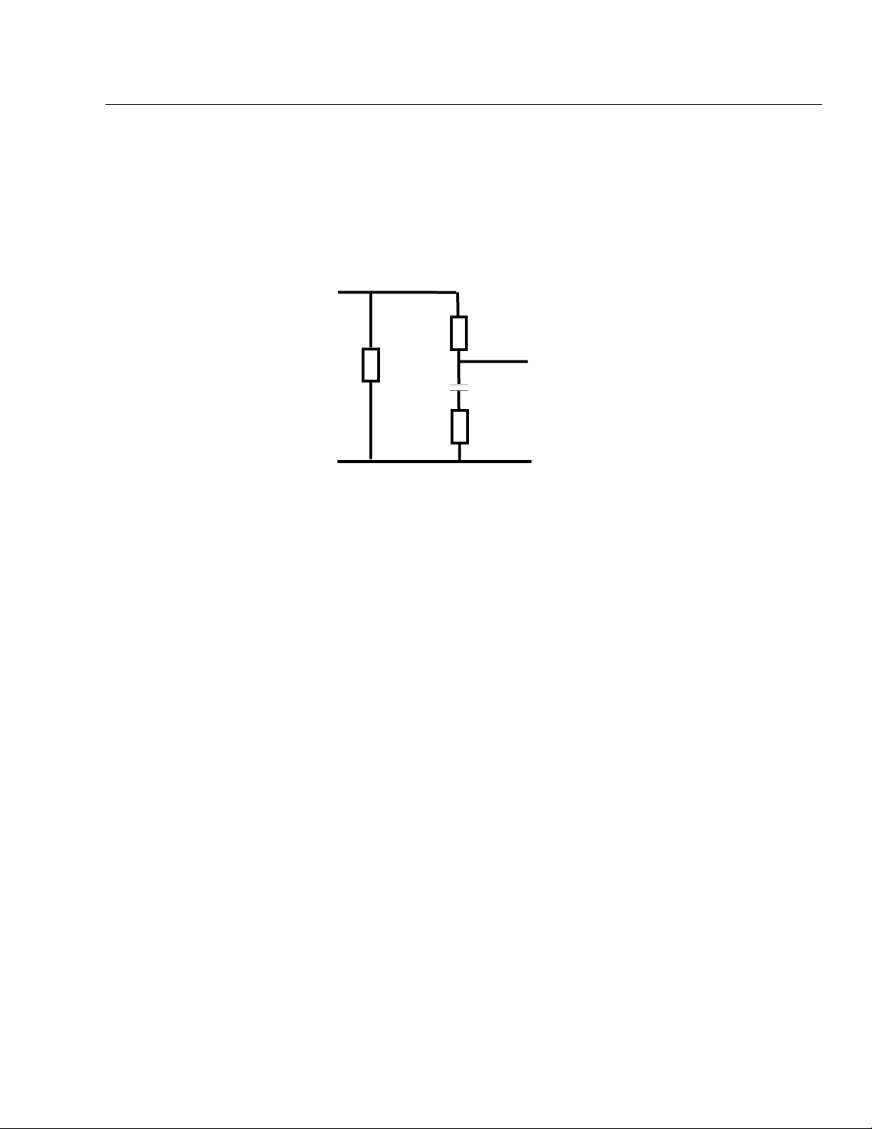
AAMI Load
• Simulated patient load recommended by the Association for the
Advancement of Medical Instrumentation (AAMI), Safe Current
Limits Standard (ANSI/AAMI ES1-1993) (revision of the earlier
ANSI/AAMI ES1-1985 and SCL-12/78).
• AAMI Load drawing:
1
LEAKAGE
CURRENT
INPUT
1 KΩ
10 KΩ
0.015
100 Ω
F
OUTPUT TO
METER
CIRCUIT
• Frequency Response: ANSI/AAMI ES1-1993
• Test Load Impedance: 1000 ohms +/- 1% @ DC
(ANSI/AAMI ES1-1993)
• Ranges—2000 µA and 200 µA.
• Range—20.00 A RMS.
• Accuracy—± 1.0% of reading DC and from 48 Hz to 1kHz
± 2.5% of reading 1 kHz to 100 kHz
± 5.0% of reading 100 kHz to 1 MHz
Equipment Current
Equipment current measures the current used by the EUT plugged into the
test receptacle:
• Range—20.00 A RMS.
• Accuracy—±5% of range.
Resistance
Resistance tests measure resistance with the four-terminal test method:
• Measurements—Power cord and external.
• Range—2 Ω.
• Accuracy—±1% of range.
• Test Current—100 mA
Isolated Power
This feature allows the use of the Fluke Biomedical Model 202A Isolation Test
Module to make current measurements on an isolated power system. For
more information, see Chapter 4, Manual Tests.
1-13
Page 26

medTester 5000C
Operators Manual
Toolbox
Toolbox allows for the use of external measurement adapters for:
• Tachometer—with a range of 100 to 20,000 RPM.
• Temperature—with a range of 0 to 200°F or
0 to 100°C.
• Humidity—ranging from 15% to 90% relative.
For more information about Toolbox, see Chapter 4, Manual Tests.
Test Receptacle
The medTester 5000C has a test receptacle on the top panel into which the
equipment under test (EUT) is plugged. The test receptacle supplies power to
the EUT. The EUT must be powered through the test receptacle whenever
you measure the following:
• Leakage current—All case and ECG lead measurements.
• Equipment current.
• Power cord resistance.
Test receptacle power is normal except during case and ECG leakage tests
(not including isolation tests). For these tests you can set the power to the
following conditions, each of which is indicated by annunciator LEDs on the
top panel:
• Ground—closed or open.
• Polarity—normal or reversed.
• Neutral—closed or open.
Note
During case internal leakage, ground is always open.
Current is supplied at a maximum instantaneous level of 20 amps.
CSA Label
On the back of the medTester 5000C, you can see a label which specifies the
conditions under which the test receptacle can operate:
• 1840 VA, 16 A continuous operation.
• Up to 19 A for no longer than two (2) minutes. Then powered off
for eight (8) minutes (20 percent of duty cycle).
1-14
Page 27

Biomedical Test System
General Information
Ground Fault Circuit Interrupter
The test receptacle is protected by a ground fault circuit interrupter. In the
event of a fault in the EUT (when the test receptacle is powered on) which
causes a current imbalance in the hot and neutral lines of greater than 5 mA,
the interrupter triggers. Under this condition, the interrupter turns off the test
receptacle and all test connections, and the medTester prompts you to correct
the fault and continue.
Performance Waveforms
The medTester 5000C generates ECG waves and arrhythmias to test the
performance of patient monitors in those medTesters that have the
Waveform/Extended Testing Module installed. You can find information
about conducting waveform tests in Chapter 7, Performance Waves.
Specifications for waveforms and arrhythmias are:
ECG Performance Test Waves (Lead I, Vp-p)
• Square Wave—2 Hz, 1 mV
• DC Pulse—4 Seconds, 1 mV
• Sine Wave—0.5, 10, 40, 60, and 100 Hz, 1 mV
• Square Wave—1 kHz, 1 mV
• Triangle—2 Hz, 1 mV
• CMRR—60-Hz sine wave with 1–kΩ imbalance in LA
• Normal Sinus—30, 60, 120, 240 BPM.
Arrhythmias
1
• Atrial fibrillation
• Second degree A-V Block, Type 1
• Premature atrial contractions
• Missed beat at 80 and 120 BPM
• PVC 1 left
• PVC 2 right
• Multifocal PVCs
• PVC 1, R on T
• A pair of PVCs
• Run of 5 PVCs
• Run of 11 PVCs, MF
• Right bundle branch block
• Ventricular tachycardia
• Ventricular fibrillation
• Asystole
1-15
Page 28

medTester 5000C
Operators Manual
General Specifications
Parameter Specification
Power Requirement: 115 V ±10%, 60 Hz only
Temperature Ranges:
Display: 80-character (40 x 2 lines) backlit Liquid
Weight: 5 kg (11 lb)
Dimensions: 25.4 cm L x 35.0 cm W x 10.2 cm H
ECG Connections
Waveforms generated for performance testing can be output through the
binding posts on the medTester 5000C’s top panel or the ECG High-Level
Output located on the medTester 5000C’s back panel.
Operating: 15° to 35°C (59° to 95°F)
Storage: 0° to 50°C (32° to 122°F)
Crystal Display
(10 in L x 13.8 in W x 4 in H)
ECG Binding Posts
• 10 posts, American Hospital Association color–coded,
• RL, RA, LA, LL, V1-V6,
• Compatible with both 3.2–mm and 4.0–mm pins and disposable
snap electrodes.
High-Level ECG Output
• ¼" phone jack,
• 1–volt nominal.
Data Input and Output
• Top panel keyboard (QWERTY-type)—48 characters.
• Bar code reader (optional).
• RS-232C serial ports (2) for computer interface or auxiliary test
instrument control, expansion to an additional eight (8) ports with
the Wedge Adapter.
• Parallel printer port (1).
RS-232C Serial Interface Parameters
• Baud—300, 600, 1200, 2400, 4800, 9600, 19200.
• Stop Bits—1.
• Parity—Off.
• Data Length—8 bits.
Real Time Clock
Real time clock is kept internal to the instrument.
1-16
Page 29

Biomedical Test System
General Information
Accessories
1
Standard
• 20/15–amp Adapter
• Two Kelvin Cable
• Two Ground Pin Adapters
• Operator Manual
• Accessory Pouch
Optional
• Interface Cable, medTester to
PC
• Interface Cable, medTester
5000C to Patient Simulator
• Interface Cable, AT-Style PC
Adapter Cable
• Interface Cable, medTester to
Impulse 3000
• Interface Cable, medTester to
Impulse 4000
• Interface Cable, medTester to
Oxitest Plus/Plus7
• Interface Cable; medTester to
Infutest 2000 Series D
• Interface Cable; medTester
Wedge to IDA 4 Plus
• Interface Cable; medTester to
RF303RS. Requires adapter
2391789.
• Adapter; for medTester to
RF303RS with 2238659
• Interface Cable, medTester to
PC/454A/CuffLink; Impulse
4000 to PC
• Interface Cable, medTester to
SigmaPace™ 1000/402A/PC/
IPT-MC/Index 2XL/IDA 4
Plus (IDA 4 Plus to Wedge use
2201042); Impulse 4000 to PC
• Interface Cable, medTester to
IPT-1
• Interface Cable, medTester to
IPT-MC
• Printer Cable, medTester to
TLP-1 & TLP-2 Test Label
Printer
2195732
2392617
2242165
2243153
2392871
RS-232; Female DB25 to
Female DB25
RS232; Right Angle DIN to
Female DB25
RS232; DB9 to DB25, for
use w/2392186
RS232, Straight DIN to
Female DB25
RS232; Female DB25 to
Female DB25
RS232; Female DB25 to
mini DIN
RS232; Female DB25 to
Female DB25
RS232; Female DB9 to
Female DB25
RS232; Male DB9 to
Female DB9
Adapter; Male DB9 to
Female DB25
RS232; Female DB25 to
Female DB25
RS232; Female DB25 to
Female DB9
RS232; Female DB25 to
Male DB25
RS232; Female DB25 to
Female DB9*
Serial Cable;
Part #
Part #
2392186
2200808
2199233
2199346
2200252
2237730
2237604
2201042
2238659
2391789
2392186
2200102
2392251
2201042
2200717
1-17
Page 30

medTester 5000C
Operators Manual
Optional (continued)
• Printer Cable, medTester to
standard PC printer
• TLS Test Tag Printer Kit
Serial Cable; Male DB25 to
Centronics
Printer, white and yellow
Part #
2200577
2245515
vinyl labels, black vinyl
printer ribbon, serial cable,
adapter and US power
source
• TLP-1/2 Printer Paper, Yellow
• TLP-1/2 Printer Paper, Blue
• TLP-1/2 Printer Paper, White
• TLS Label Roll Vinyl White
• TLS Label Roll Vinyl Yellow
• TLS Label Roll Vinyl Orange
• TLS Label Roll Vinyl Red
• TLS Label Roll Vinyl Blue
• TLS Label Roll Vinyl Green
• TLS Printer Ribbon Vinyl
2220045
2220038
2220023
2243893
2243902
2243916
2243925
2243933
2243940
2243957
Black
• Adapter DB-9 M to DB-25 F
• Service Manual
• Wedge Adapter
• PC Wedge Laser Barcode Gun
• Mini PC-style Keyboard
• Multi-purpose Hard-Sided
Carrying Case (contains “Pick
& Pluck” foam)
• Multi-purpose Hard-Sided
Carrying Case (contains “Pick
& Pluck” foam)
* Part #2200102 will interface with the IPT-MC directly for the medTester ONLY.
Part #2201042 will interface with the IPT-MC directly to medTester OR through the Wedge accessory.
2391789
2243166
2245264
2245092
2245061
Fits medTester with Wedge
(29” L x 18” W x 10½” H)
2248606
Fits medTester without
Wedge (19” L x 14” W x
2248587
7¾” H)
1-18
Page 31

Biomedical Test System
General Information
medTester 5000C Module Upgrades Part #
Factory Installed
• Module 2, Service, RS-232/Printer
• Module 3, Service, 100 Records
• Module 4, Service, Expanded Memory
• Module 5, Service, Waves/Extended Test
• Module 6, Service, Data Transfer
• Module 7, Service, medCheck
• Module 8, Service, Defibrillator
• Module 9, Service, IV Pump, IPT
• Module 10, CMMS Interface
• Module 11, Service, ESU
• Module 12, Service, SPO2
• Module 13, Service, Pacer
• Module 14, Service, NIBP
2246094
2246100
2246117
2246121
2246139
2246142
2246156
2246163
2246174
2246188
2246195
2246206
2246214
1
Field Installed
• Module 2, Field, RS232/Printer
• Module 3, Field, 100 Records
• Module 4, Field, Expanded Memory
• Module 5, Field, Waves/Extended Test
• Module 6, Field, Data Transfer
• Module 7, Field, medCheck
• Module 8, Field, Defibrillator
• Module 9, Field, IV Pump, IPT
• Module 10, Field, CMMS Interface
• Module 11, Field, ESU
• Module 12, Field, SPO2
• Module 13, Field, Pacer
• Module 14, Field, NIBP
2246238
2246245
2246250
2246261
2246277
2246289
2246292
2246303
2246315
2246326
2246332
2246344
2246359
1-19
Page 32

medTester 5000C
Operators Manual
1-20 2-1
Page 33

Chapter 2
Installation
In this chapter you will find information about the default
(factory) settings, power-up sequence, setting the time and
date, and using the beeper.
Factory Default Settings
The medTester 5000C is shipped from the Fluke Biomedical factory with the
settings described below.
FACTORY DEFAULT SETTINGS
Condition Name Default Setting(s)
Headers
Prompts
Pause
Tag
Record Summary
Bar Code
Stored entries
Baud Rates
Temperature Scale
• All headers are cleared.
• Header #1 is set to active.
• All prompts are set to ON.
• Renameable prompts set to the default
names: CONTROL#, SERIAL#, PHYSICAL
INSPECTION#, COMMENTS.
• Set to none.
• All items set to ON.
• Fields are set with the following name and
character width:
• CONTROL#, 12 characters
• MANF, 12 characters
• MODEL, 12 characters
• SERIAL#, 12 characters
• LOC, 12 characters
• OP CODE, 3 characters
• All prompts set for single entry.
• OP CODE, LOC, NEXT TEST DUE DATE
are cleared.
• Both COM ports set to 9600.
• Set to Fahrenheit scale.
Page 34

medTester 5000C
Operators Manual
FACTORY DEFAULT SETTINGS
Condition Name Default Setting(s)
Output
Printer Page
Beeper
Memory
Wedge Adapter
• RECORD and TAG output set to:
• COM1–OFF
• COM2–OFF
• PRINTER–ON
• Set to 60 lines for records.
• Set to 5 lines for tags.
• KEYS set to three (3).
• ALERT set to six (6).
• Erased for both test records and checklists.
• Disabled
Power-Up Sequence
When you turn on the medTester 5000C, the following power-up sequence
takes place:
1. Introductory Message—These items below appear in the
medTester 5000C display:
• The text FLUKE BIOMEDICAL MEDTESTER 5000C.
• The serial number.
• The firmware version number.
2. Tests—The medTester tests the condition of its internal
battery and the condition of the line voltage into which the
medTester 5000C is connected. A message appears on the
medTester display only if the medTester detects an irregular
condition. See the list of error messages and conditions below.
After the message appears, you can press
F5 CONTINUE to
continue any remaining tests. If no message displays, menu
one appears similar to this one:
00/00/00 MENU 1 00:00:00
AUTO
F1
MANUAL
F2
WAVES
F3
CHECK
F4
UTIL
F5
2-2
Page 35

Biomedical Test System
Installation
medTester 5000C Power-Up Condition Messages
Message Condition Indicated
LOW BATTERY, SERVICE REQUIRED! Internal battery (used for memory and clock
backup) level is low.
LOW LINE VOLTAGE! Hot to neutral is less than (<) 90 V.
HIGH LINE VOLTAGE! Hot to neutral is greater than (>) 135 V.
OPEN GROUND OR ISOLATED POWER SYSTEM! Hot to ground differs from neutral to ground by
more than 50 V.
REVERSE POLARITY OUTLET! Neutral to ground is greater than (>) 70 V and hot
to ground less than (<) 35 V.
Initialization
You can initialize your medTester with two different local keyboard
commands which you can type at the main menu.
• INIT + Enter—Initializes autosequences and custom features with
YES or NO prompts for each section. This initialization command
does not erase test records or checklists from memory
2
• INITALL + Enter—Initializes the entire instrument with no
exceptions. All test records and checklists are erased from memory
with this option.
Date and Time Setup
Date uses the month/date/year format, and time uses the hour:minute:second
format. Note that time is entered in the 24-hour format. To reset the date and
time:
UTIL
1. Enter menu commands:
See note below.
2. Enter the date and time directly from the keyboard, or…
F5
Use the keyboard left and right arrow keys to move to the desired
month/date/year or hour/minute/second data entry point.
3. Enter the desired data from the keyboard, or use the up/down
keys to increment or decrement the data.
CLOCK
F4
2-3
Page 36

medTester 5000C
Operators Manual
After entering date and time, insert a thin, non-metallic device in
4.
the “clock set enable switch” slot (labeled on the right side of the
medTester) to depress the switch and enter the following menu
STORE
command to store this information:
F5
Press Esc to escape this procedure and to keep current settings.
Note
There is an INIT, F4, menu to initialize the date and time of a
new instrument. The “clock set enable switch” must be pressed
as in step 4 above, to save this initialization.
Audio Transducer
The medTester 5000C comes with an audio transducer that beeps whenever
data is entered from the keyboard or during an alert situation. You can adjust
the volume of the beeper:
UTIL
1. Enter menu commands:
2. To change the beeper volume of keyboard entries or to change
the volume of an alert, press either
VOLUME
3. Press
F3
to increase the volume to the desired level for
F5
KEYS
F1
BEEPER
F5
or
ALERT
F2
keys or alert, depending upon which beeper key you pressed
above. Volume Levels are 0-6 with 0 inaudible and 6 the loudest.
4. Test the beeper level by entering the menu command:
TEST
F4
5. After entering beeper volume, enter the following menu
command to store this information:
STORE
F5
2-4
Press Esc to escape this procedure and to keep current settings.
Page 37

Biomedical Test System
Installation
Enabling Modules
If it should become necessary to reinstall modules 2 through 14, perform the
steps described below. You need to install each module from its separate
diskette. Installation requires running a program on an IBM-compatible
personal computer.
Note
You MUST install the modules that you have received in
numerical order, starting with Module 2, or the lowest numbered
module you have. Installing modules in numerical order will lead
to a successful installation.
1. Use the medTester 5000C COM1 port.
2. Decide on a computer COM port—(COM1 through COM4).
2
3. Decide on a baud rate—(300, 600, 1200, 2400, 4800, 9600, or
19200).
4. To change the medTester baud rate from MAIN MENU 1:
A. Press F5 UTIL, then F1 BAUD;
B. Select the COM1 port;
C. Press F4 BAUD until the desired baud rate is displayed;
D. Press F5 STORE; Press Esc twice to return to MAIN MENU 1.
Note
If Module 2 (RS-232/Printer) has not yet been installed, the
medTester baud rate is not selectable and can not be adjusted. It
is permanently set to 9600. After you install Module 2, you can
change the baud rate.
5. Connect the computer COM port to the medTester COM1 port
(medTester to PC null modem serial cable).
6. Run the computer in DOS mode (command prompt).
2-5
Page 38

medTester 5000C
Operators Manual
Note
If running Windows 95 or 98, with the mouse you can click and
hold the Start button, then select Programs and MS-DOS Prompt.
If running Windows 2000 or XP, with the mouse click the Start
button, select Programs, Accessories, and Comnmand Prompt.
7. Insert the diskette into the computer's 3.5" floppy disk drive.
8. At the DOS prompt type this command:
A:\INSTALL port baud <Enter>
Where A is the floppy disk drive letter, A or B, and
port is the computer COM port, 1 through 4, and
baud is the selected baud rate: 300, 600, 1200, 2400, 4800, 9600,
or 19200.
Here’s an example of this command:
A:\INSTALL 1 9600<Enter>
9. The program will install (enable) the module in the medTester.
The computer should display MODULES SUCCESSFULLY
LOADED
.
Note: If you have problems or get a different message, you can
read the README file by typing A:README<Enter> for
suggestions.
Modules are customized for each instrument and can only be
installed on the instrument with that specific serial number. Some
modules need prerequisite modules to be installed first.
MODULE PREREQUISITE REQUIREMENTS
Module
2 RS232 / Printer None
3 100 Record Storage Module 2
4 Expanded Record Storage Modules 2 & 3
5 Waveforms / Extended Testing Modules 2 & 3
6 Data Transfer Modules 2 & 3
7 MedCheck Modules 2, 3, & 4
8 DEFIB Autosequences Modules 2,3, & 4
9 IVPUMP Autosequences Modules 2,3, & 4
10 Competitive CMMS Interface Modules 2,3,4,6 &
11 ESU Autosequences Modules 2,3, & 4
12 SPO2 Autosequences Modules 2,3, & 4
13 PACER Autosequences Modules 2,3, & 4
14 NIBP Autosequences Modules 2,3, & 4
Description Prerequisite
7
2-6
Page 39

Biomedical Test System
Installation
10.
To install more than one module, repeat steps seven (7) through
nine (9) for each module which has an installation disk. Install
them in numerical order.
11. If necessary, return to Windows from Command Prompt by
typing: EXIT<Enter> at the DOS prompt.
Confirming Module Installation
1. Turn the medTester 5000 power off to reset the microprocessor.
2. Turn the medTester 5000 power on. Check that the startup
message shows the correct instrument serial number and the
correct firmware version number.
3. Push F5 UTIL, then right arrow, then F3 MODULES. At this point,
each press of F5 NEXT will sequentially scroll through each
installed module allowing you to confirm the modules installed in
the medTester 5000.
2
2-7
Page 40

medTester 5000C
Operators Manual
2-8 3-1
Page 41

Chapter 3
Instrument Familiarity
This chapter familiarizes you with the medTester 5000C.
Know Your medTester 5000C
The medTester 5000C has two major control and interface sections—the top
panel and the rear panel. Below is a list of the controls, displays, and
connectors on these two panels. The numbers in the list refer to the locations
in Figure 3-1.
Top Panel Controls, Displays, and Connectors
1. ECG LEADS Binding Posts—There are ten binding posts used for
ECG leads whenever you test a device with patient leads. Connect
the patient leads to these posts. These posts accept snap
connectors, and you can unscrew the sleeves to expose a 4–
millimeter (mm) hole to which you attach diagnostic pin
electrodes or banana plugs.
2. TEST RECEPTACLE—Power receptacle for the equipment under
test (EUT).
3. DISPLAY—The LCD display contains two lines of 40 characters
each. See number nine (9) in this list.
4. DISPLAY ANNUNCIATORS—Eight LEDs, which when lit, indicate
coinciding test status conditions; that is CURRENT SOURCE, ISO
VOLTS
, OPEN GROUND, CLOSED GROUND, REV POLARITY (reversed
polarity), NORM POLARITY (normal polarity), OPEN NEUTRAL, and
CLOSED NEUTRAL.
5. ESCAPE KEY—Used to return to a previous menu or to abort an
operation.
Page 42

medTester 5000C
Operators Manual
11
10
8
12
9
1413 15 16 17 18 19
1
2
3
MED TESTER 5000
4
5
7
Figure 3-1. MedTester 5000C Top and Rear Panel Locator
6
3-2
Page 43

Biomedical Test System
Instrument Familiarity
6. ARROW KEYS—Control cursor movement when entering data into
the display from the keyboard and scroll through menus
horizontally. See Navigating the Menus later in this chapter.
7. KEYBOARD—Standard QWERTY-type keyboard with numeric
characters 0-9 and full alpha character list. The spacebar key is
positioned at the lower right-hand corner, and there is one shift
key and one control key. Special editing keys are located at the
SHF+KEY positions of numbers 1-4; for example, SHF+2 keys to
insert.
8. FUNCTION KEYS—Five function keys, F1 through F5. Used to
select menus, menu commands, and menu options. See Navigating
the Menus later in this chapter.
9. DISPLAY KEYS—Two keys, one white and one black. Pressing the
white key increases the display brightness. Pressing the black key
decreases the display brightness. Pressing these keys also changes
the viewing angle.
10. TEST POINTS—Four test points including a 100–µA test point,
two 0.5–ohm test points, and one ground stud.
3
11. EXTERNAL METER POSTS—Two pair of red and black binding
posts. One for external input (EXT INPUT) measurements. One for
a 100–mA CURRENT SOURCE used for resistance measurements.
Rear Panel Controls, Displays, and Connectors
12. BAR CODE PORT—For use with the optional bar code reader
wand.
13. PRINTER PORT—For use with printers compatible with personal
computers.
14. COM2 PORT—Receives input locally from the optional keyboard,
bar code scanning gun, or personal computer or terminal. Outputs
data to a personal computer or terminal. Also used by the
medTester 5000C for two-way communication with other Fluke
Biomedical test devices and for data output to personal computers
or a serial terminal. See Chapter 12, Remote Operation. With a
Wedge adapter, this port is expanded to eight ports on the Wedge.
15. HIGH-LEVEL ECG OUTPUT—A ¼" telephone jack with a Lead I
waveform at 1 V/mV of the low-level Lead I signal.
3-3
Page 44

medTester 5000C
Operators Manual
COM1 PORT—Receives input locally from the optional keyboard,
16.
bar code scanning gun, or personal computer or terminal. Outputs
data to a personal computer or terminal. With a Wedge adapter,
this port is used by the external PC keyboard interface.
17. FUSE—Twenty (20) ampere, slow-blow type, 250 V.
18. POWER SWITCH—Powers the medTester 5000C on or off.
19. POWER CORD and PLUG—The hardwired power plug is a 20A
configuration. For most testing leave the 20A to 15A adapter plug
on to plug into a 15A outlet.
Power Up
Locate the power switch on the rear panel, and power on the
medTester 5000C. The name and revision appear followed by the main menu.
To darken or lighten the display, use the DISPLAY keys to the left of the
display. The black-circled key darkens the display. The white-circled key
lightens the display.
Navigating the Menus
Operating the medTester 5000C is as easy as pressing the function key on the
top panel that corresponds to the desired menu item in the display. There are
five function keys marked F1 through F5 below the display (see the figure
below). The function keys select the menu functions that appear in the display
just above them. The medTester 5000C is operated through menu choices in
a tree-like structure. When you power on the medTester, the first menu you
see sits at the top of the tree. As you make menu choices, you move to lower
levels, or branches, of the tree. The menu you see below is the main menu.
3-4
00/00/00 MENU 1 00:00:00
AUTO
F1
MANUAL
F2
WAVES
F3
CHECK
F4
UTIL
F5
Note the right arrow located at the right edge of the menu. Whenever you see
a right arrow on a menu, it indicates that there are more menu items at the
same level. Access those items by pressing the right arrow key on the
keyboard. What you then see on the display is:
Page 45

Biomedical Test System
Instrument Familiarity
00/00/00 MENU 2 00:00:00
3
MEMORY
F1
TOOLBOX
F2
CUSTOM
F3
The display now shows menu two. Remember that menu two is an extension
of menu one. Menu-two menu items are at the same level as menu one items.
Menu two contains a left arrow which indicates that there are menu items
which you can scroll to by using the left arrow key. Pressing the left arrow
returns you to menu one.
3-5
Page 46

medTester 5000C
Operators Manual
3-6 4-1
Page 47

Chapter 4
Manual Tests
Learn to use the medTester 5000C to manually perform
electrical safety tests for line voltage, leakage current,
equipment current, and resistance.
Performing Manual Tests
The medTester 5000c has all the features of a manual safety tester. You can
access these features from the items under MANUAL on Menu 1.
Printing Manual Measurements
With the RS-232/Printer module installed, you can print any manual
measurement result. Results print out on a single line. To print manual
measurements with the measurement displayed on the medTester,
press : Ctrl+P.
The current measurement prints through the port that you activate from the
UTIL menu:
UTIL
F5
Line Voltage
See Figure 4-1, Three Types of Line Voltage Measurements.
Three line voltage measurements are available within a range of 0-200 volts
RMS with an accuracy of ±5% of the range.
OUTPUT
F2
RECORD
F1
Page 48

medTester 5000C
Operators Manual
Hot to Neutral
Enter menu commands:
MANUAL
F2
VOLTS
F1
HOT-NEUT
F1
Neutral to Ground
Enter menu commands:
MANUAL
F2
Hot to Ground
VOLTS
F1
NEUT-GND
F2
Enter menu commands:
MANUAL
F2
VOLTS
F1
HOT-GND
F3
Leakage Current
All leakage current measurements are taken through a 1–kΩ AAMI load RMS
or DC. Current is measured in a range of 2000 µA or 200 µA.
Note
These tests are described using Kelvin cables for connections.
However, single-wire test cables can be used. Connect singlewire test cables to the external input posts only.
Note
For all leakage current measurements, except ECG lead
isolation, DC toggles the measurement between RMS and DC.
4-2
Page 49

Biomedical Test System
Manual Tests
External Case Leakage
See Figure 4-2, Case External Leakage.
1. Plug the EUT (equipment under test) into the test receptacle.
2. Connect the dual banana-plug end of a Kelvin cable to the two
red external meter posts.
3. Connect the alligator-clip end of the Kelvin cable to a grounded
point on the case of the equipment under test.
4. Enter menu commands:
4
MANUAL
F2
5. Select the desired condition:
µA mV
F2
CASEX
F1
• GROUND—closed or open,
• POLARITY—normal or reversed,
• NEUTRAL—open or closed.
The respective condition LEDs light, and the display reads the
current leakage in µA.
External leakage current is the current that flows from the case of
the equipment under test to earth ground. The current flowing
from the case directly to ground through an external path is
measured.
Internal Case Leakage
See Figure 4-3, Case Internal Leakage.
1. Plug the EUT (equipment under test) into the test receptacle.
2. Enter menu commands:
MANUAL
F2
3. Select the desired condition:
4-3
µA mV
F2
CASEIN
F2
Page 50

medTester 5000C
Operators Manual
• POLARITY—normal or reversed,
• NEUTRAL—open or closed.
The respective condition LEDs light, and the display reads the
current leakage in µA.
This is a test of leakage current for double insulated devices
equipped with a three-conductor power plug. The ground
connection is held open. Internal leakage current flows from the
equipment under test through its ground wire in the power cord
to earth ground.
External Leakage Current
See Figure 4-4, External Leakage Current.
1. Connect the dual banana-plug end of one Kelvin cable to the two
red external meter posts.
2. Connect the dual banana-plug end of the other Kelvin cable to the
two black external meter posts.
3. Connect the alligator-clip end of one Kelvin cable to one of the
points to be measured.
4. Connect the alligator-clip end of the other Kelvin cable to the
other point to be measured.
5. Enter menu commands:
MANUAL
F2
The display reads the current (in µA) flow between the two
µA mV
F2
EXT
F3
points.
ECG Lead Leakage
On the front panel of the medTester 5000C, you see ten ECG binding posts.
These posts let you measure ECG lead leakage current in the following
configurations:
• All leads to ground,
• A single lead to ground,
• Lead to lead,
4-4
Page 51

Biomedical Test System
Manual Tests
• Lead isolation, all leads.
• Lead isolation, single lead
Note
For all lead-to-ground and lead-to-lead leakage measurements,
you can configure the test receptacle with open or closed
ground, normal or reverse polarity, and open or closed neutral
by toggling GROUND, POLARITY, or NEUTRAL on the display.
Leakage to Ground—All Leads
See Figure 4-5, ECG Lead Leakage to Ground: All Leads to Ground and
Individual Lead to Ground.
1. Plug the EUT into the TEST RECEPTACLE.
2. Connect all ECG leads to their respective binding posts on the
medTester 5000C.
4
3. Enter menu commands:
MANUAL
F2
µA mV
F2
ECG
F4
ALL/GND
F1
Displayed measurements are in µA.
Leakage to Ground—Individual Lead
See Figure 4-5, ECG Lead Leakage to Ground: All Leads to Ground and
Individual Lead to Ground.
1. Plug the EUT into the TEST RECEPTACLE.
2. Connect the ECG lead to be tested to its respective binding post
on the medTester 5000c.
Enter menu commands:
MANUAL
F2
µA
µA
F2
ECG
F4
LD/GND
F2
Select the desired lead. Lead names are:
4-5
Page 52

medTester 5000C
Operators Manual
RL—right leg,
RA—right arm,
LA—left arm,
LL—left leg, and
V—V1 through V6 leads tied together. You can measure V leads
individually.
Displayed measurements are in µA.
Note
If you receive abnormally high leakage current measurements
with V1-V6 leads tied together, you can inspect individual V
leads by removing the other leads. This procedure allows you to
isolate the lead with a high leakage current reading.
Lead to Lead Leakage
See Figure 4-6, ECG Interlead Leakage.
1. Plug the EUT into the TEST RECEPTACLE.
2. Connect desired ECG leads to their respective binding posts on
the medTester 5000C.
3. Enter menu commands:
MANUAL
F2
4. Select the desired lead.
µA
F2
ECG
F4
LD/LD
F3
This measures leakage between a selected lead and all other leads tied
together.
4-6
Page 53

Biomedical Test System
Manual Tests
Isolation Lead Leakage
See Figure 4-7, ECG Lead Isolation Test: All Leads and Individual Leads.
You can do the following two tests in an all-lead or individual-lead mode. The
selected lead or leads are connected to the AAMI load with line voltage
applied to the lead(s). The test receptacle is fixed with normal polarity, closed
ground, and closed neutral during these tests.
WARNING!
During any isolation lead leakage test, 120 V at 1 mA is present
on the ECG leads. This is an electrical shock hazard.
Lead Isolation—All Leads
1. Plug the EUT into the TEST RECEPTACLE.
2. Connect the ECG leads to be tested to their respective, color-
coded binding posts on the medTester 5000C.
4
3. Enter menu commands:
MANUAL
F2
3. To begin the measurement, press
µA mV
F2
ECG
ISOV ON
F5
ALL/ISO
F4
. The test begins,
and the ISO VOLTS annunciator lights. The reading is displayed for
up to 15 seconds. You can escape to terminate the test. The test
self-terminates after 15 seconds.
Lead Isolation—Single Lead
1. Plug the EUT into the TEST RECEPTACLE.
2. Connect the ECG lead to be tested to its respective color-coded
binding post on the medTester 5000C.
3. Enter menu commands:
MANUAL
F2
µA mV
F2
ECG
F4
F4
LD/ISO
F5
4-7
Page 54

medTester 5000C
Operators Manual
Select the keyboard function key that corresponds to the lead you
4.
wish to test.
5. To begin the measurement, press
and the ISO VOLTS annunciator lights. The reading is displayed for
up to 15 seconds. You can escape to terminate the test. The test
self-terminates after 15 seconds.
Note
If you receive abnormally high leakage current measurements
with V1-V6 leads tied together, you can inspect individual V
leads by removing the other leads. This procedure allows you to
isolate the lead with a high leakage current reading.
Equipment Current
See Figure 4-8, Equipment Load Current.
ISOV ON
F5
. The test begins,
This test measures current used by the equipment under test. The EUT is
plugged into the TEST RECEPTACLE. The receptacle is fixed at normal polarity,
closed ground, and closed neutral. The range of this test is 20 amps RMS with
an accuracy of ±5% of the range.
1. Plug the EUT into the TEST RECEPTACLE.
2. Enter menu commands:
MANUAL
F2
EQU CUR
F3
Resistance
These two resistance tests use the four-terminal test method. Resistance is
measured in a range of 2.000 Ω with an accuracy of ±1% of range with a test
current of 100 mA.
4-8
Page 55

Biomedical Test System
Manual Tests
Power Cord Resistance
See Figure 4-9, Power Cord Resistance Test.
1. Plug the equipment under test into the TEST RECEPTACLE at the
top of the medTester 5000C.
2. Connect the dual banana-plug end of a Kelvin cable to the two
red external meter posts.
3. Connect the alligator-clip end of the Kelvin cable to a grounded
point on the case of the equipment under test.
4. Enter menu commands:
4
MANUAL
F2
The CURRENT SOURCE lamp lights up to indicate that the
OHMS
F4
PWRCORD
F1
connection is made. The display reads the resistance (in OHMS)
from the case to the power cord ground pin.
4-9
Page 56

medTester 5000C
Operators Manual
External Resistance
See Figure 4-10, External Resistance.
1. Connect the dual banana-plug end of one Kelvin cable to the two
red external meter posts.
2. Connect the dual banana-plug end of the other Kelvin cable to the
two black external meter posts.
3. Connect the alligator-clip ends of the two Kelvin cables to
opposite ends of the resistance being measured.
4. Enter menu commands:
MANUAL
F2
The CURRENT SOURCE lamp lights up to indicate that the
OHMS
F4
EXT
F2
connection is made. The display reads the resistance (in OHMS).
Isolated Power and Ground Fault Test
See Figure 4-11, Isolated Power System and Ground Fault Test.
This test requires the Fluke Biomedical Model 202A Isolated Power Test Module
plugged into the test receptacle of the medTester 5000C. The Model 202A
introduces faults on isolated power systems and grounded systems.
Refer to Model 202A Operating and Service Manual for details on ground
fault and isolated power testing.
Enter menu commands:
MANUAL
F2
ISOPWR
F5
4-10
Page 57

Biomedical Test System
Manual Tests
Toolbox
Toolbox consists of measurements that require the use of three adapters.
These adapters, available from third-party suppliers, are used to perform the
following tests:
• Tachometer—to calculate the speed of rotating devices, such as
centrifuges;
• Temperature—to verify hospital environment conditions for
temperature; and
• Humidity—to verify hospital environment conditions for
humidity.
Tachometer
Plug the tachometer adapter test leads into the EXT INPUT jacks on
1.
medTester’s front panel.
4
Note
Set the range switch to HIGH RANGE (1000-19990 RPM) to
interface correctly with medTester.
2. Enter menu commands from MENU 2:
TOOLBOX
F2
TACH
F1
3. Place a piece of reflective tape on the rotating surface of the EUT.
The tachometer light beam shines on the tape.
4. Power on the EUT. Point the tachometer at the reflective tape.
Press and hold the
Adapter Activate button on the adapter. The
medTester displays the tachometer measurements. You can reset
the maximum level to the current speed level displayed on the top
line by pressing the RESET (F1) key.
4-11
Page 58

medTester 5000C
Operators Manual
Temperature
Plug the temperature adapter test leads into the EXT INPUT jacks
1.
on medTester’s front panel.
2. Set the adapter’s power switch to the desired temperature scale,
Fahrenheit or Celsius. It must match the medTester selection.
3. Enter menu commands from MENU 2:
TOOLBOX
F2
TEMP
F2
4. Press the °F/°C (F2) key for the desired temperature scale.
5. For resetting the maximum reading to become the minimum,
press the RESET (F1) key.
Humidity
Plug the humidity adapter test leads into the EXT INPUT jacks on
1.
medTester’s front panel.
2. Power on the adapter.
3. Enter menu commands from MENU 2:
TOOLBOX
F2
HUMID
F3
4-12
Page 59

Biomedical Test System
Manual Tests
4
Figure 4-1.
Three Types of Line Voltage Measurements
4-13
Page 60

medTester 5000C
Operators Manual
4-14
Figure 4-2. Case External Leakage
Page 61

Biomedical Test System
Manual Tests
4
Figure 4-3. Case Internal Leakage
4-15
Page 62

medTester 5000C
Operators Manual
Figure 4-4.
External Leakage Current
4-16
Page 63

Biomedical Test System
Manual Tests
4
Figure 4-5. ECG Lead Leakage to Ground: All Leads to Ground
and Individual Lead to Ground
4-17
Page 64

medTester 5000C
Operators Manual
Figure 4-6. ECG Interlead Leakage
4-18
Page 65

Biomedical Test System
Manual Tests
4
Figure 4-7. ECG Lead Isolation Test: All Leads and Individual Leads
4-19
Page 66

medTester 5000C
Operators Manual
4-20
Figure 4-8. Equipment Load Current
Page 67

Biomedical Test System
Manual Tests
4
Figure 4-9.
Power Cord Resistance Test
4-21
Page 68

medTester 5000C
Operators Manual
Figure 4-10.
External Resistance
4-22
Page 69

Biomedical Test System
Manual Tests
4
Figure 4-11.
4-23
Isolated Power System and Ground Fault Test
Page 70

medTester 5000C
Operators Manual
4-24 5-1
Page 71

Chapter 5
Autosequences
This chapter explains how to use the medTester 5000C’s electrical safety
autosequences, two standard monitoring sequences for temperature and
humidity, and two optional monitoring autosequences for line voltage and
ground potential.
What Is an Autosequence
An autosequence is a preprogrammed test sequence. The medTester 5000C
base model includes ten standard electrical safety autosequences and two
monitoring autosequences for temperature and humidity. If your
medTester 5000C has the Waveform/Extended Testing Module installed, you
can also output performance waves for patient monitor testing purposes
during safety autosequences. If you do not have the Waveform/Extended
Testing Module, you can still perform safety tests on patient monitor leads.
Note
The Waveform/Extended Testing Module includes the
simulated ECG waveforms and arrhythmias for testing heart
monitors, five additional safety autosequences, environmental
testing (for measuring ground potential and resistance among
ground points), and line monitor (for periodic measurements of
line voltage). For more information about simulated ECG
waveforms and arrhythmias, see Chapter 7, Performance Waves.
You will find instructions for customizing the ten standard
electrical safety autosequences and the five blank safety
autosequences (available in the Waveform/Extended Testing
Module) in Chapter 6, Customize Your medTester 5000C.
Optional autosequences are available now for testing the following types of
medical equipment with Fluke Biomedical analyzers connected to the COM2
serial port on the medTester 5000C:
Page 72

medTester 5000C
Operators Manual
• Defibrillators—Using Fluke Biomedical defibrillator analyzers
Impulse 3000 and Impulse 4000 (see Chapter 9, Defibrillator
Module).
• IV Pumps—Using Fluke Biomedical IV pump tester models IDA
4 Plus, the IPT-1 or the IPT MC IV(See Chapter 10, IV Pump
Module).
• Electrosurgical Units—Using the Fluke Biomedical electrosurgical
analyzer Model 454A or Model RF303RS. (See Chapter 14, ESU
module)
• SPO2—Pulse Oximeter Simulator, using the Fluke Biomedical
CardioSat 100, Oxitest, or Index 2XL SPO2 simulator.(See
Chapter 15, Sp02 module)
• PACER—External Pacemaker Tester, using the Fluke Biomedical
Impulse 4000.(See Chapter 16, Transcutaneous pacemaker (Pacer)
module)
• NIBP—Non-invasive blood pressure units, using the Fluke
Biomedical CuffLink.(See Chapter 17, Non-invasive Blood
Pressure (NIBP) module)
Description of Standard Safety Autosequences
As programmed the 10 standard safety autosequences give you general safety
and ECG lead tests executed in the order listed below:
1. Line Voltage, including
• Hot to neutral,
• Neutral to ground,
• Hot to ground.
2. Power Cord Resistance
3. Leakage Current
• Internal or external case leakage and ECG lead leakage and
isolation, dependent upon autosequence chosen;
• With EUT power off;
• With EUT power on.
4. Equipment Current
5-2
Page 73

Biomedical Test System
Autosequences
Note
In the standard shipping configuration, tests are performed both
with power turned on and with power turned off. You can
remove the power off tests by customizing these safety
autosequences. See Chapter 6, Customize Your medTester 5000C,
for details.
Note
Detailed descriptions of leakage current tests and how to include
them in customized autosequences can be found in Chapter 6,
Customize Your medTester 5000C.
Autosequence Selection
You can select an autosequence by one of these methods:
5
• medTester 5000C Menu Command—Simply press the function
keys for the menu command that leads you to a specific
autosequence name. See Menu Command in the table that follows
for a list of autosequence names and commands.
• Keyboard Shortcuts—Type the desired sequence remote
command directly from the keyboard. See Keyboard Shortcut
Command also in the following table.
• Bar Code Scan Gun—Use the Fluke Biomedical bar code Scan
gun or barcode wand, if an older unit and so equipped, to select a
keyboard shortcut command.
• COM Ports—Enter the sequence keyboard shortcut command
using:
• The optional Fluke Biomedical keyboard,
• The optional Fluke Biomedical laser bar code gun,
• A personal computer.
5-3
Page 74

medTester 5000C
Operators Manual
Standard Safety Autosequence Names
You can access autosequences from either medTester menu commands or
from the keyboard shortcut commands. See the list of autosequences below.
SAFETY AUTOSEQUENCES
Autosequence
Function Menu Command
Name
10LD X 10 Lead
External Test
3LD X 3 Lead External
Test
4LD X 4 Lead External
Test
CASE X Case External
Critical Device,
No Leads
GEN X General Device,
No Leads
From medTester 5000C Main Menu
(MENU 1)
AUTO
F1
AUTO
F1
AUTO
F1
AUTO
F1
AUTO
F1
SAFETY
F1
SAFETY
F1
SAFETY
F1
SAFETY
F1
SAFETY
F1
10LDX
F1
3LDX
F2
4LDX
F3
CASE X
F4
GEN X
F5
From MENU 2
Keyboard
Shortcut
Commands
A1
A2
A3
A4
A5
10LD I 10-Lead
Internal Test
3 LD I 3-Lead Internal
Test
4 LD I 4-Lead Internal
Test
CASE I Case Internal
Critical Device,
AUTO
F1
AUTO
F1
AUTO
F1
AUTO
F1
No Leads
GEN I General Device
Internal, No
AUTO
F1
Leads
blank User-defined
LINEMON Line Voltage
Monitor
ENVMON Environment
Monitor
AUTO
F1
From medTester 5000C Main Menu
AUTO
F1
AUTO
F1
SAFETY
F1
SAFETY
F1
SAFETY
F1
SAFETY
F1
SAFETY
F1
From MENU 3
SAFETY
F1
10LD I
F1
3LDI
F2
4LDI
F3
CASE I
F4
GEN I
F5
blank
F1-F5
LINEMON
F4
ENVMON
A6
A7
A8
A9
A10
A11-A15
A16
A17
F5
5-4
Page 75

Biomedical Test System
Autosequences
SAFETY AUTOSEQUENCES
5
TEMPMON Temperature
Monitor
HUMMON Humidity
Monitor
TOOLBOX
F2
TOOLBOX
F2
TEMPMON
F4
HUMMON
F5
A18
A19
Autosequence Device Prompts
After you select an autosequence, medTester prompts you to enter the
following information for the device that you want to test. Entry information
can be any combination of alpha or numeric characters. After each entry press
the ENT (Enter) key.
1. OP CODE—This is the operating code for the person doing the
testing. This code can consist of a maximum of three characters
which can be entered from the medTester keyboard. An example
of an operator code could be a person's initials or employee
number. The previous operator’s code, if any, will appear. If the
current operator has not changed from previous use, press the
ENT key.
2. TYPE—Enter the device name, code, or other descriptor for the
equipment under test. This entry can be a maximum of 16
characters.
3. MANF—Enter the name of the device manufacturer, 16
characters maximum.
4. LOC—Type in the location of the device, 16 characters
maximum. The previous location, if any, will appear. If this occurs
and is the desired location, press the
5. MODEL—Enter the device model number, 16 characters
ENT key.
maximum.
6. SERIAL #—Type the device serial number, again 16 characters
maximum.
7. CONTROL #—Enter a control number with a maximum of 16
characters.
8. PHYSICAL INSPECTION—You have two physical inspection
lines, each of which can consist of a maximum of 40 characters.
After entering data for the first prompt, the second prompt
appears.
5-5
Page 76

medTester 5000C
Operators Manual
Note
All these pre-test prompts can be turned off. However, if using
the medTester with an Equipment Management System, at a
minimum you will want to leave the Control Number on for the
proper work order closure.
Important Special Character Rules
Remember these rules when typing characters:
• The double quote (“) and tilde (~) characters are illegal and are
never accepted from any source including an external keyboard,
serial port, or bar code. The medTester 5000C ignores these
characters.
• Commas (,) and pound signs (#) are illegal in the CONTROL #
and will be rejected with an error message if entered.
• The pound sign (#) is used by the medTester 5000C to flag a failed
test and therefore, fail the entire test record. You can also
deliberately fail a test record by typing a pound sign (#) in one of
these fields:
• Physical Inspection
• Comments
• Peformance Comments
Other fields can accept a pound sign (#) without failing the test record.
Turning Prompts Off
You can turn individual prompts on or off and rename prompts six through
eight (6-8) from the list above. See the section Customizing Your Autosequence
Prompts in Chapter 6. While you may have some or all prompts turned off, the
autosequence still gives you the opportunity to enter device information with
the message:
Press F5 for all device info prompts
This message appears on the display for two (2) seconds. If you press F5
within the two-second period, prompts two (2) through seven (7) show. This
procedure only affects the current execution of the autosequence.
The prompt override feature allows you to conveniently enter device
information for a new piece of equipment into your equipment management
database system.
When prompts are turned off, the medTester 5000C automatically begins the
autosequence.
5-6
Page 77

Biomedical Test System
Autosequences
Autosequence Steps
If you have autosequence prompts turned on, you enter the appropriate
information. After responding to prompts, you see this message appear on
the medTester 5000C display:
PLUG IN EUT, ATTACH KELVIN CABLE AND
PATIENT LEADS
This message is telling you to:
1. Plug the EUT into the test receptacle.
2. Attach a single Kelvin cable to the pair of red binding
posts on the patient lead panel.
3. Attach the Kelvin cable clamp to an exposed grounded
surface on the EUT.
4. If the autosequence involves leads, attach the leads to the
top-panel, color-coded ECG binding posts.
5
READY
5. Press
F5
after the connections are made. The
sequence tests begin. Descriptions of tests follow.
Note
You can choose which tests your autosequences execute.
However, the factory default settings for all autosequences
include all of the tests described here. Chapter 6, Customize Your
medTester 5000C, shows you how to customize autosequence
tests.
5-7
Page 78

medTester 5000C
Operators Manual
System Line Voltage
Measurements included are:
• Hot to neutral,
• Neutral to ground, and
• Hot to ground.
Power Cord Resistance
After taking measurements of line voltage, the autosequence moves to the
power cord resistance measurement. The medTester offers you the option of
skipping the test. You could skip a resistance measurement, for example, with
double-insulated equipment having no exposed metal surfaces. If you choose
to skip this test, it is recorded as being skipped. To skip the measurement,
from the menu select:
SKIP
F4
You can proceed with the resistance test, but first notice the displayed reading
and CURRENT SOURCE annunciator. If any of the following appear on the
medTester display, it means a condition exists that prohibits an accurate
measurement:
• # (pound) sign—Indicates an out-of-limit condition based upon the
resistance limit set for the autosequence you are running. Limits are
programmable.
• x.xxx—Indicates that a current source is not connected.
• Flashing reading—Indicates that the displayed reading is out of
range, that is >2 ohms.
• CURRENT SOURCE annunciator not lit—Indicates lack of a good
connection.
Correct the cause of the condition before continuing. For example, reconnect
the Kelvin cable to an exposed grounded surface on the EUT. If none of
these conditions exist and a measurement appears in the display, press:
READY
F5
5-8
Page 79

Biomedical Test System
Autosequences
Leakage Current Measurements
After the power cord resistance test, the autosequence moves to leakage
current measurements with a message:
TURN EUT POWER OFF
Note
This message appears only if the power-off test prompt is turned
on and the power-off tests are enabled. Leakage current tests are
always executed with power on and can not be turned off.
The medTester 5000C now executes all leakage current tests in the
autosequence—first power-off readings (except where power-off tests are
turned off), then power-on readings . To begin the power-off or power-on
READY
tests press
F5
when prompted.
5
The medTester sets the test receptacle to the correct test configuration. A
five-second delay occurs whenever the test receptacle switches between
normal and reverse polarity. If a # (pound) sign appears, an out-of-limit
condition is indicated.
Note
For a complete list and description of leakage current tests, see
Chapter 6, Customize Your medTester 5000C.
Equipment Current Measurement
This test measures the current used by the EUT.
5-9
Page 80

medTester 5000C
Operators Manual
ECG Performance Waveforms
If you have the Waveform/Extended Testing module installed on your
medTester 5000C, and you have performed a lead test, this message appears:
OUTPUT PERFORMANCE WAVES?
This is a prompt to output an autosequence of performance waves to a
patient monitor from the patient leads attached to the medTester 5000C.
Waveforms are output in the order described in the table below for various
periods of time.
Waveform Name Test Duration
(In Seconds)
2 Hz Square Continuous
4-second Pulse 8
10 Hz Sine 4
40 Hz Sine 4
60 Hz Sine 60
100 Hz Sine 4
1 kHz Square 4
2 Hz Triangle Continuous
CMRR 60 Hz Continuous
ECG 60 BPM Continuous
ECG 30 BPM 30
ECG 60 BPM 30
ECG 120 BPM 30
ECG 240 BPM 30
5-10
Note
Tests with a predefined duration automatically end. However,
you can choose to terminate them at any time by pressing NEXT.
Those marked continuous can be terminated by pressing NEXT.
Page 81

Biomedical Test System
Autosequences
Note
See Chapter 7, Performance Waves, for detailed instructions about
performance waveform output.
End-of-Test Prompts
At the end of the autosequence, the medTester prompts you for the following
data. After each entry press the ENT key.
1. PERFORMANCE WAVE COMMENTS—This prompt appears only if
performance waveforms are output to the EUT.
2. COMMENTS—General comments about the autosequence or
condition of the EUT. This entry can be a maximum of 40
characters.
3. NEXT TEST DUE DATE—For the EUT, ten (10) characters
maximum.
5
4. USER TIME— Enter the time used by the user to perform the tests.
The format can be six (6) digits, including a decimal point.
Note
All these post-test prompts can be turned off. However, if using
the medTester with an Equipment Management System, at a
minimum you will want to leave User Time on for the proper
work order closure.
After entering this data, the medTester computes the elapsed autosequence
test time in seconds. Next, if the RS-232/Printer module is installed, the
autosequence continues with the test tag print function. If this module is not
installed, the autosequence ends.
Tag Print Function
With the RS-232/Printer module, the medTester 5000C prompts:
PRINT TEST TAG?
5-11
Page 82

medTester 5000C
Operators Manual
This prompt appears only if you enable the prompt in the CUSTOM menu. See
Chapter 6, Customize Your medTester 5000C, for information about turning
autosequence prompts on and off. If you choose to print a test tag, the
following fields print if you have them turned on:
• Header—The current active header (e.g. Hospital or service
business name)
• Control #
• Date
• Next test due date
• Op (operator) code
Storing An Autosequence Record
After the autosequence is finished, the medTester prompts you to store the
test record to memory and/or to print the record. Record storage is available
if you have a Memory Module option installed.
FINISHED, STORE RECORD TO:
PRINTER
F1
MEMORY
F2
QUIT
F5
Note
Storing and printing prompts can be turned off for automatic
record storage. See Customizing your Autoseqence Prompts in
Chapter 6.
5-12
Page 83

Biomedical Test System
Autosequences
Test Tag Printer
After performing an autosequence or checklist (test procedure created in your
CMMS) with the “Print Test Tag” prompt enabled, the medTester will
prompt you to choose whether or not to print a test label. Attaching a Test
Tag label to a piece of equipment makes it easy to identify when that piece of
equipment was tested, who conducted the test and if desired, when the
equipment is due for its next test.
This section describes the setup and operation for printing Test Tags through
the medTester 5000C, using an optional Test Label Printer. Either the Brady
TLS PC Link (PN 2245515), the Fluke Biomedical Model TLP-1 or TLP-2
label printers are compatible with the medTester 5000C.
The Test Tag printer function will print up to five lines of information. Each
line describes a different parameter called a field and can hold up to 23
characters comprised of the field description, the output data itself and any
spaces created by the medTester.
Note
5
With the TLP-1 & 2, lines longer than the maximum number of
allowed characters will wrap to the next line on the label. For
example, if line number one is longer than 23 characters,
remaining characters will print on the second line. Since every
other line will print on the line below and if all five lines are
used, this will cause the fifth line to print on the next label of the
roll. With the TLS printer, each line longer than 23 characters
will simply be truncated
You can customize the printout by choosing any or all of the five fields listed
in the table below. For example, you could exclude the fourth line (Due). You
can not include other device or test information on the label.
Test Tag
Line Number
1: HEADER: (or facility
2: CN: (equipment control
3: DATE: (current date) 8 8
4: DUE: (next test due date) 9 9
5: OP CODE: (operator
Field Description Maximum Number of
Characters in the
medTester
30 23
name)
16 16
number)
3 3
code)
Maximum Number of
Characters on the
Label Line
(mm/dd/yy)
5-13
Page 84

medTester 5000C
Operators Manual
Note
To enable or disable any of the five test tag fields (lines), see Test
Tag Configuration in Chapter 6, Customize Your medTester
5000C.
To set up and connect a label printer:
Attach the provided power supply to the printer and plug it
1.
into a three-wire 120V wall outlet or similar receptacle.
Optional with the Brady TLS printer with rechargeable
batteries.
2. Connect the provided serial cable to the printer.
3. Connect the printer to the desired medTester serial port
(COM1 or COM2 unless the Wedge is installed) using the
DB-25 connector on the supplied serial cable.
See the note below.
4. Turn the printer power on.
5. Load a roll of labels inside the printer.
See the supplied instructions with the label printer.
Note
After powering up the Brady printer, the first label contains extra
space at the front. To avoid a longer first label, press feed, and
then cut off the excess label material. All following labels will be
the correct length. The Brady TLS printer uses 50’ x 1” rolls of
continuous vinyl label material. The label material is available in
different colors. See the Optional parts list in the Accessories
section of Chapter 1, General Information. The Brady label printer
can be used for a variety of other labeling jobs; other types of
label materials are available from the Brady distributor. Use the
proper ribbon for the type of label material installed. Replace the
ribbon when it has been used up.
Selecting a label printer
The medTester 5000C defaults to the Fluke Biomedical Model TLP-1 & 2
printer. To select a different printer, use the CUSTOM / TAG menu path.
5-14
Page 85

Biomedical Test System
Autosequences
From the menu, press F1 (CONFIG) as before to configure your
1.
test tag (test tag lines on/off), or press F2 (PRINTER) to select a
label printer.
2. From the (PRINTER) menu press F1 (TLP) to select Fluke
Biomedical TLP printers (TLP-1 or TLP-2), or
F2 (BRADY) to
select the Brady printer. The selection is displayed.
3. Press F5 (STORE) to store the selection in nonvolatile
EEPROM memory.
Note
When using the Brady printer, it is not necessary to set the
number of lines on the label with the UTIL / PRTPAGE / TAGS
menu path. However, you still need to select the fields you want
printed on the label through the CUSTOM/TAG/CONFIG menu
path.
To configure a medTester serial port for test tag printing, see
Local Output for Records and Tags in Chapter 12, Remote
Operation. To configure one of the Wedge adapter COM2 ports
for test tag printing, see Setting Output Ports in Chapter 13, The
Wedge Adapter
5
Optional Monitoring Autosequences
Two optional autosequences are available in the Waveform/Extended Testing
Module. Both are designed as monitors.
• Line monitor voltage test—periodically measures line voltage, and
• Environmental test—which measures ground potential and
resistance between a common ground point and up to 99 other
ground points in a room.
MONITORING AUTOSEQUENCES
Autosequence
Name
LINEMON Line voltage
ENVMON Ground potential
Function Menu Command
From MENU 2
monitor.
and resistance.
AUTO
F1
AUTO
F1
LINEMON
F4
ENVMON
F5
Remote
Command
A16
A17
5-15
Page 86

medTester 5000C
Operators Manual
Menu Selection Procedure
AUTO
Both monitoring autosequences are found under
F1
. Press the right
arrow key on the medTester keyboard to access either autosequence.
SAFETY
F1
DEFIB
F2
EPT
F1
Line Voltage Monitor
LINEMON
After you select
F2
RUN LINE VOLTAGE MONITOR A16 TO:
SP02
NIBP
F2
IV PUMP
F3
blank
F3
ESU
F4
LINEMON
F4
from the menu, medTester prompts—
F5
ENVMON
F5
5-16
MEMORY
F1
MEMORY if you want to store the test record. This requires the RS-
Select
PRINT
F2
BOTH
F3
NEITHER
F4
232/Printer module and the 100 Record Memory module. Select PRINT if you
want to print the test record. Select BOTH if you want to store and print the
record.
The medTester will prompt you to enter the following information. Entry
information can be any combination of alpha or numeric characters. After
each entry press the ENT key.
Page 87

Biomedical Test System
Autosequences
OP CODE—The operator is the person doing the testing. This
1.
code can consist of a maximum of three characters which can be
entered from the medTester keyboard or barcode Scan Gun. An
example of an operator code could be a person’s initials or
employee number. The previous operator’s code, if any, will
appear. If the current operator has not changed from previous
use, press the ENT key.
2. LOC—Type in the location of the device, 16 characters
maximum. The previous location code, if any, will appear. If this
occurs and is the desired location, press the ENT key.
3. CONTROL #—Enter a control number with a maximum of 16
characters.
4. CYCLE TEST TIME IN MINUTES—Enter the time between
measurements (1-9 minutes).
5. TRIGGER LEVEL—Enter the trigger threshold, that is the
amount of deviation in hot-to-neutral voltage that causes an
automatic measurement (1-9 volts).
5
Test measurements of voltage begin and display. Every cycle or trigger
measures and records hot-to-neutral voltage, neutral-to-ground voltage, and
hot-to-ground voltage measurements. Ctrl+P triggers the readings. When you
finish, press:
DONE
F5
End-of-Test Prompts
At the end of the autosequence, medTester prompts you for the following
data: (prompts can be turned off)
• COMMENTS
• NEXT TEST DUE DATE
• USER TIME
• FINISHED—STORE RECORD? (appears if memory was selected)
Environmental Monitor
This test lets you make ground potential and resistance measurements
between a common ground point and up to 99 other ground points in a
room.
5-17
Page 88

medTester 5000C
Operators Manual
After you select
RUN ENVIRONMENT MONITOR A17 TO:
ENVMON
F3
from the menu, medTester prompts—
MEMORY
F1
PRINT
F2
BOTH
F3
NEITHER
F4
Select MEMORY if you want to store the test record. This requires optional
Fluke Biomedical memory modules. Select PRINT if you want to print the test
record. Select BOTH if you want to store and print the record.
The medTester will prompt you to enter the following information. Entry
information can be any combination of alpha or numeric characters. After
each entry press the ENT key:
1. OP CODE—The operator is the person doing the testing. This
code can consist of a maximum of three characters which can be
entered from the medTester keyboard or barcode Scan Gun. An
example of an operator code could be a person’s initials or
employee number. The previous operator’s code, if any, will
appear. If the current operator has not changed from previous
use, press the ENT key.
2. LOC—Type in the location of the device, 16 characters
maximum. The previous location code, if any, will appear. If this
occurs and is the desired location, press the ENT key.
5-18
3. CONTROL#—Enter a control number with a maximum of 16
characters.
4. REFERENCE POINT NAME—Enter the name of the
reference point (16 characters maximum).
You are then prompted to attach Kelvin cables to the reference and measured
point or points. Connect the Kelvin cables identical to their connections for
the external resistance measurement. See Figure 4-10. External Resistance.
Enter the name of the measured point. Voltage is measured in mV across the
AAMI load and resistance between the reference point and the measured
point. You can repeat the measurement or record it. Repeat this process for
additional measure points. When finished, press:
DONE
F5
Page 89

Biomedical Test System
Autosequences
End-of-Test Prompts
At the end of the autosequence, medTester prompts you for the following
data: (prompts can be turned off)
• COMMENTS
• NEXT TEST DUE DATE
• USER TIME.
• STORE RECORD? (if memory was selected), or PRINT? (if print was
selected
Toolbox Monitors
The toolbox menu on the medTester 5000C main menu contains monitoring
sequences for temperature and relative humidity. To add these two options to
your medTester, contact Extech Instruments Coporation.
Temperature Monitor
You can monitor temperature readings over periods of time, print the results,
and store the results in memory. To access the monitor from the keyboard,
enter:
5
TOOLBOX
F2
TEMPMON
F4
Selections then display as:
RUN TEMPERATURE MONITOR A18 TO:
Select
MEMORY
F1
MEMORY if you want to store the test record. This requires both the RS-
PRINT
F2
BOTH
F3
NEITHER
F4
232/Printer module and the 100 Record Memory module and . Select PRINT if
you want to print the test record. Select BOTH if you want to store and print
the record. Follow these set-up instructions:
1. Plug the temperature adapter test leads into the EXT INPUT jacks
on medTester’s front panel.
2. Set the adapter’s power switch to the desired temperature scale,
Fahrenheit or Celsius. It must match the medTester selection.
3. Press the °F/°C (F2) key for the desired temperature scale.
5-19
Page 90

medTester 5000C
Operators Manual
For resetting the maximum reading to become the minimum,
4.
press the RESET (F1) key.
The medTester will prompt you to enter the following information. Entry
information can be any combination of alpha or numeric characters. After
each entry press the ENT key:
1. OP CODE—The operator is the person doing the testing. This
code can consist of a maximum of three characters which can be
entered from the medTester keyboard. An example of an operator
code could be a person's initials or employee number. The
previous operator’s code, if any, will appear. If the current
operator has not changed from previous use, press the
2. LOC—Type in the location of the device, 16 characters
ENT key.
maximum. The previous location code, if any, will appear. If this
occurs and is the desired location, press the ENT key.
3. CONTROL #—Enter a control number with a maximum of 16
characters.
4. CYCLE TEST TIME IN MINUTES—Enter the time between
measurements (1-9 minutes).
5. TRIGGER LEVEL—Enter the trigger threshold, that is the
amount of deviation in temperature that causes an automatic
measurement (1-9 degrees).
Measurements of the temperature begin and display on the top line. Line two
of the display indicates the measurement interval and the trigger point
temperature. Ctrl-P triggers the readings. To terminate readings, press:
DONE
F5
End-of-Test Prompts
At the end of the autosequence, medTester prompts you for the following
data: (prompts can be turned off)
• COMMENTS
• NEXT TEST DUE DATE
• USER TIME
• FINISHED—STORE RECORD? (appears if memory was selected)
5-20
Page 91

Biomedical Test System
Autosequences
Humidity Monitor
You can monitor the level of relative humidity over periods of time, print the
results, and store the results in memory. To access the monitor from the
keyboard, enter:
5
TOOLBOX
F2
HUMMON
F5
Selections then display as:
RUN HUMIDITY MONITOR A19 TO:
MEMORY
F1
PRINT
F2
BOTH
F3
NEITHER
F4
Select MEMORY if you want to store the test record. This requires both the RS232/Printer module for printing and the 100 Record Memory module for
storage. Select PRINT if you want to print the test record. Select BOTH if you
want to store and print the record. Follow these set-up instructions:
1. Plug the humidity adapter test leads into the EXT INPUT jacks on
medTester’s front panel.
2. Power on the adapter.
The medTester will prompt you to enter the following information. Entry
information can be any combination of alpha or numeric characters. After
each entry press the
1. OP CODE—The operator is the person doing the testing. This
ENT key:
code can consist of a maximum of three characters which can be
entered from the medTester keyboard. An example of an operator
code could be a person’s initials or employee number. The
previous operator’s code, if any, will appear. If the current
operator has not changed from previous use, press the
2. LOC—Type in the location of the device, 16 characters
ENT key.
maximum. The previous location code, if any, will appear. If this
occurs and is the desired location, press the
3. CONTROL #—Enter a control number with a maximum of 16
ENT key.
characters.
5-21
Page 92

medTester 5000C
Operators Manual
CYCLE TEST TIME IN MINUTES—Enter the time between
4.
measurements (1-9 minutes).
5. TRIGGER LEVEL—Enter the trigger threshold, that is the
percent of deviation in relative humidity that causes an automatic
measurement (1-9 percent).
Measurements of the relative humidity begin and display on the top line. Line
two of the display indicates the measurement interval and the trigger point
percentage.
End-of-Test Prompts
Ctrl+P triggers the readings. To terminate readings, press:
DONE
F5
At the end of the autosequence, medTester prompts you for the following
data: (prompts can be turned off)
• COMMENTS
• NEXT TEST DUE DATE
• USER TIME
• FINISHED—STORE RECORD? (appears if memory was selected)
5-22
Page 93

Chapter 6
Customize Your medTester
In this chapter you learn how to customize safety autosequences and how
to customize the prompt information that appears before, during, and
after the tests execute.
You can customize the ten standard preprogrammed autosequences and the
five blank safety autosequences. (The five blanks are available for use only
with the medTester 5000C, Waveform/Extended Testing Module.) Refer to
Chapter 5, Autosequences, and the table of safety autosequences. From the table
you see the list of autosequence names and corresponding remote numbers.
For example, the autosequence 10LD X is called 10 Lead External Test with a
remote number of A1. We begin this chapter by customizing A1.
How to Customize a Preprogrammed Safety
Autosequence
To begin learning how to customize safety autosequence A1, 10LD X, view
the steps in the sequence as they exist in the default medTester setup:
1. From the main menu, MENU1, press the right arrow to access
MENU2.
2. Enter the menu commands:
VIEW
F2
SAFETY
F1
CUSTOM
3. From the SAFETY menu, select:
4. Now select the safety autosequence you want to view which is:
6-1
F3
10LD X
F1
AUTOSEQ
F1
Page 94

medTester 5000C
Operators Manual
After pressing this function key, you can begin scrolling through
5.
the steps in the sequence by using your up and down arrow keys.
Continue viewing our example sequence below.
What You See in an Autosequence
As you scroll through autosequence A1, you see the following:
1 CASE EXT, NORM POL, CLSD GND, CLSD NEU
2 CASE EXT, NORM POL, OPEN GND, CLSD NEU
13 ALL -GND, NORM POL, CLSD GND, CLSD NEU
14 RL -GND, NORM POL, CLSD GND, CLSD NEU
The steps we are viewing are the leakage current tests. This list is not
complete; view the entire autosequence for the remaining ones. There are 62
different leakage current tests in the medTester 5000C. Note that
autosequence A1 (10LD X) does not contain all 62 tests. You can see all tests
listed in the table Leakage Current Tests found later in this chapter.
In addition to viewing the leakage current tests in this autosequence, you see a
statement about line voltage tests and the four test limits programmed into
this autosequence. Since autosequence configurations may differ from one
autosequence to another, you could view statements for power-off
measurements and single-step.
6-2
Page 95

Biomedical Test System
Customize Your medTester
You can press Esc to move out of view and back to the previous menu
choices, or you can print the autosequence. If you have the medTester 5000C
RS-232/Printer module installed with a printer connected to your medTester,
do the following to print this autosequence:
1. From the main menu, MENU1, press the right arrow to access
MENU2.
2. Enter the menu commands:
CUSTOM
F3
3. From the PRINT menu, select:
AUTOSEQ
F1
SAFETY
F1
10LD X
F1
PRINT
F3
As your autosequence prints out, compare the sequence to what you viewed
to confirm that the two are identical.
Now you can build upon this knowledge, by customizing A1.
6
How to Customize
When you customize a safety autosequence, the medTester 5000C prompts
you for information you may or may not want to appear in the sequence
when it runs. We can see all of these prompts as we begin to customize
autosequence A1.
Customizing A1
SAFETY
F1
select
From
1.
2. Press
CUSTOM
F3
MAKE
F1
10LD X
F1
AUTOSEQ
F1
to select safety autosequence 10LD X, the
sequence we’re customizing. Remember, this has a remote
command of A1.
Note
Return to factory default setting by either re-initializing (see the
Initialization section in Chapter 2) or reset Autosequences (see the
Resetting Autosequences to Default Settings last in this chapter).
6-3
Page 96

medTester 5000C
Operators Manual
Customizing Menu Steps
As you step through the customizing menu, the medTester asks you to enter
information.
Note
There are prompts that appear before, during, and at the end of
the autosequence. For information about these prompts and
how to customize them too, see
Prompts
, at the end of this chapter.
CUSTOMIZING STEPS
1 Name—name your autosequence.
2
3
4 Leakage current tests—you receive a prompt for each of the 62 tests. Keep
5 Line voltage tests—keep or remove.
6 Power off tests—keep or remove.
7 Single step autosequence—if you respond REMOVE, you’re saying you do
8 Case resistance—enter the limit you want.
9 Case leakage limit—enter the limit.
10 Lead leakage limit—again, enter a limit.
11 Isolation leakage limit—same as above.
12 Store—this is the last step. You are prompted to store your customized
Reverse polarity tests—yes or no. (Saying no
not appear in the list of available tests.)
Open neutral tests—yes or no. (Saying no
appear in the list of available tests.)
or remove each of them as desired.
not want to press
leakage current tests. If you respond KEEP, you’re saying you want to
press
ENT at the beginning of each step of these leakage current tests.
autosequence.
Customizing Autosequence
means that these tests will
means that these tests will not
ENT at the beginning of each step of the autosequence
6-4
Congratulations! You have just customized your first autosequence.
Note
The limits you enter for items 8, 9, 10, and 11 above are the
limits that the medTester 5000C measures against during the
sequence. Measurement readings for these items are compared
to the limits you input. If the test result is outside the limits, the
test will fail and a # sign is appended to the test record. During
an autosequence, the medTester prompts you to repeat a test
that fails.
Page 97

Biomedical Test System
Customize Your medTester
LEAKAGE CURRENT TESTS
Test Item Legend
rev—reverse
pol—polarity
clsd—closed
gnd—ground
neu—neutral
1 Case External, norm pol, clsd gnd, clsd neu
2 Case External, norm pol, open gnd, clsd neu
3 Case External, rev pol, clsd gnd, clsd neu
4 Case External, rev pol, open gnd, clsd neu
5 Case External, norm pol, clsd gnd, open neu
6 Case External, norm pol, open gnd, open neu
7 Case External, rev pol, clsd gnd, open neu
8 Case External, rev pol, open gnd, open neu
9 Case Internal, norm pol, open gnd, clsd neu
10 Case Internal, rev pol, open gnd, clsd neu
11 Case Internal, norm pol, open gnd, open neu
12 Case Internal, rev pol, open gnd, open neu
13 All—gnd, norm pol, clsd gnd, clsd neu
14 RL—gnd, norm pol, clsd gnd, clsd neu
15 RA—gnd, norm pol, clsd gnd, clsd neu
16 LA—gnd, norm pol, clsd gnd, clsd neu
17 LL—gnd, norm pol, clsd gnd, clsd neu
18 V1/6—gnd, norm pol, clsd gnd, clsd neu
19 All—gnd, norm pol, open gnd, clsd neu
20 RL—gnd, norm pol, open gnd, clsd neu
21 RA—gnd, norm pol, open gnd, clsd neu
22 LA—gnd, norm pol, open gnd, clsd neu
23 LL—gnd, norm pol, open gnd, clsd neu
24 V1/6—gnd, norm pol, open gnd, clsd neu
25 All—gnd, rev pol, clsd gnd, clsd neu
26 RL—gnd, rev pol, clsd gnd, clsd neu
27 RA—gnd, rev pol, clsd gnd, clsd neu
28 LA—gnd, rev pol, clsd gnd, clsd neu
29 LL—gnd, rev pol, clsd gnd, clsd neu
30 V1/6—gnd, rev pol, clsd gnd, clsd neu
31 All—gnd, rev pol, open gnd, clsd neu
32 RL—gnd, rev pol, open gnd, clsd neu
33 RA—gnd, rev pol, open gnd, clsd neu
iso—isolated
norm—normal
lds—leads
All—all leads
RL—right leg
RA—right arm
LA—left arm
LL—left leg
V1/6—vector 1-6
6
6-5
Page 98

medTester 5000C
Operators Manual
LEAKAGE CURRENT TESTS
Test Item Legend
rev—reverse
pol—polarity
clsd—closed
gnd—ground
neu—neutral
34 LA—gnd, rev pol, open gnd, clsd neu
35 LL—gnd, rev pol, open gnd, clsd neu
36 V1-6—gnd, rev pol, open gnd, clsd neu
37 RL—lds, norm pol, clsd gnd, clsd neu
38 RA—lds, norm pol, clsd gnd, clsd neu
39 LA—lds, norm pol, clsd gnd, clsd neu
40 LL—lds, norm pol, clsd gnd, clsd neu
41 V1/6—lds, norm pol, clsd gnd, clsd neu
42 RL—lds, norm pol, open gnd, clsd neu
43 RA—lds, norm pol, open gnd, clsd neu
44 LA—lds, norm pol, open gnd, clsd neu
45 LL—lds, norm pol, open gnd, clsd neu
46 V1/6—lds, norm pol, open gnd, clsd neu
47 RL—lds, rev pol, clsd gnd, clsd neu
48 RA—lds, rev pol, clsd gnd, clsd neu
49 LA—lds, rev pol, clsd gnd, clsd neu
50 LL—lds, rev pol, clsd gnd, clsd neu
51 V1/6—lds, rev pol, clsd gnd, clsd neu
52 RL—lds, rev pol, open gnd, clsd neu
53 RA—lds, rev pol, open gnd, clsd neu
54 LA—lds, rev pol, open gnd, clsd neu
55 LL—lds, rev pol, open gnd, clsd neu
56 V1/6—lds, rev pol, open gnd, clsd neu
57 All—iso, norm pol, clsd gnd, clsd neu
58 RL—iso, norm pol, clsd gnd, clsd neu
59 RA—iso, norm pol, clsd gnd, clsd neu
60 LA—iso, norm pol, clsd gnd, clsd neu
61 LL—iso, norm pol, clsd gnd, clsd neu
62 V1/6—iso, norm pol, clsd gnd, clsd neu
iso—isolated
norm—normal
lds—leads
All—all leads
RL—right leg
RA—right arm
LA—left arm
LL—left leg
V1/6—vector 1-6
6-6
Page 99

Biomedical Test System
Customize Your medTester
Customizing a Blank Safety Autosequence
If your medTester 5000C contains the Waveform/Extended Testing Module
option (5), you have autosequences A11-A15. On your autosequence menu
these are listed as blank. You can customize each of these in the same manner
as described in How to Customize above.
Test Record Header
You can associate a header with the test record. You can store as many as five
headers, one of which you designate as the active header. Typically the header
is used to store the hospital name. The header appears on the test record you
upload to your data management software program. It also appears on the
printed test record or on a printed test tag. Customize a header by doing this:
6
1. From menu 2, select
CUSTOM
F3
HEADER
F2
The following displays on the medTester 5000C (with the corresponding
function keys):
SELECT HEADER: #1 now active
F4
4
5
F5
1
F1
2. Press the function key for the header number you are choosing. For
2
F2
3
F3
example, choose header number one (F1) to see:
HDR #1: (Name of header, if any, appears here.)
RENAME
F1
ACTIVATE
F2
3. Press F1 to rename header number one and enter the name of your
header. Or press F2 to make header number one the active header.
6-7
Page 100

medTester 5000C
Operators Manual
Customizing Your Autosequence Prompts
In an autosequence, the medTester 5000C prompts you for information that
is included on the test record, which you can print and/or store in memory.
Prompts appear before, during, and after the autosequence executes. There
are 17 of these prompts in all. Four prompts can be renamed. See the table of
prompts below.
medTester Autosequence Prompts
Prompt # Prompt Name/
Renameable?
(Yes or No)
Description
Pretest Prompts
1 OP CODE (No) The operator code for the person doing the testing. Maximum
of three characters .
2 TYPE (No) The type of device, or other descriptor for the equipment
under test. Maximum of 16 characters.
3 MANF (No) Enter the name of the device manufacturer, 16 characters
maximum.
4 LOC (No) Type in the location of the device, 16 characters maximum.
5 MODEL (No) Enter the device model number, 16 characters maximum.
6 SERIAL # (Yes) Type the device serial number, again 16 characters
maximum.
7 CONTROL # (Yes) Enter a control number with a maximum of 16 characters.
8 PHYSICAL
INSPECTION (Yes)
You have two physical inspection lines, each of which can
consist of a maximum of 40 characters. After entering data
for the first prompt, the second prompt appears.
Prompts During Tests
9 PLUG IN EUT
MESSAGE (No)
10 TURN EUT POWER
OFF MESSAGE (No)
11 TURN EUT POWER
ON MESSAGE (No)
This turns on or off the message: PLUG THE EUT INTO
THE MEDTESTER TEST RECEPTACLE, ATTACH A
KELVIN CABLE AND ANY PATIENT LEADS TO BE
TESTED.
This message prompts the user to turn the power off on the
EUT. This prompt is active only if the power-off tests are to
be performed.
Turn EUT power on.
Prompts After Tests
6-8
12 PERFORMANCE
WAVE COMMENTS
(No)
13 COMMENTS (Yes) Enter general comments. Enter 40 characters maximum.
Enter comments about the performance wave tests. The
prompt is active only in a safety autosequence in which
performance waves were generated. Maximum of 40
characters.
 Loading...