

Page 1

381
Remote Display True-rms Clamp Meter
Calibration Manual
December 2010 Rev.1, 6/12
© 2010-2012 Fluke Corporation. All rights reserved. Specifications are subject to change without notice.
All product names are trademarks of their respective companies.
Find Quality Products Online at: [email protected]
www.GlobalTestSupply.com
Page 2

LIMITED WARRANTY AND LIMITATION OF LIABILITY
Each Fluke product is warranted to be free from defects in material and workmanship under normal use and
service. The warranty period is three years and begins on the date of shipment. Parts, product repairs, and
services are warranted for 90 days. This warranty extends only to the original buyer or end-user customer of
a Fluke authorized reseller, and does not apply to fuses, disposable batteries, or to any product which, in
Fluke's opinion, has been misused, altered, neglected, contaminated, or damaged by accident or abnormal
conditions of operation or handling. Fluke warrants that software will operate substantially in accordance
with its functional specifications for 90 days and that it has been properly recorded on non-defective media.
Fluke does not warrant that software will be error free or operate without interruption.
Fluke authorized resellers shall extend this warranty on new and unused products to end-user customers
only but have no authority to extend a greater or different warranty on behalf of Fluke. Warranty support is
available only if product is purchased through a Fluke authorized sales outlet or Buyer has paid the
applicable international price. Fluke reserves the right to invoice Buyer for importation costs of
repair/replacement parts when product purchased in one country is submitted for repair in another country.
Fluke's warranty obligation is limited, at Fluke's option, to refund of the purchase price, free of charge repair,
or replacement of a defective product which is returned to a Fluke authorized service center within the
warranty period.
To obtain warranty service, contact your nearest Fluke authorized service center to obtain return
authorization information, then send the product to that service center, with a description of the difficulty,
postage and insurance prepaid (FOB Destination). Fluke assumes no risk for damage in transit. Following
warranty repair, the product will be returned to Buyer, transportation prepaid (FOB Destination). If Fluke
determines that failure was caused by neglect, misuse, contamination, alteration, accident, or abnormal
condition of operation or handling, including overvoltage failures caused by use outside the product’s
specified rating, or normal wear and tear of mechanical components, Fluke will provide an estimate of repair
costs and obtain authorization before commencing the work. Following repair, the product will be returned to
the Buyer transportation prepaid and the Buyer will be billed for the repair and return transportation charges
(FOB Shipping Point).
THIS WARRANTY IS BUYER'S SOLE AND EXCLUSIVE REMEDY AND IS IN LIEU OF ALL OTHER
WARRANTIES, EXPRESS OR IMPLIED, INCLUDING BUT NOT LIMITED TO ANY IMPLIED WARRANTY
OF MERCHANTABILITY OR FITNESS FOR A PARTICULAR PURPOSE. FLUKE SHALL NOT BE LIABLE
FOR ANY SPECIAL, INDIRECT, INCIDENTAL OR CONSEQUENTIAL DAMAGES OR LOSSES,
INCLUDING LOSS OF DATA, ARISING FROM ANY CAUSE OR THEORY.
Since some countries or states do not allow limitation of the term of an implied warranty, or exclusion or
limitation of incidental or consequential damages, the limitations and exclusions of this warranty may not
apply to every buyer. If any provision of this Warranty is held invalid or unenforceable by a court or other
decision-maker of competent jurisdiction, such holding will not affect the validity or enforceability of any other
provision.
Find Quality Products Online at: [email protected]
www.GlobalTestSupply.com
Page 3

Table of Contents
Title Page
Introduction ........................................................................................................
Contact Fluke ..................................................................................................... 1
Safety Information ............................................................................................. 2
The Meter ........................................................................................................... 5
Specifications ..................................................................................................... 5
Electrical Specifications ................................................................................ 5
Mechanical Specifications ............................................................................. 7
Environmental Specifications ........................................................................ 7
Required Equipment .......................................................................................... 8
Performance Tests .............................................................................................. 8
Calibration Adjustment ...................................................................................... 15
Calibration Password Operation Procedure ................................................... 15
Change the Password ..................................................................................... 16
Two Special Passwords ................................................................................. 16
Adjustment Procedure ................................................................................... 16
Balance Adjustment ....................................................................................... 17
Maintenance ....................................................................................................... 19
Clean the Product .......................................................................................... 19
Battery Replacement ..................................................................................... 19
User Replaceable Parts ...................................................................................... 20
1
i
Find Quality Products Online at: [email protected]
www.GlobalTestSupply.com
Page 4

List of Tables
Table Title Page
1.
Symbols .................................................................................................................. 4
2. Required Equipment ............................................................................................... 8
3. Performance Tests .................................................................................................. 11
iFlex Performance Tests ......................................................................................... 14
4.
5. Adjustment Procedure ............................................................................................ 18
6. User Replaceable Parts ........................................................................................... 20
iii
Find Quality Products Online at: [email protected]
www.GlobalTestSupply.com
Page 5

List of Figures
Figure Title Page
1.
The Meter ............................................................................................................... 5
2. Position Sensitivity ................................................................................................. 6
3. Performance Test Connections for AC Amps and DC Amps ................................ 8
4. Performance Test Connections for AC Amps, DC Amps, and Frequency ............ 9
Performance Test Connections for AC Voltage, DC Voltage, and Frequency ...... 10
5.
6. Performance Test Connections for the iFlex .......................................................... 13
7. Current Test Simulated with Voltage ..................................................................... 14
8. Changing the Batteries ........................................................................................... 20
v
Find Quality Products Online at: [email protected]
www.GlobalTestSupply.com
Page 6

Introduction
Read "Safety Information" before you use the Product.
This manual explains the Calibration Adjustment for the 381 Remote Display True-rms
Clamp Meter (the Product). Please see the 381 Users Manual for usage information. The
Product is a handheld, battery-operated Clamp Meter that has a remote-display module
and detachable Flexible Current Probe (iFlex).
Contact Fluke
To contact Fluke, call one of the following telephone numbers:
XWWarning
1
Find Quality Products Online at: [email protected]
www.GlobalTestSupply.com
Page 7

381
Calibration Manual
Safety Information
A Warning identifies conditions and actions that pose hazard(s) to the user. A Caution
identifies conditions and procedures that could cause Meter damage, equipment under
test damage, or permanent loss of data.
Symbols used on the Product and in this manual are explained in Table 1.
XWWarning
To prevent possible electrical shock, fire, or personal injury:
• Use the Product only as
supplied by the Product can be compromised.
• Examine the case before
cracks or missing plastic. Carefully look at the insulation
around the terminals.
• Do not measure curren
jacks.
• The battery
operate the Product.
• Remove all probes, test leads, and accessories before the
battery
• Do not use test leads if the
leads for damaged insulation, exposed metal, or if the wear
indicator show
• Do not use the Product if it operates incorrectly.
•
Do not use the Product around explosive gas, vapor, or in
damp or wet environments.
• Use onl
Product case, to power the Product.
door must be closed and locked before y
r is opened.
doo
s. Check test lead continuity.
y type AAA batteries, properly installe
specified, or the protection
you use
t while the t
y are da
the Product. Look for
est leads are in the input
maged. Examine the test
d in the
ou
• Hold the Product behind the tactile barrier. See Figure 1.
• Replace the batteries w
( or ) shows to prevent incorrect
measurements.
• Use onl
• Have an approved technician repair the product.
• Do not touch voltages >30 V ac rms, 42 V ac peak, or 60 V
dc.
• Do not apply
terminals or betw
• Keep fingers behind the finger guards on the probes.
• Connect the common test lead before the live test lead and
remove the live test lead before the common test lead.
• Do not w
2
Find Quality Products Online at: [email protected]
y s
pecified replacement parts.
more than the rated voltage, between
een e
alone.
ork
www.GlobalTestSupply.com
hen the low battery in
ach terminal and earth ground.
dicator
the
Page 8

Remote Display True-rms Clamp Meter
• Use caution around bare conductors or bus bars. To prevent
electrical shock, do not touch the conductor.
Safety Information
• Compl
y with local and national safety codes.
Use personal
protective equipment (approved rubber gloves, face
protection, and flame-resistant clothes) to prevent shock
and arc blast injury where hazardous live conductors are
exposed.
• Disconnect power and discharge all high-voltage capacitors
before
• Do not measure ac/dc current in circuits carry
you measure resistance or continuity.
ing more than
600 V or 200 A with the Product Jaw.
• Do not operate the product with covers removed or the case
open. Hazardous voltage exposure is possible.
• When
white wear indicator insulation shows th
rough the
clamp cable jacket, replace the clamp cable.
• When batteries are changed, ensure that the calibration seal
in the battery compartment is not damaged. If damaged, the
Product may not be safe for use. Return the Product to
Fluke for replacement of the seal.
• Do not exceed the Measurement Category
(CAT) rating
of
the lowest rated individual component of a product, probe,
or accessory
.
• Do not measure ac current in circuits carryin
1000 V or 2500 A w
• Do not apply
the iFlex
he iFlex.
ith t
around or remove from HAZARDOUS
g more than
LIVE conductors.
• Take special care during fitting and removal of the iFlex. Deenergize the installation under test or w
ear suitable
protective clothing.
W Caution
To prevent possible damage to the product or to equipment
under test:
• Use the correct termin
als, function, and range for
measurements.
• Clean the case and accessories w
detergent onl
y. Do not
use abrasives or solvents.
ith a dam
p cloth and mild
3
Find Quality Products Online at: [email protected]
www.GlobalTestSupply.com
Page 9

381
Calibration Manual
Symbol Meaning Symbol Meaning
Table 1. Symbols
AC (Alternating Current)
DC (Direct Current)
X Hazardous voltage P
W
Battery. Low battery when shown.
CAT III
®
-
Risk of Danger. Important information.
See Manual.
IEC Measurement Category III
CAT III equipment has protection
against transients in equipment in
fixed-equipment installations, such as
distribution panels, feeders and short
branch circuits, and lighting systems in
large buildings.
Examined and licensed by TÜV
Product Services.
Do not apply to or remove from
HAZARDOUS LIVE conductors.
J
)
T
CAT IV
,
Earth ground
AC and dc current.
Conforms to European Union
directives.
Conforms to relevant North American
Safety Standards.
Double insulated
IEC Measurement Category IV
CAT IV equipment has protection
against transients from the primary
supply level, such as an electricity
Meter or an overhead or underground
utility service.
Conforms to relevant Australian
standards.
Application around and removal from
HAZARDOUS LIVE conductors is
permitted.
~
Do not dispose of this product as unsorted municipal waste. Go to Fluke’s website for recycling
information.
Note
The Measurement Category (CAT) and voltage rating of any combination
of test probe, test probe accessory, current clamp accessory, and the Meter
is the LOWEST rating of any individual component.
4
Find Quality Products Online at: [email protected]
www.GlobalTestSupply.com
Page 10
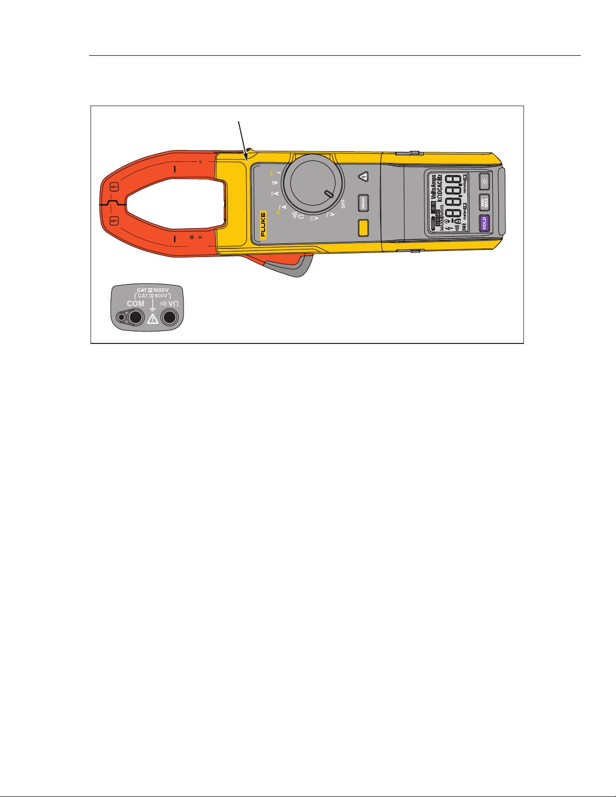
The Meter
Remote Display True-rms Clamp Meter
The Meter
Tactile Barrier
CAT
100 0 A
600V
1000V
CAT
iFlex
REMOTE DISPLAY
TRMS CLAMP METER
381
Figure 1. The Meter
Specifications
Electrical Specifications
AC Current Via Jaw
Range ..................................................... 999.9 A
Resolution ............................................... 0.1 A
Accuracy ................................................. 2 % ± 5 digits (10-100 Hz)
% ± 5 digits (100-500 Hz)
5
Crest Factor (50/60 Hz) .......................... 3 @ 500 A
2.5 @ 600 A
1.42 @1000 A
Add 2 % for C.F. > 2
ZERO
ghn02.eps
AC Current via iFlex
Range ..................................................... 999.9 A / 2500 A (45 Hz – 500 Hz)
Resolution ............................................... 0.1 A / 1 A
Accuracy ................................................. 3 % ±5 digits
Crest Factor (50/60Hz) ........................... 3.0 at 1100 A
2.5 at 1400 A
1.42 at 2500 A
Add 2 % for C.F. > 2
5
Find Quality Products Online at: [email protected]
www.GlobalTestSupply.com
Page 11
381
g
Calibration Manual
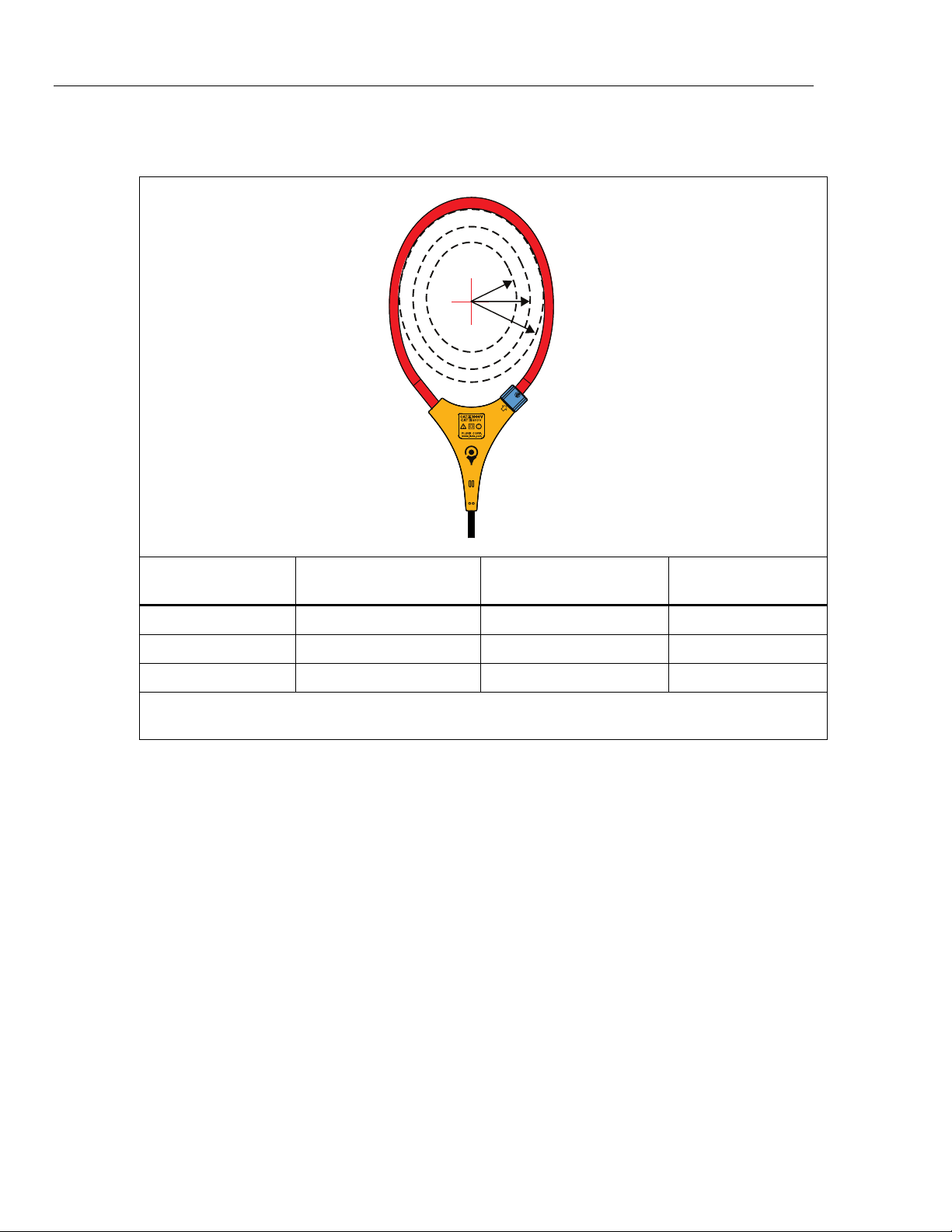
Position Sensitivity
Figure 2 shows the position sensitivity of the iFlex.
A
B
C
Distance from
Optimum
i2500-10 Flex i2500-18 Flex Error
A 0.5 in (12.7 mm) 1.4 in (35.6 mm) ± 0.5 %
B 0.8 in (20.3 mm) 2.0 in (50.8 mm) ± 1.0 %
C 1.4 in (35.6 mm) 2.5 in (63.5 mm) ± 2.0 %
Measurement uncertainty assumes centralized primary conductor at optimum position, no external
electrical or magnetic field, and within operating temperature range.
Figure 2. Position Sensitivity
DC Current
Range ..................................................... 999.9 A
Resolution ............................................... 0.1 A
Accuracy ................................................. 2 % ± 5 digits
AC Voltage
Range ..................................................... 600 V /1000 V
Resolution ............................................... 0.1 V / 1 V
Accuracy ................................................. 1.5 % ± 5 digits (20 to 500 Hz)
DC Voltage
Range ..................................................... 600.0 V /1000 V
Resolution ............................................... 0.1 V / 1 V
Accuracy ................................................. 1 % ± 5 digits
hn12.eps
Frequency – Via Jaw
Range ..................................................... 5.0 to 500.0 Hz
Resolution ............................................... 0.1 Hz
Accuracy ................................................. 0.5 % ± 5 digits
6
Find Quality Products Online at: [email protected]
www.GlobalTestSupply.com
Page 12

Remote Display True-rms Clamp Meter
Trigger Level ........................................... 5 to 10 Hz, ≥10 A
10 to 100 Hz, ≥5 A
100 to 500 Hz, ≥10 A
Frequency via iFlex
Range .................................................... 5.0 to 500.0 Hz
Resolution .............................................. 0.1 Hz
Accuracy ................................................ 0.5 % ± 5 digits
Trigger Level .......................................... 5 to 20 Hz, ≥ 25 A
20 to 100 Hz, ≥ 20 A
100 to 500 Hz, ≥ 25 A
Resistance
Range ..................................................... 600 Ω/6 kΩ/60 kΩ
Resolution ............................................... 0.1 Ω/1 Ω/10 Ω
Accuracy ................................................. 1 % ± 5 digits
Mechanical Specifications
Size (L x W x H) ..................................... 277 mm *88 mm * 43 mm (55 mm for remote unit)
Weight ..................................................... 350 g
Jaw Opening ........................................... 34 mm
iFlex Diameter ......................................... 7.5 mm
iFlex Cable Length
(head to electronics connector) .............. 1.8 m
Specifications
Environmental Specifications
Operating Temperature ........................... -10 °C to +50 °C
Storage Temperature .............................. -40 °C to +60 °C
Operating Humidity ................................. Non condensing (< 10 °C)
≤
90 % R
H (at 10 °C to 30 °C)
75 % R
≤
≤
(Without
Operating Altitude
Storage Altitude ...................................... 12,000 meters
EMI, RFI, EMC, RF ................................. EN 61326-1:2006, EN 61326-2-2:2006
Temperature Coefficients........................ Add 0.1 x specified accuracy for each degree C above
Wireless Frequency ................................ 2.4 GHz ISM Band 10 meter range
Safety Compliance .................................. ANSI/ISA S82.02.01:2004
Double Insulation Clearance ................... Per IEC 61010-2-032
Double Insulation Creepage ................... Per IEC 61010-1
Agency Approvals ...................................
................................... 2000 meters
ETSI EN 300 328 V1.7.1:2006
ETSI EN 300 489 V1.8.1:2008
FCC Part 15 Subpart C Sections 15.207, 15.209, 15.249 FCCID: T68-F381
RSS-210 IC:
28
CAN/CSA-C22.2 No. 61010-1-04
IEC/EN 61010-1:2001 to 1000V CAT III, 600V CAT IV.
P, ), , ®, Ã (KCC-CRM-T68-F381)
H (at 30 °C to 40 °C)
45 % R
H (at 40 °C to 50 °C)
Conden
°C
or below 18 °C
sation)
6627A-F381
7
Find Quality Products Online at: [email protected]
www.GlobalTestSupply.com
Page 13
381
Calibration Manual
Required Equipment
Calibrator 4.5-digit resolution Fluke 552xA Calibrator
Wired coil 50 turns 5500A/COIL
Test Probe for iFlex 2 mm to 4 mm Slim reach probe TP2, PN650892
Test Lead Test Lead w/retractable sheath 6358, PN1903307
Performance Tests
The equipment listed in Table 2 is required for performance tests and calibration
adjustment.
Table 2. Required Equipment
Equipment Required Characteristics Recommended Model
XWWarning
To prevent possible electrical shock, fire, or personal injury,
do not perform the performance test procedures unless the
Product is fully assembled.
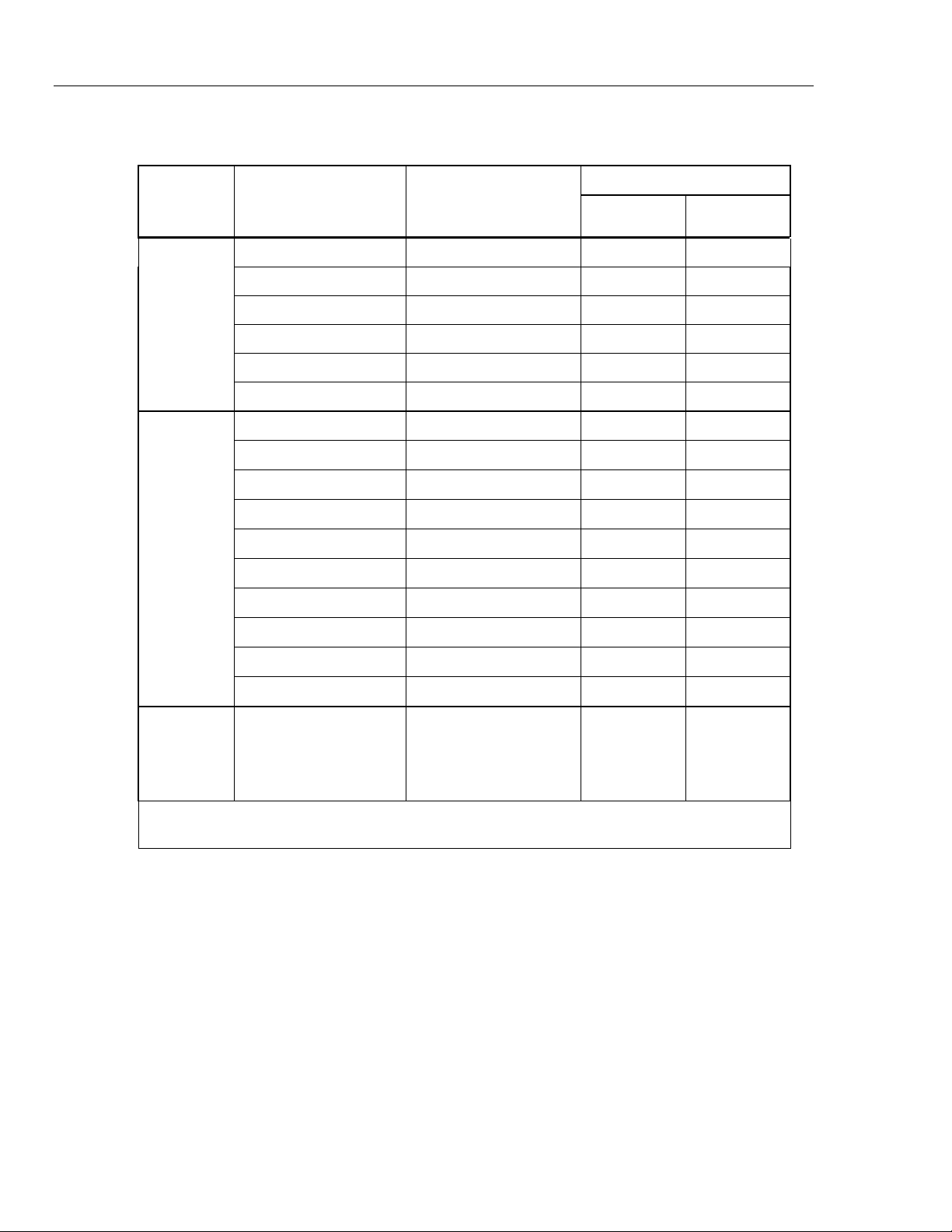
The following performance tests verify the complete operation of the Product and check
the accuracy of each function against the specifications of the Product. See Table 3. If the
Product fails any part of the test, calibration adjustment and/or repair is indicated. See
“Calibration Adjustment”. Table 3 shows the Performance tests for the product. Table 4
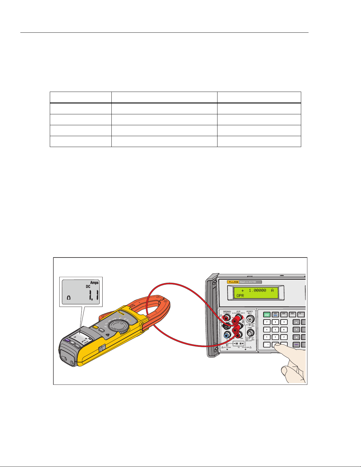
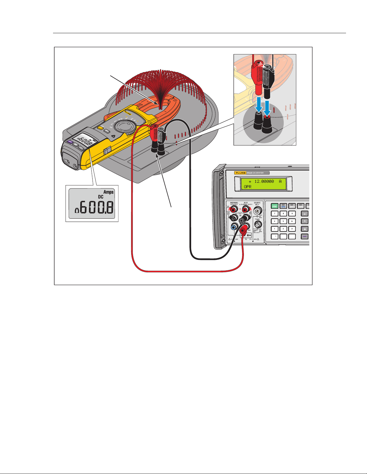
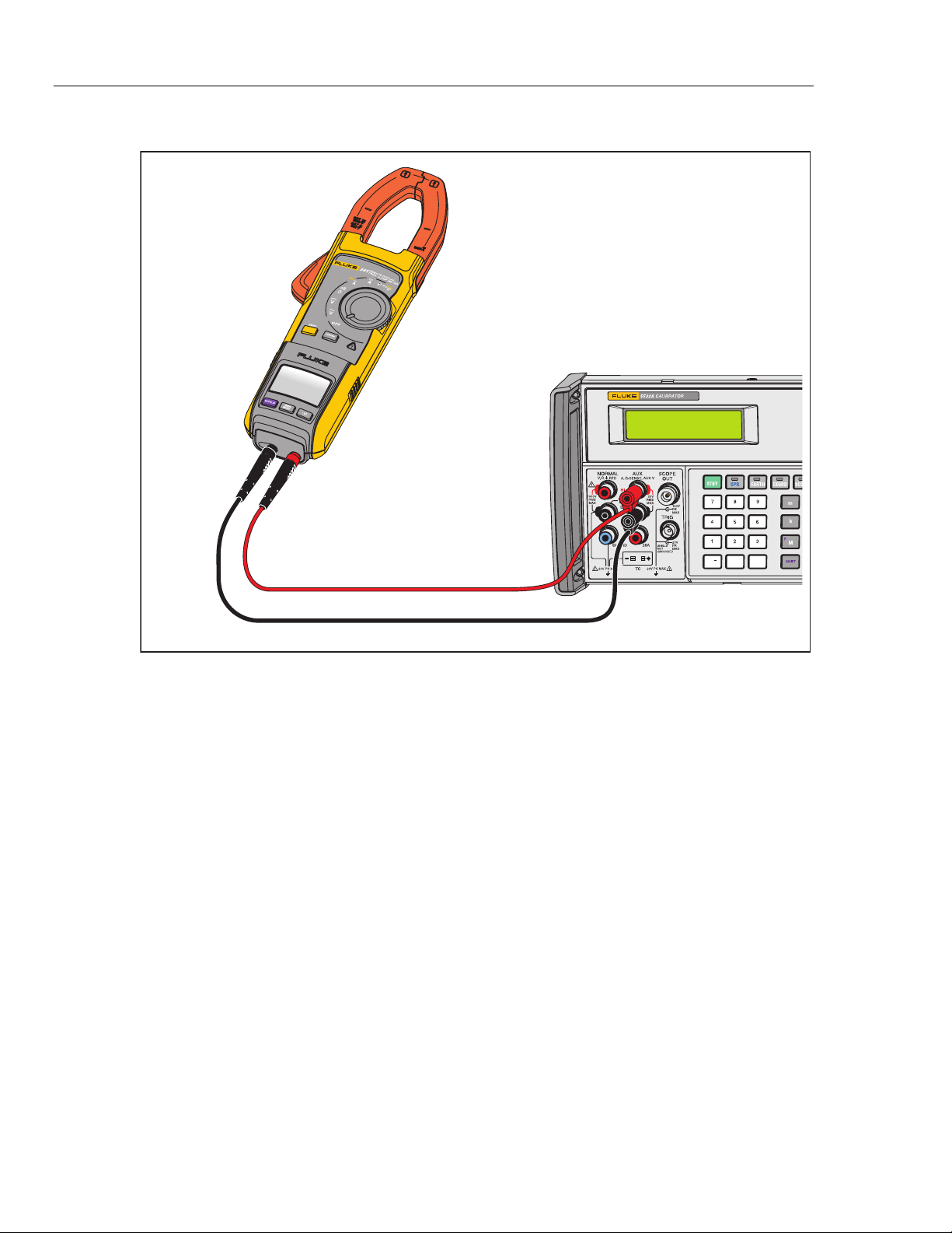
shows the Performance tests for the iFlex. Figures 3 and 4 show the performance test
connections for ac amps and dc amps. Figure 5 shows the performance test connections
for ac volts, dc volts, and frequency.
381
REMOTE DISPLAY
T
RMS
CLAMP METER
iFlex
+
•
/
0
Figure 3. Performance Test Connections for AC Amps and DC Amps
ghn10.eps
8
Find Quality Products Online at: [email protected]
www.GlobalTestSupply.com
Page 14
10
50-Turn Current Coil
Remote Display True-rms Clamp Meter
Performance Tests
Conductor
600V
1000A
CAT
381
REMOTE DISPLAY
T
R
MS CLAMP METER
iFlex
600V
1000A
5522A
Polarity is
Reversed
+
•
/
0
Figure 4. Performance Test Connections for AC Amps, DC Amps, and Frequency
ghn07.eps
9
Find Quality Products Online at: [email protected]
www.GlobalTestSupply.com
Page 15
381
Calibration Manual
5522A
+
/
0
Figure 5. Performance Test Connections for AC Voltage, DC Voltage, and Frequency
•
ghn15.eps
10
Find Quality Products Online at: [email protected]
www.GlobalTestSupply.com
Page 16
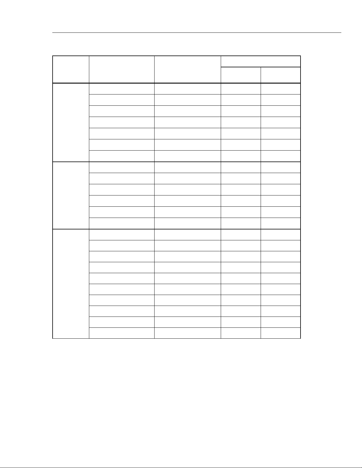
Table 3. Performance Tests
Remote Display True-rms Clamp Meter
Performance Tests
Test
(Switch
Position)
K
AC Volts
L
DC Volts
Nominal
20 V 20 V, 20 Hz 19.2 20.8
10 V 10 V, 50 Hz 9.4 10.7
600 V 600 V, 50Hz 590.5 609.5
1000 V 1000 V, 50Hz 980 1020
10 V 10 V, 500 Hz 9.4 10.7
600 V 600 V, 500 Hz 590.5 609.5
1000 V 1000 V, 500 Hz 980 1020
-1000 V -1000 V -1015 -985
-600 V -600 V -606.5 -593.5
-10 V -10 V -10.6 -9.4
10 V 10 V 9.4 10.6
600 V 600 V 593.5 606.5
1000 V 1000 V 985 1015
Calibrator Output
Value
UUT Meter Reading Limits
Low High
Ohms
0 e 0 e -0.5 0.5
10 e 10 e 9.4 10.6
100 e 100 e 98.5 101.5
590 e 590 e 583.6 596.4
1000 e 1000 e 985 1015
3000 e 3000 e 2965 3035
6000 e 6000 e 5935 6065
10 ke 10 ke 9.85 10.15
30 ke 30 ke 29.65 30.35
60 ke 60 ke 59.35 60.65
11
Find Quality Products Online at: [email protected]
www.GlobalTestSupply.com
Page 17
381
Calibration Manual
Table 3. Performance Tests (cont.)
Test
(Switch
Position)
AC Amps
(with 50-
Turn Coil)
DC Amps
(with 50Turn Coil)
Nominal
10 A 0.2 A, 50 Hz 9.3 10.7
100 A 2 A, 50 Hz 97.5 102.5
600 A 12 A, 50 Hz 587.5 612.5
900 A 18 A, 50 Hz 881.5 918.5
975 A 19.5 A, 50 Hz 955.0 995.0
10 A 0.2 A, 440 Hz 9.0 11.0
-975 A -19.5 A -995.0 -955.0
-600 A -12 A -612.5 -587.5
-100 A -2 A, -102.5 -97.5
-10 A -0.2 A -10.7 -9.3
0 A 0 A
10 A 0.2 A 9.3 10.7
100 A 2 A 97.5 102.5
Calibrator Output
Value
[1]
UUT Meter Reading Limits
Low High
-0.5 0.5
600 A 12 A 587.5 612.5
900 A 18 A 881.5 918.5
975 A 19.5 A 955.0 995.0
Frequency
(with 50Turn Coil)
[1] The 0 A dc test must be performed with a single wire connected from 552XA AUX HI to AUX
LO and the 381 clamped around the wire.
50 Hz 0.1 A, 50 Hz 49.3 50.8
12
Find Quality Products Online at: [email protected]
www.GlobalTestSupply.com
Page 18
Remote Display True-rms Clamp Meter
Performance Tests
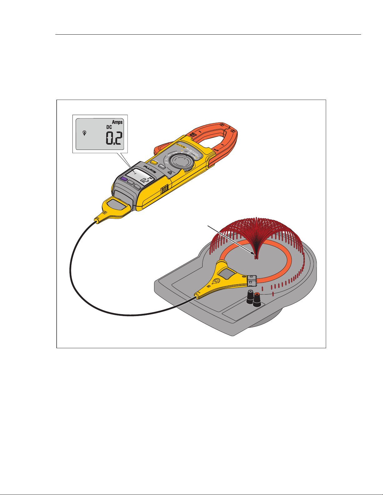
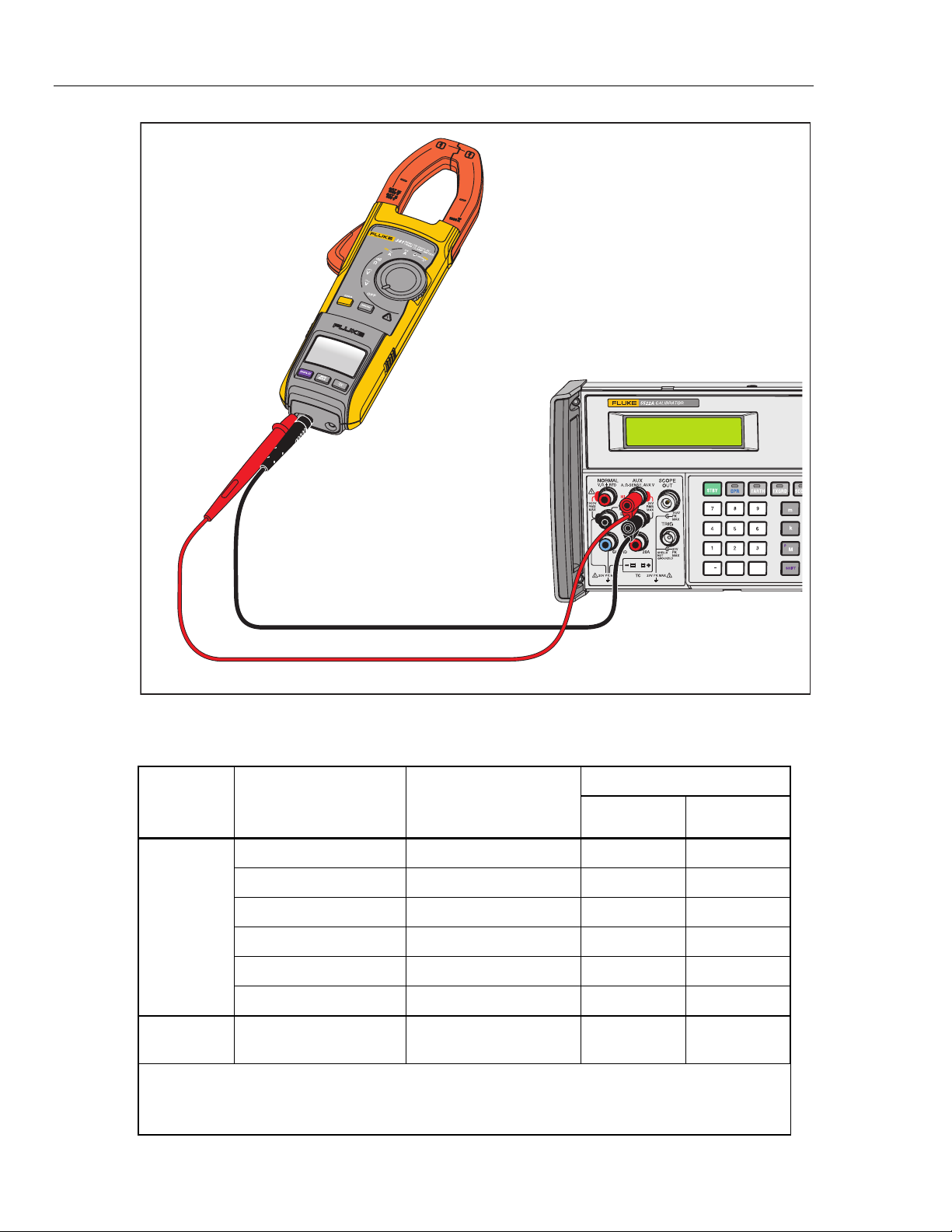
Performance tests for the iFlex are in Table 4. Connect the 5520A A ac output to the 50turn coil. Figures 6 and 7 show the performance test connections for the iFlex. For the
iFlex simulated tests you need the leads and probes listed in the required equipment list.
They are used to connect the calibrator output to the iFlex input. Calibrator Output HI
goes to the iFlex 2 mm jack (on the far left) and the Calibrator Output LO goes to the
black COM jack. See the notes in Table 4.
50-Turn Current Coil
Conductor
Figure 6. Performance Test Connections for the iFlex
ghn13.eps
13
Find Quality Products Online at: [email protected]
www.GlobalTestSupply.com
Page 19
381
Calibration Manual
5522A
Test
(Switch
Position)
AAC/R-coil
Figure 7. Current Test Simulated with Voltage
Table 4. iFlex Performance Tests
Nominal
10 A 0.2 A, 50 Hz
600 A 12 A, 50 Hz
995 A 19.9 A, 50 Hz
2500 A 75 mV, 50 Hz
10 A 0.2 A, 500 Hz
Calibrator Output
Value
[1]
[1]
[1]
[2]
[1]
2500 A 750 mV, 500 Hz
+
•
/
0
ghn14.eps
UUT Meter Reading Limits
Low High
9.2 10.8
581.5 618.5
964.6 1025.4
2420 2580
9.2 10.8
[2]
2420 2580
Freq./Rcoil
[1] Connect the 552XA AAC output to the 50-turn coil. Connect the iFlex coil from the 381 to the 50-Turn Coil.
See connections in Figure 6.
[2] Simulated by voltage. Connect the 552XA VAC output to the 381. See the connection in Figure 7.
50 Hz 50 Hz, 0.4 A
[1]
49.3 50.8
14
Find Quality Products Online at: [email protected]
www.GlobalTestSupply.com
Page 20

Calibration Adjustment
Calibration Password Operation Procedure
A password is required to access the Calibration adjustment section of the Product. This
section explains how this functionality works. To enter a password:
1. Push and turn the rotary switch to . The display shows “CAL”.
Remote Display True-rms Clamp Meter
Calibration Adjustment
2. Push to enter the password entry mode. The display shows “????
3. Enter the 4-di
digits:
git password. For this step, the keys
are mapped to the corresponding
- 1
- 2
- 3
- 4
- 5
• If you enter a incorrect password, push or . The display shows “????
and you can re-enter the password.
• If you enter t
push to c
4. Push to
5. Once the Product has entered calibration m
step num
ber. Push to confirm a calibration value.
he correct password, push to conti
hange the password. See Ch
enter calibration m
ode.
ode, push
nue calibration (step 5) or
ange the Password.
to show the calibration
”.
”
15
Find Quality Products Online at: [email protected]
www.GlobalTestSupply.com
Page 21

381
Calibration Manual
Change the Password
To change the password:
1. The display shows “----“.
2. Enter the 4-digit password. For this step, the keys
digits:
- 1
- 2
- 3
- 4
- 5
After all 4 digits are entered, the leading “-“ icon appears on the display.
3. Push to
4. After the new password is entered, the Product reboot
“F381” and then changes to the current
step during this procedure, turning rotary switch to OFF terminates the Calibration
At any
Password mode.
Two Special Passwords
The Default Password is 1234. It is used when the Product shows “CAL ERR”, which
means that the calibration parameter is corrupted. Entering the default password takes
you to the calibration mode. After the Product is calibrated, “CAL ERR” disappears.
The Master Password is 4132. If the password is forgotten, you can enter the Master
Password after “????” shows on the display. Then push and the password is restored
to the Default Password: 1234. The Master Password is protected, and you cannot
change the Calibration Password to this combination.
store the new password.
select
are mapped to the corresponding
s and the display briefly
ed function.
shows
16
Adjustment Procedure
The Product features a closed-case calibration procedure. To adjust Product calibration:
Turn the Product ON.
1.
2. Push while turning the Rotary
3. Push
4. Enter the Calibration Password.
5. Push
.
again to enter calibration mode.
Switch to
.
Find Quality Products Online at: [email protected]
www.GlobalTestSupply.com
Page 22

Remote Display True-rms Clamp Meter
Calibration Adjustment
6. Turn the Rotary Switch to the function you wish to calibrate. If you wish to adjust
Jaw balance, see Balance Adjustme
nt.
7. Push .
8. See Table 5 and appl
9. Push to confirm
10. When
If you enter t
you are finished with the calibration adjustment, push and then push
to confirm
the change.
he calibration mode but do not wish to save the data, simply turn the Product
OFF.
Balance Adjustment
1. Push to enter the balance calibration mode. The display shows “up
2. Place the upper part of the
3. Wait for the reading to settle.
4. Push to record the reading. T
5. Place the lower part of jaw close to coil.
6. Wait for the reading to settle.
7. Push to record the reading.
8. Repeat these
It can take multiple cycles
y the required inputs
the value and move
.
the next calibration point.
jaw close to coil.
he display shows “don
steps, until the display shows “End
Note
before the display shows “End”.
”.
”.
”.
9. Push
to exit balance adjustment.
17
Find Quality Products Online at: [email protected]
www.GlobalTestSupply.com
Page 23

381
Calibration Manual
Table 5. Adjustment Procedure
Test
(Switch
Position)
L
DC Volts
K
AC Volts
Ohms
AC Amps
With 50-turn
Coil
DC Amps
With 50-turn
Coil
iFlex
Current
Probe
Product
LCD
Reading
C-01 0 V dc
C-02 1000 V dc
C-03 600 V, 60 Hz
C-04 600 V, 150 Hz
C-05 600 V, 250 Hz
C-06 600 V, 350 Hz
C-07 600 V, 440 Hz
C-08 10 e
C-09 400 e
C-10 1 ke
C-11 6 ke
C-12 10 ke
C-13 25 ke
C-14 45 ke
C-15 60 ke
C-16 BALANCE (3 A, 60 Hz JAW A ac)
C-17 TEMPERATURE (Note: There is no input required.)
C-18 12 A, 60 Hz JAW A ac
C-19 3 A, 60 Hz JAW A ac
C-20 3 A, 150 Hz JAW A ac
C-21 3 A, 250 Hz JAW A ac
C-22 3 A, 350 Hz JAW A ac
C-23 3 A, 440 Hz JAW A ac
0 A JAW A dc (Note: The 0 A dc Calibration (C-24) must be performed
C-24
C-25 12 A ,JAW A dc
C-26 21.6 mV, 60 Hz; Simulates 600 A, 60 Hz A ac
C-27 5.4 mV, 150 Hz; Simulates 150 A, 150 Hz A ac
C-28 13.5 mV, 150 Hz; Simulates 150 A, 150 Hz A ac
C-29 22.5 mV, 250 Hz; Simulates 150 A, 250 Hz A ac
C-30 31.5 mV, 350 Hz Simulates 150 A, 350 Hz A ac
C-31 39.69 mV, 440 Hz; Simulates 150 A, 440 Hz A ac
with a single wire connected from 552XA AUX HI to AUX LO and UUT
clamped around the wire.)
Action
18
Find Quality Products Online at: [email protected]
www.GlobalTestSupply.com
Page 24

Maintenance
Clean the Product
WCaution
To prevent possible damage to the Product or to equipment
under test, do not use abrasive cleaners. They will damage the
case.
To clean the Product, use a cloth with a mild cleaning solution.
Battery Replacement
XW Warning
To prevent possible explosion, fire, or personal injury, Replace
the batteries when the low battery indicator ( or
) shows to prevent incorrect measurements.
WCaution
To prevent possible damage to the Product or to equipment
under test:
Remote Display True-rms Clamp Meter
Maintenance
• Remove batteries to prevent battery leakage
the Product if it is not used for an extended period.
• Be sure that the battery
leakage.
To change the batteries, s
1. Make sure the Product is
2. Turn the Product over to access the batte
3. Use a flat-h
the battery
4. Replace the t
5. Reattach the battery compartm
6. Tighten the b
ead screwdriver to loosen the battery compartm
compartm
hree AA batteries.
attery compartm
ee Figure 8:
ent door.
polarity is correct to prevent battery
OFF.
ry compartment door screw
ent door.
ent door screw.
and damage to
.
ent door screw and lift off
19
Find Quality Products Online at: [email protected]
www.GlobalTestSupply.com
Page 25

381
Calibration Manual
Figure 8. Changing the Batteries
User Replaceable Parts
User replaceable parts are listed in Table 6.
Table 6. User Replaceable Parts
Fluke Part
Number
2838018 Battery, AAA 1.5V 5
3625529 Battery Door - Display Module 1
3766406 Battery Door - Main Base 1
3766445 Remote Display 1
3752973 Soft Case 1
3538357 Users Manual 1
3782019 TL175 test leads 1
3798105 Fluke I2500-18 Rogowski coil 1
1670641 Alligator,2 mm jack, red boot 1
Description Qty
ghn03.eps
1670652 Alligator,2 mm jack, black boot 1
20
Find Quality Products Online at: [email protected]
www.GlobalTestSupply.com
 Loading...