

Page 1

Find Quality Products Online at: [email protected]
377/377 FC
www.GlobalTestSupply.com
January 2021
©2021 Fluke Corporation. All rights reserved.
All product names are trademarks of their respective companies.
378/378 FC
Clamp Meter
Users Manual
Page 2

Find Quality Products Online at: [email protected]
Each Fluke product is warranted to be free from defects in material and workmanship under normal use and service. The warranty period is three
years and begins on the date of shipment. Parts, product repairs, and services are warranted for 90 days. This warranty extends only to the
original buyer or end-user customer of a Fluke authorized reseller, and does not apply to fuses, disposable batteries, or to any product which, in
Fluke's opinion, has been misused, altered, neglected, contaminated, or damaged by accident or abnormal conditions of operation or handling.
Fluke warrants that software will operate substantially in accordance with its functional specifications for 90 days and that it has been properly
recorded on non-defective media. Fluke does not warrant that software will be error free or operate without interruption.
Fluke authorized resellers shall extend this warranty on new and unused products to end-user customers only but have no authori ty to extend a
greater or different warranty on behalf of Fluke. Warranty support is available only if product is purchased through a Fluke authorized sales outlet
or Buyer has paid the applicable international price. Fluke reserves the right to invoice Buyer for importation costs of repair/replacement parts
when product purchased in one country is submitted for repair in another country.
Fluke's warranty obligation is limited, at Fluke's option, to refund of the purchase price, free of charge repair, or replacement of a defective product
which is returned to a Fluke authorized service center within the warranty period.
To obtain warranty service, contact your nearest Fluke authorized service center to obtain return authorization information, then send the product
to that service center, with a description of the difficulty, postage and insurance prepaid (FOB Destination). Fluke assumes no risk for damage in
www.GlobalTestSupply.com
transit. Following warranty repair, the product will be returned to Buyer, transportation prepaid (FOB Destination). If Fluke determines that failure
was caused by neglect, misuse, contamination, alteration, accident, or abnormal condition of operation or handling, including overvoltage failures
caused by use outside the product’s specified rating, or normal wear and tear of mechanical components, Fluke will provide an estimate of repair
costs and obtain authorization before commencing the work. Following repair, the product will be returned to the Buyer transportation prepaid and
the Buyer will be billed for the repair and return transportation charges (FOB Shipping Point).
THIS WARRANTY IS BUYER'S SOLE AND EXCLUSIVE REMEDY AND IS IN LIEU OF ALL OTHER WARRANTIES, EXPRESS OR IMPLIED,
INCLUDING BUT NOT LIMITED TO ANY IMPLIED WARRANTY OF MERCHANTABILITY OR FITNESS FOR A PARTICULAR PURPOSE.
FLUKE SHALL NOT BE LIABLE FOR ANY SPECIAL, INDIRECT, INCIDENTAL OR CONSEQUENTIAL DAMAGES OR LOSSES, INCLUDING
LOSS OF DATA, ARISING FROM ANY CAUSE OR THEORY.
Since some countries or states do not allow limitation of the term of an implied warranty, or exclusion or limitation of incidental or consequential
damages, the limitations and exclusions of this warranty may not apply to every buyer. If any provision of this Warranty is held invalid or
unenforceable by a court or other decision-maker of competent jurisdiction, such holding will not affect the validity or enforceability of any other
provision.
LIMITED WARRANTY AND LIMITATION OF LIABILITY
11/99
Page 3

Find Quality Products Online at: [email protected]
Table of Contents
www.GlobalTestSupply.com
Introduction . . . . . . . . . . . . . . . . . . . . . . . . . . . . . . . . . . . . . . . . . . . . . . . . . . . . . . . . . . . . . . . . . . . . . . . . . . . . . . . . . . . . . . 1
Safety Information. . . . . . . . . . . . . . . . . . . . . . . . . . . . . . . . . . . . . . . . . . . . . . . . . . . . . . . . . . . . . . . . . . . . . . . . . . . . . . . . . 2
Specifications . . . . . . . . . . . . . . . . . . . . . . . . . . . . . . . . . . . . . . . . . . . . . . . . . . . . . . . . . . . . . . . . . . . . . . . . . . . . . . . . . . . . 2
Before You Start . . . . . . . . . . . . . . . . . . . . . . . . . . . . . . . . . . . . . . . . . . . . . . . . . . . . . . . . . . . . . . . . . . . . . . . . . . . . . . . . . . 3
Terms to Know. . . . . . . . . . . . . . . . . . . . . . . . . . . . . . . . . . . . . . . . . . . . . . . . . . . . . . . . . . . . . . . . . . . . . . . . . . . . . . . . 5
Fluke Connect™ (377 FC/378 FC) . . . . . . . . . . . . . . . . . . . . . . . . . . . . . . . . . . . . . . . . . . . . . . . . . . . . . . . . . . . . . . . . 5
Radio Frequency Data . . . . . . . . . . . . . . . . . . . . . . . . . . . . . . . . . . . . . . . . . . . . . . . . . . . . . . . . . . . . . . . . . . . . . . 5
Fluke Connect™ Mobile App . . . . . . . . . . . . . . . . . . . . . . . . . . . . . . . . . . . . . . . . . . . . . . . . . . . . . . . . . . . . . . . . . 5
Battery . . . . . . . . . . . . . . . . . . . . . . . . . . . . . . . . . . . . . . . . . . . . . . . . . . . . . . . . . . . . . . . . . . . . . . . . . . . . . . . . . . . . . . 6
Features/Controls . . . . . . . . . . . . . . . . . . . . . . . . . . . . . . . . . . . . . . . . . . . . . . . . . . . . . . . . . . . . . . . . . . . . . . . . . . . . . 7
Display. . . . . . . . . . . . . . . . . . . . . . . . . . . . . . . . . . . . . . . . . . . . . . . . . . . . . . . . . . . . . . . . . . . . . . . . . . . . . . . . . . . . . . 8
Power . . . . . . . . . . . . . . . . . . . . . . . . . . . . . . . . . . . . . . . . . . . . . . . . . . . . . . . . . . . . . . . . . . . . . . . . . . . . . . . . . . . . . . . . . . 9
Auto Power Off . . . . . . . . . . . . . . . . . . . . . . . . . . . . . . . . . . . . . . . . . . . . . . . . . . . . . . . . . . . . . . . . . . . . . . . . . . . . . . . 9
Backlight . . . . . . . . . . . . . . . . . . . . . . . . . . . . . . . . . . . . . . . . . . . . . . . . . . . . . . . . . . . . . . . . . . . . . . . . . . . . . . . . . . . . 9
Power-On Options. . . . . . . . . . . . . . . . . . . . . . . . . . . . . . . . . . . . . . . . . . . . . . . . . . . . . . . . . . . . . . . . . . . . . . . . . . . . 10
Basic Measurements. . . . . . . . . . . . . . . . . . . . . . . . . . . . . . . . . . . . . . . . . . . . . . . . . . . . . . . . . . . . . . . . . . . . . . . . . . . . . . 11
Hazardous Voltage Indicator . . . . . . . . . . . . . . . . . . . . . . . . . . . . . . . . . . . . . . . . . . . . . . . . . . . . . . . . . . . . . . . . . . . . 11
FieldSense™ Measurement . . . . . . . . . . . . . . . . . . . . . . . . . . . . . . . . . . . . . . . . . . . . . . . . . . . . . . . . . . . . . . . . . . . . 11
FieldSense AC Current, Voltage, and Frequency. . . . . . . . . . . . . . . . . . . . . . . . . . . . . . . . . . . . . . . . . . . . . . . . . 11
L1-L2-L3 . . . . . . . . . . . . . . . . . . . . . . . . . . . . . . . . . . . . . . . . . . . . . . . . . . . . . . . . . . . . . . . . . . . . . . . . . . . . . . . . 12
Power Quality Indicator (378/378 FC) . . . . . . . . . . . . . . . . . . . . . . . . . . . . . . . . . . . . . . . . . . . . . . . . . . . . . . . . . 13
Title Page
i
Page 4

377/377 FC/378/378 FC
Users Manual
Find Quality Products Online at: [email protected]
AC/DC Voltage Measurement with Test Leads . . . . . . . . . . . . . . . . . . . . . . . . . . . . . . . . . . . . . . . . . . . . . . . . . . . . . . 13
Resistance/Continuity . . . . . . . . . . . . . . . . . . . . . . . . . . . . . . . . . . . . . . . . . . . . . . . . . . . . . . . . . . . . . . . . . . . . . . . . . 13
Capacitance . . . . . . . . . . . . . . . . . . . . . . . . . . . . . . . . . . . . . . . . . . . . . . . . . . . . . . . . . . . . . . . . . . . . . . . . . . . . . . . . . 14
DC Current. . . . . . . . . . . . . . . . . . . . . . . . . . . . . . . . . . . . . . . . . . . . . . . . . . . . . . . . . . . . . . . . . . . . . . . . . . . . . . . . . . 14
iFlex Probe. . . . . . . . . . . . . . . . . . . . . . . . . . . . . . . . . . . . . . . . . . . . . . . . . . . . . . . . . . . . . . . . . . . . . . . . . . . . . . . . . . 14
Measurement Features. . . . . . . . . . . . . . . . . . . . . . . . . . . . . . . . . . . . . . . . . . . . . . . . . . . . . . . . . . . . . . . . . . . . . . . . . . . . 16
Display Hold. . . . . . . . . . . . . . . . . . . . . . . . . . . . . . . . . . . . . . . . . . . . . . . . . . . . . . . . . . . . . . . . . . . . . . . . . . . . . . . . . 16
MIN/MAX/AVG Measurements. . . . . . . . . . . . . . . . . . . . . . . . . . . . . . . . . . . . . . . . . . . . . . . . . . . . . . . . . . . . . . . . . . . 16
Inrush Current . . . . . . . . . . . . . . . . . . . . . . . . . . . . . . . . . . . . . . . . . . . . . . . . . . . . . . . . . . . . . . . . . . . . . . . . . . . . . . . 16
Data Logging (377 FC/378 FC) . . . . . . . . . . . . . . . . . . . . . . . . . . . . . . . . . . . . . . . . . . . . . . . . . . . . . . . . . . . . . . . . . . 17
Clear Memory (377 FC/378 FC). . . . . . . . . . . . . . . . . . . . . . . . . . . . . . . . . . . . . . . . . . . . . . . . . . . . . . . . . . . . . . . . . . 17
www.GlobalTestSupply.com
Firmware Update (377 FC/378 FC). . . . . . . . . . . . . . . . . . . . . . . . . . . . . . . . . . . . . . . . . . . . . . . . . . . . . . . . . . . . . . . . . . . 17
Firmware Version . . . . . . . . . . . . . . . . . . . . . . . . . . . . . . . . . . . . . . . . . . . . . . . . . . . . . . . . . . . . . . . . . . . . . . . . . . . . . . . . 17
Maintenance . . . . . . . . . . . . . . . . . . . . . . . . . . . . . . . . . . . . . . . . . . . . . . . . . . . . . . . . . . . . . . . . . . . . . . . . . . . . . . . . . . . . 18
How to Clean the Case . . . . . . . . . . . . . . . . . . . . . . . . . . . . . . . . . . . . . . . . . . . . . . . . . . . . . . . . . . . . . . . . . . . . . . . . 18
Environmental . . . . . . . . . . . . . . . . . . . . . . . . . . . . . . . . . . . . . . . . . . . . . . . . . . . . . . . . . . . . . . . . . . . . . . . . . . . . . . . 18
Service . . . . . . . . . . . . . . . . . . . . . . . . . . . . . . . . . . . . . . . . . . . . . . . . . . . . . . . . . . . . . . . . . . . . . . . . . . . . . . . . . . . . . 18
ii
Page 5
Find Quality Products Online at: [email protected]
Introduction
The Fluke 377, 377 FC, 378, and 378 FC Current Clamp (the
Clamp or Product) provides:
www.GlobalTestSupply.com
• display with two simultaneous measurements (current and
voltage)
• grounding with a single lead
• live measurements with no circuit downtime
• non-contact voltage measurement with Power Quality
Indicator
• wireless connectivity to smartphone for work-orders and
reporting integration with Fluke Connect™ app
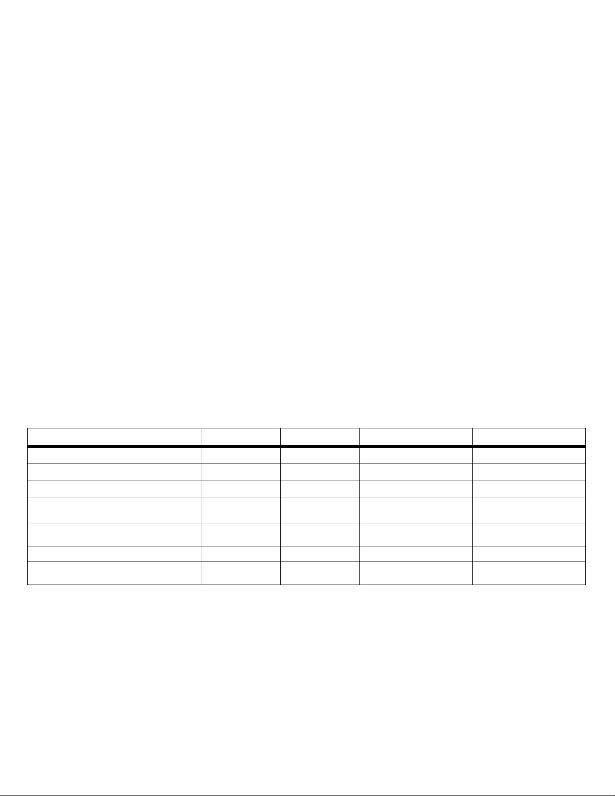
Model 377 378 377 FC 378 FC
BLE for Fluke Connect™ App
Power Quality Indicator
Phase Rotation
Sequential phase: non-contact voltage
measurement
Phase-to-phase voltage calculation
True RMS
The Clamp measures true-rms ac current and voltage, dc current
and voltage, inrush current, resistance, capacitance, frequency,
and dc millivolts.
The included iFlex (detachable, flexible current-probe) expands
the measurement range to 2500 A ac. The iFlex allows
measurements of awkward sized conductors and improved wire
access.
The illustrations in this manual show the 378 FC.
Table 1 is a list of features available for each model.
Table 1. Features by Model
••
••
Fluke Connect App Only Fluke Co nnect App Only
•• • •
•• • •
•• • •
Logging
••
1
Page 6
Find Quality Products Online at: [email protected]
Before You Start
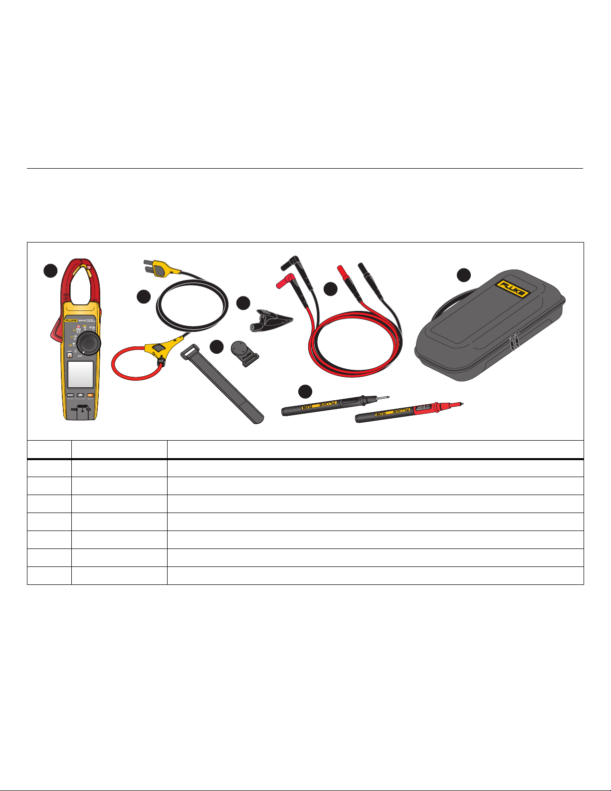
Table 2 is a list of items included with the Product. Use Table 3 to
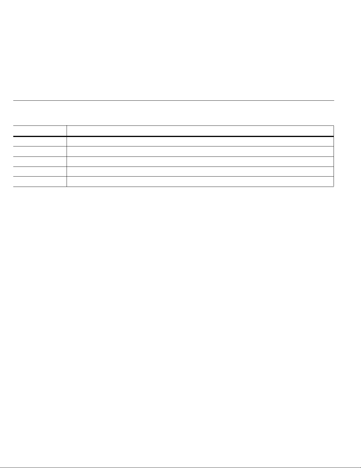
order additional accessories.
Clamp Meter
Before You Start
Table 2. Standard Equipment
1
2
4
5
7
www.GlobalTestSupply.com
3
6
Item Model Number Description
varies Clamp Meter
i2500-18 iFlex Flexible Current Probe 18 in (48 cm)
TPAK Hanging Kit
AC285 Alligator Clip (black)
TL224 Insulated Test Lead Set
TP175 Test Probe Set
37x Carry Case
3
Page 7
377/377 FC/378/378 FC
Users Manual
Find Quality Products Online at: [email protected]
Table 3. Accessories
Model Number Description
C550 Tool Bag
AC87 Heavy-Duty Bus Bar Clip Set (one pair: red and black)
AC89 Heavy-Duty Insulation Piercing Test Clip
TL27 Heavy Duty Test Lead Set
TL75 Hard Point Test Lead Set (one pair: red and black)
www.GlobalTestSupply.com
4
Page 8

Clamp Meter
Find Quality Products Online at: [email protected]
Before You Start
Terms to Know
Use this section to familiarize yourself with these terms that are
unique to this Product.
FieldSense™ Technology/Non-contact voltage (NCV)
Measurement. Voltage measurements by capacitive sensing
technology that completes galvanic isolation. This technology uses
capacitive sensors for measuring AC voltages through nongalvanic contact, coupled with a Hall Effect jaw that allows
simultaneous current measurements. It enables minimizing
voltage probes connections, therefore reducing hazardous
situations and saving setup-up time, and circuit or machine
www.GlobalTestSupply.com
downtime. Fluke-developed icon for FieldSense technology is U.
L1-L2-L3. L1, L2, and L3 (or Line 1, Line 2, and Line 3) is a
common naming convention for the wires in three-phase
alternating current (ac) systems. The Clamp features a sequential
line-to-ground measurement that results in a calculated line-to-line
voltage measurement. This voltage measurement is an indication
that the three-phase system is, or is not, working as expected.
Power Factor. Power factor (PF) is the ratio of working power,
measured in kilowatts (kW), to apparent power, measured in
kilovolt amperes (kVA). PF expresses the ratio of true power used
in a circuit to the apparent power delivered to the circuit.
Fluke Connect™App. Fluke Connect is a system that wirelessly
connects your Clamp with an app on your smartphone or tablet.
THD. The total harmonic distortion is a measurement of the
harmonic distortion present in a signal and is defined as the ratio
of the sum of the powers of all harmonic components to the power
of the fundamental frequency.
Fluke Connect™ (377 FC/378 FC)
Fluke Connect™ software (may not be available in all regions)
supports the Clamp to wirelessly connect to a mobile app. The app
shows the measurements and other data on your smartphone or
tablet display. You can share this data with your team and save
collected measurements and calculations to the Fluke Connect
Cloud.
Fluke Connect uses low-power 802.15.4 wireless radio technology
to connect the Clamp with an app on your smartphone or tablet.
The wireless radio does not cause interference with Clamp
measurements.
Radio Frequency Data
Note
Changes or modifications to the wireless 2.4 GHz
radio not expressly approved by Fluke Corporation
could void the user’s authority to operate the
equipment.
SIMPLIFIED EU DECLARATION OF CONFORMITY
Hereby, Fluke declares that the radio equipment contained in this
Product is in compliance with Directive 2014/53/EU. The full text of
the EU declaration is available
Fluke Connect™ Mobile App
The Fluke Connect™ app works with Apple and Android mobile
products. The app is available for download to your smart device
from the Apple App Store and Google Play.
To use the Fluke Connect app:
1. Open the Fluke Connect app on your device.
2. Turn on the Clamp.
3. Push F to activate the radio on the Clamp. E shows on the
display.
4. On your smartphone, go to Settings > Bluetooth.
5. Verify that Bluetooth is turned on.
6. Go to the Fluke Connect App and in the list of connected
Fluke tools, select 377 FC/378 FC.
You can now take, save, and share measurements with the
app.
5
Page 9
377/377 FC/378/378 FC
Users Manual
Find Quality Products Online at: [email protected]
Battery
XW Warning
To prevent personal injury and for safe operation
of the Product:
• The battery door must be closed and locked
before you operate the Product.
• Remove all probes, test leads, and accessories
before the battery door is opened.
• Replace the batteries when the low battery
www.GlobalTestSupply.com
indicator shows to prevent incorrect
measurements.
• When batteries are changed, ensure that the
calibration seal in the battery compartment is
not damaged. If damaged, the Product may not
be safe to use. Return the Product to Fluke for
replacement of the seal.
W Caution
To prevent damage to the battery:
• Repair the Product before use if the battery
leaks.
• Do not expose battery to heat sources or hightemperature environments such as an
unattended vehicle in the sun.
• Always operate in the specified temperature
range.
• Do not incinerate the Product and/or battery.
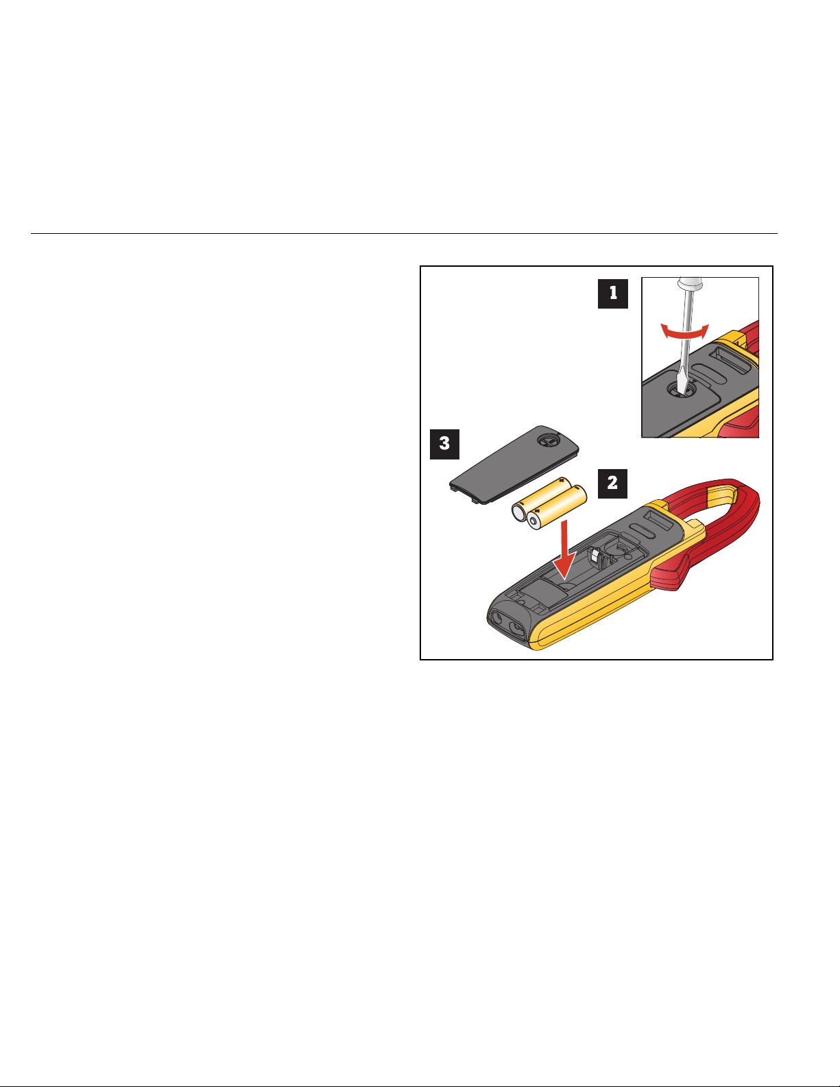
Figure 1. Batteries
AA
The Product ships with the batteries installed. To replace batteries,
see Figure 1.
6
Page 10
Find Quality Products Online at: [email protected]
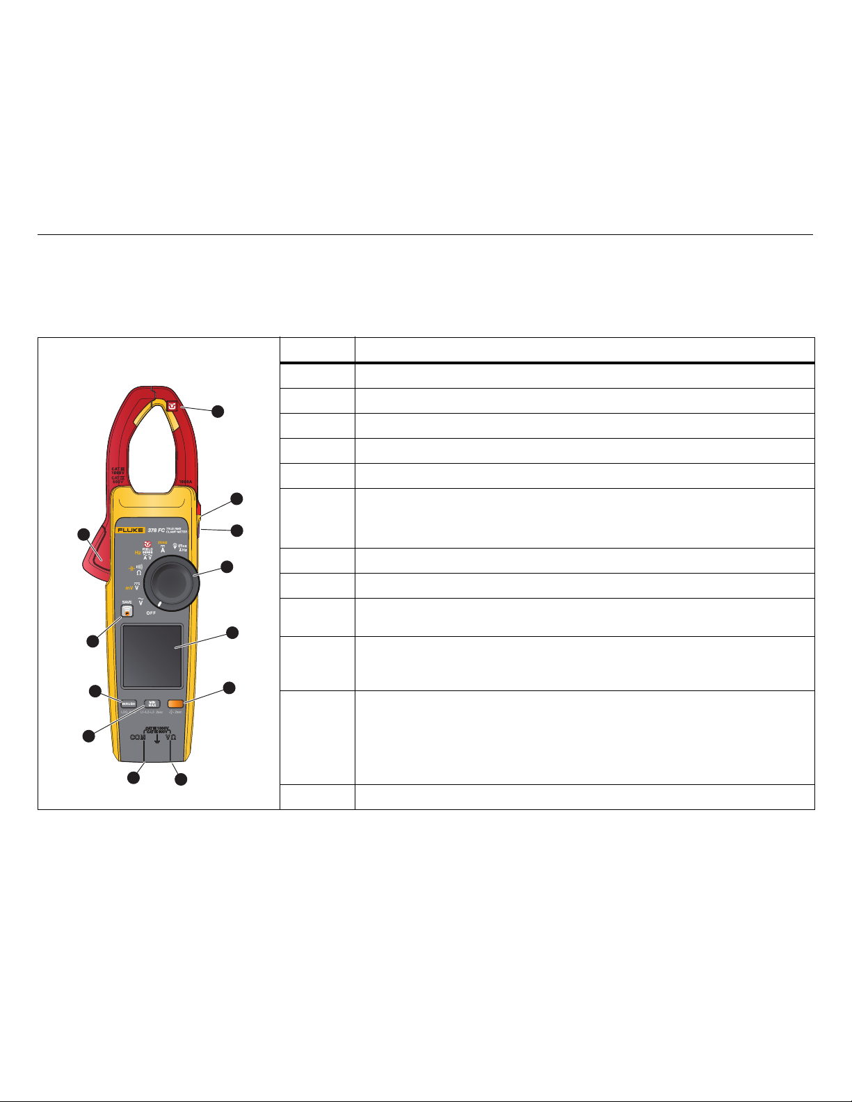
Features/Controls
Table 4 is a list of features and controls.
Clamp Meter
Before You Start
Table 4. Feature/Control Descriptions
Item Description
1
www.GlobalTestSupply.com
2
12
3
4
11
5
10
6
Jaw with FieldSense™ technology U
Tactile Barrier
Hold
Control Knob
Display
377/378: @ turn on/turn off the backlight.
377 FC/378 FC: B extends the function selection to yellow items on the control
knob. Push >2 s. to turn on/turn off the backlight.
Volts/Ohm input terminal
Common terminal
Min/Max/Avg for current, voltage, and frequency measurement functions.
Push >2 s. to turn on/turn off the L1-L2-L3 measurement function.
INRUSH: push to enter inrush mode. Push a second time to exit inrush mode.
Integration time is 100 ms.
Push >2 s. to start data logging function with the Fluke Connect mobile app.
377/378: B extends the function selection to yellow items on the control knob.
377 FC/378 FC:
9
when paired with the Fluke Connect mobile phone app. When on, push F to
save a measurement to the Fluke Connect mobile app. Push
8
7
the Fluke Connect feature.
Jaw release
F turn on the Fluke Connect feature. F turns blue and flashes
F >2 s. to turn off
7
Page 11
377/377 FC/378/378 FC
Users Manual
Find Quality Products Online at: [email protected]
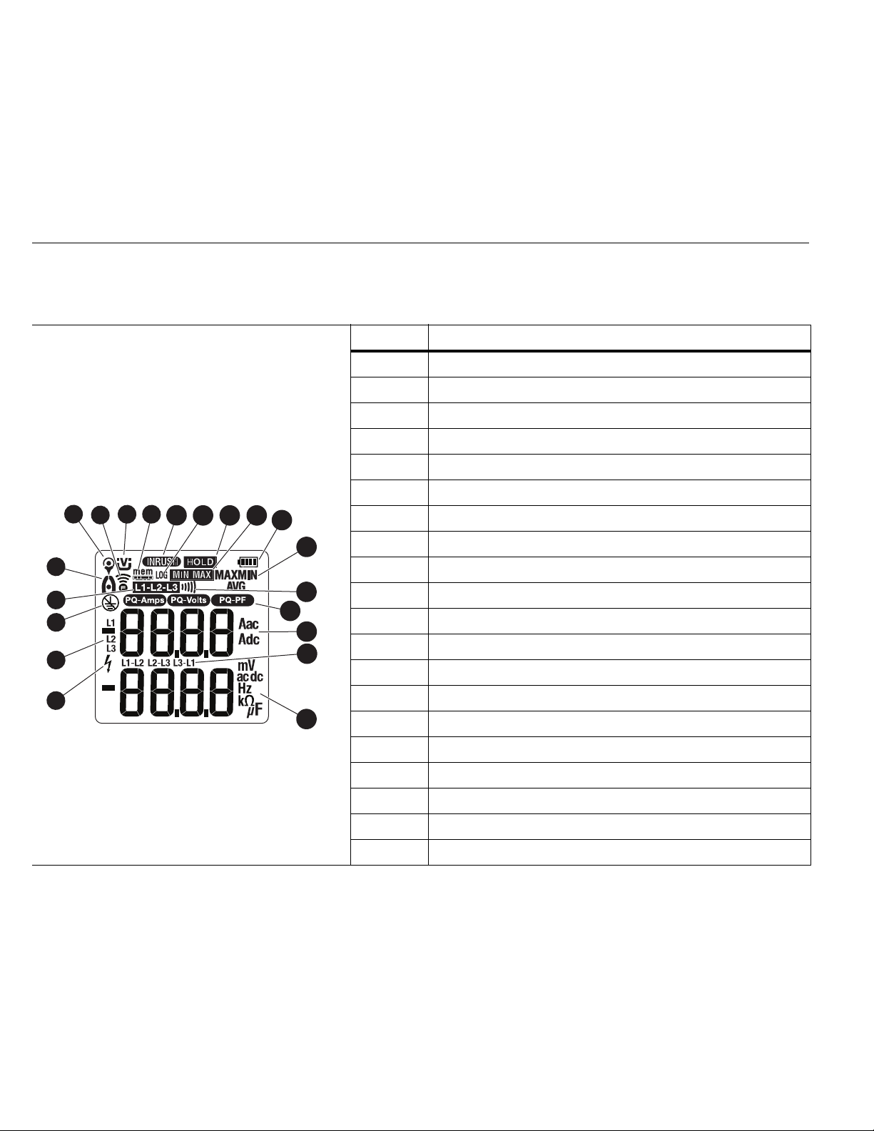
Display
Table 5 is a list of the display annunciators.
Table 5. Display
Item Description
www.GlobalTestSupply.com
6
7
5
4
3
2
9
8
10
11
12
13
14
15
16
17
18
19
1
20
Clamp senses a voltage ±30 V or a voltage overload (OL)
L1, L2, L3 mode is active
FieldSense™ measurement requires a ground connection
Line-to-line measurement
Jaw measurement
iFlex measurement
Fluke Connect feature is on
FieldSense™ measurement
Remaining memory (377 FC/378 FC)
Inrush measurement
Log mode is active (377 FC/378 FC)
Hold mode is active
MinMax mode is active
Battery status
Min, Max, or Avg measurement indication
Continuity indication
Power Quality indication: PQR
Current measurement
Line-to-line calculation
Voltage/resistance/capacitance/frequency measurement
8
Page 12

Clamp Meter
Find Quality Products Online at: [email protected]
Power
Power
Two AA batteries supply power to the Clamp:
• To turn on the Clamp, rotate the control knob to a function.
• To turn off the Clamp, rotate the control knob to OFF.
Auto Power Off
The Clamp automatically powers off after 20 minutes of no use. If
the Clamp automatically powers off, turn the control knob to OFF
and then to a function to resume operation.
To disable auto power off, see Power-On Options.
www.GlobalTestSupply.com
Auto power off is always disabled when you use the
Min/Max/Avg function.
Note
Backlight
The display on the Clamp includes a backlight that improves the
readability in dim work areas.
FC models:
• Hold B for >2 seconds to turn on the backlight.
• Hold B for >2 seconds to turn off the backlight.
Non-FC models:
•Push @ to toggle on/toggle off the backlight.
The backlight has an auto off feature that turns off the backlight
after 2 minutes of no use. To disable the auto off backlight feature,
see Power-On Options.
9
Page 13
377/377 FC/378/378 FC
Users Manual
Find Quality Products Online at: [email protected]
Power-On Options
Power-on options allow you to customize the controls:
• Turn off/turn on audible beeper
• Turn off/turn on auto backlig h t
• Turn on/turn off auto pow er sh utoff
• Clear Logging Memory
• Set PQ Sensitivity Level
To select a power-on option:
1. Turn off the Clamp.
www.GlobalTestSupply.com
2. Push and hold
The Clamp goes into the option mode.
Anytime you release
mode but retains any changes to the settings.
3. Push
B to go through the options.
e as you turn the control knob to V.
Note
e the Clamp exits the option
4. Push
Beeper Enabled
Beeper Disabled
Auto Backlight On
(Backlight turns off after 2 minutes of no use)
Auto Backlight Off
(Backlight stays on)
Auto Power On
(Clamp powers off after 20 minutes of no use)
Auto Power Off
(Auto Power Off is disabled)
Clear Logging Memory
PQ Sensitivity
5. Release
M to change a setting.
Option Display
e to exit the options mode.
All power-on options are canceled when you turn off the
Clamp with the exception of PQ Sensitivity setting.
bEEP On
bEEP OFF
8CLt On
8CLt OFF
AUtO On
AUtO OFF
CLr
LEU HI
LEU nmEd
LEU L0
10
Page 14
Clamp Meter
Find Quality Products Online at: [email protected]
Basic Measurements
Basic Measurements
XW Warning
To prevent possible electrical shock, fire, or
personal injury:
• Hold the Product behind the tactile barrier.
• Do not measure current while the test leads are
in the input jacks.
Note
Exposure to severe mechanical shock may cause the
readings of the Product to not meet the specifications.
www.GlobalTestSupply.com
If the published accuracy is required, the Product
should be calibrated to verify proper operation after
such an event.
Hazardous Voltage Indicator
When the Clamp senses a voltage ±30 V or a voltage overload
Z shows on the display to tell you a hazardous voltage is at
(OL),
the Clamp input.
FieldSense™ Measurement
FieldSense measurement, or non-contact voltage (NCV)
measurement, is ac voltage, current, and frequency measurement
with no electrical contact to live voltage. The Clamp display shows
the voltage and current measurements at the same time.
Note
All FieldSense measurements require a ground lead
connection.
FieldSense AC Current, Voltage, and Frequency
To make the measurement:
1. Insert the ground lead into the COM input and attach the
alligator clip to ground.
2. Rotate the control knob to U.
The display shows the
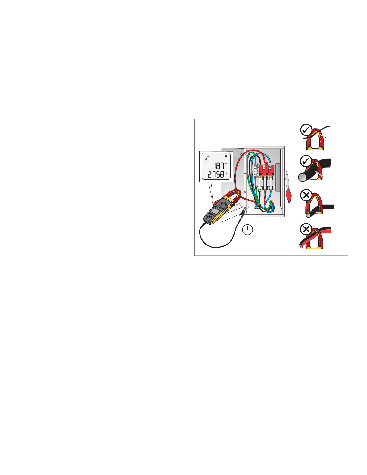
3. Use the jaw release to open the jaw and position the Clamp
around the conductor. Close the jaw and make sure the wire
position is correct. See Figure 2.
U icon.
Figure 2. Wire Placement
3.3 mm Ø
L1 L2 L3
34 mm Ø
The display shows
from the jaw. When the current measurement is <0.5 A, the
center dot in the icon flashes. For current measurements
>0.5 A, the center dot in the icon is steady. The Aac display
shows
- - - when a measurement is <1 A.
Use
B to toggle on/toggle off the Amps Hz function
shown in yellow at the control knob position.
FieldSense technology is not intended to measure the
output of a variable-frequency drive (VFD) motor
controller. Use the
this application.
C to indicate that the measurement is
Note
V or Kcontrol knob position for
11
Page 15

377/377 FC/378/378 FC
Users Manual
Find Quality Products Online at: [email protected]
L1-L2-L3
Three-phase alternating current (ac) systems are universally used
to distribute electrical power and to supply electricity directly to
high-power equipment. Use the Clamp to make sequential
line-to-ground measurements that result in calculated line-to-line
voltage measurements. These voltage measurements are an
indication that the three-phase system is, or is not, working as
expected.
When you use the Fluke Connect mobile app, the Clamp also
indicates the phase rotation as 1-2-3 or 3-2-1 in the three-phase
system.
www.GlobalTestSupply.com
To setup:
1. Turn the control knob to U.
2. Connect the Clamp to ground with the ground lead.
3. Push M for >2 seconds. The Clamp is in the line-to-line
mode and
To test:
1. Position the Clamp jaw around the first conductor.
Wait for the measurement on the display to settle. You will
hear a beep and
2. Move the Clamp jaw to the second conductor within
10 seconds.
Wait for the measurement on the display to settle. You will
hear a beep and
3. Move the Clamp jaw to the next conductor within 10 seconds.
Wait for the measurement on the display to settle. You will
hear a beep and z shows on the display.
x-y-z shows on the display.
x shows on the display.
y shows on the display.
When the
calculate the total voltage between each pair of conductors:
1. Push
2. Push
3. Push
While in the line-to-line mode, you can review each line-to-ground
measurement:
1. Push M again to show the L1 measurement.
2. Push
3. Push
To review L1-L2-L3 measurements, continue to push
scroll through the measurements.
To exit the line-to-line mode, push
x-y-z measurements are complete, use the Clamp to
M. The displays shows the total voltage between
L1 and L2.
M again to show the total voltage between
L2 and L3.
M again to show the total voltage between
L3 and L1.
M again to show the L2 measurement.
M again to show the L3 measurement.
M and
M for >2 seconds.
12
Page 16
Clamp Meter
Find Quality Products Online at: [email protected]
Basic Measurements
Power Quality Indicator (378/378 FC)
The Power Quality indicator shows that the ratio of the real power
compared to the apparent power or harmonic distortion is outside
the optimal range.
To setup:
1. Turn the control knob to U.
2. Connect the Clamp to ground with the ground lead.
If the total harmonic distortion or the power factor is outside
the optimal range, the related indicator shows on the display:
www.GlobalTestSupply.com
P
Q
R
Fluke Connect software supports the Power Quality indicator.
The Power Quality indicator sensitivity is adjustable:
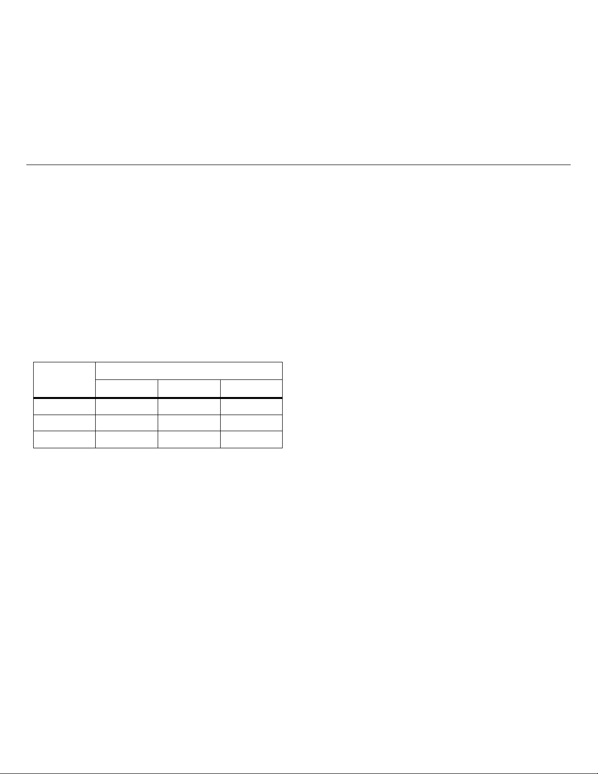
Sensitivity
Function
High Medium Low
PQ-Amps 10 % THD 25 % THD 50 % THD
PQ-Volts 8 % THD 10 % THD 15 % THD
PQ-PF 0.9 0.75 0.6
For information about how to set the sensitivity, see Power-On
Options.
AC/DC Voltage Measurement with Test Leads
To measure ac or dc voltage:
1. Turn control knob to
2. Connect the black test lead to the COM terminal and the red
test lead to the
3. Touch the probes to the test points of the circuit.
The display shows the measurement.
B to toggle on/toggle off the mV function
Use
shown in yellow at the control knob position.
V or N.
VX terminal.
Note
Resistance/Continuity
To measure resistance or continuity:
1. Turn the control knob to
2. Remove power from the circuit to test.
3. Connect the black test lead to the COM terminal and the red
test lead to the VX terminal.
4. Touch the probes to the test points of the circuit.
The display shows the measurement.
If the resistance is <30 Ω, the beeper sounds continuously to
indicate continuity. If the display shows OL, the circuit is open.
To disable the beeper, see Power-On Options.
D.
13
Page 17

377/377 FC/378/378 FC
Users Manual
Find Quality Products Online at: [email protected]
Capacitance
The Clamp determines capacitance by charging a capacitor with a
known current, measuring the resulting voltage, then calculating
the capacitance.
Note
A good capacitor stores an electrical charge and may
remain energized after power is removed. Before you
touch the capacitor or make a measurement, turn all
power OFF, use the Clamp to confirm that power is
OFF, and carefully discharge the capacitor by
connecting a resistor across the leads. Be sure to wear
www.GlobalTestSupply.com
appropriate personal protective equipment.
To test capacitance:
1. Turn the control knob to
2. Push
3. Remove the capacitor from the circuit and discharge the
4. Connect the black test lead to the COM terminal and the red
5. Touch the probes to the capacitor leads.
B to shift to the t function.
capacitor.
test lead to the VX terminal.
The display shows the measurement.
OL indicates the capacitor is faulty or the capacitance value is
higher then the measurement range. diSc indicates the
capacitor does not properly discharge.
D.
DC Current
To measure dc current:
1. Turn control knob to Y.
2. Push
B to compensate for outside influences.
The display shows
from the jaw. When the current measurement is <0.5 A, the
center dot in the icon flashes. For current measurements
>0.5 A, the center dot in the icon is steady.
C to indicate that the measurement is
iFlex Probe
XW Warning
To avoid electrical shock, do not apply or remove
from live hazardous conductors.
The high-performance AC Flexible Current Probe uses the
Rogowski principle for accurate, non-intrusive measurement of
sinusoidal, pulsed, and other complex waveforms. The flexible and
lightweight measuring head allows quick and easy installation in
hard-to-reach areas and works well with large conductors.
To use the iFlex Probe:
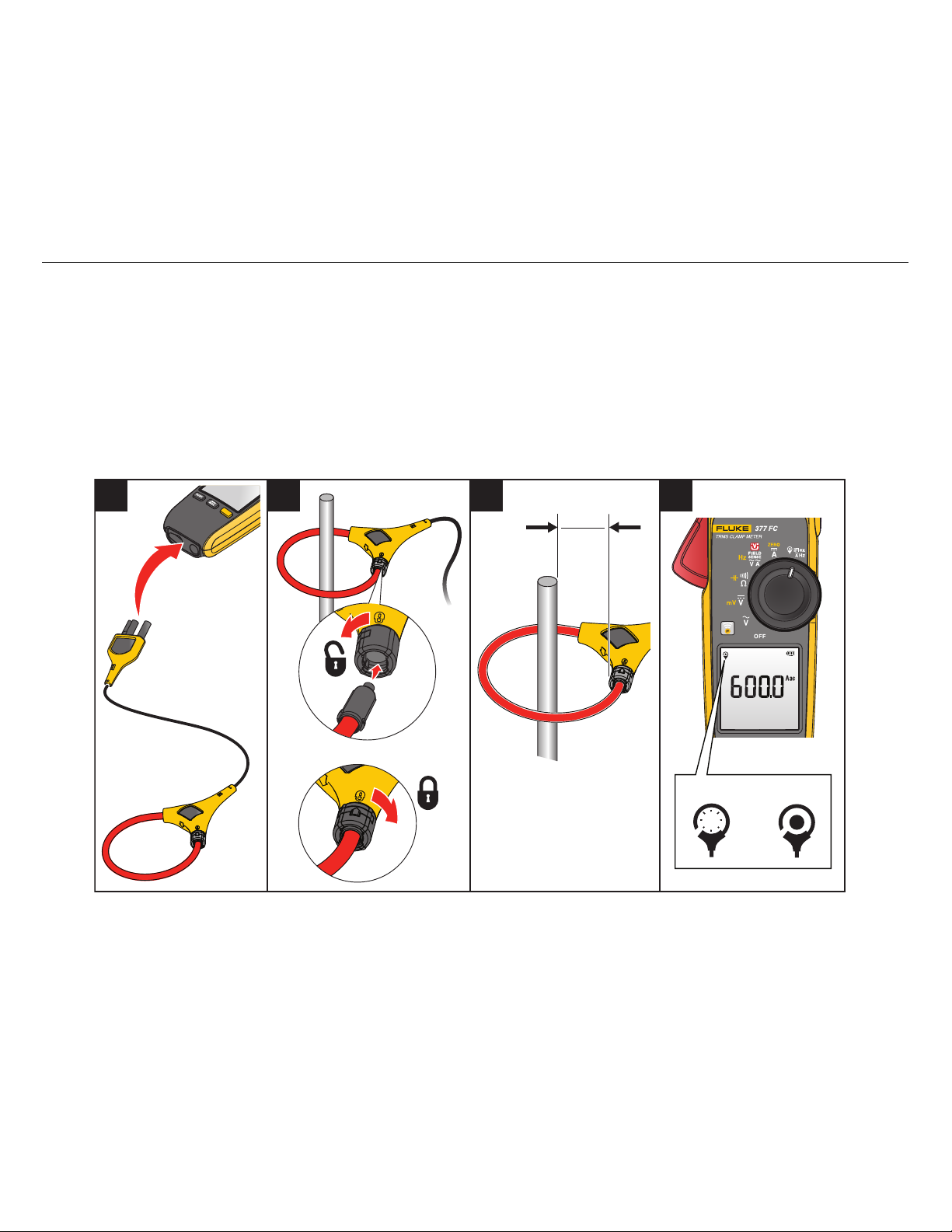
1. Connect the iFlex Probe to the Clamp. See Figure 3.
2. Connect the flexible part of the iFlex Probe around the
conductor. If you open the end of the iFlex Probe to make the
connection, make sure that you close and latch the coupling.
See the detail in Figure 3. You should be able to hear and feel
the lock snap into place.
Note
When you measure current, center the conductor in
the iFlex Probe. Avoid measurements close to other
current-carrying conductors.
14
Page 18
Clamp Meter
<0.5 A
>0.5 A
1 2 3 4
>2.5 cm
>1 in
Find Quality Products Online at: [email protected]
Basic Measurements
3. Keep the probe coupling >2.5 cm (1 inch) away from the
conductor.
4. Turn the control knob to
The display shows J to indicate that the measurements are
from the iFlex Probe. When the current measurement is
<0.5 A, the center dot in the icon flashes. For current
measurements >0.5 A, the center dot is steady.
The display shows the measurement.
www.GlobalTestSupply.com
K.
If the iFlex Probe does not work as expected:
• Make sure that the coupling system is connected and closed
correctly or look for any damage. If any foreign material is
present, the coupling system will not close properly.
• Inspect the cable between the iFlex Probe and the Clamp for
any damage.
• Check that the control knob is in the correct position
Figure 3. iFlex Probe Setup
K.
15
Page 19

377/377 FC/378/378 FC
Users Manual
Find Quality Products Online at: [email protected]
Measurement Features
This section is about the Clamp features you can use for
measurements.
XW Warning
To prevent possible electrical shock, fire, or
personal injury:
• Do not use the HOLD function to measure
unknown potentials. When HOLD is turned on,
the display does not change when a different
www.GlobalTestSupply.com
Display Hold
To capture and hold the display reading, push e. The display
freezes and blinks . The Clamp periodically beeps to remind
you that the measurement is not live. When in HOLD mode, if the
Clamp senses a voltage ±30 V or a voltage overload (OL),
on the display to tell you a hazardous voltage is at the Clamp input.
When in HOLD mode, push
with live readings.
potential is measured.
• Disconnect power and discharge all highvoltage capacitors before you measure
resistance, continuity, c ap ac itance, or a diode
junction.
Z shows
e again to resume normal operation
MIN/MAX/AVG Measurements
Min Max Avg mode captures the minimum, maximum, and
average readings of a given output signal over an extended time.
The Clamp beeps when it senses a new high value or new low
value.
This function works in current, voltage, and frequency modes:
1. Push
2. Continue to push
3. To exit Min/Max/Avg mode, push and hold
M to enter the Min/Max/Avg mode.
The maximum reading shows on the display.
M to select between the maximum,
minimum, average, and live readings.
The cycle continues each time you push
M.
M for >2 s.
Note
Auto Power Off is always disabled when you use the
Min Max Avg function.
Inrush Current
Inrush Current is surge current that occurs when an electrical
device is first powered on. The Clamp can capture this surge
current reading. Current spikes from motor drives are one example
of such an event. The Inrush function takes samples over a
100 ms period and calculates the starting current envelope.
To measure inrush current:
1. Select the measurement function (ac current, dc current, or
iFlex ac current).
2. Center the Jaw or iFlex Probe around the live wire on the
device.
3. Push
I.
Dashes show on the display until the Clamp detects the inrush
current. When the inrush current is detected, the
measurement shows on the display.
16
Page 20

Find Quality Products Online at: [email protected]
Firmware Update (377 FC/378 FC)
Clamp Meter
Data Logging (377 FC/378 FC)
The Fluke Connect™ app enables you to log the data
measurements. This app shows measurements from the
connected Clamp on your smartphone or tablet display. The app
also saves the measurements to the Fluke Connect Cloud™
storage and shares the information with your team.
Note
The logging interval is set in the Fluke Connect app.
Logging is not available for the inrush and line-to-line
measurement modes.
www.GlobalTestSupply.com
To log measurements:
1. On the Clamp, push
The memory icon indicates how much memory is available.
2. On the Clamp, push
I for >2 s.
I for >2 s to stop logging.
Clear Memory (377 FC/378 FC)
See Power-On Options.
Firmware Update (377 FC/378 FC)
Firmware updates are available for Clamps that have the
Fluke Connect™ feature. The Fluke Connect mobile app shows a
notification if a firmware update is available when the unit is
connected to the app.
To update:
1. Make sure the Product has at least 50 % battery power
available.
2. Make sure you download all the logged data before you
update the firmware.
3. In the app, tap Update to start the firmware update to the
Product.
Firmware Version
The firmware version for the Clamp is found in the Maintenance
Mode.
To enter Maintenance Mode:
1. Turn off the Clamp.
2. Push and hold
The Clamp goes into the option mode.
3. Push B until nmAt nm0d shows on the display.
4. Push
5. Release e.
6. Press
M.
All LCD segments turn on.
All LCD segments continue to show on the display.
e again to show the firmware version.
e as you turn the control knob to V.
17
Page 21
377/377 FC/378/378 FC
Users Manual
Find Quality Products Online at: [email protected]
Maintenance
The Product does not require routine maintenance.
XW Warning
To prevent possible electrical shock, fire, or
personal injury:
• Remove the input signals before yo u cl ean the
Product.
• Repair the Product before use if the battery
leaks. Battery leakage may create a shock
www.GlobalTestSupply.com
How to Clean the Case
Wipe the case with a damp cloth and mild detergent.
Environmental
This Product has electronic printed circuit boards. These
components must be disposed of specifically when the Product is
at the end of its use.
The manufacturer offers to take back the Product from the
customer to ensure that the Product is disposed of in an
hazard or damage the Product.
• Use only specified replacement parts.
• Have an approved technician repair the Product.
• Remove the batteries if the Product is not used
for an extended period of time, or if stored in
temperatures above 50 °C. If the batteries are
not removed, battery leakage may result.
W Caution
Do not use abrasives, isopropyl alcohol, or
solvents to clean the case or lens/window.
Service
An authorized Fluke Calibration service center should service the
Product at two-year intervals to maintain optimum performance.
Contact your equipment distributor or authorized Fluke Calibration
Service Center for any equipment performance failure or to
schedule regular maintenance service.
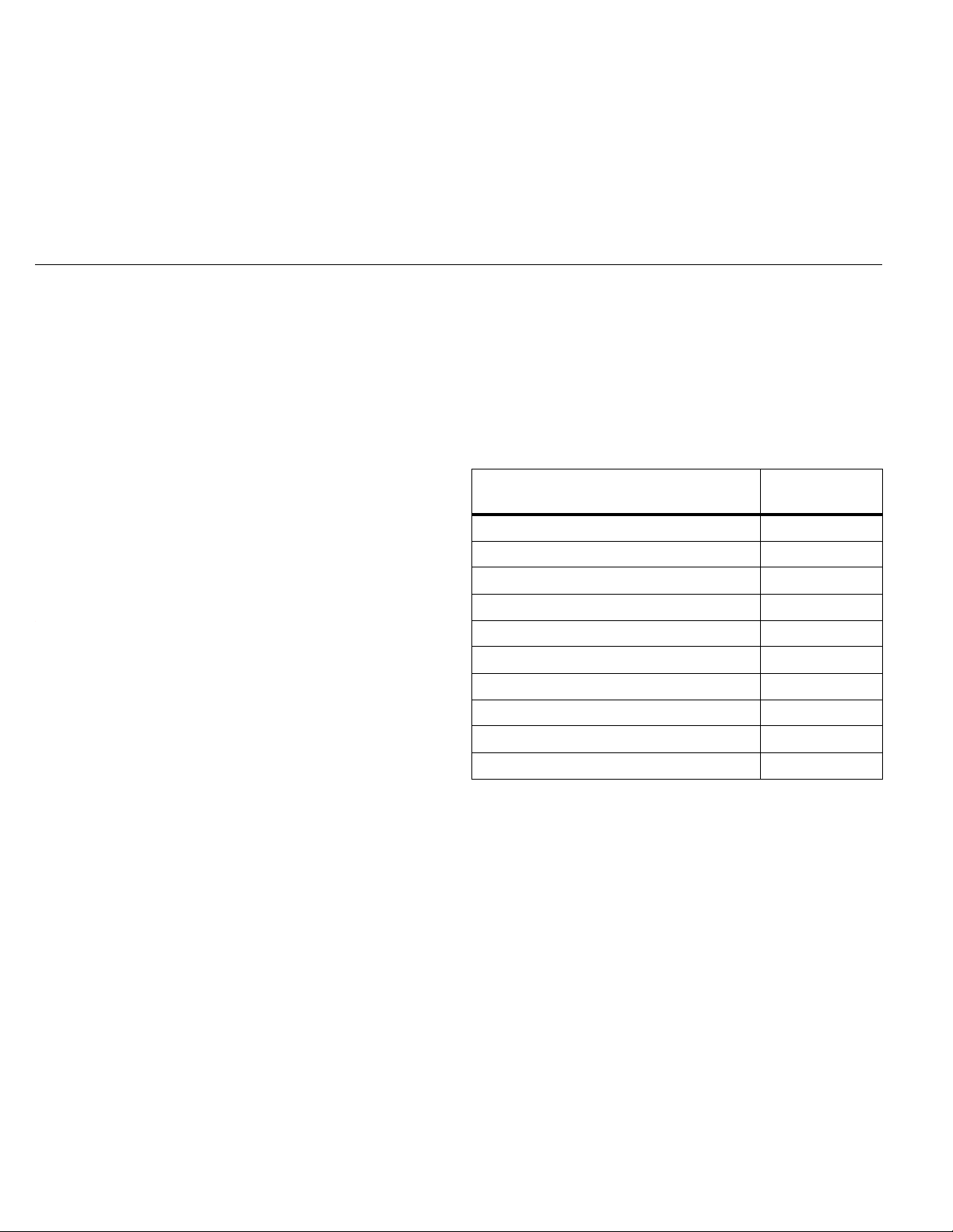
Table 6 is a list of replacement parts.
Table 6. Replacement Parts
Item/Description
Battery, AA 1.5 V (x2) 376756
Battery Door 5105034
Insulated Test Lead Set TL224
Test Probe Set TP175
Alligator Clip AC285
Flexible Current Probe i2500-10 3676410
Flexible Current Probe i2500-18 3798105
Magnet Strap 669952
Strap (9-inch) 669960
Carry Case 5211830
Fluke Part or
Model Number
18
 Loading...