

Page 1

3561 FC/3502 FC
Vibration Sensor/Gateway
Getting Started Manual
PN 5020149
July 2018
©2018 Fluke Corporation. All rights reserved. Specifications are subject to change without
notice. All product names are trademarks of their respective companies.
Find Quality Products Online at: [email protected]
www.GlobalTestSupply.com
Page 2

LIMITED WARRANTY AND LIMITATION OF LIABILITY
This Fluke product will be free from defects in material and workmanship for two
years from the date of purchase. This warranty does not cover fuses,
disposable batteries, or damage from accident, neglect, misuse, alteration,
contamination, or abnormal conditions of operation or handling. Resellers are
not authorized to extend any other warranty on Fluke’s behalf. To obtain
service during the warranty period, contact your nearest Fluke authorized
service center to obtain return authorization information, then send the product
to that Service Center with a description of the problem.
THIS WARRANTY IS YOUR ONLY REMEDY. NO OTHER WARRANTIES,
SUCH AS FITNESS FOR A PARTICULAR PURPOSE, ARE EXPRESSED OR
IMPLIED. FLUKE IS NOT LIABLE FOR ANY SPECIAL, INDIRECT,
INCIDENTAL OR CONSEQUENTIAL DAMAGES OR LOSSES, ARISING
FROM ANY CAUSE OR THEORY. Since some states or countries do not
allow the exclusion or limitation of an implied warranty or of incidental or
consequential damages, this limitation of liability may not apply to you.
11/99
Find Quality Products Online at: [email protected]
www.GlobalTestSupply.com
Page 3

Contents
Introduction ................................................................................................... 3
Before you install .......................................................................................... 4
Step 1: Watch the setup video ............................................................. 4
Step 2: Choose the connectivity option ................................................ 4
Step 3: Setup the network .................................................................... 5
Step 4: Determine asset information .................................................... 6
Step 5: Record the asset information ................................................. 10
In-app Setup ............................................................................................... 11
Step 6: Download and install Fluke Connect ..................................... 11
Step 7: Complete the in-app setup ..................................................... 12
Sensor Installation ...................................................................................... 14
Step 8: Select the Sensor location ..................................................... 14
Step 9: Confirm the Sensor and Gateway connection ....................... 15
Step 10: Mount the Sensors ............................................................... 16
Step 11: Monitor assets remotely ....................................................... 16
Specifications . ............................................................................................ 17
Find Quality Products Online at: [email protected]
www.GlobalTestSupply.com
Page 4

3561 FC/3502 FC
Getting Started Manual
A Warning identifies conditions and procedures that are dangerous to the user.
Symbols used on the Product and in this manual are explained in Table 1.
XWWarning
To prevent possible electrical shock, fire, or personal injury and for
safe operation of the Product:
• Read all safety information before you use the Product.
• Use the Product only as specified, or the protection supplied by
the product can be compromised.
• Do not use the Product if it operates incorrectly.
• Carefully read all instructions.
• Use this Product indoors only.
• Have an approved technician repair the Product
• Disable the Product if it is damaged.
• Do not use in wet location (Gateway only)
Tab le 1 . Sy mbo ls
Symbol Explanation
W
P
T
~
2
Consult User Documentation.
WARNING. RISK OF DANGER.
Conforms to European Union directives.
Conforms to relevant Australian Safety and EMC standards.
Certified by Underwriters Laboratories to North American safety standards.
Indoor use only. (Gateway)
Double Insulated (Gateway)
This product complies with the WEEE Directive marking requirements. The
affixed label indicates that you must not discard this electrical/electronic
product in domestic household waste. Product Category: With reference to
the equipment types in the WEEE Directive Annex I, this product is classed
as category 9 “Monitoring and Control Instrumentation” product. Do not
dispose of this product as unsorted municipal waste.
Find Quality Products Online at: [email protected]
www.GlobalTestSupply.com
Page 5
Introduction
The Product comprises a Fluke 3561 FC Vibration Sensor (the Sensor) and
3502 FC Gateway (the Gateway). Use the Product to monitor vibration trends
remotely through the Fluke Connect
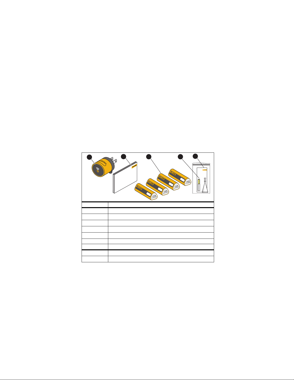
Unpack the Product
Carefully unpack all items from the box. See Table 2.
Table 2: Inside the box
1
2
Item Description Starter/Expansion kits
Not pictured Software subscription enabled for Sensors (1 year / 3 year)
3502 FC Gateway (In Starter Kit only)
Getting Started Manual
3561 FC Vibration Sensors (4)
Epoxy (2)
Epoxy application instructions
Description Gateway
3502 FC Gateway
Getting Started Manual
VIBRATION SENSOR
®
3561 FC
app.
3
VIBRATION SENSOR
XXXXX
3561 FC
VIBRATION SENSOR
XXXXX
3561 FC
VIBRATION SENSOR
XXXXX
4
3561 FC
5
XXXXX
3
Find Quality Products Online at: [email protected]
www.GlobalTestSupply.com
Page 6
3561 FC/3502 FC
Getting Started Manual
Before you install
Important: For a successful setup, follow the sequence in these
instructions.
Step 1: Watch the setup video
To see the system setup and installation, watch the video
From the Quick Start page, select 3561 FC Vibration Sensor.
Step 2: Choose the connectivity option
Option 1: WiFi connectivity must be available (2.4 GHz) at the installation
location.
OR
Option 2: Use mobile router/hotspot for connectivity. For example: Verizon
Jetpack MiFi, Cradlepoint.
4
Find Quality Products Online at: [email protected]
www.GlobalTestSupply.com
Page 7

ation Sensor/Gateway
Vibr
Before you install
Step 3: Setup the network
Note
Skip this step if you are using mobile router/hotspot for connectivity.
For this step, you will need support from your IT team.
1. Obtain the WiFi network name and password.
2. Make sure your network complies with these requirements:
WLAN Standards: 802.11 g/n GHz
Upload speed: 1Mbps (Sustained)
Internet HTTP Proxy: Disabled
Supported Authentication Protocols: WEP, WPA
For a comprehensive list of requirements, see Network
Configuration Requirement for the FC Vibration Sensor at
Find Quality Products Online at: [email protected]
www.GlobalTestSupply.com
Page 8
3561 FC/3502 FC
Getting Started Manual
Step 4: Determine asset information
Collect information on the asset (equipment) where you are installing the
Sensor. Including:
• Determine the assets
Assets are the equipment being monitored. For example, Chilled Water
Pump 2A.
• Define an asset group
An asset group is the location (building/plant/floor/production line/room) where
the asset is located. Use asset groups to set the asset hierarchy. For example,
Boiler Room.
• Select the test points
The Test Point is a specific location on the asset. For example, Motor
Bearing 1.
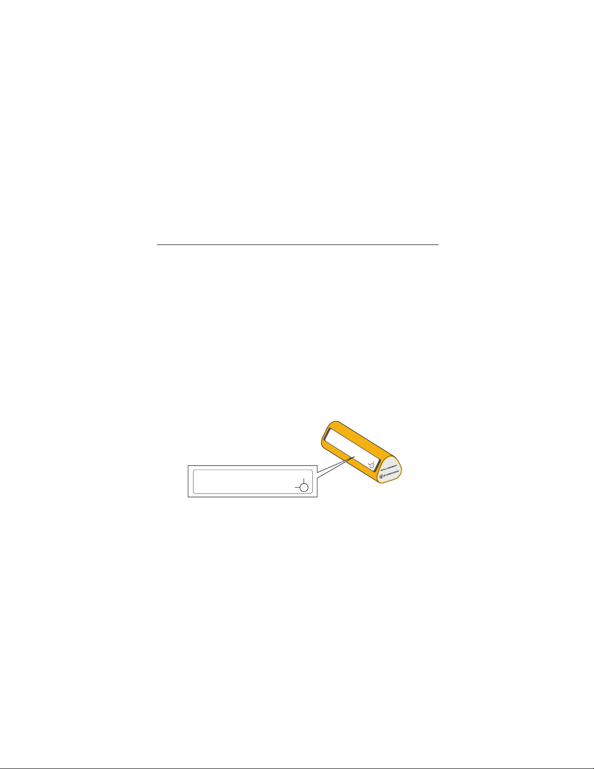
• Record the Sensor ID
The Sensor ID is the last 5 digits of the unique serial number on the Sensor.
MFG: BLUVIS
ASSEMBLED IN CHINA
ION
XXXXXXXXXXXXXXXX
DFGHJ
Z
Y
MFG: BLUVISION
ASSEMBLED IN CHINA
XXXXXXXXXXXXXXXX
DFGHJ
YZX
X
Find Quality Products Online at: [email protected]
www.GlobalTestSupply.com
Page 9

Vibration Sensor/Gateway
Before you install
• Determine the Machine Category
Machine category is a critical piece of information required to screen the health
of your assets. Choose 1 of the 37 machine categories shown in Table 3.
Table 3: Machine Categories
Pumps
Machine
Category
Description
Vertical pump (12’ to 20’ from grade to top of motor)
Vertical pump (8’ to 12’ from grade to top of motor)
Vertical pump (5’ to 8’ from grade to top of motor)
Vertical pump (0’ to 5’ from grade to top of motor)
Horizontal centrifugal end suction pump (direct coupled)
Horizontal centrifugal double suction pump (direct coupled)
Boiler feed pump (turbine or motor driven)
Positive displacement horizontal piston pump (under load)
Positive displacement horizontal gear pump (under load)
7
Find Quality Products Online at: [email protected]
www.GlobalTestSupply.com
Page 10

3561 FC/3502 FC
Getting Started Manual
Machine
Category
Description
Belt-driven fan (1800 to 3600 RPM)
Belt-driven fan (600 to 1799 RPM)
General direct drive fan (direct coupled)
Shaft-mounted integral fan (extended motor shaft)
Axial flow fan (belt or direct drive)
Large forced draft fan (fluid film bearings)
Large induced draft fan (fluid film bearings)
Vacuum blower (belt or direct drive)
Reciprocating chiller (open motor and compressor)
Reciprocating chiller (hermetic motor and compressor)
Centrifugal chiller (hermetic or open motor)
Reciprocating air compressor
Rotary screw air compressor
Centrifugal air compressor with or without gearbox
Centrifugal air compressor–internal gear (axial measurement)
Centrifugal air compressor–internal gear (radial measurement)
Fans
Compressor
8
Find Quality Products Online at: [email protected]
www.GlobalTestSupply.com
Page 11

Machine
Category
Vibration Sensor/Gateway
Before you install
Blower
Description
Lobe-type rotary blower (belt or direct drive)
Multi-stage centrifugal blower (direct drive)
Cooling Tower Drives
Long, hollow shaft (motor)
Belt-drive (motor and fan – all arrangements)
Direct drive (motor and fan – all arrangements)
Generic Gearbox
Single Stage gearbox
Machine Tools
Machine tool motor
Machine tool gearbox input
Machine tool gearbox output
Machine tool spindle – roughing operations
Machine tool spindle – machine finishing
Machine tool spindle – critical finishing
9
Find Quality Products Online at: [email protected]
www.GlobalTestSupply.com
Page 12

3561 FC/3502 FC
Getting Started Manual
Step 5: Record the asset information
Create an asset information table. For example, see Table 4.
Table 4: Asset Information
Asset Group Asset Test Point Sensor ID
Boiler room
Boiler room
Chilled Water
Pump A
Chilled Water
Pump A
Pump bearing 4 DFGHJ
Pump bearing 3 45T1S
10
Machine
Category
7. Boiler feed
pump
7. Boiler feed
pump
Find Quality Products Online at: [email protected]
www.GlobalTestSupply.com
Page 13
Vibration Sensor/Gateway
In-app Setup
Important: Complete all steps in this section before you install
the Sensor on the asset.
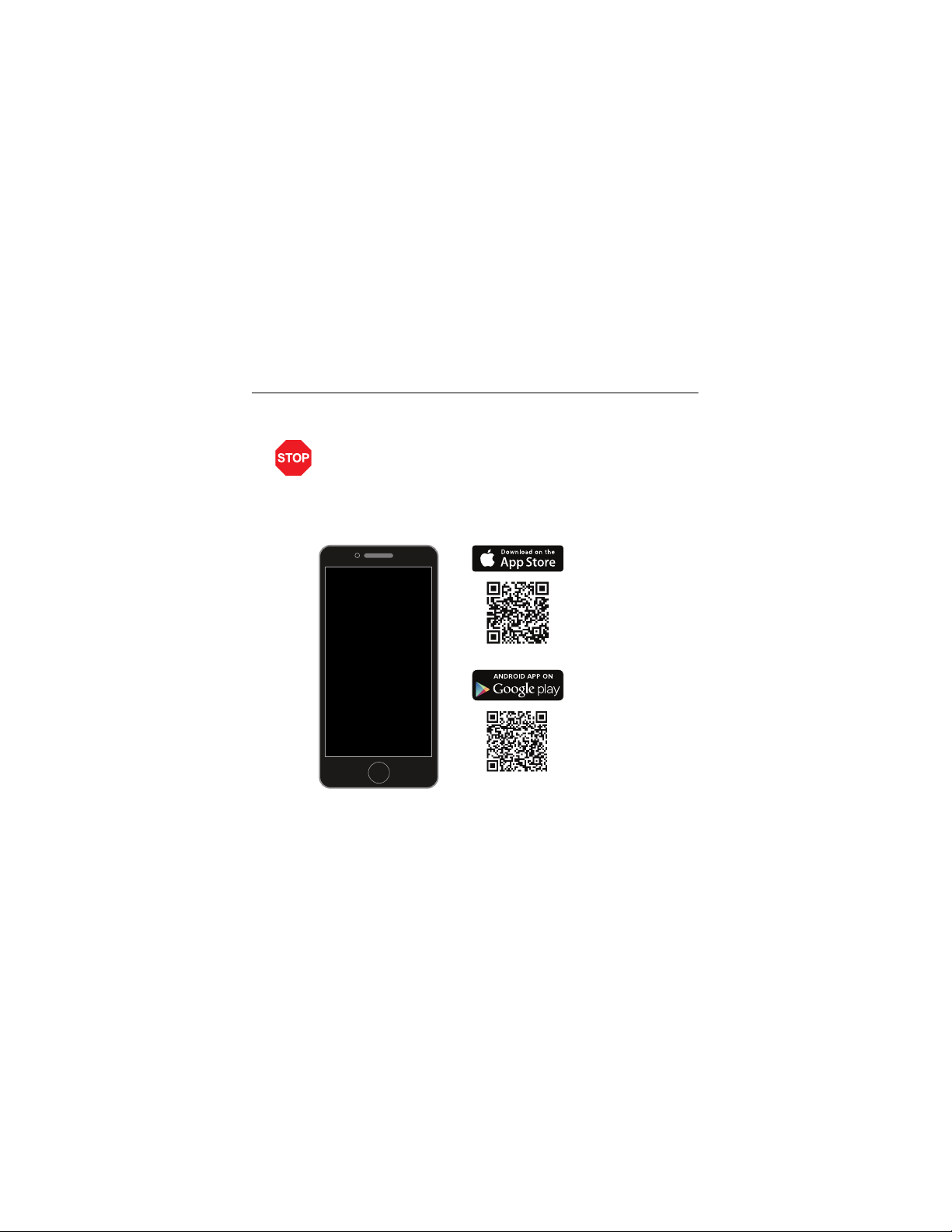
Step 6: Download and install Fluke Connect
Sign up or sign into the Fluke Connect app.
In-app Setup
11
Find Quality Products Online at: [email protected]
www.GlobalTestSupply.com
Page 14
3561 FC/3502 FC
≤10 cm
(4″)
Getting Started Manual
Step 7: Complete the in-app setup
1. Start the in-app setup on your phone.
2. Log into the Fluke Connect app.
3. On the Home screen, tap Setup Logging or Monitoring.
4. Follow the in-app instructions to complete the setup.
Important:
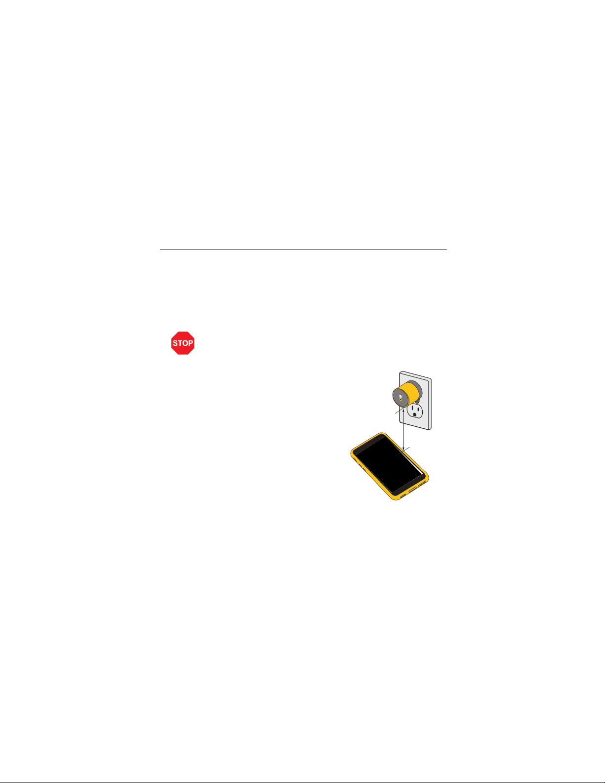
• On your mobile phone, turn on Bluetooth.
• While connecting the
Gateway on the app, hold the
phone within 4 in (10 cm)
from the Gateway and follow
the prompts.
12
Find Quality Products Online at: [email protected]
www.GlobalTestSupply.com
Page 15
Vibration Sensor/Gateway
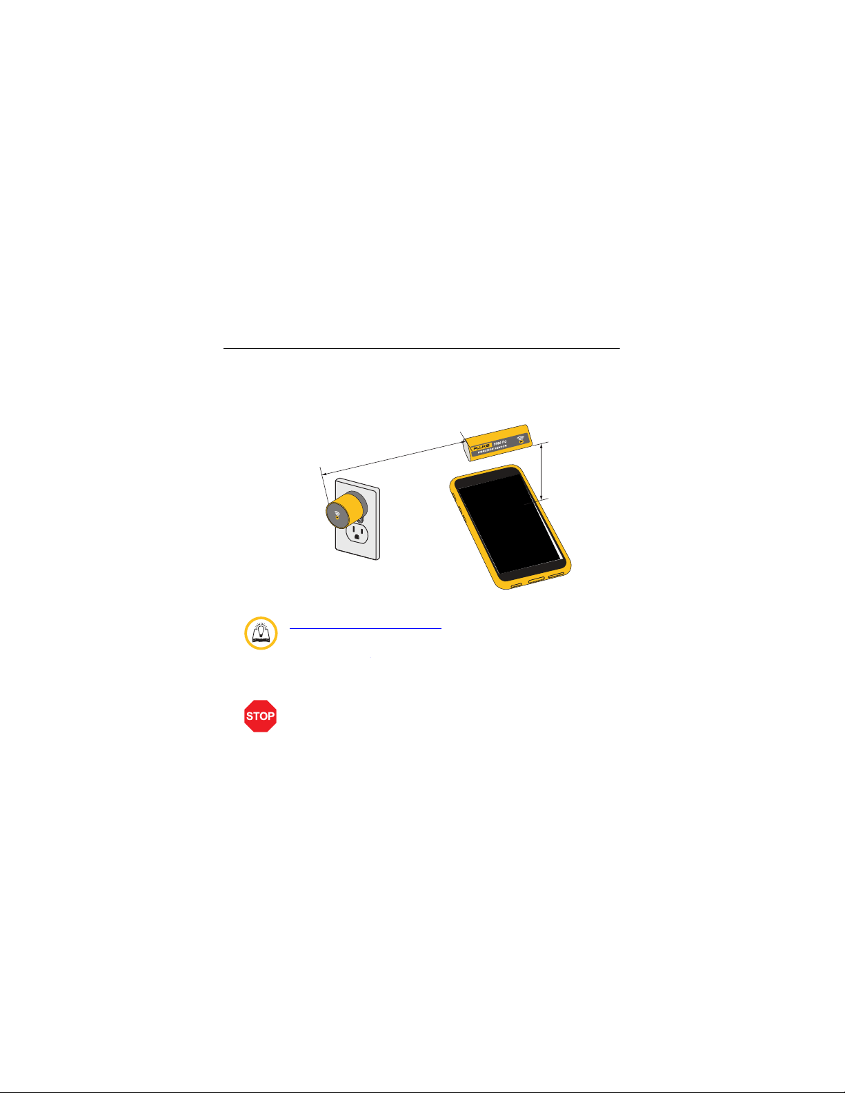
• While setting up the Sensors on the app, hold the phone
within 4 in (10 cm) from the Sensor.
• During the in-app setup, the maximum distance between
the Gateway and the Sensor must be ≤5ft (1.5m).
≤1.5 m (5')
For step-by-step guide on in-app setup, go to:
Choose 3561 FC Vibration Sensor and download Step by step in-
app setup guide.
Important: Do not begin the physical installation of the Sensors
until the data starts to stream on the graph.
In-app Setup
≤10 cm
(4″ )
13
Find Quality Products Online at: [email protected]
www.GlobalTestSupply.com
Page 16
3561 FC/3502 FC
Getting Started Manual
Sensor Installation
Important: After completing in-app setup process, wait for a few
minutes until the data appears in the session details page.
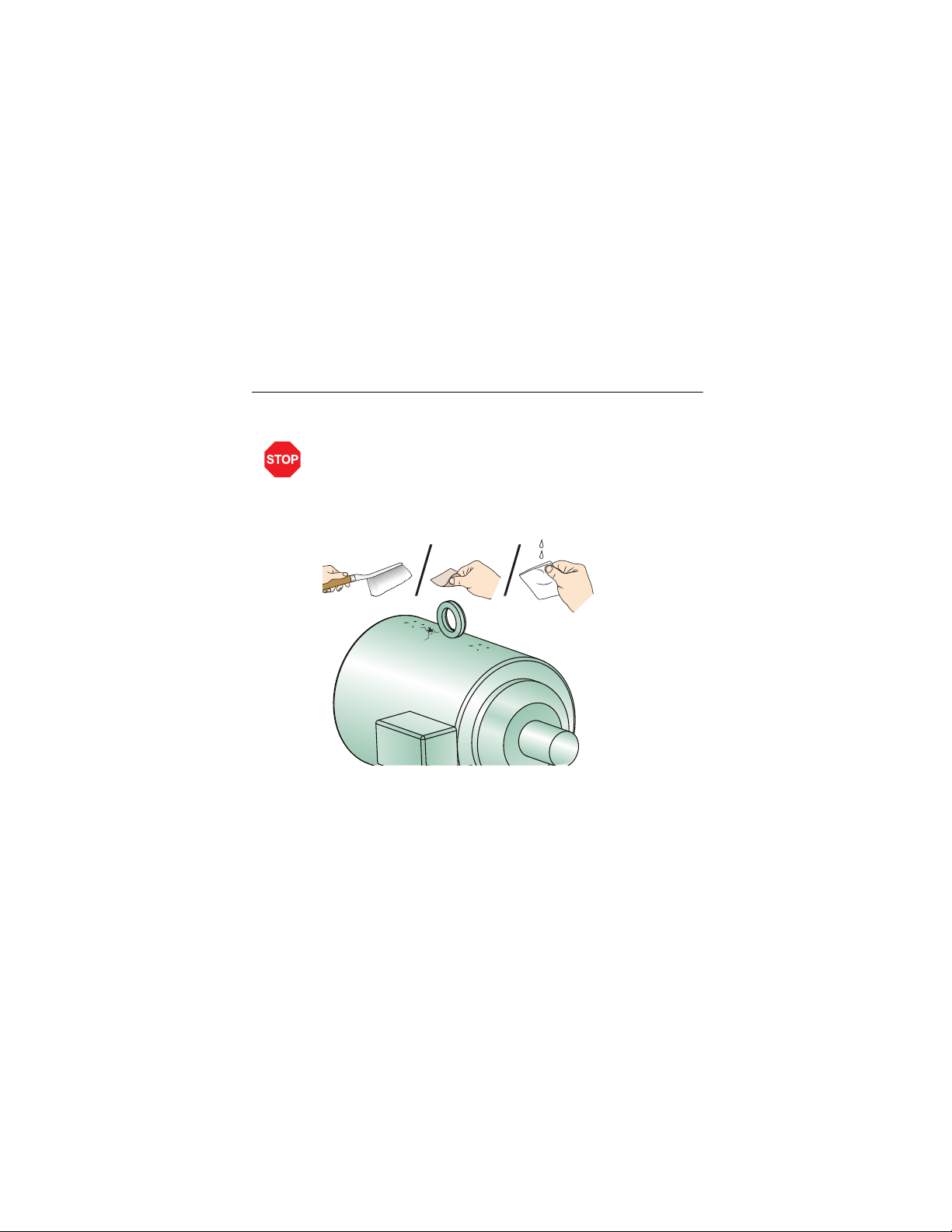
Step 8: Select the Sensor location
Clean the asset by removing chipped paint, dust, and grease from the surface.
14
Find Quality Products Online at: [email protected]
www.GlobalTestSupply.com
Page 17
Vibration Sensor/Gateway
≤65 m (213 ft)
line-of-sight
Sensor Installation
Step 9: Confirm the Sensor and Gateway connection
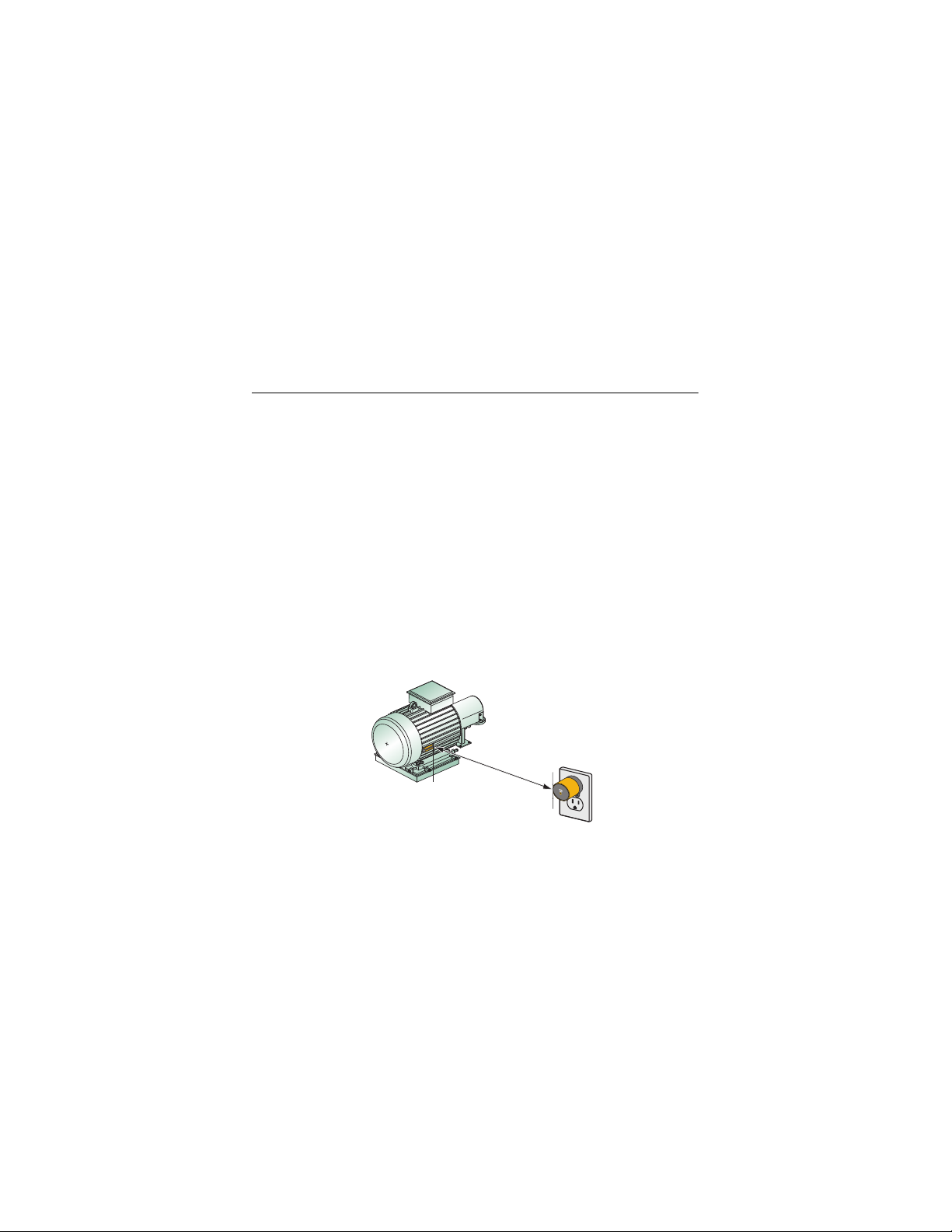
The Bluetooth range between the Gateway and Sensors is 65 m (213 ft) line-ofsight. However, this range is affected by metal and concrete around the
Sensors and Gateway. Fluke recommends these steps to make sure there is
good connectivity between Sensors and the Gateway.
1. Temporarily place the Sensors on the asset test points. (Do not install
them yet.)
2. In the app, make sure you see the alert: Sensor is now connected.
3. Monitor the the app for several minutes. Look for the alert: Sensor has lost
connection.
ο If you do not receive the alert the position is good.
ο If you receive the alert, reposition the Gateway closer to the Sensor.
Monitor the app again.
4. When the Sensor remains connected for at least 5 minutes without loosing
the connection, use epoxy to install the Sensor.
Find Quality Products Online at: [email protected]
www.GlobalTestSupply.com
Page 18
3561 FC/3502 FC
Epoxy
Getting Started Manual
Step 10: Mount the Sensors
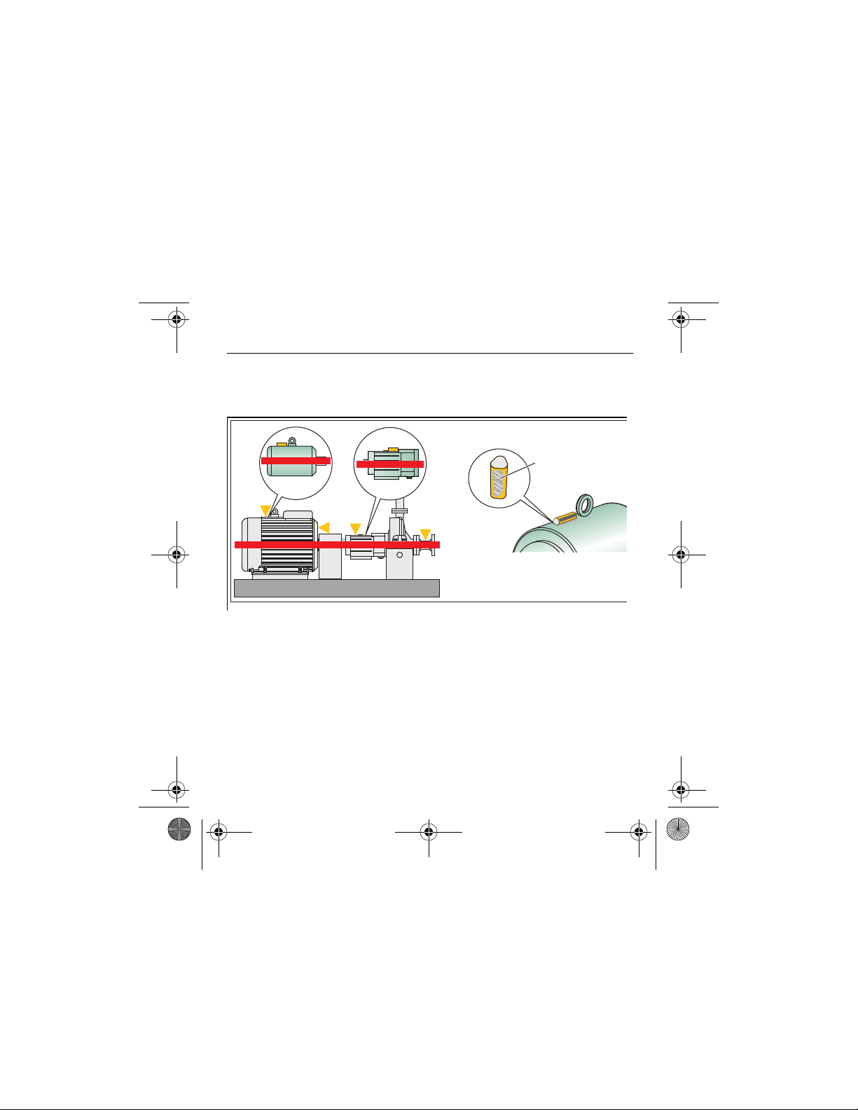
Use the epoxy provided in the package to mount the Sensor on the asset test
point. Refer to the Epoxy Application Instructions for mounting the Sensors.
Mount the Sensor on solid metal of bearing(s) of the machine. Do not mount on
thin covers, motor fins, electrical boxes, couplings, or belts. Refer to the
Deployment Planning Guide on the Quick Start page.
Step 11: Monitor assets remotely
You are now ready to remotely view vibration trends, alerts, and alarms from
your Sensors.
16
Find Quality Products Online at: [email protected]
www.GlobalTestSupply.com
Page 19

Vibration Sensor/Gateway
Specifications
Safety ..................................... IEC 60950
Sensor
Sensitivity
Range ........................ ±32 g
Frequency Range ...... 10 Hz to 1000 Hz
Sampling Rate ........... 25 600 Hz
Temperature
Operating ................... -30 °C to +80 °C (-20 °F to +176 °F)
Storage ...................... -30 °C to +80 °C (-20 °F to +176 °F)
Trending Range ......... Displays temperature trends between -30 °C
and +80 °C (-20 °F and +176 °F)
Relative Humidity ........... 10 % to 95 % non-condensing
Altitude
Operating ................... 2000 m
Storage ...................... 12 000 m
Size ................................ 2.42 in x 0.95 in (61.5 mm x 24 mm)
Weight ............................ 1.4 oz (28 g)
Power
Battery Type............... 3.6 V, 2400 mAh Lithium
Battery Life................. 3 years typical
Bluetooth
Type ........................... Low Energy 4.1
Range ........................ 65 m, line-of-sight (during a session)
Frequency Range ...... 2405 MHz to 2480 MHz
Output Power ............. <10 mW
IP Rating ........................ IP67
Specifications
17
Find Quality Products Online at: [email protected]
www.GlobalTestSupply.com
Page 20

3561 FC/3502 FC
Getting Started Manual
Gateway
Temperature
Operating Range ............ -25 °C to +65 °C (-13 °F to +149 °F)
Storage........................... -25 °C to +65 °C (-22 °F to +149 °F)
Relative Humidity ...............10 % to 95 % non-condensing
Altitude
Operating........................ 2000 m
Storage........................... 12 000 m
Size .................................... 2.26 in x 1.55 in x 1.82 in
Weight ................................ 1.2 oz (35 g)
Power
AC Input ......................... 100 V ac to 240 V ac, 50/60 Hz
Bluetooth
Type ............................... Low Energy 4.1
Frequency Range........... 2405 MHz to 2480 MHz
Output Power ................. <10 mW
Antenna.......................... -3 dBm Single Antenna, Omni Directional
WiFi
Type ............................... 802.11 b/g/n
Frequency Band ............. 2.4 GHz ISM Band
Frequency Range........... 2412 MHz to 2462 MHz
Output Power ................. <100 mW
Security .......................... WEP/WPA/WPA2
Antenna.......................... 0 dBm Single Antenna, Omni Directional
Signal Strength............... Less than -65 to -70 dBm
(57.3 mm x 39.3 mm x 46.1 mm)
18
Find Quality Products Online at: [email protected]
www.GlobalTestSupply.com
 Loading...