

Page 1

35040
Therapy Dosimeter
February 2005
Manual No. 37870 Rev. 10
©2004, 2005 Fluke Corporation, All rights reserved. Printed in U.S.A.
All product names are trademarks of their respective companies
Operators Manual
Page 2

Fluke Biomedical
Radiation Management Services
6045 Cochran Road
Cleveland, Ohio 44139
440.498.2564
120 Andrews Road
Hicksville, New York 11801
516.870.0100
www.flukebiomedical.com/rms
Page 3

Table of Contents
Section 1: General Information................................................................................... 1-1
1.1 Introduction ............................................................................................................................ 1-1
1.2 Features ................................................................................................................................. 1-1
1.3 Before you Start - Safety Precautions.................................................................................... 1-2
1.4 Safety Symbols and Terms....................................................................................................1-2
1.5 Manual Addenda.................................................................................................................... 1-3
1.6 Specifications ......................................................................................................................... 1-3
1.7 Unpacking and Inspection...................................................................................................... 1-7
Section 2: Theory Of Operation.................................................................................. 2-1
2.1 Introduction ............................................................................................................................ 2-1
2.2 Functional Description............................................................................................................ 2-1
2.2.1 Power Supply .................................................................................................................. 2-2
2.2.2 Front Panel ...................................................................................................................... 2-2
2.2.3 MicroController ................................................................................................................ 2-2
2.2.4 Serial Communications Port............................................................................................ 2-2
2.2.5 Electrometer .................................................................................................................... 2-2
2.2.6 Bias Supply...................................................................................................................... 2-3
2.2.7 Multiplexer and A/D Converter ........................................................................................ 2-3
2.3 Basic Operating Equations .................................................................................................... 2-3
2.3.1 Setting Thresholds........................................................................................................... 2-7
2.3.2 Exposure Time ................................................................................................................ 2-8
2.3.3 Air Density Correction Factor .......................................................................................... 2-9
Section 3: Operation.................................................................................................... 3-1
3.1 Setup...................................................................................................................................... 3-1
3.2 Front Panel Familiarization .................................................................................................... 3-1
3.3 Rear Panel Familiarization..................................................................................................... 3-2
3.4 Powering the System ............................................................................................................. 3-2
3.5 Power-Up Self-Test and Display Messages .......................................................................... 3-3
3.6 Ion Chamber Connector......................................................................................................... 3-3
3.7 Basic Measurement Techniques............................................................................................ 3-4
3.7.1 General Considerations................................................................................................... 3-4
3.7.2 Making Non-Timed Exposure Measurements................................................................. 3-4
3.7.3 Making Timed Exposure Measurements ............................................................3-5
3.7.4 Using Other Ion Chambers.............................................................................................. 3-6
3.8 Battery Care ........................................................................................................................... 3-6
3.9 Operation Instructions............................................................................................................ 3-7
3.9.1 Front Panel Controls........................................................................................................ 3-7
3.9.2 Powering Up the Model 35040 Therapy Dosimeter ........................................................ 3-8
3.9.3 Powering Down the Model 35040 Therapy Dosimeter.................................................... 3-9
3.9.4 Using the Test Function Button ....................................................................................... 3-9
3.9.5 Automatic Leakage Compensation ............................................................................... 3-11
3.9.6 Timer Setup ................................................................................................................... 3-13
3.9.7 Setting Thresholds......................................................................................................... 3-13
3.9.8 Using the Detector Select Button .................................................................................. 3-14
3.9.9 Using the Air Density Button.......................................................................................... 3-14
Section 3: Operation .............................................................................................. 3-1
3.9.10 Using the Units Select Button........................................................................................ 3-15
3.9.11 Using the Bias Select Button ......................................................................................... 3-15
i
Page 4

3.9.12 Using the Reset/Measure Button .................................................................................. 3-17
3.9.13 Overrange Conditions.................................................................................................... 3-17
3.9.14 Reset Error .................................................................................................................... 3-18
3.9.15 Reset Error (With Automatic Leakage Compensation Enabled)................................... 3-19
3.9.16 Annunciators.................................................................................................................. 3-19
3.10 Customization ...................................................................................................................... 3-21
3.10.1 Introduction.................................................................................................................... 3-21
3.10.2 Installing/Uninstalling Customization Software.............................................................. 3-21
3.10.3 Connection to the Computer.......................................................................................... 3-21
3.10.4 Starting the Customization Software ............................................................................. 3-21
3.10.5 Downloading.................................................................................................................. 3-22
3.10.6 Menu Items and Controls .............................................................................................. 3-22
3.10.7 Ion Chambers ................................................................................................................ 3-23
3.10.8 Special Items ................................................................................................................. 3-25
3.10.9 Measurement Displays .................................................................................................. 3-26
3.10.10 Timer Intervals............................................................................................................... 3-30
3.10.11 Bias Settings.................................................................................................................. 3-31
3.10.12 Examples....................................................................................................................... 3-32
3.10.13 Errors ............................................................................................................................. 3-34
Section 4: Troubleshooting and Service ................................................................... 4-1
4.1 Introduction ............................................................................................................................ 4-1
4.2 Troubleshooting ..................................................................................................................... 4-1
4.3 Display Will Not Light ............................................................................................................. 4-6
4.4 Low Battery ............................................................................................................................ 4-7
4.5 Bias Error ............................................................................................................................... 4-8
4.6 Line Fuse Replacement ......................................................................................................... 4-9
4.7 Interface Connector Cleaning .............................................................................................. 4-10
4.8 Cleaning the Instrument....................................................................................................... 4-10
4.9 Replacement Parts Information ........................................................................................... 4-10
4.10 Recalibration, Repair Information & Technical Assistance.................................................. 4-11
4.11 Warranty Information............................................................................................................ 4-11
Appendix A: Sample Customization Reports ................................................................A-1
A.1 Sample Documents................................................................................................................ A-1
Appendix B: Addendum Features of Firmware Version “27JAN00” or Later .............B-1
B.1 Introduction ............................................................................................................................ B-1
B.2 New Features......................................................................................................................... B-1
B.2.1 Overview.......................................................................................................................... B-1
B.2.2 Timed Measurements...................................................................................................... B-1
B.2.3 Specifications Update...................................................................................................... B-2
B.3 Setup...................................................................................................................................... B-3
B.3.1 Making Non-Timed Exposure Measurements................................................................. B-3
B.3.2 Making Timed Exposure Measurements......................................................................... B-4
B.4 Operation Instructions............................................................................................................ B-5
B.4.1 Front Panel Controls........................................................................................................ B-5
B.4.2 Using the Test Function Button ....................................................................................... B-6
B.4.3 Automatic Leakage Compensation ................................................................................. B-6
B.4.4 Timer Setup ..................................................................................................................... B-8
ii
Page 5

Appendix B: Addendum Features of Firmware Version “27JAN00” or Later .............B-1
B.4.5 Reset Error (with Automatic Leakage Compensation Enabled)...................................... B-8
B.4.6 Annuciators, Indicators, and Overrange Conditions........................................................ B-9
B.5 Theory of Operation ............................................................................................................. B-11
B.6 Troubleshooting ................................................................................................................... B-12
B.7 Customization ...................................................................................................................... B-13
B.7.1 The Main Menu.............................................................................................................. B-13
B.7.2 The Measurement Menu ...............................................................................................B-13
iii
Page 6

(Blank page)
Page 7

1.1 Introduction
General Information
Introduction
1
Section 1
General Information
The Model 35040 Therapy Dosimeter is designed for calibration dosimetry of therapeutic radiation
treatment machines including high-energy accelerators,
instrument can be used for calibration, government compliance testing, installation and set-up of new
equipment, and troubleshooting.
The Model 35040 Therapy Dosimeter is a reference grade instrument that exceeds calibration
laboratories’ 1993 recommendations for linearity, long-term stability, and zero drift. The instrument uses
calibrated ion chambers to simultaneously measure and display dose and dose rate in the user specified
radiological units. At the user’s discretion, the reading may be corrected for air density by user entered
ambient temperature and barometric pressure readings.
• The highly regulated, precision electronic bias is continuously monitored. The bias voltage may be
selected from the front panel.
• The Model 35040 Therapy Dosimeter provides a timer for performing timed charge and dose
measurements. A typical application of the timer is for measuring brachytherapy sources. The
instrument supplies four timed measurement quantities, which may be added to any of the
measurement displays with the Customization software
• Triaxial ion chamber input connectors are furnished on both the front and rear of the instrument to
make it easier to set up and use.
• For the first time in a therapy dosimeter, the effective exposure time for
from a single exposure.
60
Co, and brachytherapy equipment. The
60
Co source is determined
1.2 Features
• Low leakage current in the instrument.
• All front panel settings are stored at power down and recalled at power up.
• A wide variety of measurements are available simultaneously; including charge, dose, current, dose
rate, accumulated charge, accumulated dose, and effective exposure time.
• Timer for performing timed charge, predicted time charge and corresponding dose measurements.
• The user may select one of 32 ion chamber calibration factors for direct readout of dose or dose
rate units.
• Dose measurement values may be displayed in units of Roentgens, rads, Sieverts, or Grays. Dose
rate measurement values may be displayed in dose units per second, minute or hour. For
brachytherapy applications, the instrument may be configured to read in Curies, becquerles, or
kerma.
• The user may enter ambient temperature and pressure for air density correction of dose and dose
rate measurements. Air density correction may be turned on or off from the front panel.
• The user may select the dose rate time divisor from the front panel.
1-1
Page 8
35040
Operators Manual
• The ion chamber bias voltage may be set to one of 11 user-customized settings. The display
indicates the polarity of the central electrode and the actual measured output voltage generated by
the ion chamber bias supply.
• Highly regulated, stable, electronic ion chamber bias supply.
• The level of the internal electronic bias supply is continuously monitored. Annunciators appear on
the display if an abnormal bias voltage level is detected.
• Bright, clear, multi-line alphanumeric display.
• Simplified, uncluttered control panel.
• A wide AC line input range of 100 to 240 VAC and the use of an IEC 320/C13 style receptacle
provide worldwide operation by use of the proper line cord.
• The system may be operated from either AC line power source or from its internal battery. The
battery will be charged from AC line power during use.
• A high performance rechargeable battery system provides 8 hours of continuous operation from a
3-hour charge. A low battery annunciator indicates when 30 minutes or less of operation remains.
• Automatic power-down after a user-specified time period, when operating from battery power.
1.3 Before You Start - Safety Precautions
The Model 35040 Therapy Dosimeter should be used only by people who are:
• Aware of and understand the limitations of the device as they relate to the measurement of
radiation output
• Knowledgeable about safety procedures observed when working with radiation sources, such as
therapy radiation machines
• Aware of safety precautions required to avoid possible injury when using electrical/electronic
equipment
NOTE
The Model 35040 Therapy Dosimeter is NOT
approved for applications where the sensor or the
dosimeter is in contact with the patient.
Please take the time to read this manual carefully before operating this instrument.
1.4 Safety Symbols And Terms
The following symbols and terms are found on the instrument and used in this manual.
The symbol on the instrument indicates that the user should refer to the operating instructions
located in the manual.
The symbol on the instrument shows that high voltage may be present on the terminal(s). Use
standard safety precautions to avoid personal contact with these voltages.
The heading used in this manual explains dangers that might result in personal injury or
death. Always read the associated information very carefully before performing the indicated procedure.
WARNING
1-2
Page 9
General Information
Safety Symbols and Terms
1
The heading used in this manual explains hazards that could damage the instrument.
Such damage may invalidate the warranty.
CAUTION
1.5 Manual Addenda
Any improvements or changes concerning the instrument or manual will be explained in an addendum
included with the manual. Be sure to note these changes and incorporate them into the manual.
1.6 Specifications
Charge Measurements
Range, Resolution and Repeatability:
Full Scale Range Display Resolution
200.00 pC 0.01 pC 5
2.0000 nC 0.0001 nC 1.5
20.000 nC 0.001 nC 2.5
200.00 nC 0.01 nC 1
2.0000 μC 0.0001 μC
20.000 μC 0.001 μC
200.00 μC 0.01 μC
2.0000 mC 0.0001 mC 1
20.000 mC 0.001 mC 1
Measurement Method: Charge flowing into the input is integrated using a capacitive feedback
electrometer whose output is measured by means of a 20 bit bipolar A-D converter. A high-speed reset
circuit removes the integrated charge on the feedback capacitor each time it reaches a level of 2 nC in
either polarity. By monitoring both the number of 2 nC resets and the charge on the feedback capacitor,
the total charge flowing into the input is determined.
Repeatability (±
counts)
1
1
1
Factory Calibration: Basic factory charge calibration is performed by injecting -1.90 nC and
a precision standard air capacitor. This method is believed to provide a calibration accuracy of
0.05%rdg (± 0.05% of reading) as detailed in the table below:
Factory Calibration Error Source ± (%rdg)
Charge Source Accuracy (Capacitor) 0.01
Charge Source Accuracy (Voltage Change) 0.01
Temperature Effects (21°C – 25°C) 0.02
Other 0.01
Maximum Error 0.05
The field adjustable current and charge scale factors are set to their nominal value of 1.000 during factory
recalibration.
± 19.0 nC via
±
1-3
Page 10

35040
Operators Manual
Measurement Accuracy: Charge measurement accuracy is warranted to be better than ±
(0.20%rdg + 2
counts) over the operating temperature range of 18°C to 28°C for 1 year.
Field Calibration: Field calibrations may be performed via a restricted distribution MS-DOS Calibration
program. This program is available to the AAPM accredited calibration laboratories (or equivalent) and
may be used to adjust the current and charge scale factors from their nominal factory setting of 1.000.
Timed Charge Measurements
Range and Resolution: Same as charge measurements.
Measurement Method: The timed charge measurement is derived by monitoring the charge integrated
over a time interval that begins with the activation of the timer. The timer automatically stops when the
elapsed time is equal to the timer interval setting or the exposure is over. Interpolation is used to
determine the charge at an integral number of seconds.
Measurement Accuracy: Same as charge measurements assuming that the rate of charge delivery does
not dramatically change within the interpolation window interval.
Current Measurements
Range, Resolution, and Noise:
Full Scale Range Display Resolution
Noise
(± counts)
200.0 pA 0.1 pA 2
2.000 nA 0.001 nA 2
20.00 nA 0.01 nA 1
200.0 nA 0.1 nA 1
1.000 μA 0.001 μA
1
Measurement Method: The basic current measurement is derived by monitoring the change in the
integrated charge level over successive 1-second intervals. Dividing the change in integrated charge by
the 1-second integration period interval yields the current value.
Measurement Accuracy: Current measurement accuracy is ±
(0.20%rdg + 2 counts) over the operating
temperature range of 18°C to 28°C for 1 year. Since the current measurements are based directly upon
charge measurements, an independent current calibration is not required.
Measurement Noise: Current measurement noise is typically 1 to 4 counts peak to peak (depending
upon the range) when the input is supplied by a quiet DC current source. When using a 0.6 cc Farmer
Probe to measure the output of a typical
60
Co source, noise in the current measurement may be on the
order of 0.4 R/min peak to peak at 100 R/min. Normal variations in the output exposure rate produced by
a linear accelerator may result in excessive noise on the current measurement.
Response Speed: The display of current measurement values will begin within 1 second of the start of
the exposure and reach 99% of the final level within 2 seconds.
Average Current Measurements
Range and Resolution:
Full Scale Range Display Resolution
200.00 pA 0.01 pA
2.0000 nA 0.0001 nA
20.000 nA 0.001 nA
200.00 nA 0.01 nA
1-4
Page 11

General Information
Specifications
1.0000 μA 0.0001 μA
Measurement Method: Average current measurement is derived by monitoring the charge integrated
over the time interval beginning 1.33 seconds after the detection of the start of the exposure, and ending
1.33 seconds prior to the detection of the end of the exposure. Dividing the charge integrated over this
interval by duration of the time interval yields the average current value.
Measurement Accuracy: The accuracy of the average current value in %rdg is approximately equal to
the accuracy of the integrated charge measurement value from which it is produced. This value may be
calculated by converting the “counts” contribution to a %rdg and summing this value with the inherent
0.20%rdg base accuracy of the charge measurement. Since the average current measurements are
based directly upon charge measurements, an independent current calibration is not required.
Measurement Noise: Average current measurement noise decreases as the integration time interval
increases. Typically, the noise in the average current measurement after a 100 second integration
interval will be 10 times less than is present in the current measurement.
Response Speed: The display of average current measurement values will begin within 4 seconds of the
start of the exposure.
1
Effective Exposure Time Measurements
Range and Resolution:
Full Scale Range
Seconds Hours/Minutes/Seconds
59.99 s 59.99 s 0.01 s
19,999.9 s 5 h 33 min 19.9 s 0.1 s
Measurement Method: The effective exposure time value is calculated as the quotient of the charge and
average current measurement values. A minimum exposure duration of 3.5 seconds is required to
produce an effective exposure time measurement value.
Measurement Accuracy: Although the accuracy of the effective exposure time measurement value is
directly dependent upon the accuracy of the internal oscillator frequency (better than ± 0.01%), more
important to the achievable accuracy of this measurement are the effects of linearity and noise in the
exposure and average current measurement values upon which it is based. In practice, an upper limit of
the error in the exposure time value in %rdg will be equal to the %rdg noise observed in the average
current display values.
Response Speed: The display of effective exposure time values will begin within 4 seconds of the start of
the exposure.
Display Resolution
General Measurements
Dose Conversion: Dose measurement values are calculated by forming the product of the measured
charge, ion chamber calibration factor, and the air density correction factor.
Dose Rate Conversion: Dose Rate measurement values are calculated by forming the product of the
measured current, ion chamber calibration factor, air density correction factor, and time unit multiplier.
Measurement Non-Linearity: The maximum variation from a straight line is ± 0.1% of range on all charge
and current ranges.
Long Term Stability: Ultra high long-term stability on the order of 0.1% per 5 years for both charge and
current measurements is expected. Long-term measurement stability is verified as a part of each factory
recalibration using inputs of -1.90 nC and ± 19.0 nC for charge and 19.0 nA for current. Compliance to
the warranted specifications is considered satisfied if the observed measurement errors (%rdg) meet the
following equations:
1-5
Page 12

35040
Operators Manual
Period
[ Error Charge Observed +×≤
5
0.10%0.10%]
and
Period
[ Error Current Observed +×≤
5
0.15%0.10%]
where “Period” is the time interval in years between calibrations.
Gain Temperature Stability: The maximum temperature effect is less than ± 0.05%rdg for both charge
and current measurements over operating range of 18°C to 28°C. Add an additional ± 0.05%rdg for
operation during and immediately following battery charging at the high rate. Add an additional ±
0.01%rdg/°C for operation over the ranges of (8°C to 18°C) and (28°C to 38°C).
AC Line Gain Stability: The maximum AC line voltage effect is less than ± 0.02%rdg over the full
operating range of 100 to 240 VAC (47 - 63 Hz).
Maximum Input Current: To achieve the stated measurement accuracy, the instantaneous input current
must be limited to less than ± 100 nA.
Input Protection: The electrometer input is protected by a 100 kW ± 10% series resistor. The maximum
input current level of 3 mA should never be exceeded. Currents above this level may damage the
instrument.
Exposure Threshold: The start and end exposure thresholds are adjustable from the front panel over the
range of 0.0 to 9.9 pA in 0.1 pA steps. Setting the start exposure threshold to 0.0 pA disables the
automatic exposure detection system and turns off both the automatic reset and current leakage
compensation features. When the start exposure threshold is set above 0.0 pA, the leakage
compensation feature operates by automatically subtracting the leakage current value from the measured
current throughout the duration of the exposure. Both the displayed current and charge values are thus
compensated for leakage current effects. The leakage current value used in this compensation is derived
by averaging the current over the 10 s period immediately prior to the start of the exposure.
Current Leakage: Dosimeter input leakage is warranted to be less than 10 fA over both the full operating
temperature range of 8°C to 38°C and for humidities up to 80% R.H., but only for conditions in which the
3
absolute humidity is £ 20 g/m
(the equivalent R.H. is 75% at 25°C, 60% at 30°C, and 50% at 35°C).
Stabilization Time: The instrument is warranted to meet its measurement accuracy and current leakage
specifications within 2 minutes of power up. A maximum of 2 minutes may be required for the leakage
current to stabilize to below the 10 fA level following a change to the ion chamber bias voltage selection
(exclusive of ion chamber and cable effects). The instrument is warranted to meet its measurement
accuracy specifications within 1 hour of power up.
Input Connectors: Two female triaxial type mounted on front and rear panels and connected in parallel.
High Performance Power Supply and Battery Charger
AC Line Input Voltage Range: 100 to 240 VAC (47 - 63 Hz) without operator switching.
AC Line Input Receptacle: IEC 320/C13 style with integral fuse holder located on the rear panel.
AC Line Protection Fuse: 5 x 20 mm IEC type F1H250V fuses are used.
Battery Type and Capacity: Lead acid battery provides 8 hours of continuous operation.
Recharge Time: Fast recharge time less than 3 hours to the full charge level, even during operation.
Low Battery Annunciator: “LoBat” is displayed when the battery voltage drops below 5.9 V. To protect
the battery from deep discharge, the unit automatically powers down when the battery voltage drops
below the level of 5.4 V. The instrument will operate for approximately 30 minutes with the “LoBat”
annunciator displayed before automatically powering down.
Automatic Power Down: The instrument may be customized by the user (via the supplied Customization
program) to automatically power down after a preset period of inactivity (lack of a key press, RS-232
1-6
Page 13

General Information
Specifications
command, or exposure detection). The automatic power down feature applies only when the instrument
is operating from battery power. In addition, all front panel settings are saved as part of the automatic
power down sequence.
1
Internal Electronic High Voltage Ion Chamber Bias Supply
Voltage Range: A maximum of 11 output level settings in the range of -500 V to +500 V may be
programmed during user customization. Once programmed, these output levels become available for use
and may be selected from either the front panel or via the RS-232 interface.
Level Accuracy: Bias voltage is warranted to be within ± 0.3 V over the full operating temperature range
for loads < 0.2 mA.
Internal Verification: The voltage level is continuously measured during operation and compared to the
selected setting. A “LoBias” or “HiBias” annunciator is displayed if the measured level differs from the
selected setting by more than 1 V.
Capacitive Loading: Maximum ion chamber cable capacitance is 5,000 pF from ground to guard or from
guard to center. For a typical 100 pF per meter triaxial cable, the maximum cable length is therefore 50
meters.
Output Current Limit: The output current is limited to < 0.5 mA for operator safety.
General
RS-232 Interface: Single RJ-45 style jack mounted on rear panel. Interface operates at 9600 bps, with 8
bits, no parity, and one stop bit. Xon/Xoff handshaking is employed.
Display: 4 line by 20 character vacuum florescent type.
Environment
Operating: 8°C to 38°C with an absolute humidity of £ 20 g/m3 (the equivalent R.H. is 75% at 25°C, 60%
at 30°C, 50% at 35°C).
Storage: -25°C to +65°C. For maximum battery life, always bring the batteries to a level of full charge
prior to storage, and maintain the storage temperature at 25°C or below. Under these conditions the
batteries should receive an annual maintenance recharge to compensate for the self-discharge effects.
Decrease the time interval between maintenance recharges by one-half for each 10°C increase in storage
temperature above the 25°C baseline.
Mechanical
Dimensions: 21.6 cm wide x 8.9 cm high x 26 cm deep (10 in. x 9.4 in. x 4 in.).
Weight: 4.5 kg (10 lbs.).
1.7 Unpacking and Inspection
The Model 35040 Therapy Dosimeter was carefully inspected before shipment. Upon receiving the Model
35040 Therapy Dosimeter, carefully unpack all items from the shipping carton and check for any obvious
signs of physical damage that might have occurred during shipment. Report any damage to the shipping
agent at once. Retain the original packing material in case reshipment becomes necessary. The
following items are included with the Model 35040 Therapy Dosimeter:
Standard System Contents
• Model 35040 Therapy Dosimeter
• AC Line Cord – USA (CO-19)
• Customization Software Kit (37886)
1-7
Page 14

35040
Operators Manual
- CD, 35040 Standard Customization (37870CD)
- 9-pin connector adaptor (37616)
- 7 foot RJ-45 Cable (105-260)
1-8
Page 15
2.1 Introduction
Theory of Operation
Introduction
2
Section 2
Theory of Operation
The Model 35040 Therapy Dosimeter is a radiation measurement instrument intended for use in
60
calibration procedures for high-energy accelerators,
Co, and brachytherapy. Basic theory of operation
of the instrument is explained in the following paragraphs. For information on radiation dosimetry and ion
chamber measurement theory, the reader should refer to one of the standard radiological physics texts.
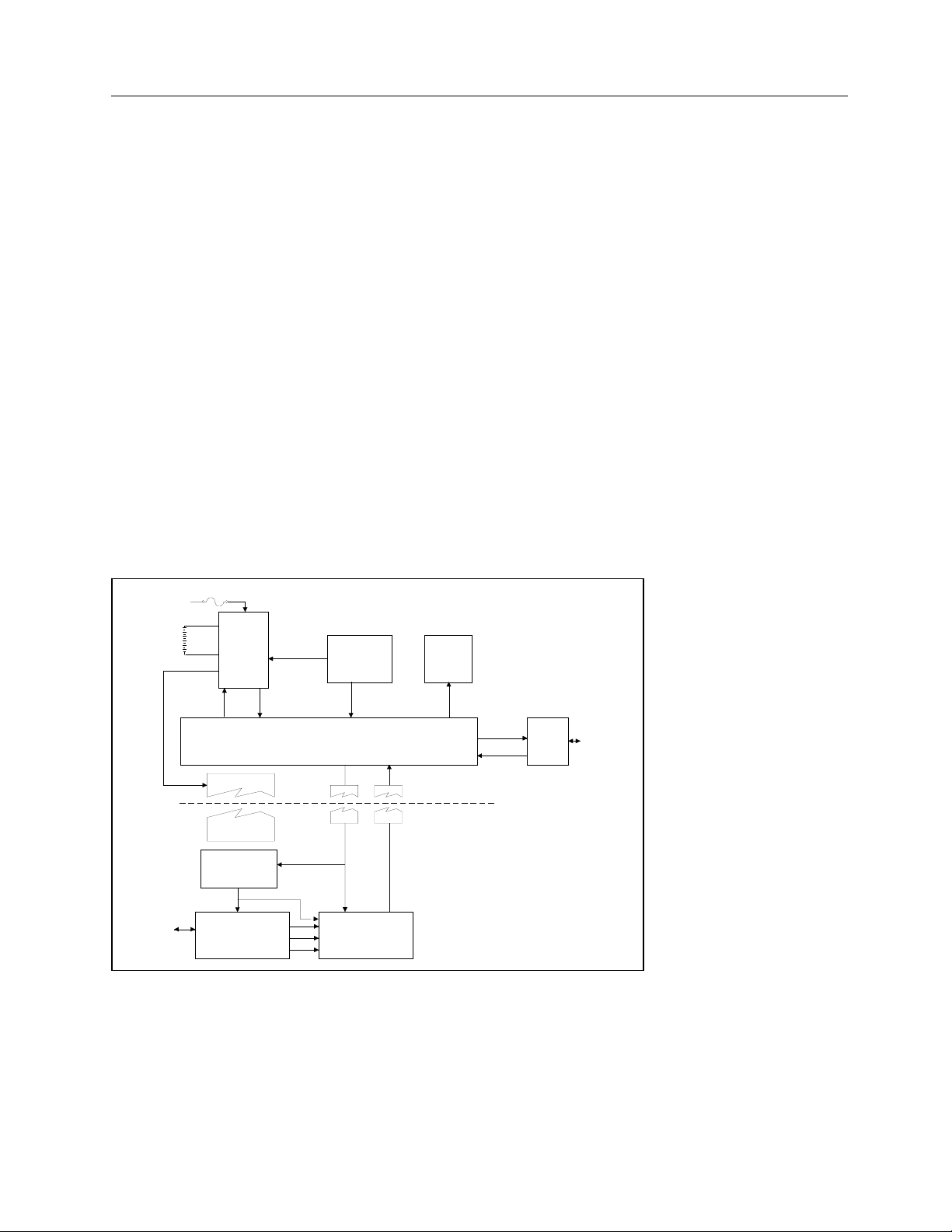
2.2 Functional Description
The Model 35040 Therapy Dosimeter is a portable instrument that measures charge and current.
Calibrated ion chamber factors convert charge and current to directly measure radiation dose and dose
rate in the user specified radiological units. The reading may be corrected for air density by the user
entering ambient temperature and barometric pressure readings. The electronic bias setting is selectable
from the front panel.
FUSE
AC Line
BATTERY
PACK
ION
CHAMBER
CONNECTOR
POWER
CONTROL
POWER
SUPPLY
ELECTRONIC
BIAS SUPPLY
BIAS
ELECTROMETER
BATTERY
STATUS
POWER
SWITCH
CONTACTS
BIAS CONTROL
FRONT PANEL
SWITCHES
PROCESSOR
MULTIPLEXER AND
A/D CONVERTER
SELECTION
SWITCH
CONTACTS
CONVERSION
CONTROL
CONVERSION
RESULTS
VFD
DISPLAY
SERIAL
COMM.
PORT
HIGH VOLTAGE ISOLATION
RS-232
COMPUTER
INTERFACE
CONNECTION
Figure 2-1. Hardware Block Diagram of the Model 35040 Therapy Dosimeter
2-1
Page 16

35040
Operators Manual
2.2.1 Power Supply
During operation, the instrument may be powered by line voltage in the range of 100 to 240 VAC or from
the internal 6 volt sealed lead acid battery for up to 8 hours. The power supply consists of a high
performance charger that continuously charges the battery whenever the instrument is plugged in. The
charger has three charging stages.
First stage: if the battery is fully discharged, the charger slowly recharges the battery until all cells in the
battery have a minimum charge level on them. The instrument will not operate until the battery has more
than the minimum charge on each cell. The first stage may be more than 18 hours depending on how
severely discharged the battery is.
Second stage: the charger enters a high charge rate that can restore more than 80% of the charge in 2 to
3 hours - even during normal operation. The battery voltage will range from 5.5 to 8.5 volts. The battery
current may be as high as 2.5 amps. After 3 hours of charging, the battery has enough charge for 8
hours of continuous operation.
Third stage: the charger enters a float charge stage that can be used indefinitely to maintain a full charge
on the battery without harm. The battery voltage is approximately 7 volts. The current will range from 0.5
to 0.01 amps. The lower the current, the closer the battery is to full capacity. For additional information
on care of the battery, see Section 3.8.
When operating from batteries, the battery current will be negative. The battery voltage will range from
6.5 volts to 5.4 volts. There are two automatic mechanisms to prevent excessive discharge of the battery.
If the voltage drops below 5.9 volts, a low battery annunciator (LoBat) is displayed on the front panel.
Less than 30 minutes of operating time are left. When the voltage drops to 5.4 volts, the firmware
automatically turns off the instrument. The hardware will turn off the power if the voltage drops below 5.4
volts.
The AC Power Line is fused as it enters the instrument with two fuses. These external fuses may be
replaced by the user (see Section 4.6 for details).
2.2.2 Front Panel
Pressing the power switch, an isolated, momentary-contact switch, once turns the power on. Pressing it
again turns the power off. At least 5 seconds should elapse after turning the power off to let the internal
parts reset before trying to turn power back on. The other keys, a matrix of 8 open contact membrane
switches, are scanned when any key closure is detected. The key code is stored until it is used. The four
line by twenty-character vacuum fluorescent display is easy to read over a wide range of lighting
conditions.
2.2.3 MicroController
A Motorola processor controls the instrument. The operating program is stored in EPROM. RAM is used
for volatile storage. Calibration parameters (gains and offsets) and customization parameters (ion
chamber calibration factors, pressure, and temperature units, bias settings) are stored in EEPROM. Each
time the instrument is turned off, all front panel settings are stored in a small portion of the EEPROM.
The settings are restored when the instrument is turned on.
2.2.4 Serial Communications Port
The serial port is configured as an RS-232C data communications device (DCE) running at 9600 baud, 8
bits, no parity, and 1 stop bit. The protocol uses XON/XOFF handshaking. This port is used for factory
calibration and testing, for calibration, for customization, and for remote control/data acquisition.
Inadvertent changes of the calibration or customization parameters are prevented by use of a three-step
sequence.
2-2
Page 17

Theory of Operation
Functional Description
2
2.2.5 Electrometer
The electrometer is a single range, resettable, integrating amplifier. The high speed solid state reset is
activated either by the operator pressing the RESET/MEASURE button or automatically when the
instrument detects the end of an exposure. Errors resulting from temperature drift of the components and
from dielectric absorption are dynamically corrected by the controlling firmware.
2.2.6 Bias Supply
The Model 35040 Therapy Dosimeter has a fully regulated electronic bias supply. The user may specify
up to 11 settings within the range -500.0 to +500.0 volts, in any order, during customization of the
instrument. Typical settings are +300.0, +150.0, 0, -150.0, and -300.0 volts, which conform to the
recommendations of the American Association of Physicists in Medicine Task Group 21 (AAPM TG21).
Other locality specific protocols can be accommodated within the 11 settings.
During operation, the bias supply output level is periodically measured by the A/D through a resistive
divider. If the output is more than ± 1.0 volt from the set voltage, an error message (LoBias, or HiBias)
will appear on the display. The bias supply has been designed to drive a capacitive load of less than
5000 pf.
CAUTION
Attaching a larger capacitance may create a
potential shock hazard.
For operator safety, the output of the bias supply is energy and current limited. Before attempting to
connect or disconnect an ion chamber, the operator should either set the bias voltage to 0 volts or turn off
the instrument. Setting the bias voltage to 0 volts pulls the bias to a safe level within one second. The
output of the bias supply is de-energized at power down. De-energizing may take 15 to 30 seconds.
2.2.7 Multiplexer and A/D Converter
The output of the electrometer is sampled at approximately 20 times per second by an analog to digital
converter. The temperature of the electrometer is measured whenever the electrometer is reset. The
program uses the temperature measurement to correct for temperature-induced drift in the electrometer
components. The internal temperature may be different from the ambient temperature, especially during
the battery high charge rate stage.
2.3 Basic Operating Equations
The instrument makes extensive use of the microcontroller’s processing capabilities to directly implement
the operating equations. The variables used in the equations are detailed in the table below. The
equations in this section have measurement units enclosed in square brackets as a reminder of the
required units, e.g. [C] for Coulombs.
2-3
Page 18

35040
Operators Manual
Table 2-1. Description of Quantities
Quantity Description Units Comments
Air Density
ADCF
QExposure
QAccum
QAccum_previous
QElectrometer
Q
QScaleFactor
QOffset
I
IAvg
ICCF
ILeakage
IScaleFactor
RateMultiplier
T
Time
TOffset
QTimed
QTimed_Predicted
Correction
Factor
Charge during
exposure
Accumulated
Charge
Previous
Accumulated
Charge
Electrometer
Charge
Charge C Calibrated electrical charge.
Charge Scale
Factor
Charge
Leakage
Current A Calibrated electrical current.
Average
Current
Ion Chamber
Calibration
Factor
Leakage
Current
Current Scale
Factor
Rate Units
Multiplier
Q Sampling
Time
Effective Time
of Exposure
QOffset
Sampling Time
Timed Charge C
Predicted
Timed Charge
None
C
C
C
C Factory calibrated electrical charge.
C / C
C
A
Ion
Chamber
Calibration
Units
/ A or C
A
A / A
s
s The time corresponding to Q and I.
s
s The time corresponding to QOffset and ILeakage.
C
Calculated by instrument and depends on front panel
Temperature and Pressure settings.
Electrical charge delivered to readout in response to
radiation incident upon detector since the last
exposure.
The sum of all charge accumulated due to exposures
since the RESET/MEASURE button was last pressed.
The sum of all accumulated charge not including the
current exposure since the RESET/MEASURE button
was last pressed.
Calibrates the charge measured by the electrometer.
Viewed on a Test Function screen.
The electrical charge measured when no incident
radiation is present.
The constant electrical current required to accumulate
charge Q over time TStart to T.
Values are field programmable via Customization
Software.
The electrical current measured when no incident
radiation is present.
Calibrates the current. Viewed on a Test Function
screen.
Specifies the number of seconds the rate divisor is
equal to 1(s), 60(min), 3600(hr).
The time required to accumulate charge QExposure
with a constant electrical current IAvg.
The electrical charge delivered during the timer
interval.
The total amount of timed charge that should be
accumulated at the completion of the timer interval,
based on the observed delivery rate.
2-4
Page 19

Theory of Operation
I
ICCF
ADCF
r
×
×
T
T
Basic Operating Equations
2
Charge and Current Measurements
The instrument’s electrometer charge and current measurements are factory calibrated to a United States
National Institute for Standards and Technology (NIST) traceable standard. Governing regulatory
agencies or best of practice protocols may require that the instrument be calibrated by an independent
calibration agency. The calibration agency may install the correction factors (Q
the instrument read out directly as calibrated. These factors are viewable by the operator but may not be
changed or turned off. In almost all cases, the scaling factors will be nearly unity.
[C/C] [C] rScaleFactoerElectromet QQQ ×=
⎛
() ( )
⎜
I ×
=
⎜
() ( )
⎝
⎞
iQiQ
−−
1
⎟
⎟
iTiT
−−
1
⎠
[A/A] [C/s] rScaleFactoI
[s] conversionerelectrometoftimeT =
ScaleFactor
, I
ScaleFactor
) to make
Leakage Measurements
Leakage measurements (Q
compensation is enabled.
The leakage current is defined as the current present between exposures. The displayed leakage current
or dose rate value (3-1/2 digit) is updated at a rate of approximately one time per second and held during
an exposure. Extrapolated charge due to leakage current is nulled from the measurement. In order to do
this, a short-term history of the leakage current is necessary.
Offset
, I
Leakage
and T
) are only applicable when automatic leakage
Offset
When an exposure is not in progress and the absolute value of the current is less than the start threshold,
pressing the RESET/MEASURE button sets the leakage current I
of current measurements for determining I
least 10 seconds. The ion chamber, cables, and instrument should not be disturbed while making the
leakage measurement.
()
∑
I
Leakage
=
DoseRateLeakage
Offset = [s]
[C] OffsetOffset TQQ =
n
[A]
I
1
n
Leakage=×
[A] [Units/C] [s]
To get the “best” determination of I
Leakage.
to zero and starts the acquisition
Leakage
takes time, at
Leakage
RateMultiplie
2-5
Page 20
35040
−
(
−
×
Operators Manual
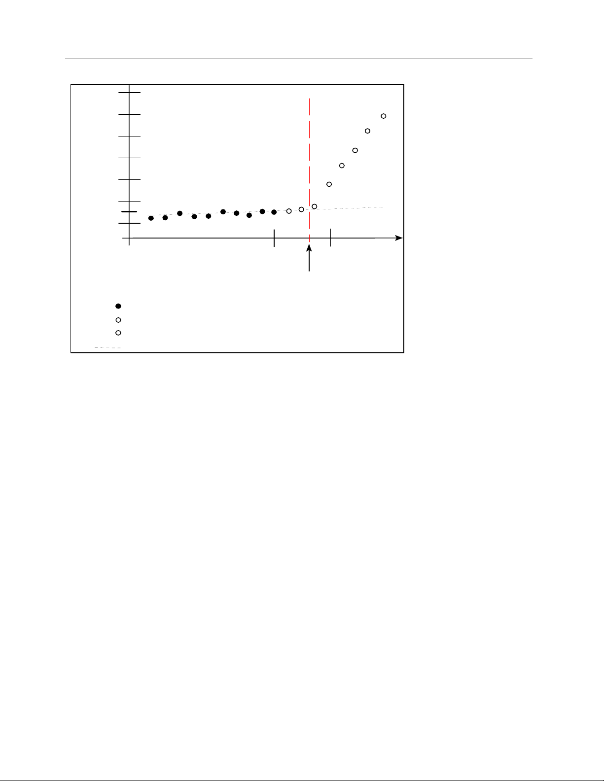
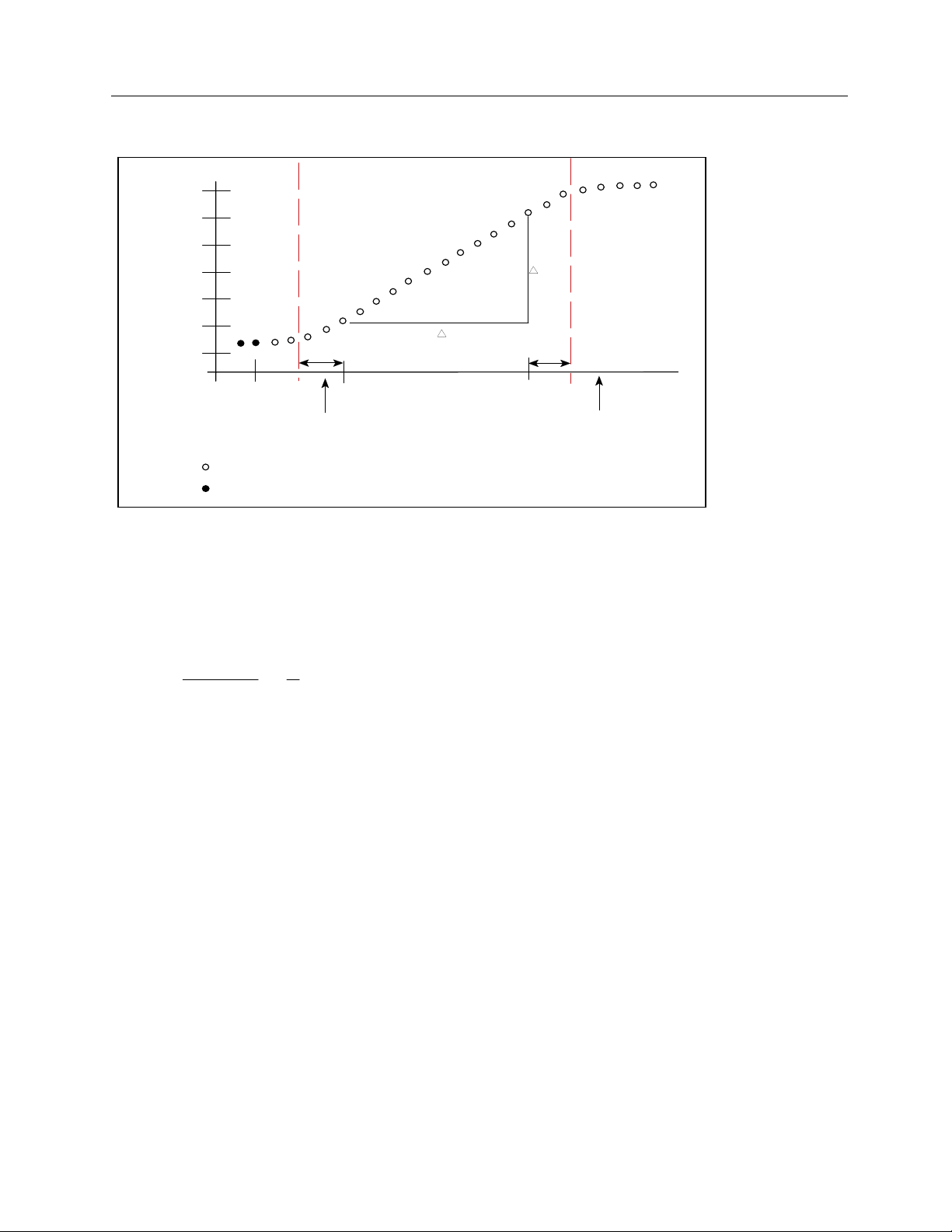
Charge
QOffset
X
X
X
0
TOffset
Start of Exposure
TStart
Time
- Charge samples in Leakage.
- Samples discarded.
X
- Charge samples in exposure.
- Extrapolated charge due to leakage current
Figure 2-2. Leakage Current and Start of Exposure
When automatic exposure detection is disabled (start and stop threshold set to 0.0 pA), there is no
correction for extrapolated charge due to leakage current. The dosimeter must be manually reset
between exposures and the leakage current kept as low as possible for best results.
Exposure Charge and Dose
The charge on the electrometer during an exposure is due to the incident radiation plus the charge that
was on the electrometer before the exposure plus the extrapolated charge due to any leakage currents in
the ion chamber, cables, or electrometer. To obtain only the charge due to the exposure, the instrument
employs the following equation:
)()
−−=
[s] [s] [A] [C] [C] OffsetLeakageOffsetExposure TTIQQQ
ADCFICCFQDose Exposure ××= [Units/C] [C]
The exposure charge variable Q
is set to zero at the start of an exposure either manually by
Exposure
pressing the RESET/MEASURE button or automatically if the start and stop thresholds are used. Over
the duration of the exposure, Q
and Dose are updated about once a second. The displayed
Exposure
measurement value (4-1/2 digit) is held following the exposure.
Timed Charge and Dose
This measurement accumulates charge only while the elapsed time is less than or equal to the timer
interval setting. The displayed value is held following the completion of the timer interval.
()()
×−−=
ADCFICCFQDose TimedTimed ××= [Units/C] [C]
2-6
[s] [s] [A] [C] [C] 12Leakage12Timed TTIQQQ
Page 21

Theory of Operation
×
×
×
×
×
×
×
Basic Operating Equations
represents the next sample of charge at time T1 following the activation of the timer. Q2 corresponds to
Q
1
the interpolated charge at time T
within the range: T
< T2 ≤ (T1 + Timer Interval Setting).
1
, where T2 is an integral number of seconds that is restricted to times
2
Predicted Timed Charge and Dose
This measurement extrapolates the timed charge (Q
accumulated at completion of the timer interval (i.e., TimerIntervalSetting) based on the rate of charge
delivery.
) at the elapsed time (T
Timed
) that should be
Elapsed
2
Q
ictedTimed_Pred
Elapsed
T
Timed
Q
At the conclusion of the timer interval (i.e., T
[s]
[C]
×=
valSettingTimerInter
×= [Units/C] [C]
Elapsed
[s]
ADCFICCFQDose ictedTimed_PredictedTimed_Pred
equals the TimerIntervalSetting), the predicted timed
charge and dose are equal to the predicted timed charge and dose, respectively.
Accumulated Charge and Dose
This measurement accumulates charge across multiple exposures. The displayed value is updated
during the exposure and held between exposures. It is reset to zero when the RESET/MEASURE button
is pressed while viewing a measurement screen.
[C] [C] _ ExposurepreviousAccumAccum QQQ +=
= [Units/C] [C]
ADCFICCFQDoseAccum Accum
Exposure Current and Rate
The current (3-1/2 digit) and dose rate displayed when the exposure is in progress are updated once per
second. The current and dose rate return to zero after the end of the exposure. The dose rate
measurement is displayed using the selected time base (seconds, minutes, or hours). If the start and
stop thresholds are set to zero, I
[A] [A] LeakageExposure III −=
×
Leakage
is zero.
[s] [Units/C] [A] = lierRateMultipADCFICCFIDoseRate Exposure
Average Current and Rate
The average current is calculated using the charge accumulated (
eliminate noise effects. The displayed value (4-/1/2 digit) is held following the exposure and reset at the
I
Avg
⎛
⎜
=
⎜
⎝
−
−
⎞
12
[C] [C]
QQ
⎟
⎟
[s][s]
12
TT
⎠
×
start of a subsequent exposure.
and Q2 are measured within the exposure at times T1 and T2 respectively. T1 is 1.33 seconds after the
Q
1
start of exposure. T
more than 3 seconds long. I
is 1.33 seconds before the end of exposure (see Figure 2-3). The exposure must be
2
is 0 if the exposure is less than 3 seconds.
Avg
Q
/
) during a portion of the exposure to
t
U
[s] [Units/C] [A] = lierRateMultipADCFICCFIgDoseRateAv Avg
2.3.1 Setting Thresholds
The instrument has capability to automatically detect the start and end of an exposure when the current
crosses given limits. Using automatic detection eliminates the sag in readings that occur due to leakage
2-7
Page 22

35040
×
Operators Manual
or dielectric absorption. The start and stop thresholds are set independently, but the stop threshold must
be less than the start threshold. The thresholds are settable in 0.1 pA increments from 0.0 pA to 9.9 pA.
In some test setups, it may be necessary to raise the thresholds to reliably detect an exposure in the
presence of a relatively large leakage current. Since the start threshold determines the minimum dose
rate, it may be necessary to lower the thresholds for some exposures.
××
[s] [Units/C] [A] = lierRateMultipADCFICCFIDoseRate
The minimum dose rate is
where I[A] is the start threshold setting.
When the start and stop thresholds are set to 0.0 pA, the automatic detection of start and end of exposure
is disabled. This effectively means that the instrument is measuring as if an exposure has been running
continuously. In this mode of operation, leakage current is not measured, the average current is
measured from the last time RESET/MEASURE was pressed, and charge will accumulate due to leakage
current.
NOTE
Thresholds other than those used by the calibration
agency may render inaccurate measurements.
2.3.2 Exposure Time
Historically, the determination of exposure time for 60Co has involved multiple exposures to eliminate the
effect of the shutter speed. By using the total charge and the average current for the exposure, the
effective exposure time can be determined using a single exposure. If the average current varies by more
than 10% during the exposure, this measurement is considered invalid and will be replaced by “INVALID.”
I
Avg
⎛
⎜
=
⎜
⎝
−
−
⎞
12
[C] [C]
QQ
⎟
⎟
[s][s]
12
TT
Time
⎠
⎛
[C]
Q
⎜
=
⎜
[A]
AvgI
⎝
⎞
⎟
⎟
⎠
The effective exposure time is derived from the total charge and the average current. In order to get
enough data points to accurately calculate the time, the exposure must be a minimum of 3 seconds. To
avoid artifacts at the start and end of exposure, the average current is calculated over the interval starting
1 1/3 seconds after the start is detected to 1 1/3 seconds before the end of exposure.
2-8
Page 23
Charge
X
X
X
X
0
TOffset
- Sampled charge data points in average current.
- Charge data points for leakage.
1.33s
T1
Time
Start of Exposure Detected
Figure 2-3. Average Current and Exposure Time
Theory of Operation
Basic Operating Equations
2
X
X X
X
X
X
X
Q
T
1.33s
T2
End of Exposure Detected
2.3.3 Air Density Correction Factor
ADCF
mmHg
760
⎛
=
⎜
P
⎝
T
⎛
⎞
×
⎜
⎟
T
⎝
⎠
The air density correction factor is used to correct dose and dose rate measurements for a vented ion
chamber.
where the pressure “P” is expressed in mmHg, the temperature “T” is in Kelvin, and the calibration
temperature “T
” is in Kelvin. The calibration temperature is either 20°C (293.15 K) or 22°C (295.15 K),
c
depending on that used by the calibration agency when calibrating the ion chamber. The calibration
temperature must be specified during customization. The ADCF is displayed on the bottom line of the Air
Density screen.
When the user has customized the Model 35040 Therapy Dosimeter to use other temperature and
pressure units, the corresponding values entered by the user at the instrument’s front panel are
automatically converted to mmHg and K before use in calculating the ADCF. The equations used for
these conversions are listed below. The abbreviation FSL stands for “from sea level.”
mm Hg = inch Hg x 25.4
mm Hg = 760 x (54,041 - feet FSL) / (54,041 + feetFSL)
mm Hg = 760 x (16,472 - metersFSL) / (16,472 + metersFSL)
mmHg = mbar x 0.75006
mmHg = hPa x 0.75006
⎞
⎟
c
⎠
K = (5 / 9) x (F - 32) + 273.15
K = C + 273.15
2-9
Page 24
35040
Operators Manual
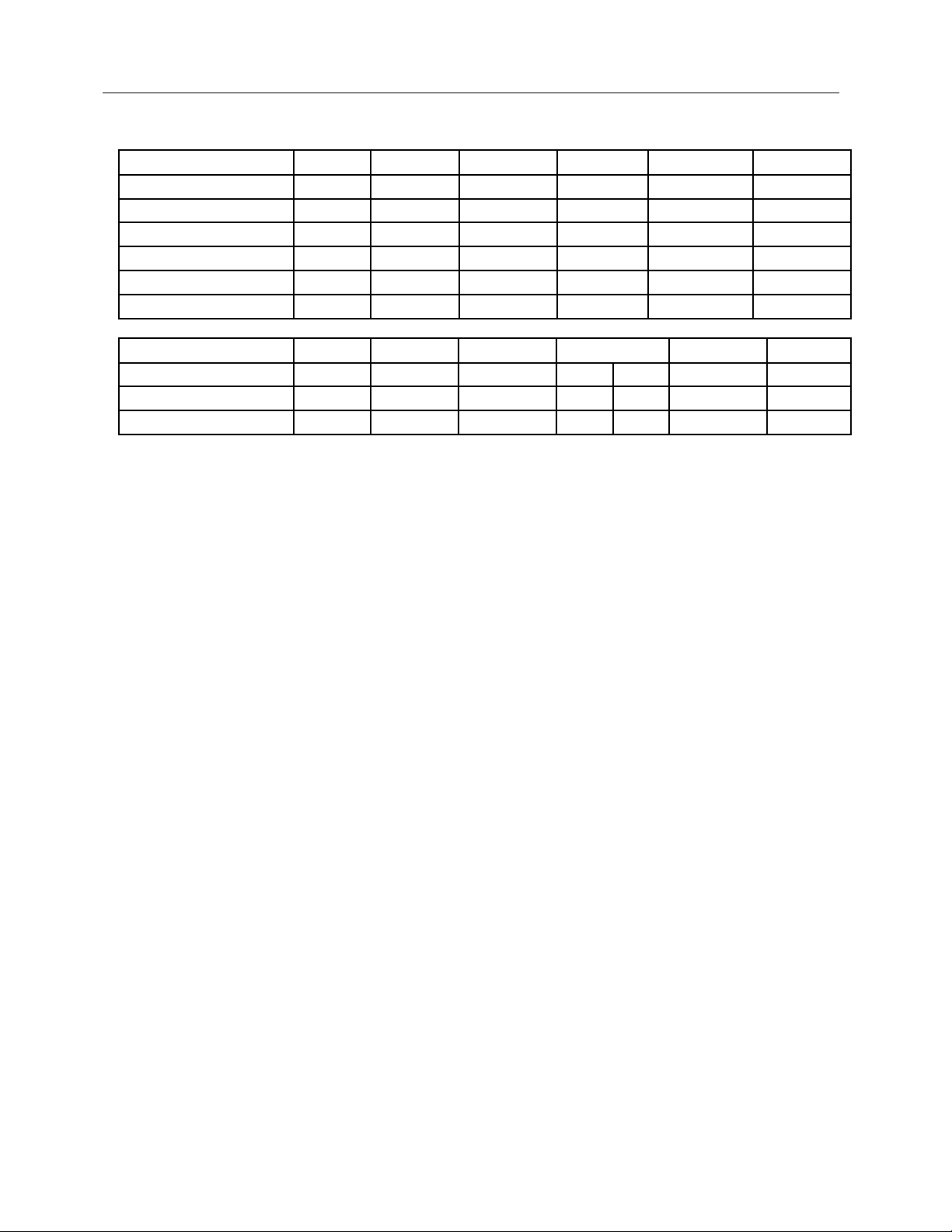
Table 2-2. Air Density Adjustment Ranges and Resolutions
Units Display Minimum Maximum Standard Resolution
% Error*
inches of mercury inHg 20.55 31.30 29.90 0.05 0.12
millimeters of mercury mmHg 522 795 760 1.0 0.10
altitude in feet ft -1200 10,000 0 25 0.07
altitude in meters m -360 3050 0 10 0.09
millibars mbar 697 1060 1013 1.0 0.07
hectoPascals hPa 697 1060 1013 1.0 0.07
Units Display Minimum Maximum Standard Resolution
% Error*
Fahrenheit F 32.0 122.0 71.6 68.0 0.5 0.05
Kelvin K 273.0 323.0 295.2 293.2 0.5 0.09
Celsius C 0.0 50.0 22.0 20.0 0.5 0.09
* The “% Error” column indicates the maximum amount of error that can occur due to the step resolution
of the pressure or temperature units.
2-10
Page 25
Operation
Setup
Section 3
Operation
3.1 Setup
Introduction
This section contains set-up and connection procedures for the Model 35040 Therapy Dosimeter.
The instrument is factory calibrated to measure charge (Coulombs) and current (Amperes). It is
recommended that the user customize the Model 35040 Therapy Dosimeter prior to its first use. This
customization may involve selecting the desired ion chamber calibration factor, temperature units,
pressure units, and bias voltages. Procedures for carrying out the customization are covered in Section
3.10.
3
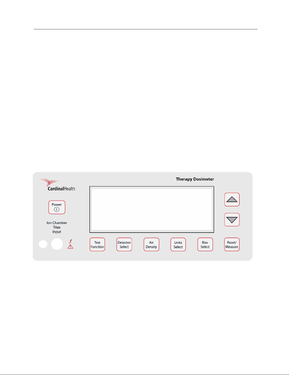
3.2 Front Panel Familiarization
Figure 3-1. The Model 35040 Therapy Dosimeter Front Panel
Triaxial Ion Chamber Input: This input accepts the current line of ion chambers from Fluke Biomedical,
various 0.6 cc, 0.3 cc, and 0.1 cc therapy ion chambers from other manufacturers, and Brachytherapy
well chambers. The front panel ion chamber input is wired in parallel with the rear panel ion chamber
input.
3-1
Page 26
35040
Operators Manual
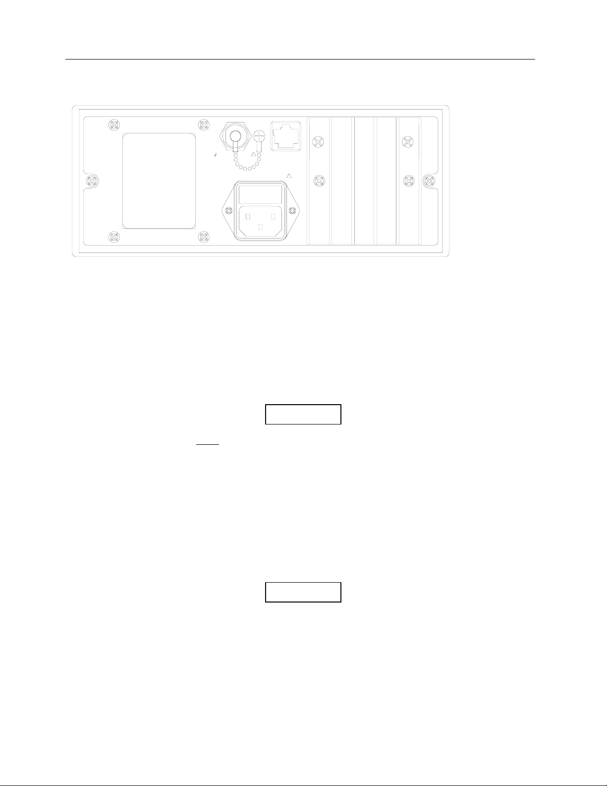
3.3 Rear Panel Familiarization
TRIAX
100-240V 50/60 Hz 50VA
!
COMPUTER
INTERFACE
RS-232
!
ION CHAMBER INPUT
Figure 3-2. The Model 35040 Therapy Dosimeter Rear Panel
RS-232 Receptacle (RJ-45 Style): The RS-232 Computer Interface is used for computer controlled
factory test, for calibration, for customization, and for remote control/data acquisition.
AC Line Power Receptacle: The AC line input range is 100 - 240 VAC (47 - 63 Hz). AC line voltage
within the specified range has no effect on any dosimeter measurements. The IEC 320/C13 style
receptacle permits worldwide operation by simply changing the line cord.
Triaxial Ion Chamber Input: This input is preferred in semi-permanent setups where the dosimeter is
stationary at the treatment console. The rear triaxial is wired in parallel with front panel input.
NOTE
Do NOT
attach ion chambers to both the front and
rear connectors at the same time. The signals will
be the summation of the two inputs and may result
in erroneous readings.
3.4 Powering The System
The Model 35040 Therapy Dosimeter may be operated from either line or battery power. The line
receptacle at the rear panel of the Model 35040 Therapy Dosimeter mates with a 3-wire line cord to
provide a connection to line voltage (high, neutral and earth ground).
When powering the Model 35040 Therapy Dosimeter from an
AC line, always use a 3-wire grounding type line cord such as
the one supplied with the dosimeter. In addition, only connect
the Model 35040 Therapy Dosimeter to an AC power outlet
employing a third wire safety ground. Failure to ground the
Model 35040 Therapy Dosimeter may result in personal injury
or death in the event of a short circuit or malfunction.
WARNING
3-2
Page 27
Operation
Powering the System
The Model 35040 Therapy Dosimeter operates on battery power for eight hours after a full charge. The
dosimeter can be recharged quickly, usually in two to three hours, even during instrument operation. A
low battery annunciator is displayed when 30 minutes or less of operation remains. When the battery
pack is fully discharged, the instrument automatically shuts off and will not operate until AC line power is
connected.
3
3.5 Power-Up Self-Test and Display Messages
When the instrument is powered up by pressing and releasing the POWER ON/OFF button, the following
sequence of screens will be displayed:
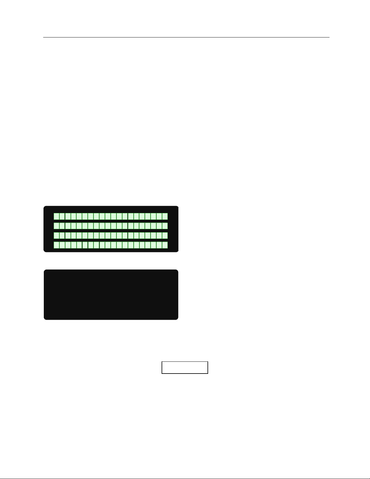
1. The Pixel Test screen lights up all the pixels on the screen (2-10 seconds).
2. Calibration information showing the calibration agency and the calibration date (2 seconds).
3. Firmware revision date (2 seconds).
4. Instrument bias, leakage, and battery levels.
During this opening screen sequence, pressing a front panel button will have no effect. The instrument
bias, leakage, and battery level screen will be the last screen displayed as shown below. At the
completion of the sequence, other functions may be selected.
See Section 3.9.4 for an explanation of the contents of each screen.
Figure 3-3. The Pixel Test Screen
ADC
Batt: 6.8 V +0.10 A
Leakage: 0.001 pA
IC Bias: 300.0V CEP
Figure 3-4. The Bias, Leakage, and Battery Voltage and Current
3.6 Ion Chamber Connector
Never connect a coaxial BNC type cable to the
Model 35040 Therapy Dosimeter’s triaxial ion
chamber input connectors. Doing so will damage
the ion chamber input connector.
CAUTION
3-3
Page 28

35040
Operators Manual
WARNING
Mating and unmating to this connector (or to the
other end of a cable already connected to it) should
be done only when the bias is set to 0 volts, or
when the instrument power is turned off. The
central pin and inner shield shell of the triaxial
connector are operated at the bias voltage above
the outer shell and instrument case. Although the
bias potential is energy and current limited, care
should be taken to avoid unnecessary and possibly
hazardous shocks.
The connector is a triaxial female with dust cap and chain. It connects to any low-noise triaxial male
cables. The NE 2571A 0.6 cc Farmer Ion Chamber and other ion chambers may be operated with the
Model 35040 Therapy Dosimeter.
The connector is mounted to avoid contaminating spills and dust. Putting its dust cap in place whenever
a cable is not connected will help assure long service with minimum leakage problems.
3.7 Basic Measurement Techniques
3.7.1 General Considerations
The dosimeter must be placed on a solid, non-vibrating surface. Both the dosimeter and the operator
must be outside the radiation field. Any cable movement will induce a current that may interfere with
proper measurements. You should wait ten seconds or more after moving the ion chamber, triaxial cable,
or disturbing another part of the high impedance circuit before taking a measurement.
3.7.2 Making Non-Timed Exposure Measurements
With Automatic Leakage Compensation Disabled
The instrument must be manually reset before each exposure when automatic leakage compensation is
disabled.
Procedure
• Hold RESET/MEASURE for one second just before making the exposure to reset the instrument.
Note that the instrument displays the “Rst” annunciator while the hardware is being reset.
• Wait for the reset to complete.
• Make the exposure.
The exposure measurements will be displayed but may drift due to leakage. Repeat this sequence for
every exposure.
With Automatic Leakage Compensation Enabled
In addition to compensating measurements for leakage, the instrument holds the exposure
measurements and automatically resets after each exposure when automatic leakage compensation is
enabled.
3-4
Page 29

Operation
Basic Measurement Techniques
Procedure:
• The annunciator line on the Measurement screen displays "WAIT System Not RDY" while the
instrument is acquiring the minimum number of samples required for leakage compensation. Wait
for this message to disappear.
• Wait for the leakage current to return to the nominal value.
• Make the exposure.
When the instrument senses that the exposure is over, it displays and holds the exposure measurements
and then resets the electrometer (refer to Section 3.9.7 for information on configuring the start and stop
thresholds). The exposure measurements are displayed until either the RESET/MEASURE button is held
for one second, the bias voltage or threshold changed, or another exposure is started.
3
3.7.3 Making Timed Exposure Measurements
The timer is available when any of the measurement displays contains a timed measurement. Refer to
Section 3.10 for information on customizing measurement displays.
Timer Setup
Procedure:
• Use the TEST FUNCTION button, along with the UP and DOWN arrows to display the Timer Setup
screen.
• To modify the timer setup, press the TEST FUNCTION button to display the "f" cursor at the timer
interval field and use the UP and DOWN arrows to select a timer interval from the programmed list.
(Refer to Section 3.10 for information on how to program the interval list.)
• Press the TEST FUNCTION button to advance the "f" cursor to the timer count mode field and use
the UP and DOWN arrow keys to select up (UP) or down (DOWN) for the count mode.
• Press the TEST FUNCTION button to advance the "f" cursor to the timer decimal places field and
use the UP and DOWN arrow keys to select zero (0) or one (1).
• Press the TEST FUNCTION button to hide the cursor and save any changes. Proceed to using the
timer, which is discussed next.
Timer Use
Procedure:
• Press the RESET/MEASURE button to show the Measurement screen if it is not displayed.
• To start or manually stop the timer, press the RESET/MEASURE button while the instrument is
updating other exposure measurements (e.g., charge and current). The instrument displays the
“Tmr” annunciator when the timer is running.
NOTE
The instrument will not permit the timer to be
started while leakage is being measured.
• Upon completion of the timer interval or if the instrument senses the exposure is over (applicable
when automatic leakage compensation is enabled), the instrument ceases updating the timed
measurements.
3-5
Page 30

35040
Operators Manual
NOTE
Use the predicted timed charge or dose
measurement to diagnose a problem at the onset of
a timed measurement for sources that deliver at a
constant exposure rate. If the predicted timed
measurement is drastically different from the
expected value, there is no reason to wait for the
complete timer interval to expire before
investigating the cause of the discrepancy.
NOTE
To differentiate the predicted and non-predicted
timed measurements, the instrument alternates the
display of time with a “PREDICT” indicator on the
predicted timed
measurement lines.
3.7.4 Using Other Ion Chambers
You may make measurements using electrical units of coulombs and amperes and manually calculate the
radiological values from known ion chamber and air density factors. Or you may use the Customization
software to add the new ion chamber’s description and calibration factor to the list available for
DETECTOR SELECT. See Section 3.10 for details.
3.8 Battery Care
To maximize both the life and the performance from the rechargeable battery, deep discharge should be
avoided. The battery will maintain peak performance through out the life of the product if the following
practices are adopted.
1. Store the instrument connected to the AC line power source if possible. This will maintain the
batteries at their full charge level and insure that the instrument is ready to go anytime it is needed.
2. If the instrument cannot be connected to AC line power during storage, fully recharge the batteries
at the beginning of the storage interval and store the instrument at 25°C or less if possible. For
extended storage, fully recharge the batteries at least annually to compensate for their selfdischarge characteristics. Decrease the time between maintenance recharges by one-half for each
10°C increase in the storage temperature above the 25°C baseline.
3. If possible, begin charging the batteries as soon as the “LoBat” annunciator appears and avoid
setting the automatic power down interval to a value greater than 15 minutes so that the batteries
will not become fully discharged if the instrument is left unattended.
4. Charge the batteries immediately if the instrument is allowed to operate to the 5.4 V automatic
power down level. This will avoid self-discharge to levels below which an extended recovery period
may be required.
5. If the instrument is used primarily from battery power, provide an extended charging period (24
hours or longer) for every 5 to 10 fast charge cycles.
The instrument will not operate when the battery voltage is below the 5.4 V automatic cutoff level. If the
battery voltage level is allowed to drop below this level due to self-discharge, an extended charge period
on the order of hours may be required to bring the voltage up to the 5.4 V level. During this period, the
3-6
Page 31

Operation
Battery Care
instrument will not be available for use. Depending upon the level of discharge, this period of
unavailability may be on the order of days, and in extreme cases the battery will be permanently
damaged.
3.9 Operation Instructions
This section contains detailed instructions on the front panel operation of the Model 35040 Therapy
Dosimeter. Please note that the display examples shown here correspond to a particular customization
set-up. Other customization set-ups will produce different results.
3.9.1 Front Panel Controls
Figure 3-5 shows the front panel of the Model 35040 Therapy Dosimeter. The front panel consists of a
triax connector, control buttons and a display. The following paragraphs describe the operation of each
3
control button and the corresponding display screens.
Figure 3-5. The Model 35040 Therapy Dosimeter Front Panel
Power
The POWER button toggles the system power on and off.
Test Function
The TEST FUNCTION button displays the Test Function screens. It is also used in setting the start and
stop exposure current thresholds.
• When the Test Function screen is not displayed, pressing the TEST FUNCTION button displays the
Test Function screen and the information/settings that were last viewed since power-up.
NOTE
The TEST FUNCTION screen provides access to
information and settings such as the firmware
revision, charge and current scale factors, battery
3-7
Page 32

35040
Operators Manual
and bias voltages, automatic leakage
compensation settings, and timer settings.
• When the Test Function screen is displayed, pressing the TEST FUNCTION button displays a
cursor that allows modification of the following settings:
- Enabling or disabling automatic leakage compensation or setting of the start and stop exposure
current thresholds
- Selecting the timer interval, count mode, and decimal places
- Specifying the effective exposure time presentation
Detector Select
The DETECTOR SELECT button displays the Detector Select screen.
Air Density
The AIR DENSITY button displays the Air Density screen. Subsequent presses advance the cursor
through the temperature, pressure, and air density correction on/off fields.
Units Select
The UNITS SELECT button displays the Units Select screen for selecting the rate divisor.
Bias Select
The BIAS SELECT button displays the Bias Select screen.
Reset/Measure
• When the Measurement screen is not displayed, pressing the RESET/MEASURE button displays
the Measurement screen and the Measurement display that was last viewed since power-up.
• When the Measurement screen is displayed:
- And when the instrument is performing exposure measurements, pressing the
RESET/MEASURE button toggles the timer
- Pressing and holding the RESET/MEASURE button for one second zeroes all exposure
measurements; the instrument also zeroes leakage measurements if leakage was being
measured
Up (S)
The function of the UP button depends on the screen displayed. It increases the temperature or pressure
setting. It toggles the state of the air density correction annunciator. For the Test Function and
Measurement screens, it displays the next information screen. It presents the next ion chamber for the
Detector Select screens. It increases the dose rate unit’s divisor. For setting the start and stop exposure
current thresholds, it increases the setting.
Down (T)
The function of the DOWN button depends on the screen displayed. It decreases the temperature or
pressure setting. It toggles the state of the air density correction annunciator. For the Test Function and
Measurement screens, it displays the previous screen. It presents the previous ion chamber for the
Detector Select screen. It decreases the dose rate unit’s divisor. For setting the start and stop exposure
current thresholds, it decreases the setting.
3.9.2 Powering Up the Model 35040 Therapy Dosimeter
Pressing the POWER button turns on the instrument. Initially, the instrument runs self-tests, restores the
ion chamber, temperature, pressure, air density correction status, exposure thresholds, and measurement
units to their previous values, and waits for the bias supply to stabilize.
3-8
Page 33

Operation
Operation Instructions
NOTE
When attempting to turn the instrument on, firmly
press the POWER button and hold for
approximately one second. Always allow several
seconds between retries.
During this self-test period, the Model 35040 Therapy Dosimeter displays a sequence of screens. The
first screen to appear after pressing the POWER button is the Pixel Test screen shown in Figure 3-6.
Figure 3-6. The Pixel Test Screen
The pixel test screen remains visible for two to ten seconds depending on the number of ion chamber
calibration factors in the instrument. It will be followed by the Calibration Identification screen shown in
Figure 3-11. After an additional two seconds, the display will change to the General Information Screen
shown in Figure 3-7. After two more seconds, the display will advance to the Bias and Battery Voltage
Test Screen shown in Figure 3-8. The bias voltage will take a few seconds to reach a stable value.
When the bias voltage is stable, the instrument is ready for use. While measurements may be made
immediately, the specified warm up time must elapse before specified accuracy is warranted.
3
3.9.3 Powering Down the Model 35040 Therapy Dosimeter
Pressing the POWER button turns the instrument off. As part of the power down sequence, the Model
35040 Therapy Dosimeter saves all of its front panel settings and is thus able to restore these settings
during the next power up sequence.
3.9.4 Using the TEST FUNCTION Button
Press the TEST FUNCTION button to display the Test Function screens, see Figure 3-7 to 3-11. Use the
UP and DOWN buttons to cycle through the Test Function screens. These screens contain information
about the instrument’s calibration, the calibration scale factors, firmware revision date, serial number,
leakage current, bias and battery condition, and optional text lines.
The top line of the display, shown in Figure 3-7, has annunciators for air density correction applied (ADC),
bias status (LoBias or HiBias), and battery status (LoBat). The firmware revision date, on the second line,
indicates the revision level of the controlling program in the instrument. The two optional text lines can be
customized using the Customization software.
ADC
FW Rev: 10JUN93 A
*Optional Text Line1
*Optional Text Line2
Figure 3-7. The Test Function Screen 1 - General Information
3-9
Page 34

35040
Operators Manual
Figure 3-8 shows the ion chamber bias voltage (IC Bias), the system leakage current (Leakage), and the
battery voltage and current. The bias voltage shown is 300.0 volts. The central electrode is positive
(CEP). The leakage current is 0.001 picoamps. The battery current is a small positive number, thus the
battery is charging and is almost fully charged.
ADC
Batt: 6.8 V +0.10 A
Leakage: 0.001 pA
IC Bias: 300.0 V CEP
Figure 3-8. The Test Function Screen 2 - Bias, Leakage, and Battery Voltage and Current
The battery current (shown in Figure 3-8), “+0.1 A”, is displayed to the right of the battery voltage, “6.8 V”.
A positive current value of up to 2.5 amperes indicates that the battery is being charged from the AC line.
As the battery approaches full charge, the current will decrease to near zero. A negative current value
will be shown when the instrument is operated from battery power. A negative current indicates the
actual current consumption of the instrument.
During a charging cycle, the battery voltage can range from 5.5 volts to 8.5 volts. After the battery
reaches its full charge, the charging circuit switches to float charge stage with a corresponding voltage of
approximately 7 volts. The unit will remain in the float charge stage as long as the instrument is attached
to an AC line. When the instrument is operated from battery power, the voltage will read between 6.5
volts (battery fully charged) and 5.4 volts (low battery shutdown voltage).
The two scale factors that appear in Figure 3-9 are those determined by a calibration agency.
QScaleFactor adjusts the charge. IScaleFactor adjusts the current. See Section 2.3 for details.
ADC
QScaleFactor=1.0000
IScaleFactor=1.0000
Figure 3-9. The Test Function Screen 3 - Calibration Scale Factors
Figure 3-10 shows the present settings for the start and stop threshold currents and the instantaneous
current measurement. See Section 3.9.5 for details.
ADC
Start Thres: 1.0pA
Stop Thres: 0.9pA
Current: 0.0pA
Figure 3-10. The Test Function Screen 4 - Leakage Threshold Screen
Figure 3-11 shows the automatic leakage compensation settings, which consist of the ALC status, start
and stop threshold currents, and the instantaneous current measurement. Refer to Section 3.9.5 for
details.
3-10
Page 35

Operation
Operation Instructions
3
ADC ALC
Start Thres: 1.0 pA
Stop Thres: 0.9 pA
Current: 0.0 pA
Figure 3-11. The Test Function Screen Showing the Automatic Leakage Compensation Settings
Figure 3-12 displays the settings for the timer interval, count mode, and decimal places. Refer to Section
3.9.6 for details.
ADC ALC
Interval: 60 s
Count: UP
Decimal Places: 0
Figure 3-12. The Test Function Screen Showing the Timer Settings
Figure 3-13 shows the display format setting for the effective exposure time, which determines the
presentation of the effective time on the Measurement screen.
ADC ALC
Exp Time: HR/MIN/SEC
Figure 3-13. The Test Function Screen Showing the Effective Exposure Time Display Setting
To change the effective time format setting, press the TEST FUNCTION button to show the "f" cursor
and use the UP and DOWN arrow buttons to select either seconds (SECONDS) or
hours/minutes/seconds (HR/MIN/SEC). Press the TEST FUNCTION button again to hide the cursor and
save the selection.
3.9.5 Automatic Leakage Compensation
Automatic compensation for leakage currents can be enabled and disabled from the front panel.
Automatic leakage compensation allows the instrument to “detect” when an exposure is in progress and
hold the final exposure measurement values between exposures.
The start threshold specifies the current necessary for the instrument to begin updating the exposure
measurements. The stop threshold must be smaller than the start threshold, and it indicates the minimum
current required for the exposure measurements to be updated once an exposure is detected. That is,
the instrument will cease updating the exposure measurements when the current drops below the stop
threshold and will return to measuring leakage.
NOTE
The instrument uses the start and stop threshold
settings to sense when an exposure is in progress.
3-11
Page 36

35040
Operators Manual
With the automatic leakage compensation settings displayed (Figure 3-14), press the TEST FUNCTION
button. The "f" cursor will appear to the left of the ALC annunciator. Use the UP and DOWN arrow
buttons to toggle the setting between on (ALC) and off (OFF).
With automatic leakage compensation enabled, press the TEST FUNCTION button to advance the "f"
cursor to the next field or exit Edit mode. When the cursor points to a threshold setting, use the UP and
DOWN arrow buttons to increment and decrement the value, respectively. Nominal values for the start
and stop thresholds are 1.3 and 1.2 pA, respectively. However, depending on the system leakage, other
values may be necessary.
When automatic leakage compensation is disabled, the annunciator displays off (OFF) (Figure 3-15), the
start and stop threshold settings cannot be changed and display Not Available (NA), as do the leakage
measurements.
ADC ALC
Start Thres: 1.0 pA
Stop Thres: 0.9 pA
Current: 0.0 pA
Figure 3-14. Automatic Leakage Compensation Enabled
ADC OFF
Start Thres: NA pA
Stop Thres: NA pA
Current: 0.0 pA
Figure 3-15. Automatic Leakage Compensation Disabled
NOTE
The instrument may reset all measurements when
the automatic leakage compensation parameters
are
changed.
NOTE
Disabling automatic leakage compensation prevents
automatic exposure detection and the measurement
of leakage current, and leakage measurements will
display Not Available (NA).
Figure 3-16 shows the name of the calibration agency and the date the instrument was calibrated. The
bottom three lines may be different on your instrument depending on what the calibration agency puts
here.
ADC
Calibrated by
Keithley RMD
Nov 15, 1993
Figure 3-16. The Test Function Screen 5 - Calibration Identification
3-12
Page 37

Operation
Operation Instructions
3
3.9.6 Timer Setup
The Test Function screen provides for configuring the timer interval, count mode, and decimal places (see
Figure 3-17).
With the timer settings displayed, press the TEST FUNCTION button. The "f" cursor will appear to the
left of the timer interval setting. Use the UP and DOWN arrow buttons to select a value from the user
customizable list. Refer to Section 3-10 for details on programming the timer intervals.
ADC ALC
Interval: 60 s
Count: UP
Decimal Places: 0
Figure 3-17. The Test Function Screen Showing the Timer Settings
Press the TEST FUNCTION button to advance the "f" cursor to the timer count mode field. Use the UP
and DOWN arrow buttons to toggle the setting between up (UP) and down (DOWN). For the up count
mode, the timer starts at zero (0) seconds and increments up to the timer interval setting. The down
count mode displays time starting from the timer interval setting and decrements to zero (0) seconds.
Press the TEST FUNCTION button to advance the "f" cursor to the timer decimal places setting. Use
the UP and DOWN arrow buttons to toggle the setting between zero (0) and one (1). Zero decimal places
displays time in whole seconds, while one decimal place displays time to a tenths of a second.
NOTE
Presently, the timer counts only in whole seconds.
3.9.7 Setting Thresholds
The automatic exposure detection start and stop threshold currents can be set from the front panel.
When the thresholds screen is displayed (Figure 3-10), press the TEST FUNCTION button. The “f”
cursor will appear to the left of the start threshold. Use the UP and DOWN arrow buttons to change the
setting. Press the TEST FUNCTION button to move the “f” cursor to the stop threshold setting. Use the
UP and DOWN arrow buttons to change the setting. Press the TEST FUNCTION button a third time to
return to viewing the rest of the test screens. It is recommended that the start threshold be set to 1.3 pA
and the stop threshold be set to 1.2 pA. Depending on the system leakage, other settings may be
necessary. See Section 2.3.1 for more details.
Changing the thresholds automatically zeroes all
measurements.
Setting the thresholds to 0.0 pA disables the
automatic exposure detection. This setting
prevents the measurement of leakage current.
“Leakage NA pA” on the display indicates the
leakage measurement is not available.
NOTE
NOTE
3-13
Page 38

35040
Operators Manual
3.9.8 Using the DETECTOR SELECT Button
Pressing the DETECTOR SELECT button displays the Detector Select screen, see Figure 3-18. This
screen displays information about the selected ion chamber calibration factor. An ion chamber consists of
two text lines and an ion chamber calibration factor (ICCF) with units. All ion chambers are entered and
can be modified via the Customization Software.
The “f” cursor points to the first description string of the selected chamber. Use the UP arrow to select
the next ion chamber and the DOWN arrow to select the previous ion chamber.
ADC
Farmer - S/N 12345
Co-60
ICCF=4.678E+09 R/C
Figure 3-18. The Detector Select Screen
The ion chamber calibration unit (R/C shown here) includes the radiological measurement unit (R). This
is the radiological unit that appears on the Measurement screens.
NOTE
The ion chamber’s calibration unit includes the
radiological measurement unit.
If you want radiological units that are not available, use the Customization software (see Section 3.10) to
enter a new ICCF with the appropriate units.
The descriptive text should contain enough information to let the operator correctly select an ICCF that is
appropriate for the measurement desired, e.g. energy, modality, build up, etc.
3.9.9 Using the AIR DENSITY Button
Pressing the AIR DENSITY button displays the Air Density screen, see Figures 3-19 and 3-20. This
screen contains the temperature value, pressure value, and Air Density Correction Factor (ADCF). Press
the AIR DENSITY button to advance the “f” cursor to the next field. To change the value or state of an
item at the “f” cursor, use the UP and DOWN arrows. The Model 35040 Therapy Dosimeter displays the
Air Density Correction (ADC) annunciator in the upper left-hand corner of all screens if the air density
correction is enabled, see Figure 3-19.
ADC
22.5 C 760 mmHg
ADCF = 1.002
Figure 3-19. The Air Density Screen With Air Density Corrections Enabled
To disable the air density correction, advance the “f” cursor to the ADC annunciator at the upper left of
the display. With the “f” cursor at this position, pressing the UP and DOWN keys will toggle the air
density correction on (ADC) and off (OFF).
3-14
Page 39

Operation
Operation Instructions
OFF
22.5 C 760 mmHg
ADCF = 1.000
Figure 3-20. The Air Density Screen With Air Density Corrections Disabled
Air density correction is only applied to dose or dose rate measurements such as, Roentgens, rads,
Grays, Sieverts, etc. These measures are dependent on correctly compensating for the mass of air in the
ion chamber. Electrical units (coulombs and amperes) are, by definition, insensitive to the mass of air in
the ion chamber.
3
3.9.10 Using the UNITS SELECT Button
Pressing the UNITS SELECT button displays the Units Select screen, see Figure 3-21. The radiological
units shown on the Units Select screen appear on the Measurement screens when displaying dose, dose
rate, accumulated dose, and average dose rate. This screen allows the radiological rate divisor (hr, min,
s) to be specified. The “f” cursor points to the radiological rate measurement unit. Press the UP arrow to
increase the rate divisor, and press the DOWN arrow to decrease the rate divisor.
ADC
dose unit: R
rate unit: R/min
Figure 3-21. The Units Select Screen for an Ion Chamber Calibrated for Dose Measurements
Ion chambers having dose rate calibration units will not have a rate divisor, e.g. Curies (Ci), becquerles
(Bq), or kerma (Sk). The dose rate units will be multiplied by seconds to produce an equivalent dose unit,
see Figure 3-22.
ADC
dose unit: Ci·s
rate unit: Ci
Figure 3-22. The Units Select Screen for an Ion Chamber Calibrated for Dose Rate Measurements
3.9.11 Using the BIAS SELECT Button
Pressing the BIAS SELECT button displays the Bias Select screen, see Figures 3-23 through 3-24. This
screen displays the bias setting and the bias voltage measured by the Model 35040 Therapy Dosimeter.
The “f” cursor points to the bias setting, expressed both as a voltage and as a percent of the maximum
voltage setting. The line below the bias setting indicates the bias polarity. The bottom line displays the
bias voltage measured by the instrument, and three letters to signify the bias polarity. When the central
electrode is positive, CEP is displayed to the right of the measured voltage. When the central electrode is
negative, CEN is displayed to the right of the measured voltage. (NOTE:
customizable; see Section 3-10.)
The bias settings are user
3-15
Page 40

35040
Operators Manual
ADC
Set:
300.0 V 100%
Central Electrde Pos
IC Bias: 300.0 V CEP
Figure 3-23. The Bias Select Screen With the Bias Set to a Positive Voltage
ADC
Set:
0.0 V 0%
Bias Off
IC Bias: 0.0 V OFF
Figure 3-24. The Bias Select Screen With the Bias Turned Off
ADC
Set:
-150.0 V -50%
Central Electrde Neg
IC Bias:-150.0 V CEN
Figure 3-25. The Bias Select Screen With the Bias Set to a Negative Voltage
In the example of Figures 3-23 to 3-25, the maximum voltage setting is 300.0 V. Thus, 300.0 V is 100%
of 300.0 V and -150.0 V is -50% of 300.0 V.
Use the UP and DOWN buttons to scroll through the customized bias settings. When the bias setting is
selected, wait for the bias voltage to match the selection before pressing the RESET/MEASURE button.
The top line of the display will read “WAIT Bias Not Ready” until the measured voltage matches the
selection. If the RESET/MEASURE button is pressed while the bias voltage is changing, the bias may be
set to the wrong voltage. While the bias voltage is changing, a current is produced that may cause an
“Internal Reset Error”, see Section 3.9.12.
Changing the bias setting automatically zeroes all
measurement readings.
To prevent an electrical shock, the Model 35040
Therapy Dosimeter bias should always be set to 0
volts or the instrument turned off when connecting
or disconnecting an ion chamber or triaxial cable.
NOTE
WARNING
3-16
Page 41

Operation
Operation Instructions
3
3.9.12 Using the RESET/MEASURE Button
The RESET/MEASURE button has dual functionality. If no Measurement screen is displayed, pressing
the RESET / MEASURE button displays one. When a Measurement Screen is displayed, pressing the
RESET/MEASURE button zeroes all measurement readings and causes the Model 35040 Therapy
Dosimeter to restart the measurement process.
Press the UP arrow to display the next Measurement screen. Press the DOWN arrow to display the
previous Measurement screen. The Measurement screens are user customizable via the Customization
software (see Section 3-10).
The Model 35040 Therapy Dosimeter is always collecting charge from the ion chamber, even when a
Measurement screen is not displayed.
The operator may view the Detector Select screen, the Air Density screen, the Test Function screen, or
the Units Select screen, make changes, and return to the Measurement screen to see the results.
Changing the bias voltage, the start threshold, or the stop threshold, automatically zeros all measurement
readings.
ADC
39.995 nC
659.8 pA
59.891 s
Figure 3-26. The Measurement Screen
Press RESET/MEASURE from the Measurement
screen to restart the leakage measurement process
after moving the triax cable connected to the Model
35040 Therapy Dosimeter.
The measurements have different visual cues to assist the operator in understanding the measurement.
If the instrument is trying to acquire enough data to make a measurement, the display area will be filled
with dashes. If the measurement is being actively updated, the decimal point will flash. When there was
inadequate time to get enough data for leakage compensation, a question mark is displayed to the left of
the measurement. If the measurement cannot be made due to the selected settings, the measurement is
replaced by “NA.” If the measurement has too much variation to be reliable, “INVALID” is substituted.
NOTE
3.9.13 Overranging Conditions
The Model 35040 Therapy Dosimeter displays an overrange indicator (“OVER”) when the electrometer’s
maximum limit has been exceeded (see Figure 3-27).
ADC
OVER nC
OVER pA
OVER s
Figure 3-27. The Measurement Screen With the Charge and Current Limits Exceeded Within the First
60 Seconds
3-17
Page 42

35040
Operators Manual
ADC
OVER nC
OVER pA
OVER min OVER s
ADC
Figure 3-28. The Measurement Screen With the
Charge and Current Limits Exceeded After the First
60 Seconds
Current Overrange
Reduce exposure and
Press RESET/MEASURE
Figure 3-29. The Measurement Overrange Screen
Table 3-1 specifies the conditions that cause the Model 35040 Therapy Dosimeter to display the
overrange indicator for a measurement.
Table 3-1. Overrange Conditions
Condition Values Overranged
charge > 2.4 μC
accumulated charge > 1.0000 C accumulated charge, accumulated dose
current > 100.0 nA all except leakage
time > 59 min 59 s effective exposure time
charge, accumulated charge, dose, accumulated dose, average
current, average dose rate, effective exposure time
3.9.14 Reset Error
Pressing the RESET /MEASURE button while on the Measurement Screen causes the Model 35040
Therapy Dosimeter to reset the electrometer, zero all readings, and restart the measurement process. If
an exposure starts during the reset operation, the instrument displays the reset error message (see
Figure 3-30).
ADC
Internal Reset Error
Press RESET/MEASURE
and Repeat Exposure
Figure 3-30. The Measurement Screen Showing a Reset Error
To remove the error condition, end the exposure, and press the RESET/MEASURE button. Wait a few
seconds and repeat the exposure.
3-18
Page 43

Operation
Operation Instructions
A reset error will not occur for ion chambers calibrated in dose rate units (i.e. Brachytherapy chambers)
since the measurement is primarily concerned with amps or dose rate.
3
3.9.15 Reset Error (With Automatic Leakage Compensation Enabled)
The following discussion is only applicable when automatic leakage compensation is enabled and the ion
chamber is calibrated in Coulombs.
Holding the RESET/MEASURE button while on the Measurement screen causes the Model 35040
Therapy Dosimeter to reset the electrometer, zero all readings, and restart the measurement process.
When an exposure is detected immediately following the reset that was not present prior to the reset, the
instrument displays the reset error message shown in Figure 3-31.
ADC ALC
Internal Reset Error
Press RESET/MEASURE
and Repeat Exposure
Figure 3-31. The Measurement screen showing the Reset Error message
To remove the error message, end the exposure and hold the RESET/MEASURE button. Wait a few
seconds for the instrument to complete the reset and repeat the exposure.
3.9.16 Annunciators
The top line of the display is dedicated to status annunciators. The Model 35040 Therapy Dosimeter
continuously monitors the ion chamber bias and battery voltages. If either one of these values is outside
the specified range, the Model 35040 displays an annunciator to indicate the error. Table 3-2 specifies
these annunciators and specifies the annunciators that may appear on the top line of the display.
Table 3-2. Annunciators
Annunciator Condition
??Bias
ADC
ALC
LoBat
LoBias
HiBias
OvAmps
Rst
Tmr
WAIT Bias Not Ready
WAIT System Not Rdy
Figure 3-32 illustrates the locations of some annunciators. The battery, bias, and overranged current
annunciators appear at the same location, and the instrument alternates the displaying of each
annunciator when more than one is applicable.
No bias measurement possible since the electrometer is not ready
Air density correction in use (only applicable to radiological
measurements)
Automatic leakage compensation enabled
Low Battery voltage
Low Bias voltage
High Bias voltage
Overranged current
Resetting electrometer
Timer in use
The dosimeter is setting the bias
The dosimeter is resetting the electrometer (only applicable when
automatic leakage compensation is enabled)
3-19
Page 44

35040
Operators Manual
ADC LoBias Tmr ALC
39.995 nC
659.8 pA
59.891 s
Figure 3-32. Annunciator positions
Table 3-2 lists the indicators the instrument uses to signal that a measurement quantity has not been
compensated for leakage or is not available due to the specified condition.
Table 3-2. Measurement Indicators and Conditions
Indicator Measurement Condition
Automatic leakage compensation is enabled, but
? (left of value) All Non-leakage
1
the exposure started before a leakage
measurement was available.
Automatic leakage compensation is enabled, but
-.--- Leakage
the exposure started before a leakage
measurement was available.
The calculated effective time is longer than the
INVALID Effective Time
actual exposure. This condition occurs when a
large amount of charge is injected at the
beginning of the exposure.
NA Leakage
The leakage measurement is not available since
automatic leakage compensation is disabled.
The quantity or one of its dependents has
OVER Non-leakage
1
exceeded the maximum value. Refer to Table 33 for more information.
1
All non-leakage measurements (e.g., charge, current, dose, rate, effective time, etc.)
Table 3-3 specifies the conditions that cause the Model 35040 Therapy Dosimeter to display an
overrange indicator (OVER) for a measurement quantity.
Table 3-3. Overrange Conditions
Condition Overranged Measurement
• charge
charge > 19.999 mC
• average current
• accumulated charge
• effective exposure time
accumulated charge > 1.0000 C
• accumulated charge
current > 1.000 μA • current
current > 1.200 μA • all non-leakage
1
time > 19,999.9 s
Includes radiological measurements derived from electrical measurements.
• effective exposure time
3-20
1
Page 45

Operation
Customization
3
3.10 Customization
3.10.1 Introduction
The Model 35040 Therapy Dosimeter is shipped with valid settings allowing you to make measurements
immediately. Should the need arise to change or modify any of the items described below, the
Customization software provides for customizing the Model 35040 Therapy Dosimeter to meet your
needs.
The basic features of the Customization software are its ease of use, on-screen help text, printer support,
and full customization capability for the Model 35040 Therapy Dosimeter.
The screens shown in this section represent the appearance of the Customization software running
Microsoft® Windows® 95/98 or later.
The Customization software has the following requirements:
• IBM Personal Computer or compatible
• EGA or VGA display
• CD drive
• Microsoft® Windows® 95/98 or later
• One serial port (COM1 thru COM4)
• One printer - recommended for printing out 35040 Customization reports
3.10.2 Installing/Uninstalling Customization Software
To install the 35040 Customization Software, insert the CD into your CD drive. The installation should
automatically start. If it does not, run setup.exe to start the installation. Administrator rights are required
to install the 35040 Customization Software on a Windows NT, Windows 2000 and Windows XP.
To remove the 35040 Customization Software from your hard disk, double click on "Add/Remove
Programs" in the Control Panel. On the "Install/Uninstall" tab, select "35040 Customization" in the list of
programs and click the "Add/Remove..." button. You will have to manually delete any "Dosimeter
Settings" text files (*.TXT) that you saved while using the Customization Software.
Refer to “Readme.txt” on the CD for the most current information on the 35040 Customization Software.
3.10.3 Connection to the Computer
To prepare the Model 35040 Therapy Dosimeter for customizing, insert the RS-232 cable into the
instrument. Connect the other end of the RS-232 cable to the computer serial port. Personal computers
have serial ports that are either 9 or 25-pin. Determine which you have and use the appropriate adapter
included with your Model 35040 Therapy Dosimeter. Use COM1 if it is available, otherwise use COM2,
COM3, or COM4. Turn on the Model 35040. Wait approximately five seconds and then start the
Customization software as described in Section 3.10.4.
3.10.4 Starting the Customization Software
Start the Customization software by selecting:
START | PROGRAMS | 35040 CUSTOMIZATION | 35040 CUSTOMIZATION
Refer to Fig. 3.10.33. The first time that the 35040 Customization Software is started, communication
with the Dosimeter will be tried over COM1. If COM1 is not available, an error message will be displayed
and the COM PORT indicator will turn red. If this is the case, use the COM PORT drop down list to select
the correct serial port. Subsequent startups will automatically connect to the serial port that you have
selected. If the customization forms have not been filled in with Dosimeter settings after starting the
3-21
Page 46

35040
Operators Manual
35040 Customization Software, verify that COM PORT indicator is green, and click on the UPLOAD
button.
We recommend that you print a copy of the customization report (Print) as your first step in the
customization process. This report contains all of the customization values and thus serves as a guide for
returning to the original settings should an operator keyboard error occur during the process. Additionally,
print a copy of the customization report as the final step in the customization process. Use this final
report to verify the new customization parameter values, and then save it in a safe place for future
reference. Reports can also be generated and saved as text files. Refer to Section 3.10.7, FILE | SAVE
AS and FILE | PRINT.
3.10.5 Downloading
The Customization software sends (downloads) information through the RS-232 link to the Model 35040
Therapy Dosimeter. This action happens automatically after you confirm the changes that you make to
any parameter. After downloading, the instrument sends back the information it received. The
Customization software compares the reply to what it sent down in order to verify that the screen display
and instrument contents are the same. In some cases, the downloading process may last several
seconds.
3.10.6 Menu Items and Controls
Refer to Figure 3-33 for the Menu Items and Controls that are at the top of each Customization form. The
operation of the controls is the same for all forms.
Figure 3-33. Menu Items and Controls
COM PORT Indicator
Green – PC port Initialized
Red - PC port not Initialized
Ion Chambers, Bias Settings, Special Items, Measurement Displays, or Timer Intervals
Selection of one of these five (5) menu items will bring up different forms for customizing the 35040
Dosimeter’s settings. Refer to the appropriate section below for a detailed description of each of the
forms and programming the Dosimeter’s settings.
COM PORT Drop Down List
Use the COM PORT drop down list to select the computer’s serial port used to communicate with the
35040 Dosimeter. To select a different serial port, click on the DOWN arrow key and select another port
from the drop down list by clicking on it. After the selection has been made, the serial port will be
initialized. If initialization is successful, the indicator to the right of the Com Port selection will turn
GREEN. If not, an error message will be displayed and the indicator will turn RED.
3-22
Page 47

Operation
Customization
3
CONNECT
Select CONNECT to force an initialization the computer’s serial port for use with the 35040 Customization
Software. Normally initialization is done automatically at the start of the 35040 Customization Software or
by selecting the serial port from the Com Port drop down list.
UPLOAD
Select UPLOAD to request the Dosimeter to send a listing of all the Customization Settings. When
depressed, all Customization forms are cleared and the Dosimeter’s latest settings are written to the
forms.
PRINT
Select PRINT to create a printed report of the customization items. The report will contain the current
state of all customization items within the Model 35040 Therapy Dosimeter. The report includes:
• All Ion Chambers including Title, Description, Calibration Factor, and Calibration Units
• All Special Items (Power Down Interval, Temperature and Pressure Units, Calibration Temperature,
and Optional Text Lines)
• All Measurement Displays printed as they would appear on the instrument’s front panel
• The Calibration Factors and Calibration Identification
• All the Bias Settings
CLOSE or FILE | CLOSE
Select CLOSE to terminate the Customization program. The program verifies the choice of Close before
terminating the program. Select “Yes” to exit; select “No” to return to the Customization program.
FILE | SAVE AS and FILE | PRINT
Select FILE | SAVE AS to generate a customization report and save it as a text file on the computer. A
standard Windows dialog box will be shown for naming the text file. Use FILE | PRINT to select a
customization report and then print it.
FILE | PRINT SETUP
Select FILE | PRINT SETUP to select a printer for printing the customization reports.
3.10.7 Ion Chambers
Figure 3-34 shows the Ion Chambers form. This form contains a List Box listing all of the ion chambers
available in the Model 35040 Therapy Dosimeter and a Parameter Display (titled Ion Chamber
Parameters) that displays the parameters for the selected ion chamber. At the bottom, there are four
buttons labeled APPEND, INSERT, DELETE, and STORE. Finally, a brief explanation of the controls on
the Ion Chamber’s form appears at the lower right. Use the vertical scroll bar to view the complete
description of the controls.
Within this form you may edit or remove any ion chamber in the instrument’s list. Also, you may add or
insert an ion chamber into the list.
3-23
Page 48

35040
Operators Manual
Figure 3-34. The Ion Chambers Form
EDIT
To modify existing ion chamber parameters, click twice with the mouse on a title within the Ion Chamber
List Box. A form titled “Program Ion Chamber” appears with the parameters of the selected Ion Chamber
and two buttons: OK and CANCEL. Refer to Figure 3-35. The following description of the Parameter
Editor may be followed when editing, appending, or inserting ion chamber parameters.
Figure 3-35. The Program Ion Chamber Form
To modify the Title, Description, or Calibration Factor, click on the desired text box and type in the new
text from the keyboard. To select different Calibration Units, click on the DOWN arrow key and select
another item from the drop down list by clicking on it.
3-24
Page 49

Operation
Customization
3
OK and CANCEL
When you complete your editing of ion chamber parameters, you may use OK or CANCEL to exit the
Parameter Editor. If you select CANCEL, all modifications are discarded and the original parameter
settings of the ion chamber remain. If you select OK, the ion chamber parameters (modified or not) are
sent to the instrument where they are stored for use during measurement modes.
NOTE
When Ion Chambers are edited, deleted, inserted,
or appended the List box background color will
change from ‘white’ to ‘yellow’ indicating that the
Dosimeter’s settings have been modified.
Permanent storage in the Dosimeter’s memory is
made only after depressing the STORE button or
by selecting one of the following menu items: BIAS
SETTINGS, SPECIAL ITEMS, MEASUREMENT
DISPLAYS, or TIMER INTERVALS. Storage in
memory may take up to 70 seconds.
APPEND
If you want to add an ion chamber to the end of the list of ion chambers, click on APPEND. The Program
Ion Chamber Form appears with the default text and values. Change the text and values to match those
of the ion chamber you are adding. Select OK to send the new ion chamber to the Model 35040 Therapy
Dosimeter; select CANCEL to discard the ion chamber and stop the append operation.
DELETE
If you want to delete an ion chamber, select it from the List Box. When you click on DELETE, you are
asked to confirm the deletion. Select YES to delete the ion chamber; select NO to stop the delete
operation.
INSERT
If you want to insert an ion chamber, select a position in the List Box ahead of which to insert a new ion
chamber. Click on INSERT. The Program Ion Chamber Form appears with the default text and values.
Change the text and values to match those of the ion chamber you are adding. Select OK to send the
new ion chamber to the Model 35040 Therapy Dosimeter; select CANCEL to discard the ion chamber and
stop the insert operation.
STORE
Click on STORE so that changes made to the instrument’s ion chamber list are stored permanently. This
process may last 70 seconds.
NOTE
If changes were made to the ion chamber list and
not stored permanently with the STORE button,
they are permanently stored when another
customization form is selected.
3.10.8 Special Items
Figure 3-36 shows the Special Items Form. This form contains the Power Down Interval, Temperature
and Pressure Units, Calibration Temperature, and two Optional Text lines. At the bottom, there are two
buttons labeled DOWNLOAD and CANCEL. At the right, a brief explanation of the focused item appears.
3-25
Page 50

35040
Operators Manual
Figure 3-36. The Special Items Menu (Calibration Temperature has focus)
To modify the Power Down Interval or Optional Text, click on the desired text box and type in the new text
from the keyboard.
To select the Calibration Temperature, or different Temperature or Pressure Units, click on the DOWN
arrow key and select another item from the drop down list by clicking on it.
NOTE
When a Special Item has been edited or changed,
its text box background color will change from
‘white’ to ‘yellow’. Permanent storage in the
Dosimeter’s memory is made only after depressing
the DOWNLOAD button.
DOWNLOAD and CANCEL
When you complete your editing of the Special Items, you may select DOWNLOAD or CANCEL. If you
select CANCEL, all modifications are discarded and the original settings of the Special Items return. If
you select DOWNLOAD, the Special Items (if modified) are sent to the instrument where they are stored
and used.
3-26
Page 51

Operation
Customization
3
3.10.9 Measurement Displays
The Model 35040 Therapy Dosimeter can contain up to sixteen (16) measurement displays, which are
viewed from the Measurement Displays Form. With this form you may customize the appearance of any
of the measurement displays. All screens must show an Annunciators Status Line (see Section 3.9.13)
on the first line of the display. You may choose what appears on the other three lines. Figure 3-37 shows
the Measurement Displays Form.
Figure 3-37. The Measurement Displays Form (right click the mouse on an item in the Display Line
List to show the format of the Display Line)
The display lines are grouped according to their function. The four groups are [Configuration] [Amps,
Coulombs, Volts] [Dose, Rate] and [Time]. Table 3-4 provides a listing of all the display lines available
for each group, along with a representation of the display line’s appearance on a measurement display.
Right click mouse on the Title of a Display Line (in the Display Line List) to view the format or Appearance
of the Measurement Display. Refer to Figure 3-37.
3-27
Page 52

35040
Operators Manual
Table 3-4. Available Display Lines
Group Title
Configuration
Amps, Coulombs, Volts
Dose, Rate
Time
Display Line
Appearance
(on a Measurement Display)
Blank Line
Air Density Setting ADCF = -.---
Temperature Pressure --.- C ---- hPa
Bias Setting Set: >+---.- V +---%
Firmware Revision FW Rev: 15OCT92 A
Time Interval Setting Interval: ---- s
IC Calibration Factor ICCF=1.234E+08 R/C
Optional Text 1 Optional Text Line 1
Optional Text 2 Optional Text Line 2
Battery Voltage Batt: -.- V +-.—A
Leakage Current Leakage: -.--- pA
Bias Voltage IC Bias: ---.- V CEP
Charge --.--- nC
Current ---.- pA
Accumulated Charge --.--- nC ACCUM
Average Current ---.— pA AVG
Timed Charge --.--- nC ---- s
Predicted Timed Charge --.--- nC PREDICT
Leakage Rate Leak: -.--- R/s
Dose --.--- nR
Rate ---.- pR/s
Accumulated Dose --.--- nR ACCUM
Average Rate ---.- pR/min AVG
Timed Dose --.--- nR ---- s
Predicted Timed Dose --.--- nR PREDICT
Time Interval Setting Interval: ---- s
Timed Charge --.--- nC ---- s
Predicted Time Chrg --.--- nC PREDICT
Timed Dose --.--- nR ---- s
Predicted Timed Dose --.--- nR PREDICT
Effective Exp. Time --.-- s
3-28
Page 53

Operation
Customization
3
Display Line Group Selection
Click on the Group’s DOWN arrow key and select another group from the drop down list by clicking on it.
Each group on the drop down list will bring up a different Display Line List. Refer to Table 3-4.
Selecting an Item and Placing It
Use the mouse to move an item from the Display Line List to a Display. With the mouse, place the mouse
cursor on the item. Press and hold the left key down. The item is now “grabbed” as indicated by the
rectangle shown around the display line. Drag the item using the mouse. When you have moved it to
display line you want, drop it by releasing the mouse button.
Changing a Line on a Display
To change a line on a Display, use the select and move operations described above to place an item on a
Display.
When an item replaces a line on a Display, the Customization software immediately sends the information
to the Model 35040 Therapy Dosimeter. In this manner, the Customization software always reflects the
current appearance of the Displays. Any line on any display may be changed as often as required.
Using the APPEND, DELETE, and INSERT Buttons
Within the Measurement Displays Form you may remove any Display in the instrument. Also, you may
add or insert a Display in the instrument. During these operations, different Displays will appear. A
maximum of four (4) displays can be viewed at any time. To see other Displays, use the vertical scroll bar
in the Display Frame to scroll up and down the Display list.
APPEND
If you want to add a Display to the end of the Displays, click on APPEND button. The Displays area of
the dialog box shows the new Display. You may customize the lines as described above. Append adds
one Display only.
NOTE
Upon selecting Append, the Customization
software tells the Model 35040 Therapy Dosimeter
to append a display with, initially, two Blank Lines
and a Charge measurement.
DELETE
If you want to remove a Display, click on the DELETE button. The Customization software prompts you
for the Display’s number. Enter a valid Display number and press OK (if you make an invalid entry, the
program beeps). The Display is removed. To abort the Delete operation, press CANCEL.
NOTE
Upon completing the deletion, the Customization
software tells the Model 35040 Therapy Dosimeter
to delete the Display you specified.
INSERT
If you want to insert a Display, click on the INSERT button. The Customization software prompts you for
the Display’s number ahead of which to insert a new Display. Enter a valid Display number and press OK
(if you make an invalid entry, the program beeps). The Display is inserted. You may customize the lines
as described above. To abort the Insert operation, press CANCEL.
3-29
Page 54

35040
Operators Manual
NOTE
Upon completing the insertion, the Customization
software tells the Model 35040 Therapy Dosimeter
to insert the Display you specified. Initially, the
inserted Display has two Blank Lines and a Charge
measurement.
3.10.10 Timer Intervals
The Model 35040 Therapy Dosimeter can contain up to twenty (20) timer interval settings, which are
programmed from the Timer Intervals Form.
Figure 3-38 shows the measurement Timer Intervals Form that contains the timer interval settings,
general editing information, and DOWNLOAD and CANCEL buttons.
Figure 3-38. The Timer Intervals Form
Select a field by clicking on it with the mouse. Enter an integral number of seconds for the timer interval
setting. When you select DOWNLOAD, the Customization software sends the timer interval settings to
the instrument. Select CANCEL to discard any changes and return to the Measurement menu.
NOTE
When a Timer Interval has been edited, its text box
background color will change from ‘white’ to
‘yellow’. Permanent storage in the Dosimeter’s
memory is made only after depressing the
DOWNLOAD button.
3-30
Page 55

Operation
Customization
The Model 35040 Therapy Dosimeter displays the timer intervals in the same order they are entered.
That is, it does not sort the timer interval settings. The UP arrow key displays the timer interval settings in
an increasing interval number order (e.g., Interval 1, Interval 2 … Interval 20), while the DOWN arrow key
presents the timer interval settings in a decreasing order. The instrument automatically skips any settings
that have a value of zero (0).
3
3.10.11 Bias Settings
To customize the bias voltage settings for your Model 35040 Therapy Dosimeter, select Bias Settings.
Figure 3-39 shows the Bias Settings that contains 11 bias setting fields, general editing information, and
DOWNLOAD and CANCEL buttons.
Figure 3-39. The Bias Settings Form
Select a field by clicking on it with the mouse. Enter a bias voltage setting between -500 and +500 V. If
you require zero (0) volts, you must enter 0 as a value. Blank settings are skipped in the instrument –
they are NOT interpreted as zero. When you select DOWNLOAD, the Customization software sends the
bias settings to the instrument. Select CANCEL to discard any change. Not all fields must have an entry;
the Model 35040 Therapy Dosimeter ignores blank fields. Bias settings may be entered in any order and
may be repeated.
NOTE
When a Bias Setting has been edited, its text box
background color will change from ‘white’ to
‘yellow’. Permanent storage in the Dosimeter’s
memory is made only after depressing the
DOWNLOAD button.
3-31
Page 56

35040
Operators Manual
When you press Bias Select on the Model 35040 Therapy Dosimeter front panel, the UP & DOWN keys
allow you to select the bias settings in the order you entered them in the Bias Settings dialog box.
3.10.12 Examples
The following examples describe many functions of the Customization program.
Editing an Ion Chamber
To change an ion chamber’s parameters, first select Ion Chambers from the menu.
1. Click twice on the ion chamber you want to modify.
2. Keyboard: To edit the Title, Description, or Calibration factor, start typing. The program places the
text into the focused area. Also, a blinking cursor indicates the position of the next character. To
select another parameter to edit, use the mouse to move the focus. To select different units, press
the DOWN arrow key to drop the list and to make a selection. Press OK to accept the new settings;
press CANCEL to retain the original settings.
Appending or Inserting an Ion Chamber
You may add or insert an ion chamber into the list of ion chambers by selecting APPEND or INSERT.
Append adds an ion chamber to the end of the list. Insert inserts an ion chamber ahead of the one
highlighted on the list.
APPEND
1. Click on the APPEND button.
2. The program enters the Edit mode where you may change the parameters as described in the first
example. Select OK to complete the APPEND operation; select CANCEL to abort it.
INSERT
1. Click on an ion chamber ahead of which to insert a new ion chamber.
2. Click on the INSERT button.
3. The program enters the Edit mode where you may change the parameters as described in the first
example. Select OK to complete the INSERT operation; select CANCEL to abort it.
To abort the Append or Insert operation, select CANCEL. If you select OK, the program sends the
information to the instrument along with instructions to append or insert the ion chamber information.
Deleting an Ion Chamber
Select DELETE to remove the highlighted ion chamber from the list. When you click on DELETE, you are
asked to confirm the deletion. Select YES to delete the ion chamber; select NO to stop the delete
operation.
Storing the Modified Ion Chamber Settings in the Dosimeter
Click on STORE so that changes made to the instrument’s ion chamber list are stored permanently. This
process may last 70 seconds.
NOTE
If changes were made to the ion chamber list and
not stored permanently with the STORE button,
they are permanently stored when another
customization form is selected.
Changing the Power Down Interval
To change the Power Down Interval, select Special Items from the Main menu. This example changes
the Power Down Interval to 15 minutes.
3-32
Page 57

Operation
Customization
1. Clicking on the Power Down Interval places the input focus there.
2. Keyboard: Enter 15 into the Edit Box.
2. Click on DOWNLOAD. The Customization software downloads the new Power Down Interval to the
model 35040 Therapy Dosimeter.
3
Changing the Pressure Units
To change the Pressure Units, select Special Items from the Main menu. This example changes the
Pressure Units to millibars.
1. Click on the DOWN arrow symbol of the Pressure Units Drop List.
2. Click on millibars.
3. Click on DOWNLOAD. The Customization software downloads the new Pressure Units to the
model 35040 Therapy Dosimeter.
Customizing a Measurement Display
To customize a Measurement Display, select Measurement Displays from the Main menu. This example
places the Battery Voltage readout on the third line of the second Display (Display 2).
1. Click on the down arrow symbol of the GROUP drop down list.
2. Click on “Amps, Coulombs, Volts”.
3. Move the mouse icon over “Battery Voltage” in the Display Line List box.
4. Press and hold the left key of the mouse and drag the ‘blank text box’ to the third line of Display 2.
Release the mouse button. The Customization software drops the Battery Voltage display text into
the third line of Display 2 and downloads the new contents of Display 2 to the Model 35040
Therapy Dosimeter.
To preview the display text, place the mouse icon over a display line description in the Display Line List
box and press and hold the right key of the mouse. The display text will appear on the bottom of the
Displays Programmed List box.
Appending a Display
This example shows how to add a Display to the end of all the Displays.
1. Click on the button labeled APPEND.
The Customization software appends a new Display and assigns it the next highest number. It also
downloads the append operation to the instrument. The new Display contains two Blank Lines and a
Charge measurement as a default. The Display appears immediately and you may add lines to it as
described in the first example.
Deleting a Display
This example shows how to remove Display 2 from the list of Displays.
1. Click on the button labeled DELETE.
2. The Customization software prompts you for the number of the Display to delete. Type 2 and press
OK. If CANCEL is selected, no display is deleted.
The Customization software deletes Display 2. All the Displays behind Display 2 move up in order. The
Customization software downloads the delete operation to the instrument.
Inserting a Display
This example shows how to insert a Display before Display 3.
1. Click on the button labeled INSERT.
3-33
Page 58

35040
Operators Manual
2. The Customization software prompts you to enter a Display number ahead of which to insert a new
Display. Type 3 and press ENTER.
The Customization software inserts a new Display ahead of Display 3. The Customization software
downloads the insert operation to the instrument. The new Display contains two Blank Lines and a
Charge measurement as a default. All the Displays behind Display 3 move down in order.
Changing a Bias Setting
To customize a Bias Setting, select Bias Settings from the Main menu. This example customizes the
second Bias Setting to 150 V.
1. Click on the Edit Box to the right of the Bias Setting 2 title.
2. Keyboard: Enter 150.
3. Click on DOWNLOAD. The Customization software downloads the new Bias Voltage Setting to the
model 35040 Therapy Dosimeter.
3.10.13 Errors
This section describes the error messages that may appear during the program’s operation. If an error
message appears, follow the instructions below to resolve the error. To remove the error message, use
the mouse or press a key. If you press a key and it has an associated operation, the operation executes.
Printing Error
A Printing Error occurs if the Customization software cannot initialize the printer. Check the computer
connection to the printer and try printing again.
Com Initialization Error
The selected serial COM port could not be initialized. Verify that the port selected is available and that it
is not being used by another program.
Serial Link Error
A Link Error occurs when the Customization software starts and cannot establish communication with the
instrument. If this happens, first verify that the Com Port Indicator is green signifying that the PC port has
been initialized. Next, verify that the serial port cable is connected from the PC to the 35040 Dosimeter
and that the Dosimeter is powered up.
Also try, cycling Dosimeter power, wait five (5) seconds, and click on the UPLOAD button.
Download Errors
When new customization settings are downloaded to the 35040 Dosimeter, the Dosimeter will send back
the new settings to verify that the data was properly received. The Customization software will verify that
the returned settings match what was transmitted to the instrument. If the match is correct, all data field
background colors that were yellow (indicating a changed parameter) will be changed back to white. If
there was a mismatch, the data field background color will remain yellow and an error message may also
be displayed. Repeat the download procedure if there was an error.
3-34
Page 59

Troubleshooting and Service
Introduction
4
Section 4
Troubleshooting and Service
The Model 35040 Therapy Dosimeter contains no
internal operator serviceable parts. Disassembly of
the unit could result in electrical shock.
Always select 0 volts bias or turn off the Model
35040 Therapy Dosimeter prior to connecting or
disconnecting the ion chamber. Failure to do so
may result in an electrical shock.
When powering the Model 35040 Therapy
Dosimeter from an AC line, always use a 3-wire
grounding type line cord such as the one supplied
with the dosimeter. In addition, only connect the
Model 35040 Therapy Dosimeter to an AC power
outlet employing a third wire safety ground.
NOTE
4.1 Introduction
This section outlines steps that the operator may take to identify and correct problems. It also gives
instructions on how to order replacement parts or arrange for service if necessary.
For the purpose of troubleshooting, some problems can be resolved by the operator in the field, even
though the Model 35040 Therapy Dosimeter contains no internal operator serviceable parts.
4.2 Troubleshooting
The dosimeter provides information that can be used in troubleshooting by the user. Troubleshooting has
been split into a list of symptoms and a set of decisions. The first section covers broad categories of
errors. It is organized as symptom, cause, and action blocks. The second section is organized as
decision trees.
A symptom is something that can be seen, heard, or felt. The most likely cause is stated, followed by
what action should be taken to correct the problem or isolate it. The last part of each block is a detailed
explanation.
4-1
Page 60

35040
Operators Manual
The decision trees of the second part are presented in text format. To use the decision tree, start with
statement number 1. The text may state one or more actions to be completed followed by a question.
Choose the most appropriate answer. Use the number after the answer to find the next statement.
Eventually, you will come to a statement that has an action and no question. This may refer you to
another section or provide a conclusion to the problem.
When “PROBLEM”: is the first part of the action, the problem has been identified. The exact wording of
the phrase should be used when reporting the problem to Fluke Biomedical’s Repair Coordinator.
Let’s walk through a likely problem. The instrument is running from the battery. The phrase “LoBat” is
blinking on the top line of the display. Look through the list of symptoms for the phrase “LoBat”. The
symptom-cause-action block states that the most likely cause is the battery voltage is less than 5.9 volts.
Many times the information in the cause may be enough to take corrective action. In this case though,
you are going to follow the suggested action. Turn to the decision tree titled Low Battery (see Section
4.4). The first statement asks if the instrument is plugged in. The instrument is not, so the answer is NO.
Proceed to statement 6. Statement 6 says to plug the instrument in and asks if the current is positive. All
parts of the instrument are operating normally, so the answer is YES. You proceed to statement 7.
Statement 7 states that the battery is charging. Since there is no question, you are done.
Symptom: Display does not light up when POWER is pressed.
Cause: The battery voltage may be very low.
Action: See Section 4.3.
Explanation: The instrument will not operate if the battery voltage is less than 5.4 volts. The battery
must be slowly charged to the 5.4 volt level by plugging the instrument in for up to 24
hours.
Symptom: “??Bias” annunciator displayed.
Cause: Signals from the high voltage side of the instrument are not valid.
Action: See Section 4.5.
Explanation: The electrometer has not been initialized properly or the data transfer across the high
voltage isolation has been interrupted. If the bias voltage is shorted by connecting or
disconnecting a cable while the bias is on, a high voltage spark may be generated which
can turn off some or all of the logic on the high voltage side of the instrument.
Symptom: “HiBias” annunciator displayed.
Cause: Bias is higher than the selected voltage by more than 1 volt.
Action: See Section 4.5.
Explanation: HiBias is a normal momentary indication when changing from one bias selection to the
next. It should only persist for a few seconds. This display is triggered when the
magnitude of the measured bias voltage exceeds the set point by more than 1 volt.
Symptom: “LoBias” annunciator displayed.
Cause: Bias is lower than the set point by more than 1 volt.
Action: See Section 4.5.
Explanation: LoBias is a normal momentary indication when changing from one bias setting to the
next. It should only persist for a few seconds. This display is triggered when the
magnitude of the measured bias voltage is less than the set point by more than 1 volt.
Symptom: “LoBat” annunciator displayed.
Cause: The battery voltage is 5.9 volts or less.
Action: See Section 4.4.
4-2
Page 61

Troubleshooting and Service
Troubleshooting
Explanation: The low battery annunciator is a reminder that while running on the battery, there is a
finite amount of energy available. For the battery in this instrument and the energy
consumption of the instrument, when the battery voltage drops below 5.9 volts there is
less than 30 minutes of operating time left.
Symptom: “Internal Reset Error” displayed.
Cause: Start of exposure detected during reset process.
Action: Stop the exposure. Press the RESET/MEASURE button. Wait for the “System Not RDY”
Explanation: The instrument measured a current above the start threshold while resetting the
ADC
Internal Reset Error
Press RESET/MEASURE
and Repeat Exposure
annunciator to extinguish. Start the exposure.
electrometer. It is assumed that the exposure was started while the reset was occurring.
If the exposure did start during the reset, some unknown amount of charge was lost. The
lost charge would lead to an incorrect reading.
4
Symptom: “Configuration Error” displayed.
Cause: The instrument has lost the calibration or customization data.
Action: Convert the configuration error number to a binary value using a program such as the
ADC
Configuration Error
Service Required
Error Number : 16
Windows® Calculator and use the table below to determine the extent of the problem.
For example, a configuration error of “18” corresponds to a binary value of “10010” (bits 5
and 2 set), which indicates that the customization for both the ion chamber and settings
are invalid.
Bit Description Action
1
2
3
4
5
6
Operator settings are
invalid.
Customization settings are
invalid.
Electrometer calibration
settings are invalid.
Bias calibration settings are
invalid.
Ion chamber customization
settings are invalid.
Ion chambers cannot be
read.
Select the proper settings
from the front panel.
Reinstall settings using the
Customization software.
Do NOT make
measurements. Return
instrument for repair.
Do NOT make
measurements. Return
instrument for repair.
Reinstall ion chambers using
the Customization software.
Return instrument for repair
to correct problem.
4-3
Page 62

35040
Operators Manual
7
8
9
Additional operator settings
are invalid.
Timer interval customization
settings are invalid.
Additional calibration
settings are invalid.
Select the proper settings
from the front panel.
Reinstall settings using the
Customization software.
Do NOT make
measurements. Return
instrument for repair.
Explanation: The instrument detects whether the stored parameters are valid at power-up. If the
parameters are invalid, it will affect one or more of the measurements. The operator may
restore some of the information either by selecting options from the front panel or by
running the customization software. Invalid calibration settings require a new calibration.
Follow the recommendations in the above table.
Symptom: "Current Overrange"
displayed.
ADC
Current Overrange
Reduce exposure and
Press RESET/MEASURE
Cause: The input current has exceeded the 1.200 uA limit.
Action: Stop the exposure. Change the setup to reduce the current.
Explanation: The instrument has a 1.000 uA limit on measurable current and will continue to measure
charge for currents up to 1.200 uA. The instrument can accept an input current up to 3
mA without damage to the instrument.
Symptom: “Current Overrange” displayed.
Cause: The input current has exceeded the 100 nA limit.
Action: Stop the exposure. Change the setup to reduce the current.
Explanation: The instrument has a 100 nA limit on measurable current. The instrument can accept an
input current up to 3 mA without damage to the instrument.
ADC
Current Overrange
Reduce exposure and
Press RESET/MEASURE
Symptom: Dashes displayed instead of digits.
Cause: No meaningful measurement could be obtained.
Action: Press the RESET/MEASURE button to reset the measurements.
Explanation: ICBias —.- V : the bias voltage measurement is unavailable due to invalid signals within
the instrument. This is a normal momentary condition when the instrument is powered
up.
Symptom: The bias voltage measurement changes by one digit.
4-4
Page 63

Troubleshooting and Service
Troubleshooting
Example: 299.9 to 300.0
Cause: Rounding error in measurement.
Action: None.
Explanation: The bias voltage is not actually changing. The control for the bias is in discrete steps.
The measurement is also in discrete steps. The control program may select a setting
that causes the measurement to be very near the transition between one measurement
step and the next.
4
4-5
Page 64

35040
Operators Manual
4.3 Display Will Not Light
1. Is the instrument connected to line voltage?
Disconnect the line cord. Check the fuse. (See Section 4.6.) Is the fuse
2.
filament intact?
3. Attach known operational appliance to outlet. Does the appliance work?
Connect instrument to AC line. Press the Power button.
4.
Did the display light up?
5. Is the battery current between +0.10 A and +3.00 A?
The fault has been cleared. The battery is charging. Leave the instrument
plugged in for at least 2 hours. When the battery is less than 5.4 volts and the
6.
instrument is running on battery, the instrument will turn itself off. This is to
protect the battery from becoming severely discharged.
Replace cord with known good cord or establish that the line cord is good. Is
7.
line cord good?
8. Was the battery low the last time the instrument was stored?
9. Has the instrument been plugged in for more than 24 hours?
10. PROBLEM: Instrument will not power up after 24 hours. See Section 4.10.
11. See Section 4.6.
12. Faulty Outlet. Use a different outlet.
13. See Section 4.2 to isolate problem.
14. ORDER: Proper line cord. See Section 4.9.
The battery may take more than 18 hours to recharge if the battery was in the
15.
low battery condition and was not recharged before storage. Leave the
instrument plugged in and try again in 18-24 hours.
16. PROBLEM: Instrument will not power up. See Section 4.10.
YES
NO
YES
NO
YES
NO
YES
NO
YES
NO
YES
NO
YES
NO
YES
NO
Go to
line:
2
4
3
11
4
12
5
7
6
13
8
14
9
16
10
15
4-6
Page 65

4.4 Low Battery
Troubleshooting and Service
Low Battery
4
Is the instrument connected to line voltage? Is the instrument connected to line
1.
voltage?
Turn the instrument off. Wait a few seconds. Turn the instrument on. A
2.
sequence of screens will appear. On the last screen, the battery voltage and
current are displayed. Is the battery current between +0.10 A and +3.00 A?
The battery is charging. Has the instrument been plugged in for more than 8
3.
hours?
4. Is the battery voltage greater than 5.9 volts?
5. PROBLEM: False battery low indication. See Section 4.10.
Connect AC line cord. If the display goes blank or stops updating, turn the
6.
instrument off. Wait a few seconds. Turn the instrument on. Is the battery
current between +0.10 A and +3.00 A?
The battery is charging. "LoBat" indicator will turn off when the battery voltage
7.
is above 5.9 volts.
8. Is the battery current between -1.00 A and -0.10 A?
Disconnect AC line cord from rear panel. Remove line fuses from rear panel
9.
fuse holder. Test the fuses with an ohmmeter. Are the fuses open circuited?
10. See Section 4.6.
Reinstall fuses. Reconnect AC line cord. Is the battery current between
11.
+0.10 A and +3.00 A?
12. The battery is charging.
13. Attach known operational appliance to outlet. Does the appliance work?
Instrument or line cord is faulty. Replace cord with known good cord or
14.
establish that the line cord is good. Is line cord good?
15. PROBLEM: Battery charger inoperative. See Section 4.10.
16. Outlet is faulty.
17. See Section 4.9. Order proper line cord.
PROBLEM: Low battery during trickle charge. Call Fluke Biomedical for
18.
Service.
Go to
line:
YES
NO
YES
NO
YES
NO
YES
NO
YES
NO
YES
NO
YES
NO
YES
NO
YES
NO
YES
NO
2
6
3
8
4
-5
--
7
8
9
18
10
11
12
13
14
16
15
17
4-7
Page 66

35040
Operators Manual
4.5 Bias Error
1. Is "??Bias" displayed?
2. Has the instrument been on for more than one minute?
Turn off the power. Wait 10 seconds. Turn on the power. Wait 1 minute. Is
3.
"??Bias" displayed?
4. PROBLEM: Electrometer fault. See Section 4.10.
Change the bias voltage to a different setting and then change back. Wait
5.
about 10 seconds. Is the error on the display?
Change the bias voltage to 0.0 V. Disconnect all triax cables. Cap the
6.
connectors. Change bias voltage to desired setting. Wait about 10 seconds.
Is the error on the display?
Change the bias voltage to 0.0 V. Examine the triax connectors on the
7.
instrument, both front and rear, for foreign matter. Is foreign matter present?
8. See Section 4.7.
9. Normal operation established.
10. Do you use a separate cable to connect the ion chamber to the instrument?
Change the bias voltage to 0.0 V. Connect only the cable to the instrument.
11.
Change the bias voltage to the desired setting. Wait about 10 seconds. Is the
error on the display?
12. PROBLEM: Bias fault in cable. See Section 4.10.
Change the bias voltage to 0.0 V. Connect the ion chamber. Change the bias
13.
voltage to the desired setting. Wait about 10 seconds. Is the error on the
display?
14. PROBLEM: Bias fault in instrument. See Section 4.10.
15. PROBLEM: Bias fault in ion chamber. See Section 4.10.
16. This message is displayed until the signals from the isolated side are valid.
Go to
line:
YES
NO
YES
NO
YES
NO
YES
NO
YES
NO
YES
NO
YES
NO
YES
NO
YES
NO
YES
NO
2
6
3
8
4
-5
--
7
8
9
18
10
11
12
13
14
16
15
17
4-8
Page 67

4.6 Line Fuse Replacement
Troubleshooting and Service
Line Fuse Replacement
4
NOTE
Disconnect the Model 35040 Therapy Dosimeter
from other equipment along with the AC line power
and turn off power before continuing with this
section.
1. Position the instrument on its display face.
Figure 4-1. Model 35040 Therapy Dosimeter Fuse Replacement
2. Remove the fuse drawer. With your fingernails, squeeze together the two ends of the fuse drawer
and pull it out of its slot.
3. Replace the fuses with P/N 38476.
WARNING
The use of different fuses may result in fire or
electrical shock in case of an internal fault.
4. Place the fuse drawer back into its slot. Press on the fuse drawer firmly until it snaps back into
place. Both sides of the fuse drawer should snap into place.
4-9
Page 68

35040
Operators Manual
NOTE
If fuses continue to fail - return the instrument for
repair.
4.7 Interface Connector Cleaning
WARNING
Select 0.0 V bias setting AND turn off the Model
35040 Therapy Dosimeter prior to cleaning the
interface connectors. Failure to do so may result in
an electrical shock.
The presence of dust or lint at the interface connectors can produce leakage currents that may have a
detrimental affect upon the accuracy of radiation measurements.
The ends of the interface cable may pick up dust and lint as the cable touches the floor during packing
and unpacking. Dirt may later be transferred to the interface connectors located on the Model 35040
Therapy Dosimeter during mating with the interface cable.
In some cases, the offending foreign matter may be removed by gently blowing across the connector with
dry air. Air containing moisture or other contaminants should be avoided. A suitable source of dry air is
available where camera accessories are sold. They are intended for use in cleaning fine and delicate
camera equipment. If this cleaning method fails to produce satisfactory results, then service will be
required.
A procedure for troubleshooting excessive leakage is given earlier in this section.
4.8 Cleaning The Instrument
To clean the exterior of the instrument, follow these steps:
1. Turn off the instrument and disconnect all input connectors.
2. Place the caps on both triax connectors.
3. Moisten a soft cleaning cloth with a solution of three parts water and one part liquid dishwashing
detergent.
Do not soak the cloth in the solution; you must not let the solution drip inside the instrument.
4. Use the moistened cloth to wipe the instrument’s exterior cover.
5. Let the instrument dry completely before using.
4.9 Replaceable Parts Information
Fluke Biomedical maintains a complete inventory of all normal replaceable parts (see Table 4-1). To
place an order, or to obtain information concerning replaceable parts, contact Fluke Biomedical at
440.248.9300.
4-10
Page 69

Troubleshooting and Service
Replaceable Parts Information
Table 4-1. Replaceable Parts List
Description Part Number
AC Line Cord (USA) CO-19
AC Line Cord (Europe CEE 7/7) 86512060
AC Line Cord (UK & Ireland) 86583000
AC Line Cord (Denmark) 86536041
AC Line Cord (Italy) 86531031
AC Line Cord (Switzerland) 86515050
Carrying Case 37777
Customization Kit 37886
DB-9 Female Connector 37616
7 foot RJ-45 Cable 105-260
Customization Software Disk 3.5" 37888
Handle 38439
Mounting Ear (Right) 428-328E
Mounting Ear (Left) 428-338B
Rubber Foot (Front) 070-80
Rear Foot 38600
Rubber Foot (Rear) FE-6
Dust Cap and Chain (BNC) 878-11-63
Dust Cap and Chain (TNC Optional) 414910-2
Fuse 38476
Fuse Drawer 018-304
4
4.10 Recalibration, Repair Information & Technical
Assistance
If your instrument needs recalibration or repair, we request that you contact Fluke Biomedical at
440.248.9300.
More information concerning the operation, application, or service of your instrument may be obtained
from the applications engineer at the previously listed numbers.
4.11 Warranty Information
Should your instrument require warranty service, contact Fluke Biomedical at 440.248.9300.
4-11
Page 70

35040
Operators Manual
(Blank Page)
Page 71

Sample Customization Reports
A.1 Sample Documents
Appendix
Sample Customization Reports
Appendix A
A
This section contains sample documents that the Customization Software can produce. It produced these
documents on a HP LaserJet
®
All of them contain the header “35040 THERAPY DOSIMETER”.
A-1
Page 72

35040
Operators Manual
A-2
Page 73

Appendix
Sample Customization Reports
A
A-3
Page 74

35040
Operators Manual
A-4
Page 75

Appendix
Sample Customization Reports
A
A-5
Page 76

35040
Operators Manual
(Blank page)
Page 77

Appendix
Features of Firmware Version “27JAN00” or Later B
Appendix B
Features of Firmware Version”27JAN00” or Later
B.1 Introduction
This addendum updates information provided in the Model 35040 Therapy Dosimeter Instruction Manual.
Particularly, the instrument now supports a measurement timer and extended charge and current ranges.
B.2 New Features
B.2.1 Overview
• Added timed charge, predicted timed charge, and the corresponding dose measurements
• Twenty (20) interval settings (1 to 9,999 s) selectable from the instrument’s front panel and user
programmable via the Customization software
• Ability to select the timer’s count mode and decimal places from the front panel
• Increased maximum charge from 2.4 μC to 19.999 mC
• Increased maximum current from 100 nA to 1.000 uA and auto-recovery for currents less than
1.200 μA
• ALC annunciator simplifies toggling of the automatic leakage compensation status and promotes
easy recognition of leakage compensation status
• Increased maximum effective time from “59 min 59.9 s” (3,599.9 s) to “5 h 33 min 19.9 s” (19,999.9
s)
B.2.2 Timed Measurements
The Model 35040 Therapy Dosimeter provides a timer for performing timed charge and dose
measurements. A typical application of the timer is for measuring brachytherapy sources. The
instrument supplies four timed measurement quantities, which may be added to any of the measurement
displays with the Customization software (refer to Section B.7).
While competing instruments may provide measurements similar to the timed charge or dose, the Model
35040 offers predicted timed measurements for superior diagnostic capabilities while measuring sources
delivering at a constant exposure rate (e.g., brachytherapy). The predicted timed measurements
extrapolate the amount of timed charge that should be collected at the completion of the interval, which
can reveal problems early in the measurement process versus waiting for the complete interval to expire.
B-1
Page 78

35040
Operators Manual
Refer to the following sections for details on the timed measurements:
• Section B.3.2, Making Timed Exposure Measurements, presents an overview on configuring and
using the timer.
• Section B.4.1, Front Panel Controls: RESET/MEASURE, discusses how to start and stop the timer
as well as zero measurements.
• Section B.4.4, Timer Setup, provides details on the timer configuration.
• Section B.5, THEORY OF OPERATION, specifies how the instrument performs timed
measurements.
• Section B.7, CUSTOMIZATION, provides information on customizing the measurement displays
and timer intervals.
B.2.3 Specifications Update
This section lists the specification changes with respect to the Model 35040 Therapy Dosimeter
Instruction Manual.
Charge Measurements
Range, Resolution, and Repeatability:
Full Scale Range Display Resolution
200.00 pC 0.01 pC 5
2.0000 nC 0.0001 nC 1.5
20.000 nC 0.001 nC 2.5
200.00 nC 0.01 nC 1
2.0000 μC 0.0001 μC
20.000 μC 0.001 μC
200.00 μC 0.01 μC
2.0000 mC 0.0001 mC 1
20.000 mC 0.001 mC 1
Repeatability
(± counts)
1
1
1
Timed Charge Measurements
Range and Resolution: Same as charge measurements.
Measurement Method: The timed charge measurement is derived by monitoring the charge integrated
over a time interval that begins with the activation of the timer. The timer automatically stops when the
elapsed time is equal to the timer interval setting or the exposure is over. Interpolation is used to
determine the charge at an integral number of seconds.
Measurement Accuracy: Same as charge measurements assuming that the rate of charge delivery does
not dramatically change within the interpolation window interval. Refer to Section B.5 for calculation
details.
Current Measurements
Range, Resolution, and Noise:
Full Scale Range Display Resolution
200.0 pA 0.1 pA 2
2.000 nA 0.001 nA 2
20.00 nA 0.01 nA 1
200.0 nA 0.1 nA 1
B-2
Noise
(± counts)
Page 79

1.000 μA 0.001 μA
Average Current Measurements
Range and Resolution:
Full Scale Range Display Resolution
200.00 pA 0.01 pA
2.0000 nA 0.0001 nA
20.000 nA 0.001 nA
200.00 nA 0.01 nA
1.0000 μA 0.0001 μA
Effective Exposure Time Measurements
Range and Resolution:
1
Appendix
New Features
B
Full Scale Range
Seconds Hours/Minutes/Seconds
59.99 s 59.99 s 0.01 s
19,999.9 s 5 h 33 min 19.9 s 0.1 s
Measurement Method: The effective exposure time value is calculated as the quotient of the charge and
average current measurement values. A minimum exposure duration of 3.5 seconds is required to
produce an effective exposure time measurement value.
Display Resolution
B.3 SETUP
B.3.1 Making Non-Timed Exposure Measurements
With Automatic Leakage Compensation Disabled
The instrument must be manually reset before each exposure when automatic leakage compensation is
disabled.
Procedure
• Hold RESET/MEASURE for one second just before making the exposure to reset the instrument.
Note that the instrument displays the “Rst” annunciator while the hardware is being reset.
• Wait for the reset to complete.
• Make the exposure.
The exposure measurements will be displayed but may drift due to leakage. Repeat this sequence for
every exposure.
With Automatic Leakage Compensation Enabled
In addition to compensating measurements for leakage, the instrument holds the exposure
measurements and automatically resets after each exposure when automatic leakage compensation is
enabled.
B-3
Page 80

35040
Operators Manual
Procedure
• The annunciator line on the Measurement screen displays "WAIT System Not RDY" while the
instrument is acquiring the minimum number of samples required for leakage compensation. Wait
for this message to disappear.
• Wait for the leakage current to return to the nominal value.
• Make the exposure.
When the instrument senses that the exposure is over, it displays and holds the exposure measurements
and then resets the electrometer (refer to Section B.4.3 for information on configuring the start and stop
thresholds). The exposure measurements are displayed until either the RESET/MEASURE button is held
for one second, the bias voltage or threshold changed, or another exposure is started.
B.3.2 Making Timed Exposure Measurements
The timer is available when any of the measurement displays contains a timed measurement. Refer to
Section B.7 for information on customizing measurement displays.
Timer Setup
Procedure
• Use the TEST FUNCTION button, along with the UP and DOWN arrows to display the Timer Setup
screen.
• To modify the timer setup, press the TEST FUNCTION button to display the "
interval field and use the UP and DOWN arrows to select a timer interval from the programmed list.
(Refer to Section B.7 for information on how to program the interval list.)
• Press the TEST FUNCTION button to advance the "
the UP and DOWN arrow keys to select up (UP) or down (DOWN) for the count mode.
• Press the TEST FUNCTION button to advance the "
use the UP and DOWN arrow keys to select zero (0) or one (1).
• Press the TEST FUNCTION button to hide the cursor and save any changes. Proceed to using the
timer, which is discussed next.
" cursor to the timer count mode field and use
" cursor to the timer decimal places field and
" cursor at the timer
Timer Use
Procedure
• Press the RESET/MEASURE button to show the Measurement screen if it is not displayed.
• To start or manually stop the timer, press the RESET/MEASURE button while the instrument is
updating other exposure measurements (e.g., charge and current). The instrument displays the
“Tmr” annunciator when the timer is running.
The instrument will not permit the timer to be
started while leakage is being measured.
• Upon completion of the timer interval or if the instrument senses the exposure is over (applicable
when automatic leakage compensation is enabled), the instrument ceases updating the timed
measurements.
Use the predicted timed charge or dose
measurement to diagnose a problem at the onset of
B-4
Page 81

a timed measurement for sources that deliver at a
constant exposure rate. If the predicted timed
measurement is drastically different from the
expected value, there is no reason to wait for the
complete timer interval to expire before
investigating the cause of the discrepancy.
To differentiate the predicted and non-predicted
timed measurements, the instrument alternates the
display of time with a “PREDICT” indicator on the
predicted timed measurement lines.
B.4 Operation Instructions
B.4.1 Front Panel Controls
Appendix
Setup
B
Test Function
• When the Test Function screen is not displayed, pressing the TEST FUNCTION button displays the
Test Function screen and the information/settings that were last viewed since power-up.
The TEST FUNCTION screen provides access to
information and settings such as the firmware
revision, charge and current scale factors, battery
and bias voltages, automatic leakage
compensation settings, and timer settings.
• When the Test Function screen is displayed, pressing the TEST FUNCTION button displays a
cursor that allows modification of the following settings:
- Enabling or disabling automatic leakage compensation or setting of the start and stop exposure
current thresholds
- Selecting the timer interval, count mode, and decimal places
- Specifying the effective exposure time presentation
RESET/MEASURE
• When the Measurement screen is not displayed, pressing the RESET/MEASURE button displays
the Measurement screen and the Measurement display that was last viewed since power-up.
• When the Measurement screen is displayed:
- And when the instrument is performing exposure measurements, pressing the
RESET/MEASURE button toggles the timer
- Pressing and holding the RESET/MEASURE button for one second zeroes all exposure
measurements; the instrument also zeroes leakage measurements if leakage was being
measured
B-5
Page 82

35040
Operators Manual
B.4.2 Using the Test Function Button
Figure B.1 shows the automatic leakage compensation settings, which consist of the ALC status, start
and stop threshold currents, and the instantaneous current measurement. Refer to Section B.4.3 for
details.
ADC ALC
Start Thres: 1.0 pA
Stop Thres: 0.9 pA
Current: 0.0 pA
Figure B-1. The Test Function screen showing the automatic leakage compensation settings
Figure B-2 displays the settings for the timer interval, count mode, and decimal places. Refer to Section
B.4.4 for details.
ADC ALC
Interval: 60 s
Count: UP
Decimal Places: 0
Figure B-2. The Test Function screen showing the timer settings
Figure B-3 shows the display format setting for the effective exposure time, which determines the
ADC ALC
Exp Time: HR/MIN/SEC
presentation of the effective time on the Measurement screen.
Figure B-3. The Test Function screen showing the effective exposure time display setting
To change the effective time format setting, press the TEST FUNCTION button to show the " " cursor
and use the UP and DOWN arrow buttons to select either seconds (SECONDS) or
hours/minutes/seconds (HR/MIN/SEC). Press the TEST FUNCTION button again to hide the cursor and
save the selection.
B.4.3 Automatic Leakage Compensation
Automatic compensation for leakage currents can be enabled and disabled from the front panel.
Automatic leakage compensation allows the instrument to “detect” when an exposure is in progress and
hold the final exposure measurement values between exposures.
The start threshold specifies the current necessary for the instrument to begin updating the exposure
measurements. The stop threshold must be smaller than the start threshold, and it indicates the minimum
current required for the exposure measurements to be updated once an exposure is detected. That is,
B-6
Page 83

Appendix
Operation Instructions
the instrument will cease updating the exposure measurements when the current drops below the stop
threshold and will return to measuring leakage.
The instrument uses the start and stop threshold
settings to sense when an exposure is in progress.
With the automatic leakage compensation settings displayed (Figure B-4), press the TEST FUNCTION
button. The "
buttons to toggle the setting between on (ALC) and off (OFF).
" cursor will appear to the left of the ALC annunciator. Use the UP and DOWN arrow
B
With automatic leakage compensation enabled, press the TEST FUNCTION button to advance the "
cursor to the next field or exit Edit mode. When the cursor points to a threshold setting, use the UP and
DOWN arrow buttons to increment and decrement the value, respectively. Nominal values for the start
and stop thresholds are 1.3 and 1.2 pA, respectively. However, depending on the system leakage, other
values may be necessary.
When automatic leakage compensation is disabled, the annunciator displays off (OFF) (Figure B-5), the
start and stop threshold settings cannot be changed and display Not Available (NA), as do the leakage
"
ADC ALC
Start Thres: 1.0 pA
Stop Thres: 0.9 pA
Current: 0.0 pA
measurements.
Figure B-4. Automatic Leakage Compensation Enabled
Figure B-5. Automatic Leakage Compensation Disabled
The instrument may reset all measurements when
ADC OFF
Start Thres: NA pA
Stop Thres: NA pA
Current: 0.0 pA
the automatic leakage compensation parameters
are changed.
Disabling automatic leakage compensation prevents
automatic exposure detection and the measurement
of leakage current, and leakage measurements will
display Not Available (NA).
B-7
Page 84

35040
Operators Manual
B.4.4 Timer Setup
The Test Function screen provides for configuring the timer interval, count mode, and decimal places (see
Figure B-6).
With the timer settings displayed, press the TEST FUNCTION button. The "
left of the timer interval setting. Use the UP and DOWN arrow buttons to select a value from the user
customizable list. Refer to Section B.7 for details on programming the timer intervals.
" cursor will appear to the
ADC ALC
Interval: 60 s
Count: UP
Decimal Places: 0
Figure B-6. The Test Function Screen Showing the Timer Settings
Press the TEST FUNCTION button to advance the "
and DOWN arrow buttons to toggle the setting between up (UP) and down (DOWN). For the up count
mode, the timer starts at zero (0) seconds and increments up to the timer interval setting. The down
count mode displays time starting from the timer interval setting and decrements to zero (0) seconds.
Press the TEST FUNCTION button to advance the "
the UP and DOWN arrow buttons to toggle the setting between zero (0) and one (1). Zero decimal places
displays time in whole seconds, while one decimal place displays time to a tenth of a second.
Presently, the timer counts only in whole seconds.
" cursor to the timer count mode field. Use the UP
" cursor to the timer decimal places setting. Use
B.4.5 Reset Error (with Automatic Leakage Compensation Enabled)
The following discussion is only applicable when automatic leakage compensation is enabled and the ion
chamber is calibrated in Coulombs.
Holding the RESET/MEASURE button while on the Measurement screen causes the Model 35040
Therapy Dosimeter to reset the electrometer, zero all readings, and restart the measurement process.
When an exposure is detected immediately following the reset that was not present prior to the reset, the
ADC ALC
Internal Reset Error
Press RESET/MEASURE
and Repeat Exposure
instrument displays the reset error message shown in Figure B-7.
Figure B-7. The Measurement Screen Showing the Reset Error Message
To remove the error message, end the exposure and hold the RESET/MEASURE button. Wait a few
seconds for the instrument to complete the reset and repeat the exposure.
B-8
Page 85

Appendix
Operation Instructions
B.4.6 Annunciators, Indicators, and Overrange Conditions
Table B-1 specifies the annunciators that may appear on the top line of the display.
Table B-1. Annunciators
Annunciator Condition
??Bias
ADC
ALC Automatic leakage compensation enabled
LoBat Low Battery voltage
LoBias Low Bias voltage
HiBias High Bias voltage
OvAmps Overranged current
Rst Resetting electrometer
Tmr Timer in use
WAIT Bias Not Ready The dosimeter is setting the bias
WAIT System Not Rdy The dosimeter is resetting the electrometer
Figure B-8 illustrates the locations of some annunciators. The battery, bias, and overranged current
annunciators appear at the same location, and the instrument alternates the displaying of each
annunciator when more than one is applicable.
No bias measurement possible since the
electrometer is not ready
Air density correction in use (only applicable to
radiological measurements)
(only applicable when automatic leakage
compensation is enabled)
B
ADC LoBias Tmr ALC
39.995 nC
659.8 pA
59.891 s
Figure B-8. Annunciator Positions
Table B-2 lists the indicators the instrument uses to signal that a measurement quantity has not been
compensated for leakage or is not available due to the specified condition.
Table B-2. Measurement Indicators and Conditions
Indicator Measurement Condition
? (left of value) All Non-leakage
-.--- Leakage Automatic leakage compensation is enabled, but the exposure
INVALID Effective Time The calculated effective time is longer than the actual
NA Leakage The leakage measurement is not available since automatic
OVER Non-leakage
1
All non-leakage measurements (e.g., charge, current, dose, rate, effective time, etc.)
1
Automatic leakage compensation is enabled, but the exposure
started before a leakage measurement was available.
started before a leakage measurement was available.
exposure. This condition occurs when a large amount of
charge is injected at the beginning of the exposure.
1
leakage compensation is disabled.
The quantity or one of its dependents has exceeded the
maximum value. Refer to Table B-3 for more information.
B-9
Page 86

35040
Operators Manual
Table B-3 specifies the conditions that cause the Model 35040 Therapy Dosimeter to display an
overrange indicator (OVER) for a measurement quantity.
Table B-3. Overrange Conditions
Condition Overranged Measurement
1
charge > 19.999 mC charge
average current
accumulated charge
effective exposure time
accumulated charge > 1.0000 C accumulated charge
current > 1.000 μA
current > 1.200 μA
current
all non-leakage
time > 19,999.9 s effective exposure time
1
Includes radiological measurements derived from electrical measurements.
B-10
Page 87

Appendix
−
×
Theory of Operation
B.5 Theory Of Operation
Basic Operating Equations
Quantity Description Units Comments
Q
Timed Charge C The electrical charge delivered during the timer
Timed
interval.
Q
Timed_Predicted
Leakage Measurements
Leakage measurements (Q
compensation is enabled.
Timed Charge and Dose
This measurement accumulates charge only while the elapsed time is less than or equal to the timer
interval setting. The displayed value is held following the completion of the timer interval.
Predicted
Timed Charge
Offset, ILeakage
C The total amount of timed charge that should be
accumulated at the completion of the timer
interval, based on the observed delivery rate.
and T
) are only applicable when automatic leakage
Offset
B
()()
×−−=
[s] [s] [A] [C] [C] 12Leakage12Timed TTIQQQ
ADCFICCFQDose TimedTimed ××= [Units/C] [C]
Q
represents the next sample of charge at time T1 following the activation of the timer. Q2 corresponds to
1
the interpolated charge at time T
within the range: T
< T2 ≤ (T1 + Timer Interval Setting).
1
, where T2 is an integral number of seconds that is restricted to times
2
Predicted Timed Charge and Dose
This measurement extrapolates the timed charge (Q
accumulated at completion of the timer interval (i.e., TimerIntervalSetting) based on the rate of charge
delivery.
Q
Q
ictedTimed_Pred
Timed
T
Elapsed
[C]
×=
[s]
valSettingTimerInter
[s]
×= [Units/C] [C]
At the conclusion of the timer interval (i.e., T
equals the TimerIntervalSetting), the predicted timed
Elapsed
charge and dose are equal to the predicted timed charge and dose, respectively.
) at the elapsed time (T
Timed
ADCFICCFQDose ictedTimed_PredictedTimed_Pred
) that should be
Elapsed
B-11
Page 88

35040
Operators Manual
B.6 Troubleshooting
This section outlines steps that the operator may take to identify and correct problems.
Symptom: "Configuration Error" displayed.
ADC
Configuration Error
Service Required
Error Number : 16
Cause: The instrument has lost the calibration or customization data.
Action: Convert the configuration error number to a binary value using a program such as the Windows
Calculator and use the table below to determine the extent of the problem. For example, a configuration
error of “18” corresponds to a binary value of “10010” (bits 5 and 2 set), which indicates that the
customization for both the ion chamber and settings are invalid.
Bit Description Action
1 Operator settings are
invalid.
2 Customization settings are
invalid.
3 Electrometer calibration
settings are invalid.
4 Bias calibration settings are
invalid.
5 Ion chamber customization
settings are invalid.
6 Ion chambers cannot be
read.
7 Additional operator settings
are invalid.
8 Timer interval customization
settings are invalid.
9 Additional calibration
settings are invalid.
Explanation: The instrument detects whether the stored parameters are valid at power-up. If the
parameters are invalid, it will affect one or more of the measurements. The operator may restore some of
the information either by selecting options from the front panel or by running the customization software.
Invalid calibration settings require a new calibration. Follow the recommendations in the above table.
Select the proper settings
from the front panel.
Reinstall settings using the
Customization software.
Do NOT make
measurements. Return
instrument for repair.
Do NOT make
measurements. Return
instrument for repair.
Reinstall ion chambers using
the Customization software.
Return instrument for repair
to correct problem.
Select the proper settings
from the front panel.
Reinstall settings using the
Customization software.
Do NOT make
measurements. Return
instrument for repair.
®
Symptom: "Current Overrange" displayed.
B-12
Page 89

Appendix
Operation Instructions
B
ADC
Current Overrange
Reduce exposure and
Press RESET/MEASURE
Cause: The input current has exceeded the 1.200 uA limit.
Action: Stop the exposure. Change the setup to reduce the current.
Explanation: The instrument has a 1.000 uA limit on measurable current and will continue to measure
charge for currents up to 1.200 uA. The instrument can accept an input current up to 3 mA without
damage to the instrument.
B.7 Customization
The screens shown in this section represent the appearance of the Customization software running within
a MS-DOS® window running on Windows® 95/98.
B.7.1 The Main Menu
The Main menu appears after customization information has been received from the Model 35040
Therapy Dosimeter. The menu items are Ion Chambers, Special Items, Measurement, Bias Settings,
Print, and Exit.
B.7.2 The Measurement Menu
The Measurement menu provides items Displays, Timer Intervals, and Quit. Select Displays to view the
Measurement Displays, Timer Intervals to view the Measurement Timer Intervals, or Quit to return to the
Main menu.
Measurement Displays
The Model 35040 Therapy Dosimeter can contain up to sixteen (16) measurement displays, which are
viewed from the Measurement screen. From the Measurement Displays section of the Customization
software, you may customize the appearance of any of the measurement displays. All measurement
displays must show the annunciators on the first line. You may choose what appears on the other three
lines
B-13
Page 90

35040
Operators Manual
Figure B-9 shows the Measurement Displays dialog box.
Figure B-9. The Measurement Displays Dialog Box (shown with the rotating rack having focus)
The display lines are grouped within the Rotating Rack according to their function. The groups consist of
“Configuration,” “Amps, Coulombs, Volts,” “Dose, Rate,” and “Time.” Table B-4 provides a listing of all the
display lines available for each group, along with a representation of the display line’s appearance on a
measurement display. Refer to the Model 35040 Therapy Dosimeter Instruction Manual for general
information on how to use the CLOSE, APPEND, DELETE, and INSERT buttons and move a display line
to a measurement display.
B-14
Page 91

Appendix
B
Table B-4. Available Display Lines
Display Line
Group
(on the Rotating Rack)
Configuration
Amps, Coulombs, Volts
Dose, Rate
Time
Blank Line
Air Density Setting ADCF = -.---
Temperature Pressure --.- C ---- hPa
Bias Setting Set: >+---.- V +---%
Firmware Revision FW Rev: 15OCT92 A
Time Interval Setting Interval: ---- s
IC Calibration Factor ICCF=1.234E+08 R/C
Optional Text 1 Optional Text Line 1
Optional Text 2 Optional Text Line 2
Battery Voltage Batt: -.- V +-.—A
Leakage Current Leakage: -.--- pA
Bias Voltage IC Bias: ---.- V CEP
Charge --.--- nC
Current ---.- pA
Accumulated Charge --.--- nC ACCUM
Average Current ---.— pA AVG
Timed Charge --.--- nC ---- s
Predicted Timed Charge --.--- nC PREDICT
Leakage Rate Leak: -.--- R/s
Dose --.--- nR
Rate ---.- pR/s
Accumulated Dose --.--- nR ACCUM
Average Rate ---.- pR/min AVG
Timed Dose --.--- nR ---- s
Predicted Timed Dose --.--- nR PREDICT
Time Interval Setting Interval: ---- s
Timed Charge --.--- nC ---- s
Predicted Time Chrg --.--- nC PREDICT
Timed Dose --.--- nR ---- s
Predicted Timed Dose --.--- nR PREDICT
Effective Exp. Time --.-- s
Title
(on the Rotating Rack)
Customization
Appearance
(on a Measurement Display)
Timer Intervals
The Model 35040 Therapy Dosimeter can contain up to twenty (20) timer interval settings, which interval
settings, general editing information, and OK and CANCEL buttons.
B-15
Page 92

35040
Operators Manual
Figure B-10. The Timer Intervals dialog box
Select a field by pressing TAB until it is highlighted, or click on it with the mouse. Enter an integral
number of seconds for the timer interval setting. When you select OK, the Customization software sends
the timer interval settings to the instrument and returns the program to the Measurement menu. Select
CANCEL or press ESC to discard any changes and return to the Measurement menu.
The Model 35040 Therapy Dosimeter displays the timer intervals in the same order they are entered.
That is, it does not sort the timer interval settings. The UP arrow key displays the timer interval settings in
an increasing interval number order (e.g., Interval 1, Interval 2 … Interval 20), while the DOWN arrow key
presents the timer interval settings in a decreasing order. The instrument automatically skips any settings
that have a value of zero (0).
B-16
Page 93

Page 94

Fluke Biomedical
Radiation Management Services
6045 Cochran Road
Cleveland, Ohio 44139
440.498.2564
120 Andrews Road
Hicksville, New York 11801
516.870.0100
www.flukebiomedical.com/rms
 Loading...