

Page 1

323/324/325
Clamp Meter
Calibration Manual
February 2013
© 2012 Fluke Corporation. All rights reserved. Specifications are subject to change without notice.
All product names are trademarks of their respective companies.
Find Quality Products Online at: [email protected]
www.GlobalTestSupply.com
Page 2

LIMITED WARRANTY AND LIMITATION OF LIABILITY
Each Fluke product is warranted to be free from defects in material and workmanship under normal use and
service. The warranty period is two years and begins on the date of shipment. Parts, product repairs, and
services are warranted for 90 days. This warranty extends only to the original buyer or end-user customer of
a Fluke authorized reseller, and does not apply to fuses, disposable batteries, or to any product which, in
Fluke's opinion, has been misused, altered, neglected, contaminated, or damaged by accident or abnormal
conditions of operation or handling. Fluke warrants that software will operate substantially in accordance
with its functional specifications for 90 days and that it has been properly recorded on non-defective media.
Fluke does not warrant that software will be error free or operate without interruption.
Fluke authorized resellers shall extend this warranty on new and unused products to end-user customers
only but have no authority to extend a greater or different warranty on behalf of Fluke. Warranty support is
available only if product is purchased through a Fluke authorized sales outlet or Buyer has paid the
applicable international price. Fluke reserves the right to invoice Buyer for importation costs of
repair/replacement parts when product purchased in one country is submitted for repair in another country.
Fluke's warranty obligation is limited, at Fluke's option, to refund of the purchase price, free of charge repair,
or replacement of a defective product which is returned to a Fluke authorized service center within the
warranty period.
To obtain warranty service, contact your nearest Fluke authorized service center to obtain return
authorization information, then send the product to that service center, with a description of the difficulty,
postage and insurance prepaid (FOB Destination). Fluke assumes no risk for damage in transit. Following
warranty repair, the product will be returned to Buyer, transportation prepaid (FOB Destination). If Fluke
determines that failure was caused by neglect, misuse, contamination, alteration, accident, or abnormal
condition of operation or handling, including overvoltage failures caused by use outside the product’s
specified rating, or normal wear and tear of mechanical components, Fluke will provide an estimate of repair
costs and obtain authorization before commencing the work. Following repair, the product will be returned to
the Buyer transportation prepaid and the Buyer will be billed for the repair and return transportation charges
(FOB Shipping Point).
THIS WARRANTY IS BUYER'S SOLE AND EXCLUSIVE REMEDY AND IS IN LIEU OF ALL OTHER
WARRANTIES, EXPRESS OR IMPLIED, INCLUDING BUT NOT LIMITED TO ANY IMPLIED WARRANTY
OF MERCHANTABILITY OR FITNESS FOR A PARTICULAR PURPOSE. FLUKE SHALL NOT BE LIABLE
FOR ANY SPECIAL, INDIRECT, INCIDENTAL OR CONSEQUENTIAL DAMAGES OR LOSSES,
INCLUDING LOSS OF DATA, ARISING FROM ANY CAUSE OR THEORY.
Since some countries or states do not allow limitation of the term of an implied warranty, or exclusion or
limitation of incidental or consequential damages, the limitations and exclusions of this warranty may not
apply to every buyer. If any provision of this Warranty is held invalid or unenforceable by a court or other
decision-maker of competent jurisdiction, such holding will not affect the validity or enforceability of any other
provision.
11/99
Find Quality Products Online at: [email protected]
www.GlobalTestSupply.com
Page 3

Table of Contents
Title Page
Introduction ........................................................................................................
Contact Fluke ..................................................................................................... 1
Safety Information ............................................................................................. 2
Specifications ..................................................................................................... 5
Electrical Specifications ................................................................................ 5
Mechanical Specifications ............................................................................. 6
Environmental Specifications ........................................................................ 6
Maintenance ....................................................................................................... 7
Clean the Product .......................................................................................... 7
Battery Replacement ..................................................................................... 7
User-Replaceable Parts ...................................................................................... 8
Required Equipment .......................................................................................... 8
Performance Tests .............................................................................................. 9
Test the Display ............................................................................................. 9
Firmware Version and Model Number .......................................................... 10
Backlight (324 and 325) ................................................................................ 10
Button Test .................................................................................................... 10
Temperature, Volts, Ohms, Frequency, and Capacitance ............................. 11
Current ........................................................................................................... 12
Calibration Adjustment ...................................................................................... 15
Temperature Zero Procedure (324 and 325) ...................................................... 19
1
i
Find Quality Products Online at: [email protected]
www.GlobalTestSupply.com
Page 4

List of Tables
Table Title Page
1.
Symbols .................................................................................................................. 4
2. User-Replaceable Parts .......................................................................................... 8
3. Required Equipment ............................................................................................... 8
Performance Tests .................................................................................................. 13
4.
5. Calibration Adjustment .......................................................................................... 17
iii
Find Quality Products Online at: [email protected]
www.GlobalTestSupply.com
Page 5

List of Figures
Figure Title Page
1.
Clamp Jaw (325 is Shown)..................................................................................... 3
2. Battery Replacement .............................................................................................. 8
3.
Display Segments (324 and 325 Display is Shown) .............................................. 9
Temperature, Volts, Ohms,
4.
Performance Test Connections .............................................................................. 11
5. AC Current Test Connections ................................................................................ 12
Short the CAL Keypad ........................................................................................... 16
6.
Frequency, and Capacitance
v
Find Quality Products Online at: [email protected]
www.GlobalTestSupply.com
Page 6

Introduction
The Fluke 323/324/325 Clamp Meters (the Product) measure ac and dc voltage, ac
current, resistance, and continuity. The 324 and 325 can also measure capacitance and
contact temperature. The 325 can also measure dc current and frequency. Note that the
325 is shown in all of the illustrations. For temperature measurement, you must use the
included K-type thermocouple.
Read "Safety Information" before you use the Product.
Warning
1
Find Quality Products Online at: [email protected]
www.GlobalTestSupply.com
Page 7

323/324/325
Calibration Manual
Safety Information
A Warning identifies conditions and procedures that are dangerous to the user. A
Caution identifies conditions and procedures that could cause Product damage,
equipment under test damage, or permanent loss of data.
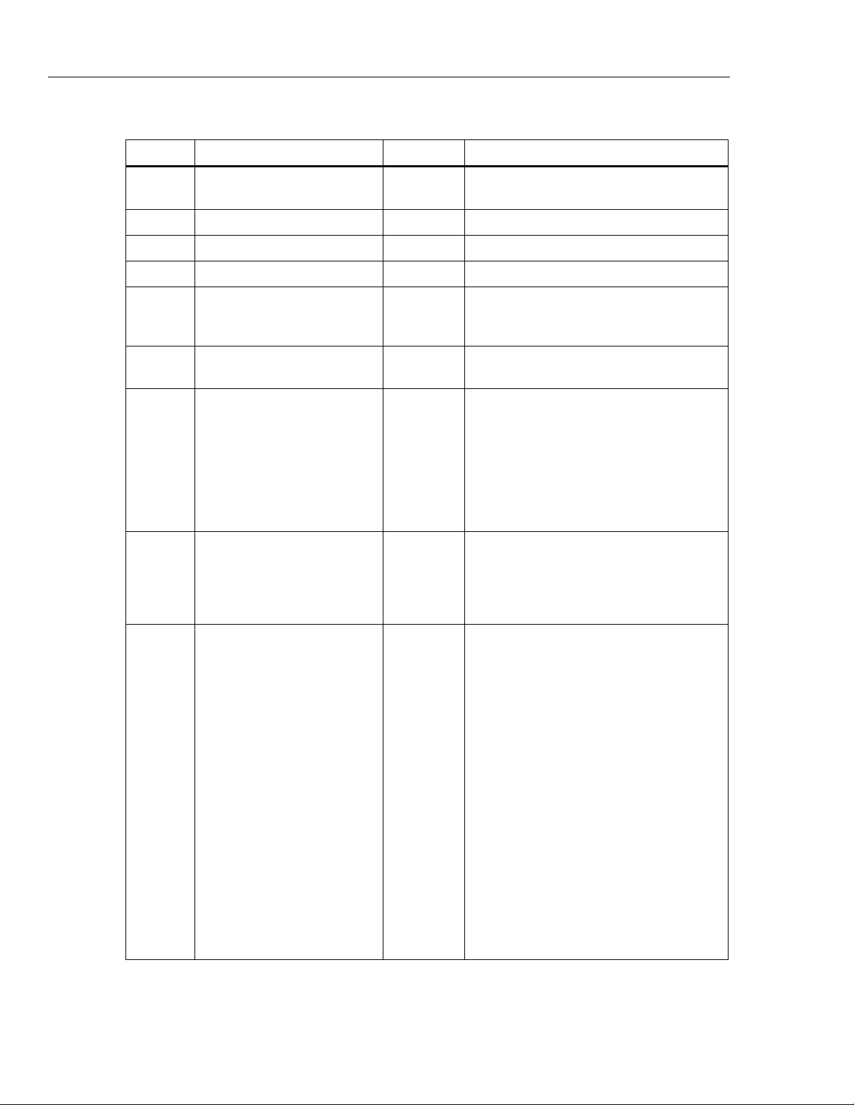
Table 1 shows the symbols used on the Product and in this manual.
Warning
To prevent possible electrical shock, fire, or personal injury:
• Use the Product only as
supplied by the Product can be compromised.
specified, or the protection
• Use onl
amperage rated probes, test leads, and adapters for the
measurement.
• Do not touch voltages > 30 V ac rms, 42 V ac peak, or
60 V dc.
• Carefull
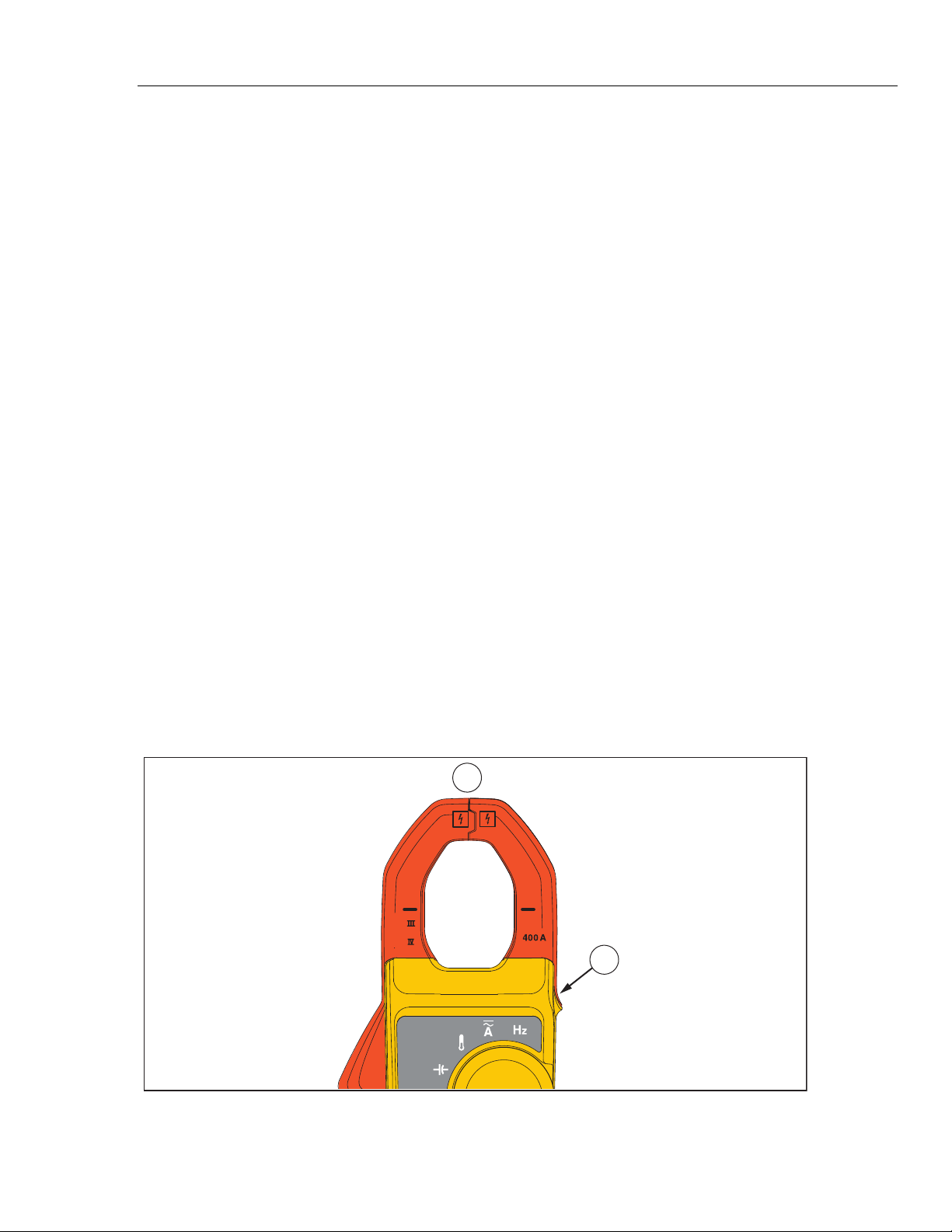
• Hold the Product behind the tactile barrier. See Figure 1,
item .
• Do not exceed the Measurement Category
the lowest rated individual component of a Product, probe,
or accessory
• Do not measure current while the t
jacks.
• Do not use the Product around explosive gas, vapor, or in
damp or wet environments.
• Limit operation to the specified measurement category
voltage, or amperage ratings.
• Do not w
• Do not apply
terminals or betw
• Compl
protective equipment (approved rubber gloves, face
protection, and flame-resistant clothes) to prevent shock
and arc blast injury where hazardous live conductors are
exposed.
• Replace the batteries w
to prevent incorrect m
• The battery
operate the Product.
• Measure a
operates correctl
• Remove all probes, test leads, and accessories that are not
necessary for the measurement.
• Onl
same measurement category
Product.
Keep fingers behind the finger guards on the probes.
•
y correct measurement category
ad all instructions.
y re
.
ork
alone.
more than the rated voltage, between
ach terminal and earth ground.
een e
y with local and national safety codes.
hen the low battery indicator shows
easurements.
door must be closed and locked before y
y use pr
known volt
obes, test leads, and accessories that have the
age first to make sure that the Product
y.
voltage rating as the
and
(CAT), voltage, and
(CAT) rating
est leads are in the input
Use personal
of
,
the
ou
2
Find Quality Products Online at: [email protected]
www.GlobalTestSupply.com
Page 8
• Connect the common test lead before the live test lead and
remove the live test lead before the common test lead.
• Remove all probes, test leads, and accessories before the
battery
r is opened.
doo
• Do not use and disable the Product if it is damaged.
• Do not use the Product if it operates incorrectl
• Do not use test leads if they are da
maged. Examine the test
y.
leads for damaged insulation, exposed metal. Check test
lead continuity
•
Before each use, examine the Product. Look for cracks or
.
missing pieces of the clamp housing. Also look for loose or
w
eakened components. Carefully
around the ja
ws. See Figure 1, item
• Examine the case before
you use
examine the insulation
.
the Product. Look for
cracks or missing plastic. Carefully look at the insulation
around the terminals.
• Read all safety
information before you use the
• Remove batteries to prevent battery
leakage
Product.
and damage to
the Product if it is not used for an extended period.
• Remove the batteries if the Product is not used for an
extended period of time, or if stored in temperatures above
50 °C. If the
batteries are not removed, battery
leakage can
damage the Product.
Clamp Meter
Safety Information
Caution
To prevent possible damage to the Product or to equipment
under test, use a thermocouple rated for the temperatures to be
measured. The Product is rated for -10.0 °C to +400.0 °C and
14 °F to 752 °F. The included type-K thermocouple is rated to
260 °C.
2
CAT
600 V
CAT
300 V
1
Figure 1. Clamp Jaw (325 is Shown)
Find Quality Products Online at: [email protected]
www.GlobalTestSupply.com
hfk002.eps
3
Page 9
323/324/325
Calibration Manual
Symbol Meaning Symbol Meaning
Table 1. Symbols
Hazardous voltage. Risk of
electric shock.
AC (Alternating Current)
Risk of Danger. Important information. See
Manual.
DC (Direct Current)
AC and DC Current Earth Terminal
CAT II
Double insulated
Application to or removal from
hazardous, live conductors is
permitted.
Conforms to relevant
Australian EMC standards.
This product has been tested
to the requirements of
CAN/CSA-C22.2 No. 61010-1,
second edition, including
Amendment 1, or a later
version of the same standard
incorporating the same level of
testing requirements.
Measurement category II is
applicable to test and
measuring circuits connected
directly to utilization points of
low voltage mains installation.
Battery
Conforms to European Union directives.
CAT III
Inspected and licensed by TÜV Product
Services.
Conforms to European Union directives.
Measurement Category III is applicable to
test and measuring circuits connected to the
distribution part of the building’s low-voltage
MAINS installation.
CAT IV
Measurement Category IV is
applicable to test and
measuring circuits connected
at the source of the building’s
low-voltage MAINS
installation.
This product complies with the WEEE
Directive (2002/96/EC) marking
requirements. The affixed label indicates
that you must not discard this
electrical/electronic product in domestic
household waste. Product Category: With
reference to the equipment types in the
WEEE Directive Annex I, this product is
classed as category 9 "Monitoring and
Control Instrumentation” product. Do not
dispose of this product as unsorted
municipal waste. Go to Fluke’s website for
recycling information.
Note
This product complies with the
Regulation for the Administration of the
Recovery and Disposal of Waste
Electrical and Electronic Products
(China).
4
Find Quality Products Online at: [email protected]
www.GlobalTestSupply.com
Page 10

Note
The Measurement Category (CAT) and voltage rating of combinations of
test probes, test probe accessories, current clamp accessories, and the
Product is the LOWEST rating of individual components.
Specifications
Electrical Specifications
AC Current (Jaw)
Range
323 ..................................................... 400.0 A
324, 325 ............................................. (40.00, 400.0) A
Resolution
323 ..................................................... 0.1 A
324, 325 ............................................. (0.01, 0.1) A
Accuracy
323, 325 ............................................ 2.0 % ±5 digits (45 - 65 Hz)
2.5
% ±5 digits (65 - 400 Hz)
324 .................................................... 1.5 % ±5 digits (45 Hz to 400 Hz)
Note: Add 2 % for position sensitivity
Clamp Meter
Specifications
DC Current with Jaw (325)
Range ..................................................... (40.00, 400.0) A
Resolution ............................................... (0.01, 0.1) A
Accuracy ................................................. 2.0 % ± 5 digits
AC Voltage
Range ..................................................... 600.0 V
Resolution ............................................... 0.1 V
Accuracy (45 – 400 Hz) .......................... 1.5 % ± 5 digits
DC Voltage
Range .................................................... 600.0 V
Resolution ............................................... 0.1 V
Accuracy ................................................. 1 % ± 5 digits
Resistance
Range
323, 324 ............................................. (400.0, 4000) Ω
325 ..................................................... (400.0, 4000, 40000) Ω
Resolution ............................................... (0.1, 1, 10) Ω
Accuracy ................................................. 1 % ±5 digits
Continuity Beeper
323 .................................................... ≤70 Ω
324/325 ............................................. ≤30 Ω
Capacitance (324, 325)
Range ..................................................... (100.0, 1000) μF
Resolution ............................................... (0.1, 1) μF
Accuracy ................................................. 1 % ±4 digits
Frequency (325)
Range ..................................................... 5.0 to 500.0 Hz
Resolution ............................................... 0.1 Hz
Accuracy ................................................. 0.5 % ±4 digits
Trigger Level ........................................... 5 to 10 Hz, ≥10 A
10 to 100 Hz, ≥5 A
100 to 500 Hz, ≥10 A
5
Find Quality Products Online at: [email protected]
www.GlobalTestSupply.com
Page 11

323/324/325
Calibration Manual
Contact Temperature (324, 325)
Range ..................................................... -10.0 °C to 400.0 °C
Resolution ............................................... 0.1 °C
Accuracy ................................................. 1 % ±8 digits
Note: Temperature uncertainty (accuracy) does not include error of the thermocouple probe.
Mechanical Specifications
Size (L x W x H) ..................................... (207 x 75 x 34) mm
Weight
323 ..................................................... 265 g
324 ..................................................... 208 g
325 ..................................................... 283 g
Environmental Specifications
Operating Temperature ........................... -10 °C to +50 °C
Storage Temp ......................................... -30 °C to +60 °C
Operating Humidity ................................. Non Condensing (≤10 °C)
Operating Altitude
Storage Altitude ...................................... 12,000 meters
EMI, EMC ................................................ Meets all applicable requirements in EN/IEC 61326-1
Temperature Coefficients........................ Add 0.1 x specified accuracy for each degree C above 28 °C or below 18 °C
Over Voltage Category ........................... CAT IV 300 V, CAT III 600 V
Safety Compliance .................................. EN/IEC 61010-1, Pollution Degree 2
Agency Approvals ................................... Complies with CAN/CSA-C22.2 No. 61010-1
IP Rating ................................................. IP 30 Per IEC 60529; Non-operating
Batteries .................................................. 2 AAA, NEDA 24A, IEC LR03
≤90 % RH (at 10 °C to 30 °C)
≤75 % RH (at 30 °C to 40 °C)
≤45 % RH (at 40 °C to 50 °C)
(Without
................................... 2000 meters
EN/IEC 61010-2-032
EN/IEC 61010-031
Conden
sation)
6
Find Quality Products Online at: [email protected]
www.GlobalTestSupply.com
Page 12

Maintenance
Clean the Product
To prevent possible damage to the Product or to equipment
under test, do not use abrasive cleaners. They will damage the
case.
Regularly wipe the case with a damp cloth and weak detergent.
To clean the Product Jaw:
Clamp Meter
Maintenance
Caution
1. Examine the jaw-mating surface to make sure it is clea
al (including rust), jaw closure will not be corre
materi
measurement errors.
2. Open the jaws and clean the cla
Battery Replacement
To prevent possible explosion, fire, or personal injury, replace
the batteries when the low battery indicator (B) shows to
prevent incorrect measurements.
To prevent possible damage to the Product or to equipment
under test:
• Remove batteries to prevent battery leakage
the Product if it is not used for an extended period.
• Be sure that the battery
leakage.
To change the batteries, s
1. Make sure the Product is o
2. Turn over t
3. Use a flat-h
the battery
he Product to access the battery compartm
compartm
n. If there is unwanted
ct and there will be
mp metal ends with a non-flammable oil and cloth.
Warning
Caution
and damage to
polarity is correct to prevent battery
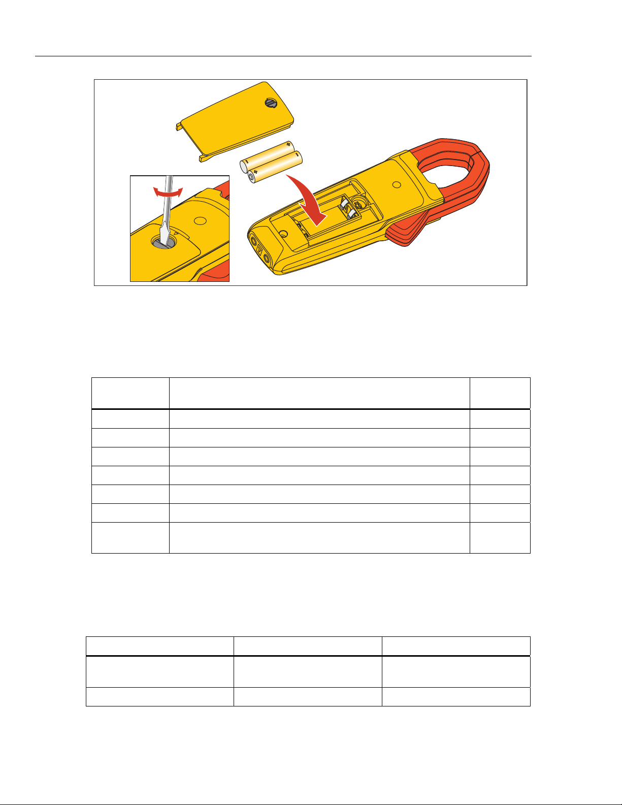
ee Figure 2:
ff.
ent door screw.
ead screwdriver to loosen the battery compartm
ent door.
ent door screw and lift off
4. Replace the t
the batteries i
5. Reattach the battery
6. Tighten the b
Find Quality Products Online at: [email protected]
wo AAA batteries. Make sure to use the correct polarity when you
nto the battery compartm
compartm
attery compartm
ent door.
ent door screw.
ent door.
www.GlobalTestSupply.com
put
7
Page 13
323/324/325
Calibration Manual
AAA
Figure 2. Battery Replacement
User-Replaceable Parts
User-replaceable parts are shown in Table 2.
Table 2. User-Replaceable Parts
Fluke Part
Number
3986568 FLUKE-CAP-2001,TL7X PROBE CAP,BLACK 1
3986579 FLUKE-CAP-2001-01,TL7X PROBE CAP,FLUKE RED 1
2838018 BATTERY 1.5V LR03 ALKALINE AAA 2
4146344 BATTERY DOOR 1
4166286 SOFT CASE BLACK/YELLOW VINYL 1
4045153 323/324/325 USERS MANUAL 1
1997234
THERMOCOUPLE ASSEMBLY K-TYPE BEADED MOLDED DUAL
BANANA PLUG COILED BULK
Description Qty
Required Equipment
The equipment in Table 3 is necessary for the performance tests and calibration
adjustment.
hfj007.eps
1
Table 3. Required Equipment
Equipment Required Characteristics Recommended Model
Calibrator 4.5-digit resolution
Wired coil 50 turns 5500A/COIL
Fluke 5520A Calibrator or
Equivalent
8
Find Quality Products Online at: [email protected]
www.GlobalTestSupply.com
Page 14
Performance Tests
To prevent possible electrical shock, fire, or personal injury,
do not go through the performance test procedures unless the
Product is fully assembled.
The performance tests verify the full operation of the Product and measure the accuracy
of each function against Product specifications. If the Product fails a part of the test,
calibration adjustment and/or repair is necessary. See “Calibration Adjustment”.
Before you do the performance tests:
Clamp Meter
Performance Tests
Warning
1. Make sure that you have the necessary equipm
2. Make sure the Product batt
Replacement
3. War
m up the Calibrator as necessary. Refer to its spec
4. Let the te
Test the Display
To verif
y that all segments of the display function:
1. With the Product off, push and hold any of the buttons.
2. Turn the rotar
segments are
ments of the display are missing, repair is necessary. See “Contact Fluke”.
If seg
ent. See Table 3.
eries are good and replace them if necessary. See “Battery
”.
ifications.
mperature of the UUT (unit under test) become stable to room temperat
y switch on while you hold down the button. All of the display
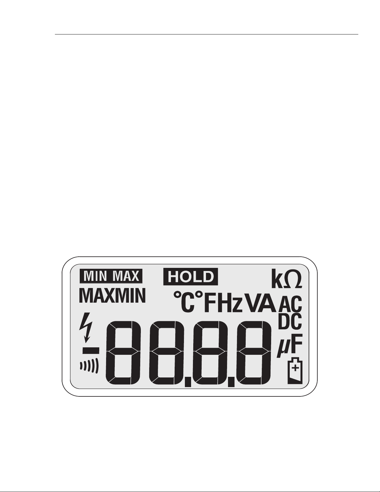
shown. See Figure 3.
ure.
Figure 3. Display Segments (324 and 325 Display is Shown)
Find Quality Products Online at: [email protected]
www.GlobalTestSupply.com
hfk001.eps
9
Page 15

323/324/325
Calibration Manual
Firmware Version and Model Number
To see the Product firmware version and model number:
323:
1. Turn on the Product with the HOLD button held down.
2. After the display segments are shown, release the HOL
3. The Product shows:
• “POFF” for the auto-power off function
• “r003” or the
• “F323” (Fluke
25:
324/3
1. Turn on the Product.
2. The display
“F32X” (Flu
1. Turn on the Product with the F/C button held down.
2. After the display segments are shown, release the F/C
3. The display shows:
“r0.52” or the current firmware version
Backlight (324 and 325)
To verif
y that the backlight functions:
1. With the Product on, push . The backlight will co
2. Push again to turn the
D button.
current firmware version
323)
shows:
ke 324 or Fluke 325)
button.
me on.
backlight off.
3. If the backlight does not function correctly, repair is necessary.
Button Test
To verify
Each button push causes the Product to beep and the display to change. For the 324 and
325, note that the Product beeps twice if the Product is in the wrong mode for the pushed
button. If the buttons do nothing, repair is necessary. See “Contact Fluke”.
See “Contact Fluke”.
that the buttons function, turn on the Product and push each button separately.
10
Find Quality Products Online at: [email protected]
www.GlobalTestSupply.com
Page 16
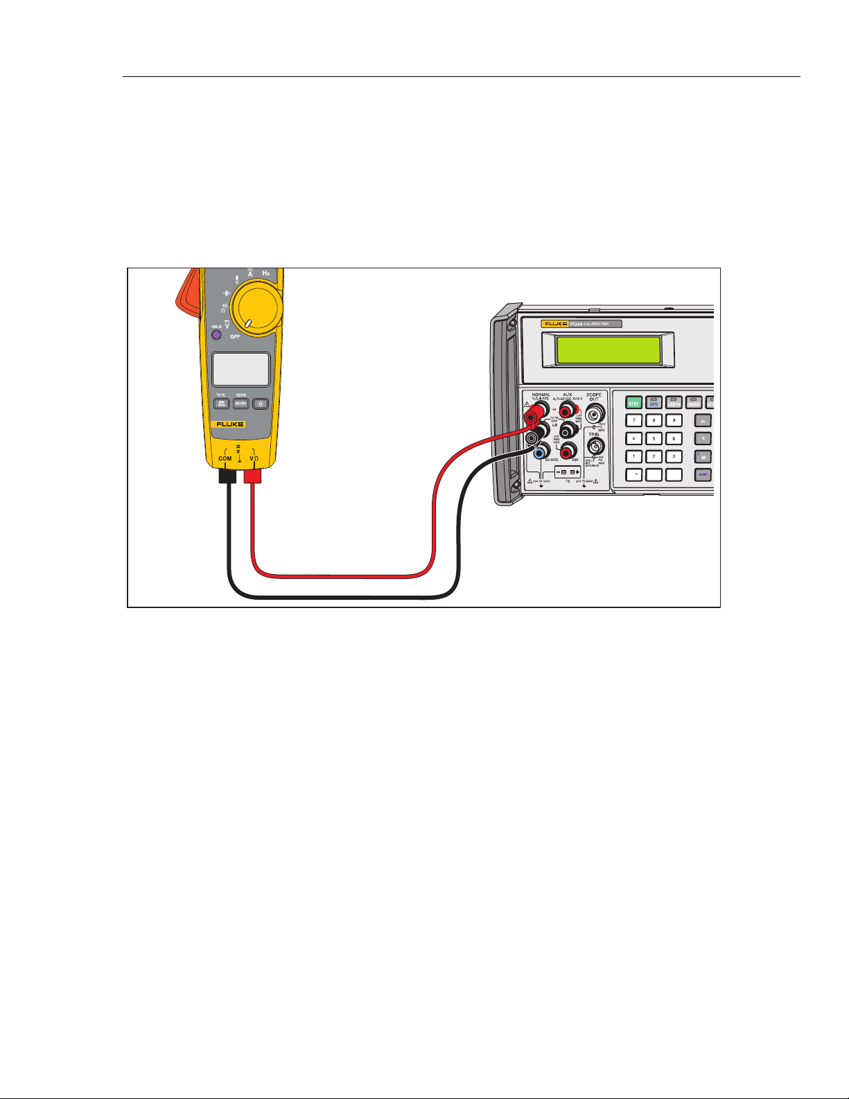
Temperature, Volts, Ohms, Frequency, and Capacitance
300V
CAT
600VCAT
325
TRUE RMS CLAMP METER
To do the temperature, volts, ohms, and capacitance performance tests:
Clamp Meter
Performance Tests
1. Connect the Calibrator NORMAL output and ground to the Product. See Figur
the connections.
2. Appl
y the values shown in
If the Product
shows indications outside of the limits shown in Table 4, calibration
Table 4.
adjustment is necessary. See “Calibration Adjustment”.
5522A
+
/
0
e 4 for
•
Figure 4. Temperature, Volts, Ohms, Frequency, and Capacitance Performance Test Connections
hfk07.eps
Find Quality Products Online at: [email protected]
www.GlobalTestSupply.com
11
Page 17
323/324/325
Calibration Manual
Current
To do the current tests:
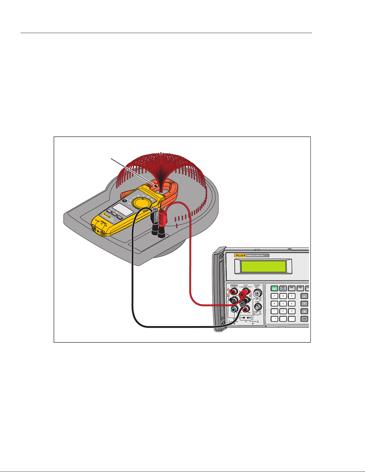
1. Connect the Calibrator current output and ground to the 50-Turn Coil. See Figur
2. Turn the Product to the nec
3. Apply
4. Co
the input level for each step shown in Table 4.
mpare the indication on the Product display with the UUT reading lim
essary current mode.
its in
Table 4.
5. If the Product
ment is necessary. See “Calibration Adjustment
adjust
Conductor
shows indications outside of the limits shown in Tabl
”.
50-Turn Coil
e 4, calibration
5522A
e 5.
+
/
•
0
Figure 5. AC Current Test Connections
hfk025.eps
12
Find Quality Products Online at: [email protected]
www.GlobalTestSupply.com
Page 18
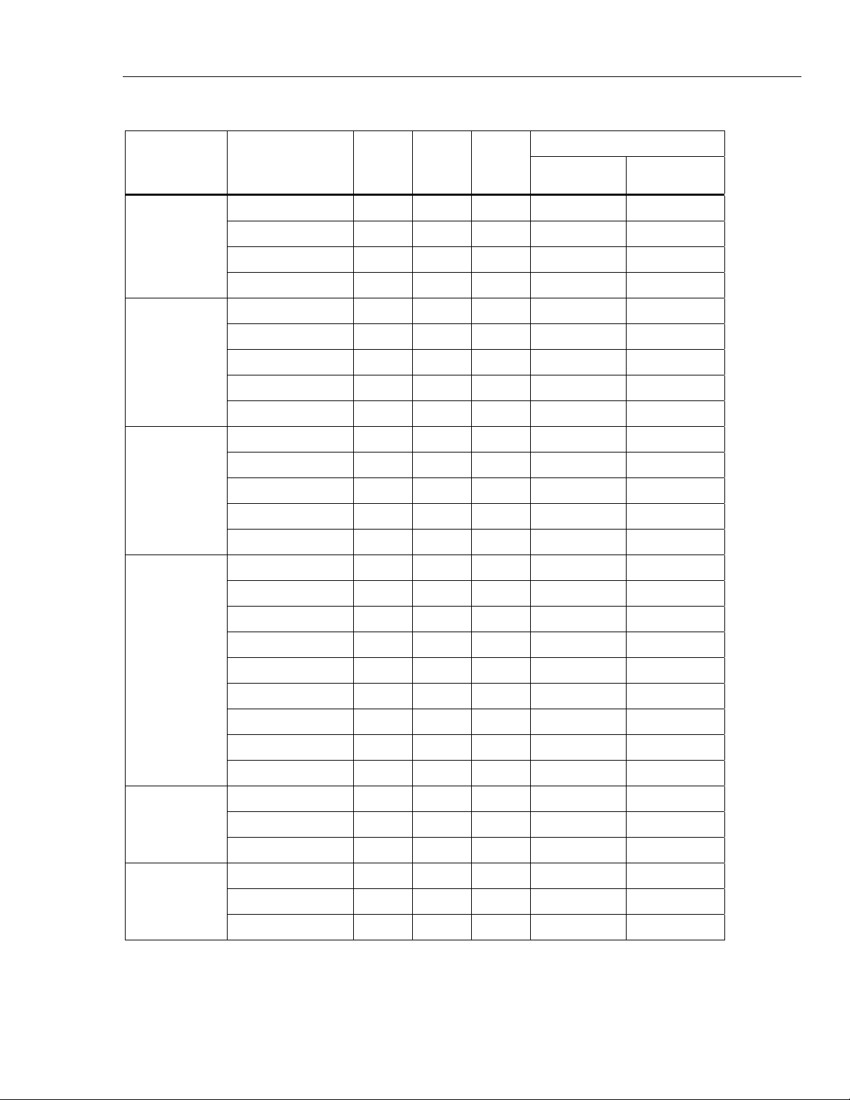
Table 4. Performance Tests
Clamp Meter
Performance Tests
Test
(Switch
Position)
Temperature
AC Volts
DC Volts
Calibrator
Output
-5 °C N/A X X -5.8 °C -4.2 °C
0 °C N/A X X -0.8 °C 0.8 °C
100 °C N/A X X 98.2 °C 101.8 °C
400 °C N/A X X 395.2 °C 404.8 °C
10 V @ 50 Hz X X X 9.3 V 10.7 V
500 V @ 50 Hz N/A X X 492.0V 508.0 V
500 V @ 500 Hz N/A X X 492.0V 508.0 V
600 V @ 50 Hz X N/A N/A 590.5 V 609.5 V
600 V @ 400 Hz X N/A N/A 590.5 V 609.5 V
-600 V X N/A N/A -606.5 -593.5 V
-500 V N/A X X -505.5 V -494.5 V
10 V X X X 9.4 V 10.6 V
500 V N/A X X 494.5 V 505.5 V
600 V X N/A N/A 593.5 V 606.5 V
323 324 325
Meter Reading Limit
Low High
Ohms
Capacitance
Frequency
0 Ω X N/A N/A 0.0 Ω 0.5 Ω
10 Ω X X X 9.4 Ω 10.6 Ω
300 Ω N/A X X 296.5 Ω 303.5 Ω
350 Ω X N/A N/A 346.0 Ω 354.0 Ω
1000 Ω N/A X X 985 Ω 1015 Ω
3000 Ω N/A X X 2965 Ω 3035 Ω
3500 Ω X N/A N/A 3460 Ω 3540 Ω
10K Ω N/A X X 9.85 KΩ 10.15 KΩ
30K Ω N/A X X 34.65 KΩ 30.35 Ω
10 μF N/A X X 9.5 μF 10.5 μF
500 μF N/A X X 491 μF 509 μF
900 μF N/A X X 887 μF 913 μF
0.2 A, 5 Hz N/A N/A X 4.7 Hz 5.3 Hz
0.2 A, 50 Hz N/A N/A X 49.6 Hz 50.4 Hz
0.2 A, 500 Hz N/A N/A X 497.5 Hz 501.5 Hz
13
Find Quality Products Online at: [email protected]
www.GlobalTestSupply.com
Page 19
323/324/325
Calibration Manual
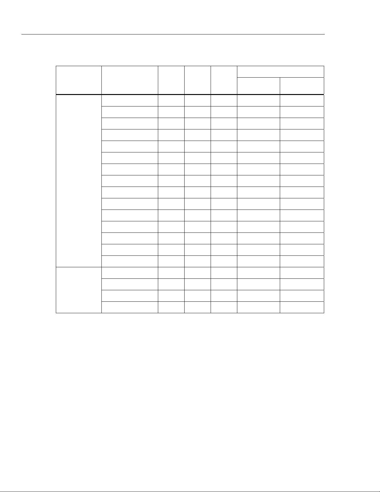
Table 4. Performance Tests (cont.)
Test
(Switch
Position)
AC Amps
(with 50Turn Coil)
Calibrator
Output
0.12 A @ 50 Hz X N/A N/A 5.4 A 6.6 A
0.48 A @ 150 Hz X N/A N/A 22.9 A 25.1A
4.2 A @ 50Hz X N/A N/A 205.3 A 214.7 A
7.8 A @ 50 Hz X N/A N/A 381.7 A 398.3 A
7.8 A @ 150 Hz X N/A N/A 379.7 A 400.3 A
7.8 A @ 400 Hz X N/A N/A 379.7 A 400.3 A
0.004 A @ 50 Hz N/A X N/A 0.15 A 0.25 A
0.2 A @ 50 Hz N/A X N/A 9.80 A 10.20 A
0.6 A @ 50 Hz N/A X N/A 29.50 A 30.50 A
2 A @ 50 Hz N/A X N/A 97.5 A 102.5 A
6 A @ 50 Hz N/A X N/A 293.5 A 306.5 A
0.2 A @ 50 Hz N/A N/A X 9.75 A 10.25 A
0.6 A @ 50 Hz N/A N/A X 29.35 A 30.65 A
2 A @ 50 Hz N/A N/A X 98.0 A 102.0 A
323 324 325
Meter Reading Limit
Low High
DC Amps
(with 50Turn Coil)
6 A @ 50 Hz N/A N/A X 295.0A 305.0 A
0.2 A N/A N/A X 9.75 A 10.25 A
0.6 A N/A N/A X 29.35 A 30.65 A
2 A N/A N/A X 97.5 A 102.5 A
6 A N/A N/A X 293.5 A 306.5 A
14
Find Quality Products Online at: [email protected]
www.GlobalTestSupply.com
Page 20

Calibration Adjustment
The Product features closed-case calibration adjustment and uses known reference
sources. The Product measures the applied reference source, calculates correction factors,
and stores the correction factors in nonvolatile memory.
Should the Product fail any of the performance tests, do the calibration adjustment
procedure.
To do the calibration adjustment:
Clamp Meter
Calibration Adjustment
1. Remove the Product battery door. See “Battery
2. Apply
3. Turn the rotar
4. Re
5. Short across the CAL key
6. When “C-1.2” is shown on
7. After each step, push
For 323,
After you push the HOLD button, wait until the calibration step number
advances before you change the calibrator source. Some adjustment steps
can take several seconds to execute before the Product goes to the
subsequent step.
8. When calibration adjustment is complete, remove the 3.0 V supply. The Product
3.0 V across the battery contacts on the pca. Note the polarity that is show
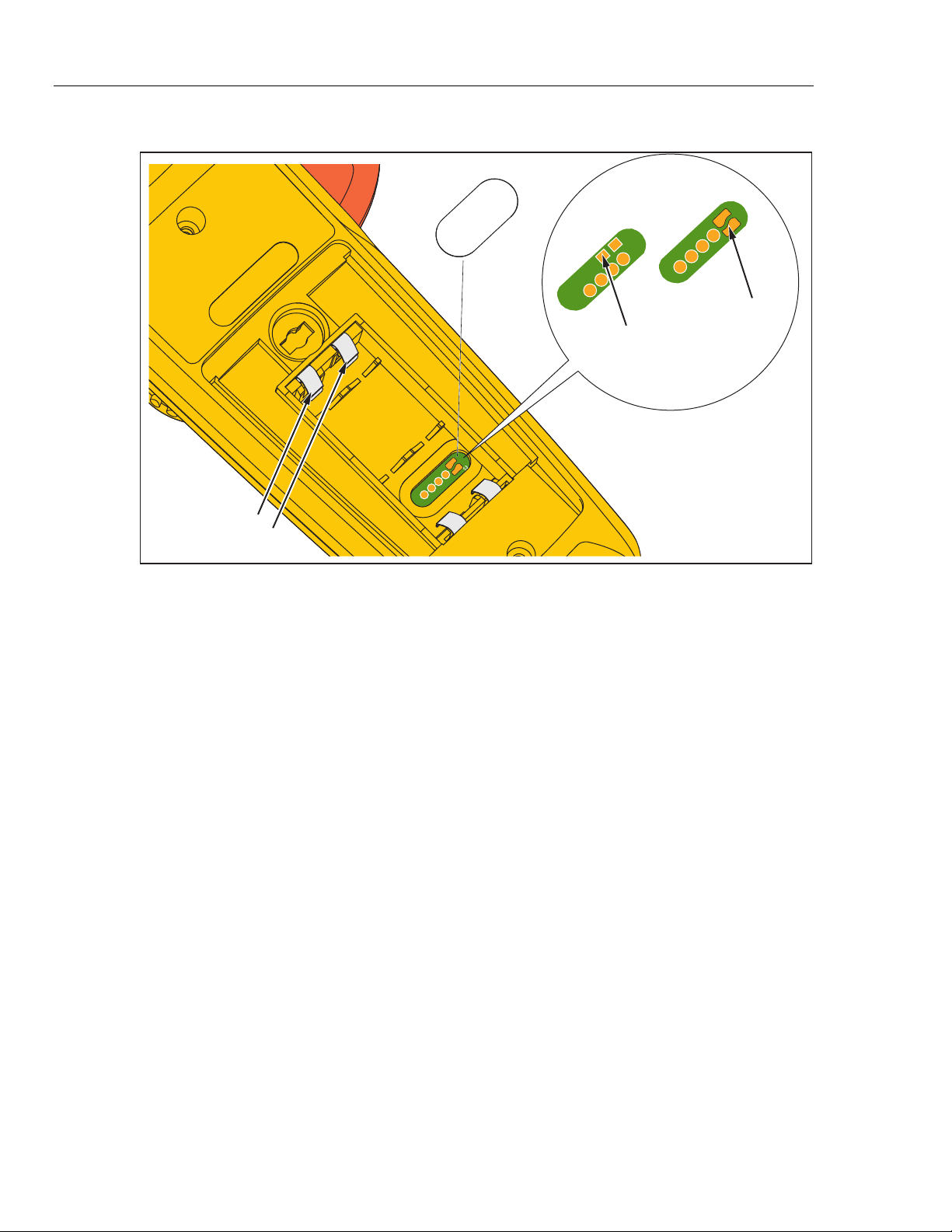
Figure 6.
y switch to the function that you will adju
move the ca
This puts the Product into
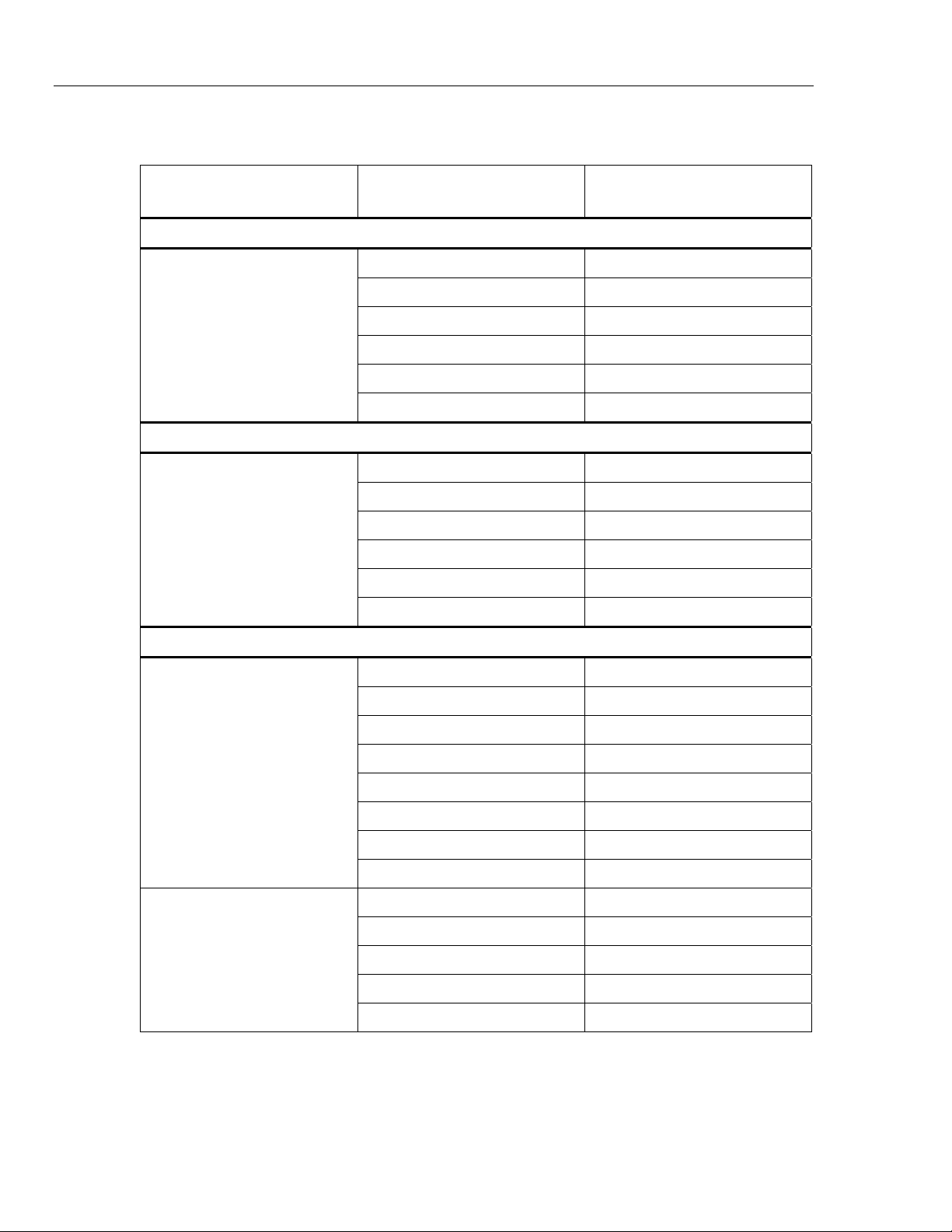
the Calibrator to the Product as shown in Table 5. After confirmation, the Product
goes to the subsequent calibration step.
next step. Set the Calibrator to Standby a
function.
if any calibration point is missing “Err” is shown on the display.
automatically
libration seal.
pad on the pca and then remove the short. See Figure 6.
calibration mode.
the Product display, apply the correct input signals from
the HOLD button to confirm the calibration step and go to th
exit calibration m
Notes
ode.
Replacement”.
st.
fter you complete adjust
ment of each
n in
e
will
9. Replace the batteries and battery door.
15
Find Quality Products Online at: [email protected]
www.GlobalTestSupply.com
Page 21
323/324/325
Calibration Manual
seal
calibration
323 CAL Keypad
324 and 325
CAL Keypad
Battery Contacts
Figure 6. Short the CAL Keypad
hfk03.eps
16
Find Quality Products Online at: [email protected]
www.GlobalTestSupply.com
Page 22
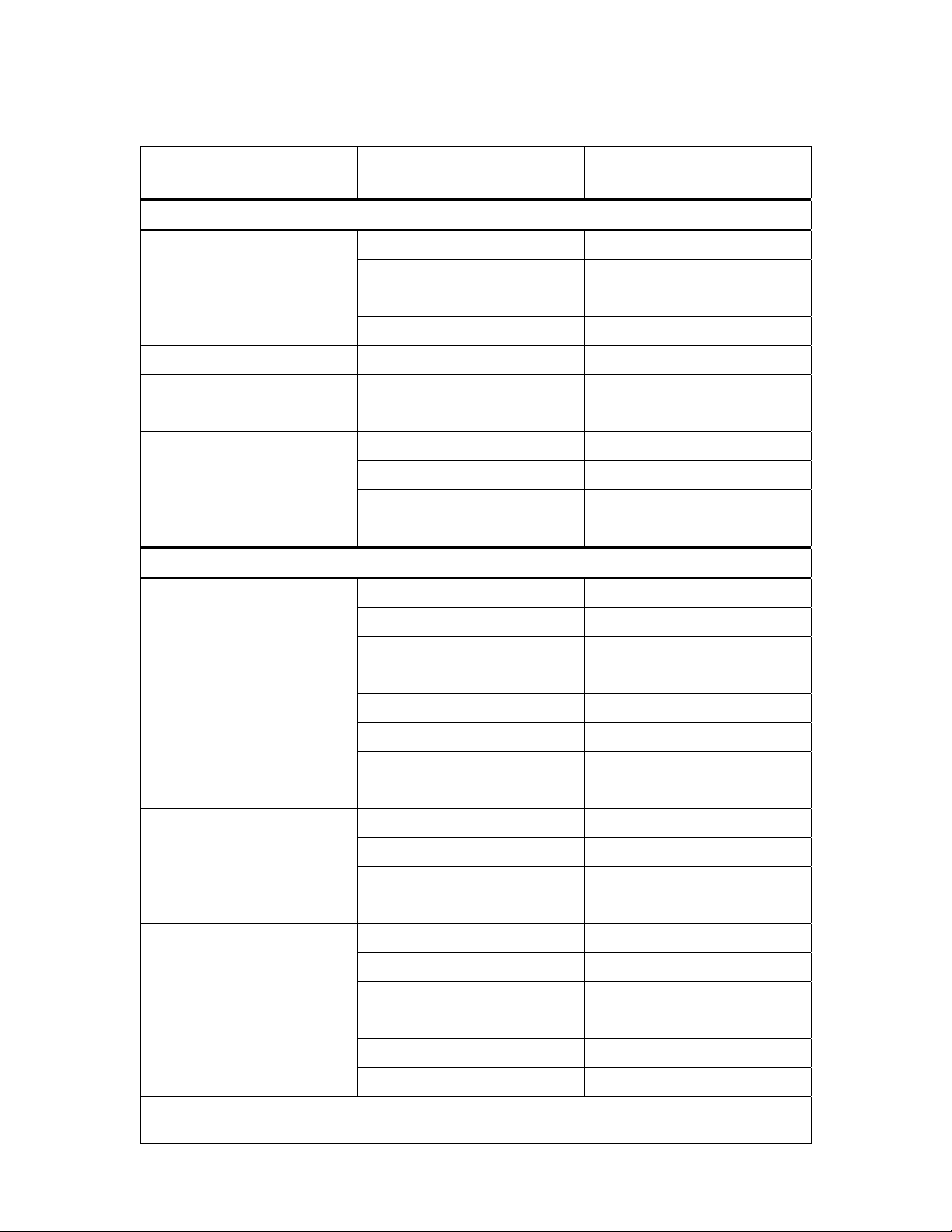
Table 5. Calibration Adjustment
Clamp Meter
Calibration Adjustment
Test
(Switch Position)
C-1.1 1.05 V, 50 Hz
AC Volts
DC Volts C-2.2 400 V
Ohms
AC Amps
(with 50-Turn Coil)
C-1.2 40 V, 50 Hz
C-1.3 10 V, 50 Hz
C-1.4 300 V, 50 Hz
C-3.1 400 Ω
C-3.2 4000 Ω
C-4.1 0.019 A, 50 Hz
C-4.2 0.42 A, 50 Hz
C-4.3 1.026 A, 50 Hz
C-4.4 6 A, 50 Hz
C-21 0 V
LCD Reading Calibrator Output
323
[1]
324 and 325
Temperature
AC Volts
DC Volts
Ohms
C-22 0.02 V
C-23 0.02 V
C-00 600 V, 50 Hz
C-01 600 V, 100 Hz
C-02 600 V, 200 Hz
C-03 600 V, 300 Hz
C-04 600 V, 400 Hz
C-05 0 V
C-06 600 V
C-07 0 V
C-08 0.5 V
C-09 0 Ω
C-10 400 Ω
C-11 440 Ω
C-12 4000 Ω
C-13 (325 only) 4400 Ω
C-14 (325 only) 40000 Ω
[1] At each function, after all calibration points is adjusted, the display shows “Save” after the last
calibration point. Push HOLD to save the calibration data.
17
Find Quality Products Online at: [email protected]
www.GlobalTestSupply.com
Page 23
323/324/325
Calibration Manual
Table 8. Calibration Adjustment (cont.)
Test
(Switch Position)
Capacitance
AC Amps
(with 50-Turn Coil)
LCD Reading Calibrator Output
324 and 325
C-15 0.1 μF
C-16 0.5 μF
C-17 1.5 μF
C-18 110 μF
C-19 500 μF
C-20 1000 μF
324
C-24 0.8 A, 50 Hz
C-25 0.8 A, 100 Hz
C-26 0.8 A, 200 Hz
C-27 0.8 A, 300 Hz
C-28 0.8 A, 400 Hz
C-29 8 A,50 Hz
AC Amps
(with 50-Turn Coil)
DC Amps
(with 50-Turn Coil)
325
C-24 0 A
C-25 0.02 A, 50 Hz
C-26 0.8 A, 50 Hz
C-27 0.8 A, 100 Hz
C-28 0.8 A, 200 Hz
C-29 0.8 A, 300 Hz
C-30 0.8 A, 400 Hz
C-31 8 A, 50 Hz
C-32 0 A
C-33 0.02 A
C-34 0.8 A
C-35 0.88 A
C-36 8 A
18
Find Quality Products Online at: [email protected]
www.GlobalTestSupply.com
Page 24

Temperature Zero Procedure (324 and 325)
1. Turn off the Product and wait 20 minutes.
Clamp Meter
Temperature Zero Procedure (324 and 325)
2. Connect a K-type therm
3. After 20 m
and short across the CAL keypad on
4. Turn the Product rotary switch to tem
5. Push twice until “C-23” shows on t
6. Apply 0 °C from
7. Push the HOLD button
8. Push the HOLD button
The calibration adjustm
inutes, with the Product still connected to the 3.0 V, turn on th
the Calibrator.
ocouple connector from the Calibrator to th
th
e pca. See Figure 6.
per
to confirm C-23
to save the calib
ent procedure is complete.
e Product.
e Product
ature.
he Product display.
.
ration data.
19
Find Quality Products Online at: [email protected]
www.GlobalTestSupply.com
 Loading...