

Page 1

Introduction
To prevent possible electrical shock, fire, or personal injury:
• Read all safety information before you use the Product.
• Do not do the performance tests or calibration adjustment
procedures unless qualified to do so.
• Carefully read all instructions.
The 28 II Ex Calibration Information contains adjustment and performance test
procedures for the Fluke Model 28 II Ex Digital Multimeter (the Product or Meter).
This document includes:
• Safety Information (page 2)
• International Electrical Symbols (page 4)
• Specifications (page 5)
• General Maintenance (page 9)
• Fuse Test (page 9)
• Performance Tests (page 12)
• Calibration Adjustment Procedure (page 16)
• Limited Lifetime Warranty (page 20)
28 II Ex
Digital Multimeter
Calibration Information
XWWarning
See the 28 II Ex Users Manual for instructions on Product operation.
How to Contact Fluke
To contact Fluke, call one of the following telephone numbers:
• Technical Support USA: 1-800-99-FLUKE (1-800-993-5853)
• Calibration/Repair USA: 1-888-99-FLUKE (1-888-993-5853)
• Canada: 1-800-36-FLUKE (1-800-363-5853)
• Europe: +31 402-675-200
• Japan: +81-3-3434-0181
• Singapore: +65-6799-5566
• Anywhere in the world: +1-425-446-5500
Or, visit Fluke's website at www.fluke.com.
To register your product, visit http://register.fluke.com.
To view, print, or download the latest manual supplement, visit
http://us.fluke.com/usen/support/manuals.
May 2012
© 2012 Fluke Corporation. All rights reserved. Specifications are subject to change without notice.
All product names are trademarks of their respective companies. 1
Page 2

28 II Ex
Calibration Information
Safety Information
A Warning identifies conditions and procedures that are dangerous to the user. A
Caution identifies conditions and procedures that can cause damage to the Product or the
equipment under test.
XWWarning
To prevent possible electrical shock, fire, or personal injury:
• Use the Product only as specified, or the protection
supplied by the Product can be compromised.
• The battery door must be closed and locked before you
operate the Product.
• Replace the batteries when the low battery indicator ()
shows to prevent incorrect measurements.
• Remove all probes, test leads, and accessories before the
battery door is opened.
• Do not use test leads if they are damaged. Examine the test
leads for damaged insulation, exposed metal, or if the wear
indicator shows. Check test lead continuity.
• Do not apply more than the rated voltage, between the
terminals or between each terminal and earth ground.
• Limit operation to the specified measurement category,
voltage, or amperage ratings.
• Do not operate the Product with covers removed or the
case open. Hazardous voltage exposure is possible.
• Do not touch voltages > 30 V ac rms, 42 V ac peak, or 60 V
dc.
• Use the correct terminals, function, and range for
measurements.
• Do not work alone.
• Measure a known voltage first to make sure that the
Product operates correctly.
• Use only cables with correct voltage ratings.
• Use only current probes, test leads, and adapters supplied
with the Product.
• Do not exceed the Measurement Category (CAT) rating of
the lowest rated individual component of a Product, probe,
or accessory.
• Connect the common test lead before the live test lead and
remove the live test lead before the common test lead.
2
Page 3

Digital Multimeter
Safety Information
• Examine the case before you use the Product. Look for
cracks or missing plastic. Carefully look at the insulation
around the terminals.
• Do not use and disable the Product if it is damaged.
• Do not use the Product if it operates incorrectly.
• Do not use the Product in damp or wet environments.
• Keep fingers behind the finger guards on the probes.
• Measure for hazardous voltage without the Low-Pass Filter.
WCaution
To prevent possible damage to the Meter or to the equipment
under test, follow these guidelines:
• Disconnect circuit power and discharge all high-voltage
capacitors before you do resistance, continuity, diodes, or
capacitance tests.
• Use the correct terminals, function, and range for all
measurements.
• Before you measure current, check the fuses of the Meter.
(See “Fuse Test”.)
3
Page 4
28 II Ex
Calibration Information
Electrical Symbols
Table 1 is a list of electrical symbols that appear in this document and on the Meter.
Table 1. Symbols
X
W
R
CAT III
(
®
~
AC (Alternating Current)
DC (Direct Current)
Hazardous voltage
Risk of Danger. Important
information. See Manual.
Battery. Low battery when
displayed.
Continuity test or continuity
beeper tone.
IEC Overvoltage Category III
CAT III equipment is designed to
protect against transients in
equipment in fixed-equipment
installations, such as distribution
panels, feeders and short
branch circuits, and lighting
systems in large buildings.
Conforms to ATEX directive.
Inspected and licensed by TÜV
Product Services.
Do not dispose of this product as unsorted municipal waste. Go to Fluke’s website for
recycling information.
J
I
P
T
CAT IV
Æ
Earth ground
Fuse
Conforms to European Union directives.
Diode
Double insulated
Capacitance
IEC Overvoltage Category IV
CAT IV equipment is designed to protect
against transients from the primary supply
level, such as an electricity meter or an
overhead or underground utility service.
Conforms to relevant Australian standards.
Conforms to CAN/CSA-C22.2 No. 61010-1
nd
2
, + Amendment 1.
4
Page 5

Digital Multimeter
General Specifications
General Specifications
Maximum voltage between any
terminal and earth ground ........................................... 1000 V rms
W Fuse for mA inputs .................................................. 440 mA, 1000 V FAST Fuse
W Fuse for A inputs ..................................................... 11 A, 1000 V FAST Fuse
Display ........................................................................... 6000 counts, updates 4/sec (19,999 counts in high-resolution
Altitude
Operating .................................................................... 2,000 meters
Storage ....................................................................... 10,000 meters
Temperature
Operating .................................................................... -15 °C to 50 °C
Storage ....................................................................... -40 °C to +85 °C (without battery)
Temperature coefficient ............................................... 0.05 X (specified accuracy) / °C (<18 °C or >28 °C)
Electromagnetic Compatibility (EN 61326-1:2005) .... In an RF field of 3 V/M, accuracy = specified accuracy +20
Relative Humidity .......................................................... 0 % to 80 % (0 °C to 35 °C)
0 % to 70 % (35 °C to 50 °C)
Battery Type .................................................................. 3 AAA Alkaline batteries, NEDA 24A IEC LR03
Approved Batteries ....................................................... Duracell Procell MN2400 LR03
Battery Life .................................................................... 400 hrs typical without backlight (Alkaline)
Vibration ........................................................................ Per MIL-PRF-28800 for a Class 2 instrument
Shock ............................................................................. 1 Meter drop per IEC 61010 (3 Meter drop with holster)
Size (H x W x L) ............................................................. 4.57 cm x 10.0 cm x 21.33 cm (1.80 in x 3.95 in x 8.40 in)
Size with Holster ........................................................... 6.35 cm x 10.0 cm x 19.81 cm (2.50 in x 3.95 in x 7.80 in)
Weight ............................................................................ 567.8 g (1.25 lb)
Weight with Holster and Flex-Stand............................ 769.8 g (1.70 lb)
Safety Compliance ........................................................ Complies with ANSI/ISA S82.01-2004, CAN/CSA C22.2 61010-1-
Certifications ................................................................. CSA, TÜV, P,
IP Rating ........................................................................ 67 (Non-operating. Protected against dust and the effect of
mode).
-40 °C to +60 °C (with battery)
counts, except 600 μA dc range total accuracy = specified
accuracy +60 counts. Temperature not specified
Duracell Plus MN2400 LR03
Varta Max Tech No. 4703
Varta Industrial Alcaline No. 4003 (min. operating temperature is 10 °C)
Eveready Energizer No. E92
Rayovac Alkaline AAA (U.S. Type)
Panasonic LR03XWA
04 to 600 V Measurement Category IV. Licensed by TÜV to
EN61010-1, Pollution degree 2
, ATEX, IECEx
immersion up to 1 m for 30 min.)
5
Page 6
28 II Ex
Calibration Information
Detailed Specifications
For all detailed specifications:
Accuracy is specified for 2 years after calibration, at operating temperatures of 18 °C to 28 °C, with relative humidity at
0 % to 80 %. Accuracy specifications take the form of ±([% of Reading] + [Number of least-significant digits]). In the 4
½-digit mode, multiply the number of least-significant digits (counts) by 10.
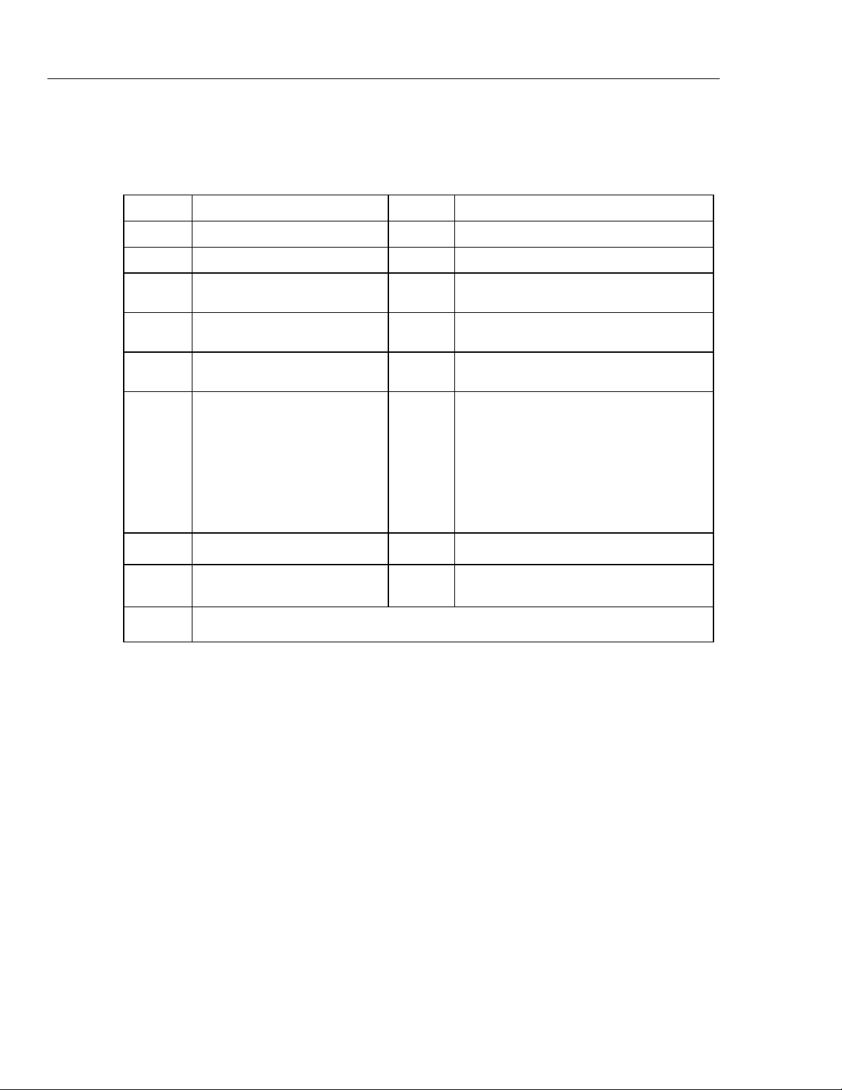
AC Voltage
AC conversions are ac-coupled and valid from 3 % to 100 % of range.
Range Resolution
600.0 mV 0.1 mV
6.000 V 0.001 V
60.00 V 0.01 V
600.0 V 0.1 V Unspecified
1000 V 1 V Unspecified Unspecified
Low-Pass Filter
[1] Below 10 % of range, add 12 counts.
[2] Frequency range: 1 kHz to 2.5 kHz
[3] Specification increases from -1 % to -6 % at 440 Hz when filter is used.
Accuracy
45 – 65 Hz 30 – 200 Hz 200 – 440 Hz 440 Hz – 1 kHz 1 – 5 kHz 5 – 20 kHz
±(0.7 % + 4)
±(1.0 % + 4)
±(2 % + 4)
±(2 % + 4)
[2]
±(2 % + 20)
Unspecified
±(0.7 % + 2)
+1.0 % + 4
±(1.0 % + 4)
[1]
-6.0 % - 4
Unspecified Unspecified Unspecified
[3]
[1]
DC Voltage, Conductance, and Resistance
Function Range Resolution Accuracy
mV dc 600.0 mV 0.1 mV
±(0.1 % + 1)
6.000 V 0.001 V
V dc
60.00 V 0.01 V
600.0 V 0.1 V
±(0.05 % + 1)
1000 V 1 V
600.0 Ω 0.1 Ω
6.000 kΩ 0.001 kΩ
Ω
60.00 kΩ 0.01 kΩ
600.0 kΩ 0.1 kΩ
6.000 MΩ 0.001 MΩ
50.00 MΩ 0.01 MΩ
nS
[1] Add 0.5 % of reading when measuring above 30 MΩ in the 50 MΩ range, and 20 counts below 33 nS in the 60 nS range.
[2] When using the rel function to compensate for offsets.
[3] >40 °C temperature coefficient is 0.1 x (specified accuracy)/°C.
60.00 nS 0.01 nS
±(0.2 % + 2)
±(0.2 % + 1)
±(0.6 % + 1)
±(1.0 % + 3)
±(1.0 % + 10)
[2]
[1,3]
[1,2,3]
Temperature
Range Resolution
-200 °C to +1090 °C
-328 °F to +1994 °F
[1] Does not include error of the thermocouple probe.
[2] Accuracy specification assumes ambient temperature stable to ± 1 °C. For ambient temperature changes of ± 5 °C, rated accuracy
applies after 2 hours.
0.1 °C
0.1 °F
Accuracy
±(1.0 % + 10)
±(1.0 % + 18)
[1,2]
6
Page 7

Digital Multimeter
Detailed Specifications
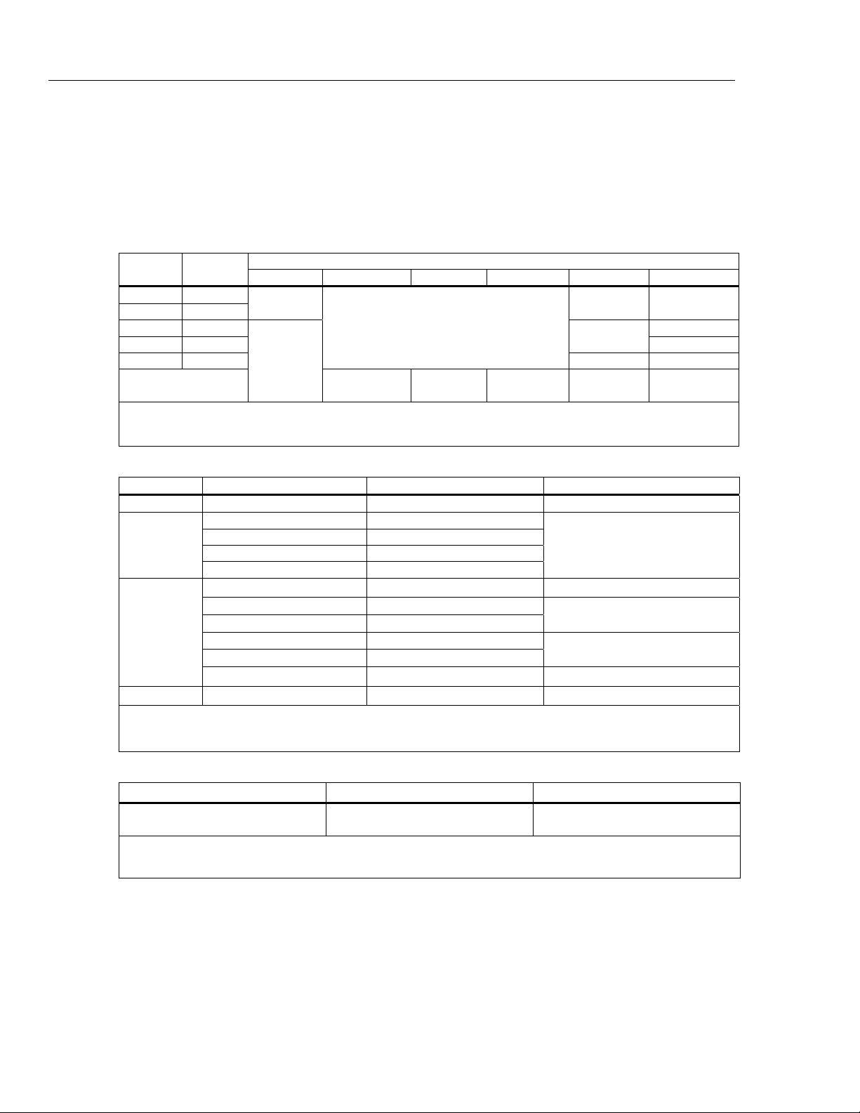
AC Current
Function Range Resolution Burden Voltage
μA ac
mA ac
A ac
[1] AC conversions are ac coupled, true rms responding, and valid from 3 % to 100 % of range, except 400 mA range. (5 % to 100 %
of range) and 10 A range (15 % to 100 % or range).
[2] 400 mA continuous. 600 mA for 18 hr maximum.
[3] W 10 A continuous up to 35 °C. <20 minutes on, 5 minutes off at 35 °C to 55 °C. >10 A to 20 A for 30 seconds maximum, 5 minutes
off.
[4] >10 A accuracy unspecified.
600.0 μA 0.1 μA 100 μV/μA
6000 μA 1 μA 100 μV/μA
60.00 mA 0.01 mA 1.8 mV/mA
400.0 mA
[2]
0.1 mA 1.8 mV/mA
6.000 A 0.001 A 0.03 V/A
10.00 A
[3,4]
0.01 A 0.03 V/A
Accuracy
(45 Hz – 2 kHz)
±(1.0 % + 2)
[1]
DC Current
Function Range Resolution Burden Voltage Accuracy
μA dc
mA dc
A dc
[1] 400 mA continuous; 600 mA for 18 hr maximum.
[2] W 10 A continuous up to 35 °C. <20 minutes on, 5 minutes off at 35 °C to 55 °C. >10 A to 20 A for 30 seconds maximum, 5 minutes
off.
[3] >10 A accuracy unspecified.
600.0 μA 0.1 μA 100 μV/μA ±(0.2 % + 4)
6000 μA 1 μA 100 μV/μA ±(0.2 % + 2)
60.00 mA 0.01 mA 1.8 mV/mA
400.0 mA
[1]
0.1 mA 1.8 mV/mA
6.000 A 0.001 A 0.03 V/A
10.00 A
[2,3]
0.01 A 0.03 V/A
±(0.2 % + 4)
±(0.2 % + 2)
±(0.2 % + 4)
±(0.2 % + 2)
Capacitance
Range Resolution Accuracy
10.00 nF 0.01 nF
100.0 nF 0.1 nF
±(1.0 % + 2)
1.000 μF 0.001 μF
10.00 μF 0.01 μF
100.0 μF 0.1 μF
±(1.0 % + 2)
9999 μF 1 μF
[1] With a film capacitor or better, using the rel mode to zero residual.
Diode
Range Resolution Accuracy
2.000 V 0.001 V
±(2.0 % + 1)
Frequency
Range Resolution Accuracy
199.99 Hz 0.01 Hz
1999.9 Hz 0.1 Hz
19.999 kHz 0.001 kHz
±(0.005 % + 1)
199.99 kHz 0.01 kHz
>200 kHz 0.1 kHz Unspecified
[1] From 0.5 Hz to 200 kHz and for pulse widths > 2 μs.
[1]
[1]
7
Page 8

28 II Ex
Calibration Information
Frequency Counter Sensitivity and Trigger Levels
Input Range
600 mV dc 70 mV (to 400 Hz) 70 mV (to 400 Hz) 40 mV
600 mV ac 150 mV 150 mV 6 V 0.3 V 0.7 V 1.7 V
60 V 3 V
600 V 30 V
1000 V 100 V
Duty Cycle (Vdc and mVdc)
[1] 0.5 Hz to 200 kHz, pulse width >2 μs. Pulse width range is determined by the frequency by the frequency of the signal.
Input Characteristics
Function
L
K
Ω
Minimum Sensitivity (RMS Sine Wave)
5 Hz – 20 kHz 0.5 Hz – 200 kHz
7 V (≤140 kHz)
70 V (≤14.0 kHz)
200 V (≤1.4 kHz)
Range Accuracy
0.0 % to 99.9 %
Overload
Protection
1000 V rms
10 MΩ <100 pF
1000 V rms
1000 V rms
1000 V rms <7.0 V dc <1.7 V dc <1.9 V dc
10 MΩ < 100 pF
Open Circuit
Test Voltage
[1]
Input
Impedance
(nominal)
(ac-coupled)
Common Mode
Rejection Ratio
(1 kΩ unbalance)
> 120 dB at dc, 50 Hz
or 60 Hz
> 120 dB at dc, 50 Hz
or 60 Hz
> 60 dB, dc to 60 Hz
Full Scale Voltage Typical Short Circuit Current
To 6 MΩ
Within ± (0.2 % per kHz + 0.1 %) for rise times <1 μs.
5 MΩ or
60 nS
Approximate Trigger Level
(DC Voltage Function)
4 V
40 V
100 V
Normal Mode Rejection
> 60 dB at 50 Hz or 60 Hz
> 60 dB at 50 Hz or 60 Hz
600 Ω 6 kΩ 60 kΩ 600 kΩ 6 MΩ 50 MΩ
500 μA 100 μA 10 μA 1 μA 0.4 μA0.2 μA
G
1000 V rms <7.0 V dc 2.200 V dc 1.0 mA typical
MIN MAX Recording
Nominal Response Accuracy
100 ms to 80 %
(dc functions)
120 ms to 80 %
(ac functions)
250 μs (peak)
[1] For 6 V range: 1 ms
[1]
Specified accuracy ±12 counts for changes >200 ms in duration
Specified accuracy ±40 counts for changes >350 ms and inputs >25 % of range
Specified accuracy ±100 counts for changes >250 μs in duration
(add ±100 counts for readings over 6000 counts)
(add ±100 counts for readings in Low Pass mode)
8
Page 9

Digital Multimeter
Basic Maintenance
Basic Maintenance
XWWarning
To prevent possible electrical shock, fire, or personal injury:
• Have the Product repaired by ECOM Instruments GmbH or
an ECOM authorized service center to keep Product
certification.
• Do not operate the Product with covers removed or the case
open. Hazardous voltage exposure is possible.
General Maintenance
XWWarning
To prevent possible electrical shock, fire, or personal injury,
• Remove the input signals before you clean the Product.
• Use only specified replacement parts.
To clean the external surfaces of the Product, wipe the case with a damp cloth and mild
detergent. Do not use abrasives or solvents.
Dirt or moisture in the terminals can cause incorrect measurements and can falsely set off
the Input Alert feature. Clean the terminals as follows:
1. Turn off the Product and remove all test leads.
2. Shake out dirt that can be in the terminals.
3. Soak a clean swab with mild detergent and water. Move the swab around in each
It is recommended that the Product be calibrated by Fluke in 2 year intervals.
Fuse Test
As shown in Figure 1, with the Product in the
jack and place the probe tip on the other end of the test lead against the metal of the
current input jack. If LEAd appears in the display, the probe tip has been inserted too far
into the amps input jack. Lift the lead out a bit until the message no longer shows in the
display and 0L or a resistance measurement shows in the display. The resistance value
must be as shown in Figure 1. If the tests give measurements other than those shown,
have the Product serviced.
terminal. Dry each terminal with canned air to push the water and detergent out of the
terminals.
XWWarning
To prevent possible electrical shock or personal injury, use
only specified replacement fuses with the amperage, voltage,
and speed ratings shown in Table 3.
N function, put a test lead into the
9
Page 10

28 II Ex
Calibration Information
Good 0.44 A fuse: 0.995 kΩ to
1.005 kΩ
Replace fuse: OL
Touch top half
of input contacts
Good 11 A fuse: 0.0 Ω to
0.5 Ω
Replace fuse: OL
Battery Replacement
Replace the batteries with three AAA batteries (NEDA 24A IEC LR03).
To prevent possible electrical shock, fire, or personal injury:
• Replace the batteries when the low battery indicator ()
shows to prevent incorrect measurements. If the display
shows “batt” the Product will not function until the
batteries are replaced.
• Use only three AAA 1.5 volt batteries, correctly installed to
power the Product. See the table on the subsequent page
for a list of approved batteries. All cells are to be replaced at
the same time with same part number cells in fresh air
locations only.
Replace the batteries as follows, refer to Figure 2:
1. Turn the rotary switch to OFF and remove the test leads from the terminals.
2. Remove the six Torx-head screws from the case bottom and remove the battery door
(item ).
Figure 1. Current Fuse Test
XWWarning
gaq105.eps
10
Note
When you lift the battery door, make sure the rubber gasket stays attached
to the battery compartment barrier.
3. Remove the three batteries and replace all three with AAA Alkaline batteries
(item ).
4. Make sure the battery compartment gasket (item ) is properly installed around the
Page 11

Digital Multimeter
Basic Maintenance
outside edge of the battery compartment barrier.
5. Align the battery compartment barrier with battery compartment while you replace
the battery door.
6. Attach the door with the six Torx-head screws.
Note
It is recommended the batteries be removed from the Product for long
periods of storage.
Table 2. Approved Batteries
Battery Description Manufacturer
Duracell Procell MN2400 LR03
Duracell Plus MN2400 LR03
Max Tech No. 4703
Industrial Alcaline No. 4003
Eveready Energizer No. E92 Eveready
Rayovac Alkaline AAA (U.S. Type) Rayovac
Panasonic LR03XWA Panasonic
[1] Minimum operating temperature is -10 °C.
1
2
Duracell
[1]
3
Varta
5
4
Figure 2. Battery and Fuse Replacement
gaq10.eps
11
Page 12

28 II Ex
Calibration Information
Fuse Replacement
XW Warning
To prevent possible electrical shock, fire, or personal injury,
use only specified replacement fuses.
Examine or replace the fuses in the Product as follows (See Figure 2):
1. Turn the rotary switch to OFF and remove the test leads from the terminals.
2. Refer to step 2 in the “How to Replace the Batteries” section to remove the battery
door.
3. Carefully lift out the fuse assembly (item ) from the fuse compartment.
4. Pry one end of the 11 A fuse loose, then lift the fuse out of its bracket (item ).
5. Install ONLY specified replacement fuses with the amperage, voltage, and speed
ratings shown in Table 3. The 440 mA fuse is attached to the fuse assembly. You
must use a new fuse assembly to replace the 440 mA fuse.
6. Install the fuse assembly into the fuse compartment.
7. Refer to steps 4 through 6 in the “How to Replace the Batteries” section above to
replace the battery door.
Table 3. Fuse Replacement
Description Qty. Fluke Part or Model Number
W Fuse, 11 A, 1000 V, FAST
28 II Ex Fuse Assembly 1
W To ensure safety, use exact replacement only.
Performance Tests
XWWarning
To prevent possible electrical shock, do not do the performance
test procedures unless the Product is fully assembled.
The performance tests verify the complete operation of the Meter and the accuracy of
each function against its specifications. Do the performance tests bi-annually to make
sure the Meter operates to it specifications. If one or more of the tests shows a
measurement that is not between the high and low limits, do the adjustment procedure.
See the “Calibration Adjustments” section.
Note
In the performance tests, the Meter is referred to as the Unit Under Test
(UUT).
1
803293
4016494
12
Page 13

Digital Multimeter
Performance Tests
Required Equipment
Table 4 is a list of the equipment necessary to do performance tests on the Meter.
Table 4. Required Equipment
Recommended Equipment Measurement Function Accuracy
Calibrator
(Fluke 5520A or equivalent)
K-type Thermocouple, mini-plug
on both ends
DC Volts
DC Current
AC Volts
AC Current
Resistance
Capacitance
Frequency 19.999 kHz to 199.99 kHz,
Temperature
0 V to 1000 V ±0.012 %
350 μA to 2 A ±0.05 %
0 V to 1000 V ±0.15 %
@ 60 Hz to 20 kHz ±3 %
350 μA to 2 A ±0.39 %
@ 60 Hz to 1 kHz
1 Ω to 100 MΩ ±0.06 %
9 μF to 900 μF ±0.475 %
±0.0137 %
150 mV to 6 Vrms, ±5 %
Accuracy Test
To measure the accuracy of the Meter, set the Calibrator to the Calibrator output
parameters shown in Table 5. Make sure the UUT measurement is between the low and
high limit shown in the table.
Table 5. Accuracy Tests
Step
1
2 600 mV 330 mV, 60 Hz 327.3 mV 332.7 mV
Test
Function
AC Volts
Range Calibrator Output
600 mV 60 mV, 60 Hz 59.2 mV 60.8 mV
UUT Measurement
Low Limit High Limit
3 600 mV 600 mV, 13 kHz 586.0 mV 614.0 mV
4 6 V 675 mV, 60 Hz 0.666 mV 0.684 mV
5 6 V 3.3 V, 60 Hz 3.273 V 3.327 V
6 6 V 3.3 V, 20 kHz 3.214 V 3.386 V
7 60 V 6.75 v, 60 Hz 6.68 V 6.82 V
8 60 V 33 V, 60 Hz 32.75 V 33.25 V
9 600 V 67.5 V, 60 Hz 66.8 V 68.2 V
10 600 V 330 V, 60 Hz 327.5 V 332.5 V
11 600 V 330 V, 2.5 kHz 323.0 V 337.0 V
12 1000 V 100 V, 60 Hz 97 V 103 V
13 1000 V 1000 V, 1 kHz 986 V 1014 V
13
Page 14

28 II Ex
Calibration Information
Table 5. Accuracy Tests (cont.)
Step
14
15 600 mV 150 mV, 199.50 kHz 199.48 mV 199.52 mV
16
17 60 V 7 V, 99.95 kHz 99.93 V 99.97 V
18
19
20
21
22
23 1000 V 1000 V dc 998 V 1002 V
24
25 600 mV 330 mV dc 329.6 mV 330.4 mV
26
27 6 kΩ 3.3 kΩ (Use 2 wire Comp) 3.292 kΩ 3.308 kΩ
Test
Function
AC Volts
Frequency
Sensitivity
Trigger level
Duty Cycle
DC Volts
DC Volts
Ohms
Range 5520A Output
600 mV 150 mV, 99.95 kHz 99.93 mV 99.97 mV
6 V 0.7 V, 99.95 kHz 99.93 V 99.97 V
6 V 3.4 V, 1 kHz Sq. Wave 999.8 V 1000.2 V
6 V 5 V, 1 kHz, DC offset 2.5 V
Square Wave
6 V
60 V
600 V
600 mV 50 mV dc 49.8 mV 50.2 mV
600 Ω 330 Ω ( Use 2 wire Comp) 329.1 Ω 330.9 Ω
3.3 V dc 3.297 V 3.303 V
33 V dc 32.97 V 33.03 V
330 V dc 329.7 V 330.3 V
49.7 % 50.3 %
UUT Measurement
Low Limit High Limit
28 60 kΩ 33 kΩ 32.92 kΩ 33.08 kΩ
29 600 kΩ 330 kΩ 327.2 kΩ 332.1 kΩ
30 6 MΩ 3.3 MΩ 3.279 MΩ 3.321 MΩ
31 50 MΩ 30 MΩ 29.67 MΩ 30.33 MΩ
nS
32
Conductance
33
Diode
34
AC Amps
35
DC Amps
36
AC Milliamps
37 400 mA 330 mA, 60 Hz 326.5 mA 333.5 mA
38
DC Milliamp
39 400 mA 330 mA 329.1 mA 330.9 mA
40
60 nS 100 MΩ 9.60 nS 10.40 nS
6 V 2.0 V dc 1.959 V 2.041 V
6 A 3.0 A, 60 Hz 2.968 A 3.032 A
6 A 3.0 A 2.990 A 3.010 A
60 mA 33 mA, 60 Hz 32.65 mA 33.35 mA
60 mA 33 mA 32.89 mA 33.11 mA
600 μA 330 μA, 60 Hz 326.5 μA 333.5 μA
41 6000 μA 3300 μA, 60 Hz 3265 μA 3335 μA
AC Microamps
14
Page 15

Digital Multimeter
Calibration Adjustments
Table 5. Accuracy Tests (cont.)
Step
42
43 6000 μA 3300 μA 3291 μA 3309 μA
44
45 100 nf 5 nf
46 100 μf 9.5 μf 9.2 nf 9.8 nf
47
48 1000 V 400 V, 800 Hz
49 VDC Peak
50 mVdc
51
[1] Remove test leads from unit.
[2] Use REL to compensate for internal Meter and lead capacitance (must disconnect test leads from calibrator before pushing REL)
[3] The Meter accuracy is not specified at this input signal frequency with Low-pass filter selected. The display reading shown, checks
that the Low-pass filter is active and follows an expected roll-off curve.
[4] To ensure accurate measurement, the Meter and thermocouple adapter must be at the same temperature. After connecting the
thermocouple adapter to the Meter allow for reading to stabilize before recording display reading.
Test
Function
DC Microamps
Capacitance
Low Pass
Filter
Min/Max
Temperature
[4]
Range 5520A Output
600 μA 330 μA 328.9 μA 331.1 μA
10 nf Open input
1000 V 400 V, 400 Hz 372 V 408 V
6 V 8 Vpp, 500 Hz Sq. Wave,
DC offset 2 V
0 °C -1.0 °C 1.0 °C
100 °C 98.0 °C 102.0 °C
[1]
0.28 nf 0.48 nf
[2]
4.7 nf 5.3 nf
[3]
226 V 340 V
-1.898 V to -
2.102 V
UUT Measurement
Low Limit High Limit
5.896 V to
6.104 V
Backlight Functional Test
A backlight test is done to make sure the backlight comes on with the first push of H.
The second push causes the backlight to be brighter and a third push turns off the
backlight.
Calibration Adjustments
If one or more of the accuracy tests shows a measurement that is not between the high
and low limits, you can do adjustments. This adjustment procedure sets the Meter to
operate to its specifications.
If the adjustment routine is stopped before you complete the procedure, no
changes are made to the calibration constants in memory.
You must set the Meter to the CAL mode and type in a password to do calibration
adjustments.
Cal Mode Button Functions
For the CAL mode, some of the buttons on the Meter have alternative functions. Some
buttons function differently at different points in the calibration adjustment procedure.
Table 6 is a list of the Meter buttons and their function for the calibration adjustment
procedure.
Note
15
Page 16

28 II Ex
Calibration Information
Button CAL Function
Table 6. Button Functions for Calibration Adjustment
Password
Numeric
Value
(Yellow)
C Push at the point where you type in the password to make a new password. 3
D
H Use only as a password value. 5
E Use only as a password value. 6
F Use only as a password value. 7
G
Push and hold to show the measured value in the display. The measurement
is not calibrated, so it can be inaccurate.
Use to set the Meter to the CAL mode. In a calibration procedure, push and
hold to show the necessary input level in the Meter display.
Use as the “ENTER” key. Push to store the new calibration adjustment value
and move to the subsequent step. This button is also used to exit the
calibration adjustment mode after the calibration adjustment sequence is
complete.
Push and hold to show the necessary frequency of the input signal in the
Meter display.
Calibration Adjustment Procedure
Note
In the calibration adjustment procedure, some adjustment steps are longer
to do than others (10 seconds to 15 seconds). For some of the steps, the
Meter gives two beeps when the step is complete. Not all steps have this
feature.
1
2
4
8
16
1. Push and hold down while you turn the rotary switch from OFF to .
CAL in the display shows you have set the Meter into the CAL mode.
2. Push D once to see the number of calibrations that have been completed.
3. Push D again to show ???? in the display.
4. Use the eight Meter buttons to type in the current password and push D.
Note
The default factory password is 1234. See the “How to Change the
Password” section to change the password. If the password you typed in is
????
not correct, then the Meter will beep two times and show
in the
display.
5. C-01 in the display shows the CAL mode is set and the Meter is at the first
calibration adjustment step.
WCaution
To prevent damage to the Meter, make sure the calibrator is in
standby before you change its parameters, or change the
function on the Meter.
6. Set the calibrator to the parameters shown in the Input Value column of Table 7 for
the calibration step shown in the display.
Page 17

Digital Multimeter
Calibration Adjustments
Note
You can push to show the necessary input signal level and G to
show the necessary input signal frequency for the calibration step.
8. Turn on the output signal on the calibrator.
9. Push D to complete the step and move to the subsequent step.
If the step shown in the display moves to the subsequent step, the adjustment was
successful. If the Meter gives two beeps and does not move to the subsequent step,
then the adjustment was not successful. Make sure the calibrator is set correctly and
push D again. If the calibrator output is correct, then it is necessary to repair the
Meter.
Note
If the calibration adjustment is not completed correctly, the Meter will not
operate correctly.
10. Put the calibrator in standby.
11. Do steps 6 through 10 for each calibration step in Table 7.
12. After you complete the last adjustment step, End shows in the display. Push D to
complete the calibration adjustment procedure and store the calibration constants in
the Meter.
Function
(Switch Position)
(AC Volts)
(DC Volts)
(DC Millivolts)
(Ohms)
(Diode Test)
Table 7. Calibration Adjustment Steps
Adjustment Step Input Value
C-01 600.0 mV, 60 Hz
C-02 600.0 mV, 20 kHz
C-03 6.000 V, 60 Hz
C-04 6.000 V, 20 kHz
C-05 60.00 V, 60 Hz
C-06 60.00 V, 20 kHz
C-07 600.0 V, 60 Hz
C-08 600.0 V, 10 kHz
C-09 6.000 V
C-10 60.00 V
C-11 600.0 V
C-12 600.0 mV
C-13 60.00 mV
C-14 600.0 Ω
C-15 6.000 kΩ
C-16 60.00 kΩ
C-17 600.0 kΩ
C-18 6.000 MΩ
C-19 0.000 Ω
C-20 50.0 MΩ
C-21 3.000 V
17
Page 18

28 II Ex
Calibration Information
Table 7. Calibration Adjustment Steps (cont.)
Function
(Switch Position)
(Amps)
(Amps)
(Microamps)
Change the Password
1. Push and hold down while you turn the rotary switch from OFF to . The
Meter shows Y CALin the display.
2. Push D two times to show ???? in the display.
3. Use the eight Meter buttons to type in the current password, but do not push D.
4. Push C to show "_ _ _ _" in the display.
5. Use the eight Meter buttons to type in a new password.
Adjustment Step Input Value
C-22 6.000 A, 60 Hz
C-23 6.000 A dc
C-24 60.00 mA, 60 Hz
C-25 400.0 mA, 60 Hz
C-26 60.00 mA dc
C-27 400.0 mA dc
C-28 600.0 μA, 60 Hz
C-29 6000 μA, 60 Hz
C-30 600.0 μA dc
C-31 6000 μA dc
6. Push D to save the new password.
Set the Password to its Default Value
If the password was forgotten, it can be set to its default value (1234). See Figure 3.
1. Turn the rotary switch of the Meter to OFF.
2. Remove the bottom case and bottom shield of the Meter.
3. Apply a dc voltage between 3.5 V and 5 V at the test points marked “+” and “-” at
the edge of the board. (See Figure 3, item 1).
18
Page 19

Digital Multimeter
S11
Calibration Adjustments
3
2X-2- 3001 REV 011
S11
1
2
3.5 - 5 V
grt102.eps
Figure 3. Reset the Password
4. Push and hold while you turn the rotary switch from OFF to J (See
Figure 3, item 2). The Meter shows Y CALin the display.
5. Short across keypad button S11 on the PCB (See Figure 3, item 3). The Meter will
beep.
6. Turn the rotary switch one position counterclockwise to the OFF position.
The password is set to the default value of 1234.
7. Replace the bottom shield and bottom case of the Meter before you do adjustments or
tests.
19
Page 20

28 II Ex
Calibration Information
Lifetime Limited Warranty
Each Fluke 20, 70, 80, 170, 180 and 280 Series DMM will be free from defects in material and workmanship
for its lifetime. As used herein, “lifetime” is defined as seven years after Fluke discontinues manufacturing
the product, but the warranty period shall be at least ten years from the date of purchase. This warranty
does not cover fuses, disposable batteries, damage from neglect, misuse, contamination, alteration,
accident or abnormal conditions of operation or handling, including failures caused by use outside of the
product’s specifications, or normal wear and tear of mechanical components. This warranty covers the
original purchaser only and is not transferable. For ten years from the date of purchase, this warranty also
covers the LCD. Thereafter, for the lifetime of the DMM, Fluke will replace the LCD for a fee based on then
current component acquisition costs.
To establish original ownership and prove date of purchase, please complete and return the registration card
accompanying the product, or register your product on
no charge, replace or refund the purchase price of a defective product purchased through a Fluke
authorized sales outlet and at the applicable international price. Fluke reserves the right to charge for
importation costs of repair/replacement parts if the product purchased in one country is sent for repair
elsewhere.
If the product is defective, contact your nearest Fluke authorized service center to obtain return authorization
information, then send the product to that service center, with a description of the difficulty, postage and
insurance prepaid (FOB Destination). Fluke assumes no risk for damage in transit. Fluke will pay return
transportation for product repaired or replaced in-warranty. Before making any non-warranty repair, Fluke
will estimate cost and obtain authorization, then invoice you for repair and return transportation.
THIS WARRANTY IS YOUR ONLY REMEDY. NO OTHER WARRANTIES, SUCH AS FITNESS FOR A
PARTICULAR PURPOSE, ARE EXPRESSED OR IMPLIED. FLUKE SHALL NOT BE LIABLE FOR ANY
SPECIAL, INDIRECT, INCIDENTAL OR CONSEQUENTIAL DAMAGES OR LOSSES, INCLUDING LOSS
OF DATA, ARISING FROM ANY CAUSE OR THEORY. AUTHORIZED RESELLERS ARE NOT
AUTHORIZED TO EXTEND ANY DIFFERENT WARRANTY ON FLUKE’S BEHALF. Since some states do
not allow the exclusion or limitation of an implied warranty or of incidental or consequential damages, this
limitation of liability may not apply to you. If any provision of this warranty is held invalid or unenforceable by
a court or other decision-maker of competent jurisdiction, such holding will not affect the validity or
enforceability of any other provision.
Fluke Corporation
P.O. Box 9090
Everett, WA 98206-9090
U.S.A.
http://www.fluke.com. Fluke will, at its option, repair at
Fluke Europe B.V.
P.O. Box 1186
5602 BD Eindhoven
The Netherlands
20
5/07
 Loading...