

Page 1
280 Series
Waveform Generators
A selection of universal waveform generators
offering superior performance and excellent value
Technical Data
These universal wa
instrument. Their extensive signal simulation capabilities include arbitrary
waveforms, function generator, pulse/pulse train generator, sweep generator, trigger generator, tone generator, and amplitude modulation source.
veform generators combine many generators in one
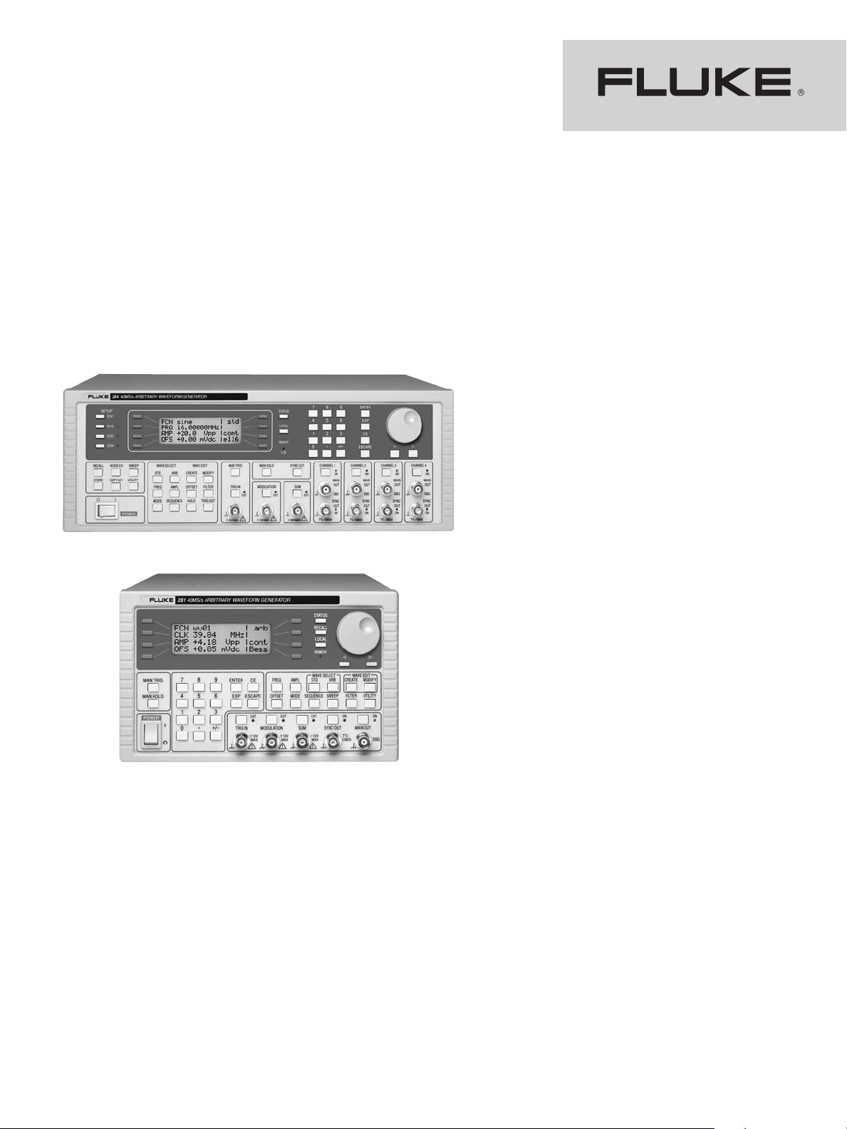
284 Waveform Generator
Key features:
Choice of one, two and four
•
independent or linked channels
40 MS/s max. sampling speed
•
16 MHz function generator
•
10 MHz pulse generator
•
Pulse train pattern generator
•
Arbitrary waveforms of up to
•
65 k points
Powerful modulation capabilities
•
Built-in trigger generators
•
Waveform Manager Plus for
•
Windows
Multiple standard waveforms
•
recalled from internal memory
RS-232 and GPIB interfaces
•
®
software
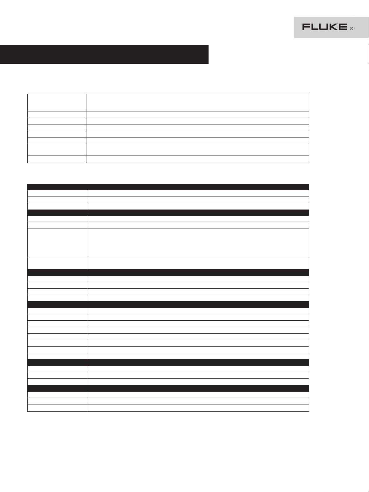
281 Waveform Generator
The 281, 282, and 284 Waveform Generators use
direct digital synthesis techniques as well as variable
clock sampling technolog
programmable function and arbitrary waveform capability. The 281, 282 and 284 are 40 MS/s arbitrary
veform generators w
wa
nels, respectively.
Waveform Manager Plus Software provides all
the features needed for creation, manipulation and
management of arbitrary waveforms within a single
Windows
®
-based program.
y to prov
ith one, two, and four chan-
ide a fully featured
Single or multiple channels
The 28x series c
(281), two-channel (282) and four-channel (284).
Each channel can be operated fully independently,
or multiple channels can b
complex relationships.
omprises a single-channel model
e linked using simple or
Waveforms
Standard wa
dc, positive ramp, negative ramp, sine(x)/x, pulse,
pulse train, c
frequenc
square and up to 100 kHz for triangle, ramps and
sine(x)/x
range of 1
e adjusted from 2.5 mV to 1
b
veforms include: sine, square, triangle,
osine. Output
osine, ha
y range is 0.1 mHz to 16 MHz for sine and
. Rise time for pulse is < 25 ns w
00 ns to 100 s. Output amplitude range can
versine and ha
0 V p-p into 50
verc
ith a period
Ω.
Page 2

Versatile pulse generator capabilities
Each channel can generate not just pulses but complex pulse trains
quickly defined with each pulse having its own amplitude, width and delay. The whole pulse train pattern
can then b
Where variable rise time pulses are required, the full
arbitrary function can be used.
. A pattern of up to 10 pulses can be
e replayed at a user-defined repetition rate.
Arbitrary capability unmatched at this price
The 280 Series are highly sophisticated 12-bit arbitrary generators, capable of recreating virtually any
waveform. True variable clock architecture is used,
with clock speeds between 0.1 Hz and 40 MHz. This
architecture avoids the clock jitter associated with DDS
arbitrary generators and permits waveform linking,
looping and sequencing. Waveforms may be defined
with up to 4,096 vertical points and from 4 to 65,536
horizontal points. Arbitrary waveforms may be
replayed at a specified waveform frequency, period or
sample rate. Up to 100 user-defined waveforms can be
stored within the instrument’s 256 K of nonvolatile
memory.
Linked-sequence operation
Up to sixteen arbitrary waveforms may be linked in a
sequence. Each waveform can have a loop count of up
to 32,768 and the whole sequence can be run continuously or repeated more than a million times. For
multi-channel models, waveforms on different channels can be daisy chained and looped. By summing
the channel outputs, up to 64 segments can be used
to create highly complex waveforms.
Multi-channel phase locking
Any number of channels can be phase locked with
ree (or 360
offsets defined to a resolution of 0.
degrees/waveform points for arbitrary waveforms).
For applications requiring more than four channels,
multiple generators can b
Series also has the facility for phase locking to another
generator.
e phase locked
1 deg
. The 28
0
Multi-channel summing
Waveform summing sums the waveform from any
natively, any
channel into the next channel
er of channels can b
numb
signal. This permits complex modulations, such as
noise superimposition, to b
. Alter
e summed with an external
e created
.
Inter-channel triggering and modulation
Because any channel can be triggered by the previous
or next channel, waveforms on different channels can
be daisy chained and looped. By summing the channel outputs, up to 64 segments can be used (32 segments for 282). A channel can be used to AM
modulate or SCM modulate another channel.
Wide frequency sweep range
veforms can b
All wa
range at a rate variable between 30 milliseconds and
e swept over their full frequency
15 minutes. Sweep can be linear or logarithmic, single
ontinuous. Single sweeps can be triggered from
or c
the front panel, the trigger input, or the digital interfaces. Multiple channels can be swept simultaneously.
Amplitude modulation
Amplitude modulation and suppressed carrier modulation are available for all waveforms. Any channel can
be used to modulate another channel. Alternatively, all
channels can be modulated simultaneously via the
modulation input.
Built-in trigger generator
All waveforms are available as a triggered burst,
whereby each trigger edge will produce one burst of
the carrier. Start and stop phase is fully variable. Both
triggered and gated modes can be operated from the
internal trigger generator, from an adjacent channel,
an external source or a key press or remote command.
The trigger generator signal is available as a separate
output if required.
Tone switching
The 280 Series can provide triggered switching
between up to 16 frequencies of standard or arbitrary
waveforms. Tone switching modes can be gated, triggered or FSK using any trigger source. By summing
two channels together it is possible to generate precise DTMF test signals.
Windows®-based waveform editing
Each generator is supplied complete with sophisticated Windows-based software for the creation, editing and management of waveforms. This powerful
software can be used to create arbitrary waveforms
from scratch using drawing tools, equations or both
together. Real-world waveforms imported from DSOs
or other sources can be modified and combined with
other waveforms using editing functions. A library of
standard waveforms is included which can be used as
elements
“
powerful Equation Editor prov
matical functions, including logarithmic and geometric
operands
use of draw
insertion and manipulation. Multiple waveforms can
e further c
b
create new wa
” when creating or modif
veform creation and editing can make
a
. W
ing tools in c
ombined using mathematical operators to
veforms
ombination with equations,
.
ying wa
ides an arra
veforms
y of mathe-
. A
Import from DSOs and other instruments
The Windows software incorporates direct support for
uploading waveforms from Tektronix digital oscilloscopes. A driver for LabWindows
Instruments is available which enables imports from
other equipment to be achieved within the LabWindows environment.
™/CVI from National
Fully programmable via RS-232 or GPIB
The 280 Series incorporates both an RS-232 interface
and a GPIB (IEEE-488) interface as standard. These
e used for loading arbitrar
can b
remote control of all instrument functions.
y waveforms and for
2 Fluke Corporation 280 Series Waveform Generators
Page 3
280 Series Specifications
Specifications apply at 18 °C to 28 °C after 30 minutes warm-up, at maximum output into 50 Ω.
Arbitrary waveforms
Waveforms Maximum waveform size is 65,536 points; minimum waveform size is 4 points. Up to 100 user defined
aveform memory 64 k points per channel
W
ertical resolution 12 bits
V
Sample clock
Resolution
Accuracy ± 1 digit of setting
ing Up to 16 waveforms may be linked. Each waveform can have a loop count of up to 32,768. A sequence of
Sequenc
Output filter
Standard waveforms
All Waveforms
curacy 10 ppm for 1 year
Ac
Temp. stability Typically < 1 ppm/ºC.
Output level 2.5 mV to 10 Vpp into 50 Ω
Sine, Cosine, Haversine, Havercosine
Range 0.1 mHz to 16 MHz
Resolution 0.1 mHz or 7 digits
Harmonic distortion < 0.1 % THD to 100 kHz;
Nonharmonic spurii < –65 dBc to 1 MHz,
Square
Range 1 mHz to 16 MHz
Resolution 1 mHz (4 digits)
Accuracy ± 1 digit of setting
Rise/fall times < 25 ns
Pulse and Pulse T
Rise/fall times
eriod range
P
eriod resolution
P
y
curac
Ac
y range
ela
D
Delay resolution 0.002 % of period or 25 ns, whichever is greater
Width range 25 ns to 99.99 s
Width resolution 0.002 % of period or 25 ns, whichever is greater
riangle
T
Range
Resolution
inearity error
L
Ramps and Sin(x)/x
Range
Resolution
inearity error
L
Note: The pulse width and absolute value of the delay may not exceed the pulse period at any time. Pulse trains of up to 10 pulses may be specified, each pulse having independently defined width, delay and level. The baseline voltage is separately defined and the sequence repetition
rate is set by the pulse train period.
rain
waveforms may be stored in the 256 K point nonvolatile RAM. Waveforms can be defined by front panel editing
controls or by downloading of waveform data via RS-232 or GPIB.
100 mHz to 40 MHz
4 digits
veforms can be looped up to 1,048,575 times or run continuously.
wa
Selectable between 16 MHz Elliptic, 10 MHz Elliptic, 10 MHz Bessel or none
< –65 dBc to 20 kHz,
< –50 dBc to 300 kHz,
< –35 dBc to 10 MHz
< –30 dBc to 16 MHz
< –65 dBc + 6 dB/octave 1 MHz to 16 MHz
< 25 ns
00 ns to 1
1
4 dig
±
–99.99 s to + 99.99 s
0.
0.
< 0.
0.
0.
0.
00 s
it
it of setting
1 dig
1 mHz to 1
1 mHz or 7 dig
1 mHz to 100 kHz
1 mHz (7 dig
1 % to 30 kHz
00 kHz
its
1 % to 30 kHz
its)
3 Fluke Corporation 280 Series Waveform Generators
Page 4

280 Series Specifications cont.
Operating modes
Continuous
Waveform runs continuously
Triggered Burst
Each active edge of the trigger sig
Carrier waveforms All standard and arbitrary
. Carrier Frequency 40 Ms/s for ARB and Sequence. 1 MHz or the maximum for the selected waveform.
Max
er of cycles 1 to 1,048,575
Numb
Trigger repetition 0.005 Hz to 100 kHz internal dc to 1 MHz external
Trigger sig
Trigger start/stop phase ± 360 ° settable with 0.1 ° resolution, subject to waveform frequency and type
Gated
W
Carrier waveforms All standard and arbitrary
Max
Number of cycles 1 to 1,048,575
Trigger repetition 0.005 Hz to 100 kHz internal dc to 1 MHz external
Gate signal source Internal from keyboard, previous channel, next channel or trigger generator. External from TRIG IN or
Gate start/stop phase ± 360 ° settable with 0.1 ° resolution, subject to waveform frequency and type
Tone Switching
Frequency sweep capability is provided for both standard and arbitrary waveforms. Arbitrary waveforms are expanded or condensed to
exactly 4096 points and DDS techniques are used to perform the sweep.
Carrier waveforms All standard and arbitrary except pulse, pulse train and sequence
Sweep mode Linear or logarithmic, triggered or continuous
Sweep direction Up, down, up/down or down/up
Sweep range From 1 mHz to 16 MHz in one range. Phase continuous. Independent setting of the start and stop frequency.
Sweep time 30 ms to 999 s
Marker Variable during sweep
Sweep trigger source The sweep may be free run or triggered from the following sources: Manually from keyboard.
Sweep hold Sweep can be held and restarted by the HOLD key
Multi channel sweep Any number of channels may be swept simultaneously but the sweep parameters will be the same for all
Tone Switching
Capability prov
D
Carrier waveforms All except pulse, pulse train and sequence
Frequency list Up to 16 frequencies from 1 mHz to 10 MHz
Trigger repetition rate 0.005 Hz to 100 kHz internal. DC to 1 MHz external. Usable repetition rate and waveform frequency depend
Source Internal from keyboard, previous channel, next channel or trigger generator. External from TRIG IN or
Tone switching modes
Gated The tone is output while the trigger signal is true and stopped, at the end of the current waveform cycle,
Triggered The tone is output when the trigger signal goes true and the next tone is output, at the end of the current
FS
Trigger Generator
Internal source 0.005 Hz to 100 kHz square wave adjustable in 10 us steps. 3-digit resolution. Available for external use from any
SYNC OUT socket.
nal source Internal from keyboard, previous channel, next channel or trigger generator. External from TRIG IN or remote
aveform will run while the Gate signal is true and stop while false
. carrier frequency 40 Ms/s for ARB and Sequence. 1 MHz or the maximum for the selected waveform.
ided for both standard and arbitrary waveforms. Arbitrary waveforms are expanded or condensed to exactly 4096 points and
DS techniques are used to allow instantaneous frequency switching.
K The tone is output when the trigger signal goes true and the next tone is output, immediately, when the
nal will produce one burst of the waveform
e.
interfac
remote interface.
Externally from TRIG IN input or remote interface.
channels. Amplitude, Offset and Waveform can be set independently for each channel.
on the tone switching mode.
remote interface.
while the trigger signal is false. The next tone is output when the trigger signal is true again.
waveform cycle, when the trigger signal goes true again.
trigger sig
D
nal goes true again. Using 2 channels with their outputs summed together it is possible to generate
TMF test signals.
4 Fluke Corporation 280 Series Waveform Generators
Page 5

280 Series Specifications cont.
Outputs
Main Output — One for each channel
Output impedanc
Amplitude 5 mV to 20 Vpp open circuit (2.5 mV to 10 Vpp into 50 Ω). Amplitude can be specified open circuit (hi Z) or
Amplitude ac
Amplitude flatness ± 0.2 dB to 200 kHz; ± 1 dB to 10 MHz; ± 2.5 dB to 16 MHz
C offset range ± 10 V from 50
D
DC offset accuracy Typically 3 % ± 10 mV, unattenuated
Resolution
Sync Out — One for each channel
Multifunction output user definable or automatically selected to b
Waveform sync A square wave with 50 % duty cycle at the main waveform frequency, or a pulse coincident with the first few
(all waveforms) points of an arbitrary waveform.
osition markers Any point(s) on the waveform may have associated marker bit(s) set high or low
P
Burst done Produces a pulse coincident with the last cycle of a burst.
Sequenc
Trigger
Sweep sync Outputs a pulse at the start of sweep to synchronize an oscilloscope or recorder.
Phase lock out
Output sig
Cursor/marker out Adjustable output pulse for use as a marker in sweep mode or as a cursor in arbitrary waveform editing mode.
Output impedance 600
e 50
curacy 2 % ± 1 mV at 1 kHz into 50
e sync Produces a pulse coincident with the end of a waveform sequence.
nal level TTL/CMOS logic levels from typically 50
Ω
into an assumed load of 50 Ω or 600 Ω Vp-p, Vrms or dBm.
Ω
Ω. Offset plus sig
3 digits or 1 mV for both amplitude and dc offset
Selects the current trigger signal. Useful for synchronizing burst or gated signals.
Used to phase lock two generators. Produces a positive edge at the 0 ° phase point.
Can be used to modulate the Z axis of an oscilloscope or be displayed on a second ‘scope channel.
Output Signal Level: Adjustable from nominally 2 V to 14 V, normal or inverted; adjustable width as a cursor.
Ω typical
nal peak limited to ± 10 V
e any of the following:
Ω.
Inputs
Trig In
Frequency range DC to 1 MHz
Signal range Threshold nominally TTL level; maximum input ± 10 V
Min. pulse width 50 ns, for Trigger/Gate; 50 us for Sweep mode
Polarity Selectable as high/rising edge or low/falling edge
Input impedance 10 kΩ
Modulation In
Frequency range DC to 100 kHz
A signal range Approximately 1 V pkpk for 100 % level change at maximum output
VC
SCM signal range Approximately ± 1 V pk for maximum output
Input impedance Typically 1 kΩ
Sum In
C to 8 MHz
y range
Frequenc
nal range
Sig
Input impedanc
Hold
Holds an arbitrar
wait until a T
y also be used to control the Hold function. While held the front panel MAN TRIG key or remote command may be used to return the
ma
veform to the start. The Hold input may be enabled independently for each channel.
wa
Input impedanc
Ref Clock In/Out
Set to input Input for an external 10 MHz reference clock. TTL/CMOS threshold level.
Set to output
Set to phase lock
e
y waveform at its current position. A TTL low level or switch closure causes the waveform to stop at the current position and
TL high level or switch opening which allows the waveform to continue. The front panel MAN HOLD key or remote command
e10 k
D
Approximately 2 V p-p input for 20 V p-p output
Typically 1 k
Buffered version of the internal 10 MHz clock. Output levels nominally 1 V and 4 V from 50
Used together with SYNC OUT on a master and TRIG IN on a slave to synchronise (phase lock) two separate
generators
Ω
Ω
Ω
.
5 Fluke Corporation 280 Series Waveform Generators
Page 6

280 Series Specifications cont.
Inter-channel operation
Inter-Channel Modulation
The waveform from any channel may be used to Amplitude Modulate (AM) or Suppressed Carrier Modulate (SCM) the next channel.
Alternatively any number of channels may be Modulated (AM or SCM) with the signal at the MODU LATION input socket.
Carrier frequenc
Carrier waveforms All standard and arbitrary waveforms
Modulation types
Modulation source Internal from the previous channel. External from Modulation input socket. The external modulation signal
Frequency range DC to > 100 kHz
nal AM depth 0 % to 105 %.
Inter
Internal AM resolution 1 %
Carrier suppression (S
External modulation VCA: Approximately 1 V p-p for 100 % level change at maximum output
signal range SCM: Approximately ± 1 V pk for max. output
Inter-Channel Analogue Summing
Waveform Summing sums the waveform from any channel into the next channel. Alternatively any number of channels may be summed with
the signal at the SUM input socket.
Carrier frequency Entire range for selected waveform
Carrier wa
Sum sourc
Frequency range DC to > 8 MHz
Ext. signal range Approx. 5 V p-p input for 20 V p-p output
Inter-Channel Phase Locking
Two or more channels may be phase locked together. Each locked channel may be assigned a phase angle relative to the other locked
channels. Arbitrary waveforms and waveform sequences may be phase locked but certain constraints apply to waveform lengths and clock
frequency ratios. With one channel assigned as the Master and other channels as Slaves a frequency change on the master will be repeated
on each slave thus allowing multiphase waveforms at the same frequency to be easily generated. DDS waveforms are those with 7 digits of
frequency setting resolution, while Non-DDS waveforms have 4 digits.
Phase resolution DDS waveforms: 0.1 degree or 360 degrees/number of points whichever is the greater
Non-DDS waveforms
Phase error < ± 10 ns all waveforms
Inter-Channel Triggering
Any channel can be triggered by the previous or next channel. The previous/next connections can be used to ‘daisy chain’ a trigger signal
from a ‘start’ channel, through a number of channels in the ‘chain’ to an ‘end’ channel. Each channel receives the trigger out signal from the
previous (or next) channel, and drives its selected trigger out to the next (or previous) channel. The ‘end’ channel trigger out can be set up to
drive the ‘start’ channel, closing the loop. In this way, complex and versatile interchannel trigger schemes may be set up. Each channel can
have its trigger out and its output waveform set up independently. Trigger out may be selected from Waveform End, Position Markers,
Sequence Sync or Burst Done. Using the scheme above it is possible to create a sequence of up to 64 waveform segments, each channel
producing up to 16 segments and all channels being summed to produce the complete waveform at the output of channel 4.
y Entire range for selected waveform
AM: Double sideband with carrier. SCM: Double sideband suppressed carrier
y be applied to any number of channels simultaneously.
ma
CM) > 40 dB
veforms All standard and arbitrary waveforms
e Internal from the previous channel. External from SU M IN socket.
The signals from the REF IN/OUT socket and the SYNC OUT socket can be used to phase lock two instruments
where more than 4 channels are required.
Interfaces
RS-232 Variable Baud rate, 9600 Baud maximum
IEEE-488 Conforms with IEEE488.1 and IEEE488.2
Software included Windows®-based software for waveform creation, editing and management is supplied.
Instrument drivers LabView and LabWindows CVI drivers are either supplied with the instrument or are available via your local
6 Fluke Corporation 280 Series Waveform Generators
Fluke office
Page 7

280 Series Specifications cont.
General Specifications
Display 20 character x 4 row alphanumeric LCD
Data entry Keyboard selection of mode, waveform etc.; value entry direct by numeric keys or by rotary control
Stored settings
Size 130 mm (3 U) height; 335 mm long; width 350 mm (282/284), 212 mm (281)
eight 7.2 kg. (16 lb) (282/284); 4.1 kg (9 lb) (281)
W
Power 230 V, 115 V or 100 V nominal 50/60 Hz, adjustable internally; operating range ± 14 % of nominal;100 VA max.
Operating range
Storage range –20 °C to + 60 °C
Environmental Indoor use at altitudes to 2000 m, Pollution Degree 2
Options
Safety Complies with EN61010-1
MC Complies with EN61326
E
Up to 9 complete instrument setups may be stored and recalled from battery-backed memory.
00 arbitrary waveforms can also be stored independent of the instrument settings.
Up to 1
for 4 channels, 75 VA max. for 2 channel, 40 VA max. for 1 channel. Installation Category II.
+5 °C to 40 °C, 20-80 % RH
19-in rack mounting kit
Ordering
Information
Models
281 1 Channel 40 MS/s Arbitrary
Waveform Generator and
Waveform Manager Plus Software
282 2 Channel, 40 MS/s
Arbitrary Waveform Generator and
Waveform Manager Plus Software
284 4 Channel, 40 MS/s
Arbitrary Waveform Generator and
Waveform Manager Plus Software
Options and
Accessories
Y200H Rack
mount K
(281)
Y200F Rackmount Kit – full rack
(282, 284)
it – half rack
7 Fluke Corporation 280 Series Waveform Generators
eping your world
Fluke. K
e
up and running.
Fluke Corporation
PO Box 9090, Everett, WA USA 98206
Fluke Europe B.V.
PO Box 1186, 5602 BD
Eindhoven, The Netherlands
e information call:
or mor
F
In the U.S.A. (800) 443-5853 or
Fax (425) 446-5116
In Europe/M-East/Africa (31 40) 2 675 200 or
ax (31 40) 2 675 222
F
In Canada (8
ax (9
F
From other countries +1 (425) 446-5500 or
Fax +1 (425) 446-5116
eb ac
W
©2005 Fluke Corporation. All rights reserved.
Printed in U.S.A. 9/2005 2523650 D-EN-N Rev B
00)-360-6866
05) 89
cess: http://www.fluke.com/
KE or
LU
F
 Loading...