

Page 1

®
2680A/2686A
Data Acquisition System/Data Logging System
June 2002, Rev. 1, 4/04
© 2002, 2004 Fluke Corporation. All rights reserved.
All product names are trademarks of t heir resp ective co mpani es.
Users Manual
Page 2

Limited Warranty and Limitation of Liability
Each Fluke product is warranted to be free from defects in material and workmanship under normal
use and service. The warranty period is one year and begins on the date of shipment. Parts, product
repairs and services are warranted for 90 days. This warranty extends only to the original buyer or
end-user customer of a Fluke authorized reseller, and doe s not appl y to fuses, di spo sab le batteries
or to any product which, in Fluke's opinion, has been misused, altered, neglected, contaminated, or
damaged by accident or abnormal condit ion s of operatio n or handling .
Fluke warrants that software will operate substantially in accordance with its functional specifications
for 90 days and that it has been properly recorded on non-defective media. Fluke does not warrant
that software will be error free or operate without interruption. The software is neither intended nor
warranted for use in medical or any other applications where human safety may be a concern.
Fluke authorized resellers shall extend this warranty on new and unused products to end-user
customers only but have no authority to extend a greater or different warranty on behalf of Fluke.
Warranty support is available only if product is purchased through a Fluke authorized sales outlet or
Buyer has paid the applicable international price. Fluke reserves the right to invoice Buyer for
importation costs of repair/replacement parts when product purchased in one country is submitted for
repair in another country.
Fluke's warranty obligation is limited, at Fluke's option, to refund of the purchase price, free of charge
repair, or replacement of a defective product which is returned to a Fluke authorized service center
within the warranty period.
To obtain warranty service, contact your nearest Fluke authorized service center to obtain return
authorization information, then send the product to that service center, with a description of the
difficulty, postage and insurance prepaid (FOB Destination). Fluke assumes no risk for damage in
transit. Following warranty repair, the product will be returned to Buyer, transportation prepaid (FOB
Destination). If Fluke determines that failure was caused by neglect, misuse, contamination,
alteration, accident or abnormal condition of operation or handling, including over vo ltage failures
caused by use outside the product’s specified rating, or normal wear and tear of mechanical
components, Fluke will provide an estimate of repair costs and obtain authorization before
commencing the work. Following repair, the product will be returned to the Buyer transportation
prepaid and the Buyer will be billed for the repair and return transportation charges (FOB Shipping
Point).
THIS WARRANTY IS BUYER'S SOLE AND EXCLUSIVE REMEDY AND IS IN LIEU OF ALL
OTHER WARRANTIES, EXPRESS OR IMPLIED, INCLUDING BUT NOT LIMITED TO ANY
IMPLIED WARRANTY OF MERCHANTABILITY OR FITNESS FOR A PARTICULAR PURPOSE.
FLUKE SHALL NOT BE LIABLE FOR ANY SPECIAL, INDIRECT, INCIDENTAL OR
CONSEQUENTIAL DAMAGES OR LOSSES AND/OR PROFITS, INCLUDING LOSS OF DATA,
ARISING FROM ANY CAUSE OR THEORY.
Since some countries or states do not allow limitation of the term of an implied warranty, or exclusion
or limitation of incidental or consequential damages, the limitations and exclusions of this warranty
may not apply to every buyer. If any provision of this Warranty is held invalid or unenforceable by a
court or other decision-maker of competent jurisdiction, such holding will not affect the validity or
enforceability of any other provision.
Fluke Corporation Fluke Europe B.V.
P.O. Box 9090 P.O. Box 1186
Everett, WA 98206-9090 5602 BD Eindhoven
U.S.A. The Netherlands
2/02
Page 3

XWCaution
This is an IEC safety Class 1 product. Before using, the
ground wire in the line cord or rear panel binding post
must be connect to an earth ground for safety.
Interference Information
This equipment generates and uses radio frequency energy and if not installed and used in strict
accordance with the manufacturer’s instructions, may cause interference to radio and television
reception. It has been type tested and found to comply with the limits for a Class B computing device
in accordance with the specifications of Part 15 of FCC Rules, which are designed to provide
reasonable protection against such interference in a residential installation.
Operation is subject to the following two conditions:
• This device may not cause harmful interfere nce .
• This device must accept any interference received, including interference that may cause
undesired operation.
There is no guarantee that interference will not occur in a particular installation. If this equipment
does cause interference to radio or television reception, which can be determined by turning the
equipment off and on, the user is encouraged to try to correct the interference by one of more of the
following measures:
• Reorient the receiving antenna
• Relocate the equipment with respect to the receiver
• Move the equipment away from the receiver
• Plug the equipment into a different outlet so that the computer and receiver are on different
branch circuits
If necessary, the user should consult the dealer or an experienced radio/television technician for
additional suggestions. The user may find the following booklet prepared by the Federal
Communications Commission helpful: How to Identify and Resolve Radio-TV Interference Problems.
This booklet is available from the U.S. Government Printing Office, Washington, D.C. 20402. Stock
No. 004-000-00345-4.
Page 4

SAFETY TERMS IN THIS MANUAL
This device has been designed and tested to meet the requirements of EN61010-1
(Safety Requirements for Electrical Equipment for Measurement, Control and
Laboratory Use). It is an Installation Category II device intended for operation from
a normal single phase supply. The DIO relay controls are rated to 250 V ac CAT I
and should not be used in applications that exceed that rating.
contains information, warnings and cautions. Use of this equipment in a manner
not specified herein may impair the protection provided by the equipment.
Measurement category I is for measurements performed on circuits not directly
connected to MAINS. Examples are measurements on circuits not derived from
MAINS, and specially protected (internal) MAINS derived circuits.
Measurement category II is for measurements performed on circuits directly
connected to the low voltage installation. Examples are measurements on
household appliances, portable tools and similar equipment.
XWWARNING statements identify conditions or practices that could result in
personal injury or loss of life.
XWCAUTION statements identify conditions or practices that could result in
damage to equipment.
SYMBOLS MARKED ON EQUIPMENT:
This Users Manual
X WARNING Risk of electric shock.
J Ground (earth) terminal.
.
W
AC POWER SOURCE
The device is intended to operate from an ac power source that will not apply more
than 264 V ac rms between the supply conductors or between either supply
conductor and ground. A protective ground connection by way of the grounding
conductor in the power cord is required for safe operation.
Protective ground (earth) terminal. Must be connected to safety earth
ground when the power cord is used.
Attention. Refer to the manual. This symbol indicates that information
about usage of a feature is contained in the manual. This symbol
appears on the Universal Input Module and in the following two places
on the device rear panel:
1. Ground Binding Post (to the left of the line power connector).
2. Alarm/Trigger I/O and Digital I/O connectors.
Page 5

XWWARNING
Use the proper fuse. To avoid fire hazard, for fuse
replacement use only a 1/2 ampere, 250 V time delay line
fuse.
DC POWER SOURCE
The device may also be operated from a 9 V to 45 V dc power source when either
the rear panel ground binding post or the power cord grounding conductor is
connected properly. The input is protected by a 4 ampere fuse internal to the
device. This fuse should only be replaced by a qualified Fluke technician.
GROUNDING THE DEVICE
The device utilizes controlled overvoltage techniques that require the device to be
grounded whenever normal mode or common mode ac voltages or transient
voltages may occur. The enclosure must be grounded through the grounding
conductor of the power cord, or if operated on battery with the power cord
unplugged, through the rear panel ground binding post.
USE THE PROPER POWER CORD
Use only the power cord and connector appropriate for the voltage and plug
configuration in your country.
Use only a power cord that is in good condition.
Refer power cord and connector changes to qualified service personnel.
XWWARNING
To avoid possible electric shock or damage to the device:
• Read manual before operating.
• Do not position device so that air flow through side
vents is restricted.
• Do not use in a manner not specified in this manual or
safety protection may be impaired.
• Disconnect power cord and ALL other inputs before
replacing a fuse.
• Position the device where power cord can be
disconnected.
• Do not exceed maximum voltages.
Page 6

XWWARNING
• Do not operate in explosive atmospheres.
• To avoid personal injury or death, do not remove the
device cover without first removing the power source
connected to the rear panel. Do not operate the device
without the cover properly installed. There is no need
for the operator to remove the cover.
• Do not attempt to operate if protection may be
impaired.
• If the device appears damaged or operates abnormally,
protection may be impaired. Do not attempt to operate
the device under these conditions. Refer all question
of proper device operation to qualified service
personnel.
• Do not attempt to service unless you are a Fluke
qualified repair technician.
• To avoid personal injury or death, remove the AC
power cord and all analog and digital connector
modules before servicing the device.
Note
All signals must be removed from the analog and digital connector
wiring before opening the connector modules.
Page 7

The following table provides additional safety information.
General Specifications
Specification Characteristic
Size 473 mm (18.6 in) x 432 mm (17 in) x 237 mm (9.3 in)
Weight 2680A/2686A (empty) 8.6 Kg (18.9 lb)
2680A – FAI 0.8 Kg (1.8 lb)
2680A – PAI 1.2 Kg (2.7 lb)
2680A – DIO 0.8 Kg (1.8 lb)
Power 100 – 240 V ac (no switching required), 50 to 60 Hz, 100 VA
maximum or optional 9 V d c to 45 V dc, 35 W maximum
EMC EN50082-2
EN55022-1
EN55011 class A
EN610000-4-2,3,4,6,8
EN61326
Safety EN61010-1, CAT II
CSA C22.2 No. 1010.1
Operating Temperature
-20 oC to 60 oC (-4 oF to +140 oF)
Range
Storage Temperature
-40 oC to 70 oC (-40 oF to +158 oF)
Range
Relative Humidity 90% maximum for -10 oC to 28 oC (14 oF to +82 oF)
75% maximum for 28
50% maximum for 35
o
C to 35 oC (82 oF to +95 oF)
o
C to 60 oC (95 oF to +140 oF)
(3 MΩ range, reduce humidity rating by 25% for 1 hour warm-up.
3 MΩ range meets full humidity ratings with 2 hour warm-up)
Altitude Operating: 2,000 m (6,562 ft) maximum
Non-operating: 12,200 m (40,000 ft) maximum
Page 8

Page 9

Table of Contents
Chapter Title Page
1 Overview........................................................................................... 1-1
Introduction...................................................................................................... 1-3
Contacting Fluke.............................................................................................. 1-3
Instrument Features and Capabilities............................................................... 1-5
Mainframe Features................................................................................... 1-8
Trigger Input......................................................................................... 1-8
Trigger Output ...................................................................................... 1-8
PC Card ATA Interface (2686A Only)................................................. 1-8
Master Alarm ........................................................................................ 1-9
Interval Trigger..................................................................................... 1-9
External Trigger.................................................................................... 1-9
Alarms................................................................................................... 1-9
Channel Monitoring.............................................................................. 1-10
Alarm Trigger ....................................................................................... 1-10
Channel Numbering .................................................................................. 1-10
Computed Channels .................................................................................. 1-11
Mx+B Scaling ........................................................................................... 1-11
Analog Channels ....................................................................................... 1-11
Digital I/O Module Option........................................................................ 1-12
Digital I/O............................................................................................. 1-12
Relay Output......................................................................................... 1-12
Totalizer................................................................................................ 1-12
User Interface................................................................................................... 1-13
Operating a 2680 Series Data Acquisition System.......................................... 1-14
Isolated Networks...................................................................................... 1-14
General Networks...................................................................................... 1-14
Ethernet Port.............................................................................................. 1-14
Group Operations...................................................................................... 1-15
Scanning and Logging............................................................................... 1-15
RS-232 Interface ....................................................................................... 1-17
i
Page 10

2680A/2686A
Users Manual
Host Computer Requirements......................................................................... 1-17
Options and Accessories ................................................................................. 1-18
2 Preparing for Operation................................................................... 2-1
Introduction..................................................................................................... 2-3
Instrument Preparation.................................................................................... 2-4
Unpacking and Inspecting the Instrument ................................................ 2-5
Positioning and Rack Mounting ............................................................... 2-5
Connecting to a Power Source and Grounding......................................... 2-5
Operating Using AC Power.................................................................. 2-6
Operating Using DC Power.................................................................. 2-7
Grounding and Common Mode Voltage.............................................. 2-7
Alarm/Trigger I/O Connection ................................................................. 2-7
Trigger Input......................................................................................... 2-8
Trigger Output...................................................................................... 2-9
Master Alarm........................................................................................ 2-10
External Trigger Wiring for a Group........................................................ 2-10
Universal Input Module Analog Connections (2620A-180)..................... 2-12
Shielded Wiring.................................................................................... 2-15
Crosstalk Considerations...................................................................... 2-15
Digital I/O Connector Module.................................................................. 2-15
Digital I/O............................................................................................. 2-16
Totalizer................................................................................................ 2-16
Totalizer Enable ................................................................................... 2-17
Relays ................................................................................................... 2-17
Controls and Indicators............................................................................. 2-17
Front Panel Controls............................................................................. 2-17
Front Panel Indicators .......................................................................... 2-19
Rear Panel Controls.............................................................................. 2-22
Rear Panel Indicators............................................................................ 2-23
Front Panel Operating Procedures ............................................................ 2-24
Power-On Options................................................................................ 2-24
Displaying a Monitor Channel ............................................................. 2-25
Displaying the Digital I/O Status ......................................................... 2-27
Displaying Relay Status ....................................................................... 2-28
Displaying the Totalizer Status ............................................................ 2-30
Reviewing and Setting the Base Channel Number............................... 2-31
Reviewing and Setting the Line Frequency.......................................... 2-33
Reviewing and Setting the Network Type............................................ 2-35
Reviewing and Setting the General Network Socket Port.................... 2-40
Reviewing and Setting the General Network IP Address..................... 2-41
Reviewing and Setting the Subnet Mask and Default Gateway........... 2-42
Viewing the Instrument Ethernet Address ........................................... 2-44
Reviewing and Setting PC Card Options ............................................. 2-46
ii
Page 11

Contents
(continued)
Host Computer and Network Preparation........................................................ 2-47
Installing Host Computer Ethernet Adapter.............................................. 2-47
Instrument and Host Computer Interconnection ....................................... 2-49
Host Computer/Instrument Direct Connection ..................................... 2-49
Interconnection Using 10/100BaseT (Twisted Pair) Ethernet Wiring.. 2-50
Set Up Windows Networking ................................................................... 2-52
Setting Host Computer Networking Parameters ....................................... 2-53
Installing Fluke DAQ Software................................................................. 2-53
Testing and Troubleshooting ........................................................................... 2-54
Installing and Testing the Installation ....................................................... 2-54
Troubleshooting Network Problems ......................................................... 2-58
3 Using Fluke DAQ Software .............................................................. 3-1
Introduction...................................................................................................... 3-3
Installing Fluke DAQ Software ....................................................................... 3-4
Understanding the User Interface .................................................................... 3-5
Fluke DAQ Main Window........................................................................ 3-5
Using the Toolbar...................................................................................... 3-6
Understanding the Workspace Area.......................................................... 3-8
Configuration Dialogs............................................................................... 3-9
Main Configuration Dialog................................................................... 3-9
Instrument Configuration Dialog.......................................................... 3-9
Module Configuration Dialog............................................................... 3-10
Analog Channel Configuration Dialog ................................................. 3-10
DIO Configuration Dialog.................................................................... 3-10
Computed Channel Configuration Dialog ............................................ 3-10
Communication Dialogs............................................................................ 3-11
Main Communication Dialog ............................................................... 3-11
Instrument Communication and Status Dialog..................................... 3-11
Module Communication Dialog ........................................................... 3-11
Digital I/O Points Dialog...................................................................... 3-11
Computed Channels Dialog.................................................................. 3-11
Communications Icons.......................................................................... 3-12
Security Dialogs........................................................................................ 3-12
Trend Dialog ............................................................................................. 3-13
Alarm Dialog............................................................................................. 3-13
Mail and Web Settings Dialogs................................................................. 3-13
Managing Your Network Using Fluke DAQ................................................... 3-14
Inserting and Configuring an Instrument .................................................. 3-14
Inserting and Configuring a Module ......................................................... 3-19
Inserting and Configuring a Channel ........................................................ 3-23
Configuring a Computed Channel............................................................. 3-26
Configuring Multiple Channels................................................................. 3-29
Using Equations with Computed Channels............................................... 3-30
iii
Page 12

2680A/2686A
Users Manual
Configuring Data Files.................................................................................... 3-46
Main Window Advanced Settings................................................................... 3-55
Using Fluke DAQ System Security Features.................................................. 3-56
Configuring Web and Alarm Mail Settings .................................................... 3-58
Starting a Scan .......................................................................................... 3-32
Starting a Configuration Scan .............................................................. 3-32
Starting an Instrument Scan.................................................................. 3-33
Getting Scan Data................................................................................. 3-33
Viewing and Resetting the Totalizer .................................................... 3-34
PC Card Functions.................................................................................... 3-34
Getting PC Card Information ............................................................... 3-34
Formatting the PC Card........................................................................ 3-34
Getting PC Card Scan Data.................................................................. 3-35
Starting Spy .............................................................................................. 3-36
Viewing Module Measurement Data........................................................ 3-38
Using the Digital I/O Points Communication Dialog............................... 3-39
Using Trend to View Collected Data........................................................ 3-40
Changing the Trend Chart Display....................................................... 3-43
Viewing Alarms........................................................................................ 3-44
Selecting a Master for a Data Group......................................................... 3-47
Advanced Data File Configuration........................................................... 3-47
Real-time Data File Creation .................................................................... 3-53
4 Maintenance ..................................................................................... 4-1
Introduction..................................................................................................... 4-3
Self-Test Diagnostics and Error Codes ........................................................... 4-3
Cleaning .......................................................................................................... 4-6
AC Fuse Replacement..................................................................................... 4-7
DC Fuse Replacement..................................................................................... 4-9
Performance Test............................................................................................. 4-9
Configuring the Performance Test Setup.................................................. 4-9
Initializing the Performance Test Setup.................................................... 4-11
Accuracy Performance Tests........................................................................... 4-13
Master Alarm Output Tests....................................................................... 4-14
RS-232 Master Alarm Output Test....................................................... 4-14
Fluke DAQ Master Alarm Output Test................................................ 4-14
Trigger Input Tests ................................................................................... 4-15
RS-232 Trigger Input Test.................................................................... 4-15
Fluke DAQ Trigger Input Test............................................................. 4-15
Trigger Output Tests................................................................................. 4-15
RS-232 Trigger Output Test................................................................. 4-15
Fluke DAQ Trigger Output Test .......................................................... 4-16
Volts DC Accuracy Test (PAI Module).................................................... 4-16
Volts DC Accuracy Test (FAI Module).................................................... 4-17
iv
Page 13

Contents
(continued)
Volts AC Accuracy Test ........................................................................... 4-18
Frequency Accuracy Test.......................................................................... 4-19
Analog Channel Integrity Test .................................................................. 4-20
Open Thermocouple Response Test.......................................................... 4-20
2-Wire Resistance Accuracy Test (PAI) - Optional.................................. 4-21
2-Wire Resistance Accuracy Test (FAI Module) - Optional..................... 4-22
4-Wire Resistance Accuracy Test (PAI Module)...................................... 4-24
4-Wire Resistance Accuracy Test (FAI Module)...................................... 4-28
Digital Input/Output Tests......................................................................... 4-29
RS-232 Digital Input/Output Test......................................................... 4-29
Fluke DAQ Digital Input/Output Test .................................................. 4-30
DIO Relay/Fuse Tests ............................................................................... 4-30
RS-232 DIO Relay Fuse Test ............................................................... 4-30
Fluke DAQ DIO Relay Fuse Test......................................................... 4-30
Totalizer Tests........................................................................................... 4-31
RS-232 Totalizer Count Test ................................................................ 4-31
RS-232 Totalizer Count and Enable Test ............................................. 4-31
RS-232 Totalizer Count and Direction Test ......................................... 4-32
RS-232 Totalizer Count and Debounce Test ........................................ 4-32
Fluke DAQ Totalizer Count Test.......................................................... 4-33
Fluke DAQ Totalizer Count and Enable Test....................................... 4-33
Fluke DAQ Totalizer Count and Direction Test................................... 4-34
Fluke DAQ Totalizer Count and Debounce Test.................................. 4-34
Calibration ....................................................................................................... 4-35
Variations in the Display ................................................................................. 4-35
Service ............................................................................................................. 4-36
Replacement Parts ........................................................................................... 4-36
Appendices
A Specifications ............................................................................................ A-1
B Noise, Shielding, and Crosstalk Considerations ....................................... B-1
C True-RMS Measurements ......................................................................... C-1
D RTD Linearization..................................................................................... D-1
E Computed Channel Equations................................................................... E-1
F Data File Format........................................................................................ F-1
G Ethernet Cabling........................................................................................ G-1
H Network Considerations............................................................................ H-1
I Error Codes ............................................................................................... I-1
v
Page 14

2680A/2686A
Users Manual
vi
Page 15

List of Tables
Table Title Page
1-1. Channel Count vs Scan Rate............................................................................ 1-16
1-2. Models, Options and Accessories.................................................................... 1-18
2-1. Front Panel Key Descriptions.......................................................................... 2-18
2-2. Annunciator Display Descriptions................................................................... 2-20
2-3. Instrument Default Parameters ........................................................................ 2-24
2-4. Displaying a Monitor Channel......................................................................... 2-25
2-5. Displaying the Digital I/O Status..................................................................... 2-27
2-6. Displaying Relay Status................................................................................... 2-28
2-7. Displaying Totalizer Status.............................................................................. 2-30
2-8. Reviewing and Setting the Base Channel Number.......................................... 2-31
2-9. Reviewing and Setting the Line Frequency..................................................... 2-33
2-10. Reviewing and Setting the Network Type....................................................... 2-35
2-11. Reviewing and Setting the Network Type to General ..................................... 2-37
2-12. Reviewing and Setting the General Network Socket Port ............................... 2-40
2-13. Reviewing and Setting the General Network IP Address................................ 2-41
2-14. Reviewing and Setting the Subnet Mask and Default Gateway ...................... 2-43
2-15. Viewing the Instrument Ethernet Address....................................................... 2-44
2-16. Identifying Network Problems......................................................................... 2-58
2-17. Ethernet Indicators........................................................................................... 2-61
3-2. Configuration Control States ........................................................................... 3-29
3-3. File Renaming Example................................................................................... 3-51
3-4. File Size Control Criteria................................................................................. 3-52
4-1. Self-Test Codes................................................................................................ 4-4
4-2. Recommended Test Equipment....................................................................... 4-10
4-3. Replacement Parts ........................................................................................... 4-36
A-1. 2680 Series General Specifications ................................................................. A-2
A-2. 2680A/2686A Clock and Calendar.................................................................. A-3
A-3. Trigger In Specification................................................................................... A-4
A-4. Trigger Out Specification ................................................................................ A-4
A-5. Master Alarm Output Specification................................................................. A-5
A-6. 2686A - Active Channels and Number of Scans to Card Capacity................. A-5
vii
Page 16

2680A/2686A
Users Manual
A-7. PAI Module DC Voltage General Specifications............................................ A-6
A-8. PAI Module DC Voltage Range and Resolution Specifications..................... A-7
A-9. PAI Module DC Voltage Accuracy Specifications......................................... A-7
A-10. PAI Module AC Voltage General Specifications............................................ A-8
A-11. PAI Module AC Voltage Range and Resolution Specifications..................... A-9
A-12. PAI Module AC Voltage Accuracy Specifications......................................... A-10
A-13. PAI Module 4-Wire Resistance Temperature Coefficient .............................. A-11
A-14. PAI Module 4-Wire Resistance Range and Resolution Specifications........... A-11
A-15. PAI Module 4-Wire Resistance Accuracy Specifications............................... A-12
A-16. PAI Module 4-Wire RTD Temperature Coefficient ....................................... A-13
A-17. PAI Module 4-Wire RTD Specifications ........................................................ A-13
A-18. PAI Module Thermocouple General Specifications........................................ A-14
A-19. PAI Module Thermocouple Specifications ..................................................... A-15
A-20. PAI Module Frequency Accuracy Specifications ........................................... A-17
A-21. PAI Module Frequency Sensitivity Specifications.......................................... A-17
A-22. FAI Module DC Voltage General Specifications............................................ A-18
A-23. FAI Module DC Voltage Resolution and Repeatability Specifications.......... A-19
A-24. FAI Module DC Voltage Accuracy Specifications......................................... A-19
A-25. FAI Module AC Voltage General Specifications............................................ A-20
A-26. FAI Module AC Voltage Range and Resolution Specifications..................... A-20
A-27. FAI Module AC Voltage Accuracy Specifications......................................... A-21
A-28. FAI Module 4-Wire Resistance Temperature Coefficient .............................. A-22
A-29. FAI Module 4r-Wire Resistance Range and Resolution Specifications.......... A-22
A-30. FAI Module 4-Wire Resistance Accuracy Specifications............................... A-23
A-31. FAI Module 4-Wire RTD Temperature Coefficient ....................................... A-23
A-32. FAI Module 4-Wire RTD Specifications ........................................................ A-24
A-33. FAI Module Thermocouple General Specifications........................................ A-24
A-35. FAI Module Frequency Accuracy Specifications ........................................... A-27
A-36. FAI Module Frequency Sensitivity Specifications.......................................... A-27
A-37. DIGITAL I/O Specification ............................................................................ A-28
A-38. Totalizer Specification .................................................................................... A-29
A-39. DIGITAL I/O Relay Specification.................................................................. A-29
B-1. FAI Module Crosstalk Specifications. ............................................................ B-3
B-2. PAI Module Crosstalk Specifications ............................................................. B-4
I-1. Error Codes ..................................................................................................... I-1
viii
Page 17

List of Figures
Figure Title Page
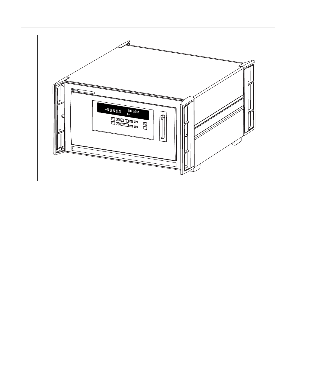
1-1. 2680A/2686A Instrument ................................................................................ 1-4
1-2. 2680A/2686A Front Panel............................................................................... 1-5
1-3. Typical Front Panel Display During Scanning and Monitoring...................... 1-6
1-4. 2680A/2686A Rear Panel ................................................................................ 1-7
1-5. DIO Connector Module ................................................................................... 1-13
2-1. Instrument Preparation..................................................................................... 2-4
2-2. Connecting the Instrument to a Power Source................................................. 2-6
2-3. Alarm/Trigger I/O Connector.......................................................................... 2-9
2-4. External Trigger Wiring for a Group of Instruments....................................... 2-11
2-5. Universal Input Module Connections .............................................................. 2-13
2-6. 2-Wire and 4-Wire Connections..................................................................... 2-14
2-7. Digital I/O Connector ...................................................................................... 2-16
2-8. Front Panel Controls ........................................................................................ 2-17
2-9. Front Panel Indicators...................................................................................... 2-19
2-10. Rear Panel Controls ......................................................................................... 2-22
2-11. Displaying a Monitor Channel......................................................................... 2-26
2-12. Examples During Monitor ............................................................................... 2-26
2-13. Examples for Digital I/O, Relay, and Totalizer Status .................................... 2-29
2-13. Reviewing and Setting the Base Channel Number.......................................... 2-32
2-14. Examples for Reviewing and Setting the BCN................................................ 2-32
2-14. Reviewing and Setting the Line Frequency..................................................... 2-34
2-15. Examples for Reviewing and Setting the Line Frequency............................... 2-34
2-15. Reviewing and Setting the Isolated Network Type to Isolated........................ 2-36
2-16. Examples for Reviewing and Setting the Network Type................................. 2-36
2-17. Examples for Reviewing and Setting General Network Parameters ............... 2-38
2-17. Viewing the Instrument Ethernet Address....................................................... 2-45
2-18. Examples for Viewing the Ethernet Address................................................... 2-45
2-19. Preparing for Network Operation .................................................................... 2-48
2-20. Host Computer/Instrument Direct Connection ................................................ 2-49
2-21. Interconnection Using 10/100BaseT (Twisted Pair) Wiring ........................... 2-51
4-1. Replacing the Fuse........................................................................................... 4-8
ix
Page 18

2680A/2686A
Users Manual
4-2. Performance Test Setup .................................................................................. 4-11
4-3. 2-Wire Connections to 5700A......................................................................... 4-24
4-4. 4-Wire Connections to the Universal Input Module (Resistor)....................... 4-25
4-5. 4-Wire Connections to the Universal Input Module (5700A)......................... 4-26
A-1. 2680 Series Chassis......................................................................................... A-30
C-1. Comparison of Common Waveforms.............................................................. C-3
D-1. 385 RTD.......................................................................................................... D-2
D-2. 375 RTD.......................................................................................................... D-3
D-3. 391 RTD.......................................................................................................... D-4
D-4. 392 RTD.......................................................................................................... D-6
G-1. 10/100BaseT Ethernet Cables ......................................................................... G-2
x
Page 19

Chapter 1
Overview
Introduction 1-3
Contacting Fluke ............................................................................................. 1-3
Instrument Features and Capabilities .............................................................. 1-5
Mainframe Features.................................................................................. 1-8
Trigger Input......................................................................................... 1-8
Trigger Output...................................................................................... 1-8
PC Card ATA Interface (2686A Only)................................................. 1-8
Master Alarm........................................................................................ 1-9
Interval Trigger..................................................................................... 1-9
External Trigger.................................................................................... 1-9
Alarms .................................................................................................. 1-9
Channel Monitoring.............................................................................. 1-10
Alarm Trigger....................................................................................... 1-10
Channel Numbering.................................................................................. 1-10
Computed Channels.................................................................................. 1-11
Mx+B Scaling........................................................................................... 1-11
Analog Channels....................................................................................... 1-11
Digital I/O Module Option........................................................................ 1-12
Digital I/O............................................................................................. 1-12
Relay Output......................................................................................... 1-12
Totalizer................................................................................................ 1-12
User Interface .................................................................................................. 1-13
Operating a 2680 Series Data Acquisition System.......................................... 1-14
Isolated Networks ..................................................................................... 1-14
General Networks ..................................................................................... 1-14
Ethernet Port ............................................................................................. 1-14
Group Operations...................................................................................... 1-15
Scanning and Logging .............................................................................. 1-15
RS-232 Interface....................................................................................... 1-17
Host Computer Requirements ......................................................................... 1-17
Options and Accessories ................................................................................. 1-18
Contents Page
1-1
Page 20

2680A/2686A
Users Manual
1-2
Page 21

Introduction
The 2680A Data Acquisition System (DAS) and 2686A Data Logging System
(DLS) provide 20 to 120 channels that operate in conjunction with Fluke DAQ
software for Windows to form a data acquisition system.
The 2686A comes with a removable PC Card (PCMCIA) for stand-alone storage
operation. This socket accepts ATA memory cards up to 2 GB in size.
Each 2680 Series instrument can hold from 1 to 6 modules. These modules are the
Precision Analog module (PAI), Fast Analog module (FAI), and the Digital
IO/Relay and Totalizer module (DIO). These modules are all isolated from one
another. You can add the DIO module to the instrument in slot 6 only.
The analog modules measure dc volts, ac volts, ohms, temperature, frequency, and
dc current. Temperature measurements use thermocouples, thermistors or
resistance temperature detectors (RTDs). The instruments also have extensive
computed math capability. Besides using data collected from the analog modules
and digital totalizer, time can also be used in computed channel calculations.
The system scans 20 to 120 analog channels and calculates the values for up to 60
computed channels. Interval timers, alarm conditions, and/or an external signal
input can trigger scans. The Fluke DAQ software configures and controls up to 99
2680 Series instruments via an Ethernet connection. The software provides the
means to view scan data and log it into files. In addition, Fluke DAQ software
permits multiple master/slave groups to run simultaneously.
Overview
Introduction
1
The two analog modules that may be used with the 2680 Series are the FAI
module and the PAI module. The PAI modules emphasize precision with 5 ½
digits of resolution, .02% accuracy, and can withstand up to 150 V common mode
voltage (300 V on channels 1 and 11). The FAI modules emphasize increased
measurement speed with 4 ½ digits of resolution, 0.04% accuracy, and can
withstand up to 50 V common mode voltage. See Appendix A for instrument
specifications.
Contacting Fluke
To contact Fluke, call one of the following telephone numbers:
USA: 1-888-99-FLUKE (1-888-993-5853)
Canada: 1-800-36-FLUKE (1-800-363-5853)
Europe: +31 402-675-200
Japan: +81-3-3434-0181
Singapore: +65-738-5655
Anywhere in the world: +1-425-446-5500
Or, visit Fluke's Web site at www.fluke.com
1-3
.
Page 22
2680A/2686A
Users Manual
2680 SERIES DAQ SYSTEM
REVIEW
MAX
REM
LAST
SCAN
MIN
AUTO
SET
FUNC
MON
Mx+B
F
ALARM
C F RO
mV AC DC
LIMIT
x1Mk
HI
Hz
OFF
PRN
12
CH
LO
CAL
EXT
TR
Figure 1-1. 2680A/2686A Instrument
alg46f.eps
1-4
Page 23
Instrument Features and Capabilities
Instrument Features and Ca pabilities
The following describes the front and rear panels of the instrument and its
capabilities (Figures 1-2 to 1-4).
Overview
1
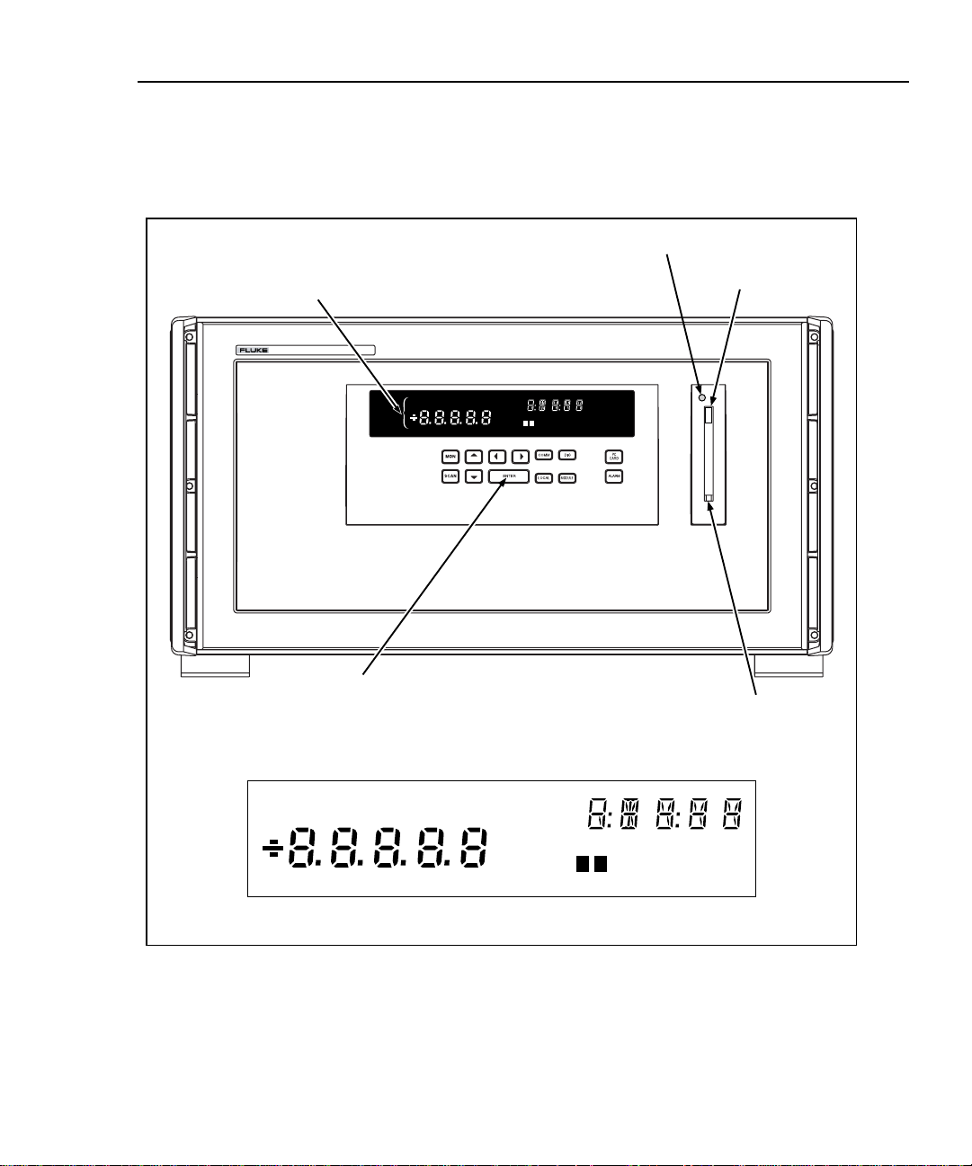
Primary, Secondary, and Annunciator Displays.
Indicators and annunciators for operating mode,
configuration, display, and data measurements.
2686A DATA ACQUISITION SYSTEM
F
FUNC
SET
MAX
REM
SCAN
REVIEW
MIN
LAST
Function Keys. User keys for configuring
ALARM
Mx+B
AUTO
MON
C F RO
mV AC DC
LIMIT
Hz
x1Mk
12
operating parameters such as Base Channel
Number, and front panel displays such as
channel monitoring, digital I/O status, and
totalizer count.
Status Indicator (LED)
PRN
OFF
HI
EXTCHTR
CAL
LO
Eject Button
PC Card Slot
(Only available
on the 2686A)
Hz
F
LIMIT
12
HI
LO
OFF
CAL
PRN
EXTCHTR
REVIEW
LAST
MAX
MIN
REM
AUTO
SCAN
MON
SET
Mx+B
FUNC
ALARM
C F RO
mV AC DC
x1Mk
Display detail
alg47f.eps
Figure 1-2. 2680A/2686A Front Panel
1-5
Page 24
2680A/2686A
Users Manual
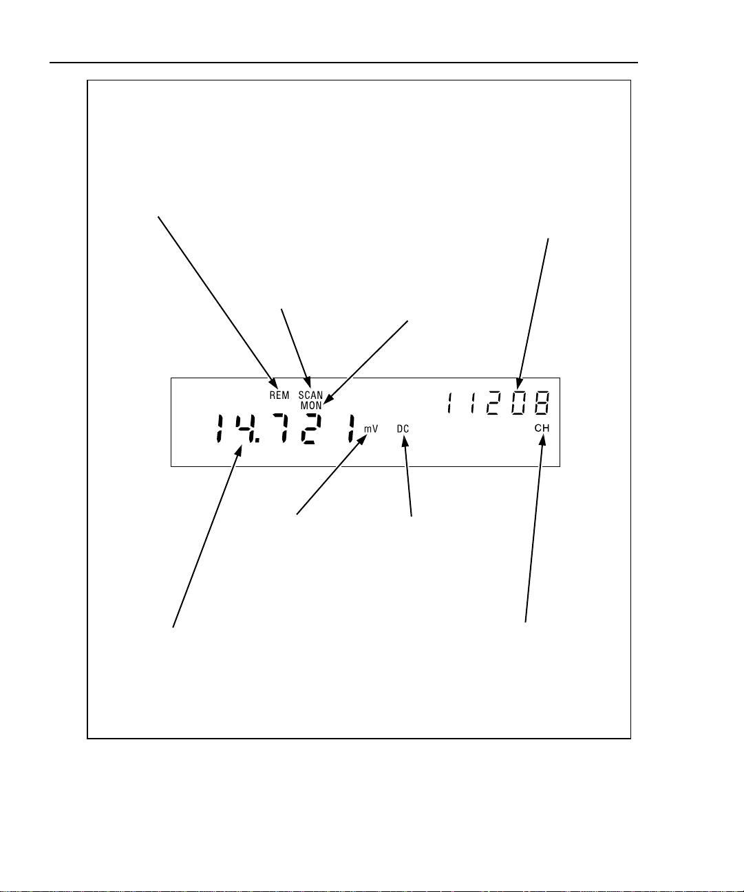
REM (Remote)
Annunciator.
Indicates the Host
Computer and the
Instrument are
communicating on the
network, i.e., the
instrument is being
operated remotely.
SCAN (Scanning)
Annunciator.
Indicates the
instrument is
scanning.
MON (Monitor)
Annunciator.
Indicates the
instrument is
monitoring a channel
(in this example,
analog channel 208).
You can monitor a
channel with or
without instrument
scanning.
11208 (Global
ChannelNumber).
Indicates the channel
being monitored is
11208. This number
consists of the
instrument Base
Channel Number (11),
Module Number (2)
and the selected
channel (08).
1-6
m Annunciator.
Indicates the multiplier
for the reading is .001
(milli). The other
multipliers are k (kilo,
1000), and M (mega,
1,000,000).
14.721 (Reading).
Indicates the reading
of the channel being
monitored has a value
of 14.721.
V DC (Volts DC)
Annunciator.
Indicates that the
number shown in the
primary display
(14.721) is the
function volts dc.
Figure 1-3. Typical Front Panel Display During Scanning and Monitoring
CH (Channel)
Annunciator.
Indicates the number
shown in the
secondary display
(11208) is the Global
Channel Number.
alg48f.eps
Page 25
Instrument Features and Capabilities
Overview
1
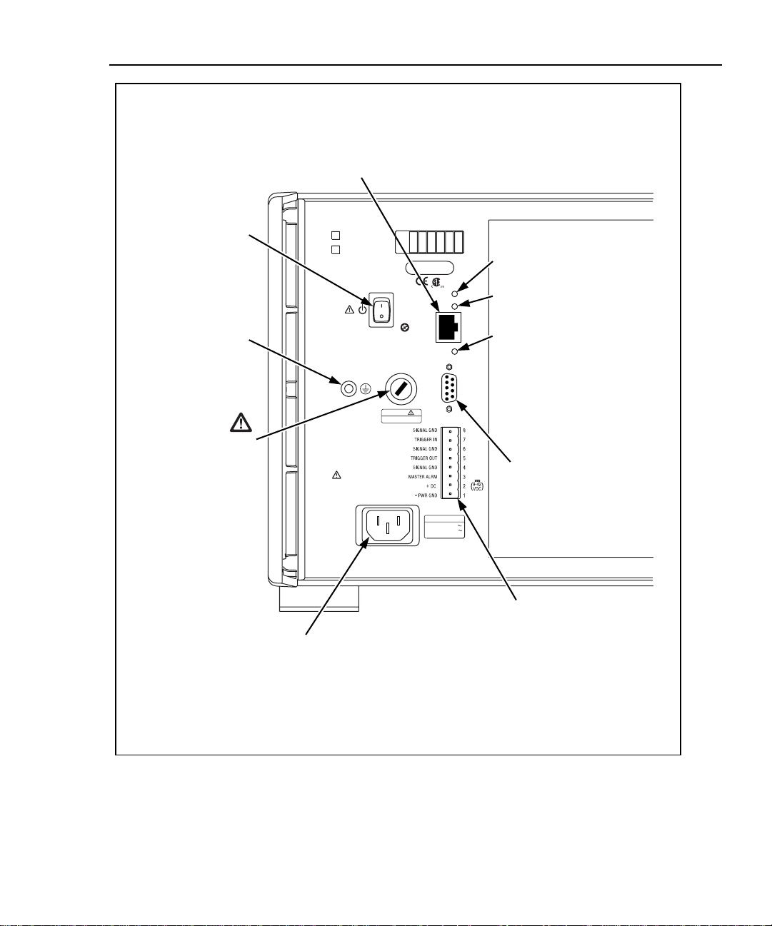
Ethernet 10/100BaseT Connector.
A RJ-45 connector that interfaces the
instrument with a 10/100BaseT
Twisted Pair Ethernet network. The
instrument automatically detects 10 or
100BaseT operation.
Power Switch.
Supplies power to the
instrument (ac or dc
operation).
Ground Terminal.
Connect to earth
ground when using
DC power.
Fuse Compartment
MODEL
2680A
2686A
FLUKE CORPORATION
MADE IN USA
www.fluke.com
PATENTS PENDING
STANDBY
CAUTION:
FOR FIRE PROTECTION
REPLACE ONLY WITH
A 250V FUSE OF
INDICATED RATING
CHASSIS
GROUND
FUSE
T1/2A 250V
WARNING:
TO AVOID
ELECTRIC SHOCK GROUNDING
CONNECTOR IN POWER CORD
MUST BE CONNECTED
NO INTERNAL USER SERVICEABLE PARTS.
REFER SERVICE TO QUALIFIED SERVICE PERSONNEL
AC Power Connector.
Connects to any line source
of 100 to 240 V ac (50/60 Hz).
SLOT CONFIGURATION
1
2
3456
SERIAL NUMBER
XMT
RCV
10/100 BASE T
ETHERNET
NOT FOR
CONNECTION
TO PUBLIC
TELEPHONE
SYSTEM
LINK
RS-232
SERIAL
PORT
(SB)
MAIN SUPPLY
100V- 240V
47Hz / 63Hz
100VA MAX
Ethernet Indicators.
XMT (transmit) blinks red for
instrument Ethernet transmissions.
RCV (receive) blinks red for any
Ethernet activity on the network.
LNK (link) lights red if 10BaseT is
operating, green if 100BaseT is
operating.
RS232
Serial Port
(for service use)
ALARM/TRIGGER I/O Connector.
Master Alarm output is logic low
when any channel is in alarm;
Trigger Out output is logic low for
nominal 125 ms start of any scan;
Trigger In input logic low triggers
scanning; DC PWR (dc volts input)
input is 9 to 45 V dc to power the
instrument.
alg60f.eps
Figure 1-4. 2680A/2686A Rear Panel
1-7
Page 26

2680A/2686A
Users Manual
Mainframe Features
Trigger Input
Trigger Input is an instrument connection used to trigger scans from an external
source. The connection uses the rear panel Trigger In and GND (Figure 1-4). A
logic low or contact closure between Trigger In and GND triggers an instrument
scan if External Trigger is enabled. While the trigger input line is held low, the
instrument continues to scan at Interval 2.
When there is no trigger input, an internal pull-up resistor holds the input at logic
high (nominal +5.0 V dc).
Trigger Output
Trigger Output is an output line that, when enabled, goes to logic low for 125 µs
every time a scan begins. The connection uses the rear panel Trigger Out and GND
(Figure 1-4). Use the Trigger Output to trigger other instruments by their Trigger
Input connection and to interface with external equipment. An internal pull-up
resistor holds the trigger output line at a logic high (nominal +5.0 V dc) when
there is no trigger output.
PC Card ATA Interface (2686A Only)
A PC ATA card interface provided in each 2686A system. It can be used to store
data when there is no network connection. The data produced is DOS compatible.
When scanned data is first recorded on the card, a copy of the configuration of the
instrument is also recorded. As a result, you can stop scanning, remove the card,
read results, reinstall the card in the same instrument, and restart scanning and
have only one file created. If you want to clear the existing memory card, the front
panel keys can be used to erase the card contents. You can use up to 2 GB ATA
compatible PC Card in a 2686A instrument. See Chapter 2 for additional
information.
1-8
An error will result if a card has partially been filled with data from a different
configuration. This can be fixed by using the front panel keys to erase the existing
data in the card.
XWCaution
Removing the PC card while the storage LED is on may
cause a loss of data. Before removing the card, stop the
instrument scanning. Loss of power while data is being
written to the card may also result in loss of data.
Page 27

Master Alarm
Master Alarm is an instrument output line that is logic low (nominal +0.8 V dc) for
as long as any channel is in alarm while scanning is active. The connection uses
the ALARM/TRIGGER I/O terminals Master Alarm and GND (Figure 1-4). This
TTL output interfaces with external equipment such as warning lights, alarms,
automatic shutdowns, and paging systems. When the alarm condition ends or
scanning stops, an internal pull-up resistor sets the output at logic high (nominal
+5.0 V dc).
Interval Trigger
Interval Trigger is an internal software timer you can set using Fluke DAQ
software. It permits scanning at regular time intervals using Interval 1. Interval 1 is
in seconds, with a minimum of 0.000 (continuous scanning) and a maximum of
86400.000 (one scan every 24 hours). The time resolution is to the millisecond, for
example, 12.345 seconds.
External Trigger
External Trigger is started by an external event and triggers scanning when an
external logic low is applied to the instrument Trigger In line. As long as the
Trigger Input remains low, scans are triggered at regular time intervals using
Interval 2. Interval 2 is in seconds, with a minimum of 0.000 (continuous
scanning) and a maximum of 86400.000 (one scan every 24 hours). The time
resolution is to the millisecond, for example, 12.345 seconds. When scanning
starts, if the External Trigger is logic low, scanning begins at the Interval 2 rate. If
the External Trigger is logic high, no scans are triggered until the trigger line is set
to logic low.
Overview
Instrument Features and Capabilities
1
If one or more external trigger events occur while a scan is in progress, one
triggered scan follows the scan in progress.
Alarms
Two alarms, Alarm 1 and Alarm 2, can be applied to any configured channel. An
alarm condition occurs when a measurement falls below a low alarm value, rises
above a high alarm value, or is between the two alarm values. If you apply Mx+B
scaling as part of the channel configuration, the instrument bases the alarms on the
scaled values.
When any configured channel is in alarm, the Alarm annunciator is on dim, or
bright if a channel in alarm is being used as an Alarm Trigger. When a channel is
in alarm, the rear-panel Master Alarm output is asserted (logic low). You can use
alarms to trigger scanning (see Alarm Trigger later in this chapter) and to set a
Digital I/O line to a logic low (see Digital I/O Module later in this chapter) or
close a relay. The Fluke DAQ software displays and records alarm conditions.
1-9
Page 28

2680A/2686A
Users Manual
Channel Monitoring
Channel monitoring takes place at the front panel of the instrument. Use the front
panel MON key and arrow keys to select a channel for monitoring. The Fluke
DAQ software also allows the selection of a channel to monitor during scanning.
For an example of a front panel display of the instrument during monitoring, see
Figure 1-3. Monitor can also automatically scroll up or down through the channels
displaying each channel and then moving to the next. The channel monitoring
display nominally updates once per second.
Alarm Trigger
The alarm trigger triggers scanning when a channel designated as an alarm trigger
goes into alarm. As long as any such channel is in alarm, scans are triggered at
regular time intervals using Interval 2. Interval 2 is in seconds, with a minimum of
0.000 (continuous scanning) and a maximum of 86400.000 (one scan every 24
hours). The time resolution is to the millisecond, for example, 12.345 seconds.
The instrument performs background monitoring of channels designated as alarm
triggers to check for alarm conditions using Interval 3.
You can combine Alarm Trigger with External Trigger and Interval Trigger. For
example, set the Interval Trigger for 60 seconds (Interval 1) and the Alarm Trigger
for 10 seconds (Interval 2). Scanning is at 60 second intervals except when a
channel designated as an alarm trigger is in alarm, when scanning is at 10 second
intervals.
Channel Numbering
Each instrument channel, measured or computed, is identified by the Global
Channel Number (GCN). The first two digits of the GCN are the Base Channel
Number (01 to 99) that identifies the instrument. The third digit indicates the slot
or module number. The last two digits are the channel number. For example, GCN
28318 indicates instrument 28 , slot 3, and channel 18. When the instrument is in
the quiescent state, the channel number of the GCN shows dashes, for example,
45--- for instrument 45.
1-10
alg49f.eps
Page 29

Computed Channels
In addition to the analog channels, the instrument provides an additional 60
computed channels by processing analog channels and other computed channels.
The computed channels are numbered 901 to 960. The following calculations are
used:
• The average of a group of channels,
• The difference between any two channels,
• The difference between a channel and the average of a group of channels,
• A mathematical equation. Other channels, time and totalizer can be part of the
equation.
For computed channels, the functions use 24 bits and an exponent for calculations.
As a result, when the totalizer or time exceed 16,777,215 units, the number will be
rounded off to remain within the 24 bits. For example, one count more than
16,777,215 would be rounded to 16,777,220 in a computed channel.
Mx+B Scaling
Mx+B scaling multiplies a measurement by a multiplier M and then offsets it by
an offset B. For example, Mx+B scaling of 100x+50 applied to a measured or
computed channel value of 1.15 results in a reading of 100(1.15)+50=165. A
common use of Mx+B scaling is to scale a sensor or transducer to provide for
display and recording in engineering units. The Mx+B annunciator lights when a
monitored channel has scaling applied.
Overview
Instrument Features and Capabilities
1
Analog Channels
The analog channel measurement connections are made via the Universal Input
Modules. External signal conditioning for the analog inputs is not necessary for
most common electrical signals. The input channels are numbered 101 to 120, 201
to 220, 301 to 320, 401 to 420, 501 to 520, and 601 to 620. The host computer
configures all analog channels using the Fluke DAQ software.
There are two different analog modules available for the 2680 Series instruments
with up to 6 modules for any given instrument. Each module is isolated from every
other module to 300 V. One analog module is the fast analog module (FAI) and
has a maximum rate of 667 channel readings per second but a limited input voltage
of 50 V dc or 30 V rms. The other analog module is the precision analog module
(PAI). The PAI has a maximum of 300 V dc rms (on channel 1 and 11) and a
maximum rate of 133 channel readings per second. All other channels are 150 V
maximum for the PAI module. The Digital IO/Relay and Totalizer module can
monitor digital type (High or Low) signals.
1-11
Page 30

2680A/2686A
Users Manual
Digital I/O Module Option
Digital I/O
20 general-purpose open collector digital outputs and Transistor Logic (TTL)
digital input lines are available in the Digital I/O module. A logic low can be
applied to an I/O line as an input; alternatively a logic low can be internally set by
the instrument if the channel is set as an output. If no logic low is set or applied
externally, the input is pulled up to logic high (+5 V) internally. An output logic
low condition takes precedence over an input logic high condition. When the I/O
lines are used as inputs, they signal an external condition that can be correlated to
the data measurements.
Fluke DAQ software records the status of the Digital I/O as the decimal equivalent
of the 20 binary bits. For example, 1111 1111 1111 1111 1111 (DIO19 to DIO0) is
represented by decimal 1,048,575; 0000 0000 0000 0000 1111 is represented by
decimal 15.
The instrument can display the Digital I/O status in binary format at the front panel
with updates each second.
Relay Output
There are also 8 relays capable of switching up to 1 A or 250 V rms. Fluke DAQ
software records the relay status as bits 24-31 of the DIO value. The selay status
can also be displayed on the instrument front panel.
1-12
Totalizer
The Digital I/O module also includes a totalizer with external enable. The totalizer
input counts contact closures or voltage transitions with a maximum count of
4,294,967,295. There is also an external totalizer enable that can be used to enable
the totalizer. The totalizer can be preset and count down to zero or count up from
zero.
The connections for the totalizer are the Σ and Σen input lines on the Digital I/O
connector (Figure 1-5). The instrument continuously detects the totalizer input on
the rear panel independently from instrument scanning and other activities. If the
Totalizer overflows (reaching the maximum count), the display briefly shows OL
(overload) and begins counting again.
Page 31

Overview
User Interface
1
A totalizer input from contact closures increments on the “open” portion of the
switch sequence close-open. To prevent switch contact “bounce” from triggering
false readings, select the Totalizer Debounce feature. A totalizer input from
voltage transitions increments during low-to-high voltage transitions with a
nominal threshold of +1.4 V. The maximum voltage input is +30 V dc, and the
minimum voltage input is -4.0 V dc. The maximum totalizer rate is 5,000
transitions per second without debounce and 500 transitions per second with
debounce.
The instrument reports totalizer status with scan data and can display it at the front
panel. You can initialize the totalizer count by cycling power to the instrument or
using Fluke DAQ software.
User Interface
Fluke DAQ is the operating software for the 2680 Series instruments. It lets you
configure and operate your system through a Windows-based environment. You
can install Fluke DAQ on either Windows XP, 2000 (Service Pack 3 required), or
NT (Service Pack 6.0 required). Chapter 3 of this manual provides detailed
information about using Fluke DAQ software.
K3A K3B
K6A K6B
RELAY
DIAGRAM
RELAYS DIGITAL I/O
K2A K2B K1A K1B
K5A K5B K4A K4B
K8BBK7A K7B
K8A
0
8
16
A
Kn
Figure 1-5. DIO Connector Module
DIO 0-7
DIO 8-15
DIO 16-19
-4V +30V
7
15
19
MAX
en
alg57f.eps
You can use Fluke DAQ software to easily perform the following:
• Configure your 2680 Series network and instrument settings.
• Download/upload configuration to the instruments.
• Send commands to the digital I/O.
1-13
Page 32

2680A/2686A
Users Manual
• Monitor the instruments on-line values and alarms.
• Plot trend charts, retrieve historical trends, acknowledge alarms, and export
data files in .csv format.
Note
Fluke DAQ supports the NetDAQ 2680 models (2640A and 2645A)
as well as the 2680A and 2686A.
Operating a 2680 Series Data Acquisition Sy stem
You can configure 2680 Series instruments to operate over either an isolated or
general network. An isolated network includes 2680 Series instruments and a host
computer only. A general network may also include servers, routers, gateways, or
other network devices. Both types of networks interconnect using Ethernet (i.e.,
using the IEEE 802.3 or ISO 8802-3 standards).
A unique 2 digit Base Channel Number (BCN) entered at the instrument front
panel identifies each 2680 Series instrument on the network. All subsequent
operations refer to the instrument by BCN. Fluke DAQ supports up to 99
instruments for operation. You cannot operate an instrument from more than one
host computer at a time.
Isolated Networks
An isolated network consists of only 2680 Series instruments and host computer.
The advantages include simplified setup, faster network operation, and freedom
from general network problems. Data throughput specifications are guaranteed
only for isolated networks. When you set Fluke DAQ software for an isolated
network, it automatically handles instrument IP addressing. You must configure
your host computer networking software to use a host computer IP address of
198.178.246.101 and subnet mask of 255.255.255.0. See Setting Host Computer
Network Parameters in Chapter 2 of this manual.
General Networks
A general network consists of host computers, 2680 Series instruments, and
servers, routers, gateways, or other network devices. Refer connectivity issues to
your network administrator and review Network Considerations in Appendix H for
more information. When you install the software for a general network, you must
enter the instrument IP addresses manually. For more information, see Reviewing
and Setting the Network Type in Chapter 2.
Ethernet Port
Each 2680 Series instrument has a 10/100BaseT twisted pair Ethernet network
port. The instrument automatically monitors the Ethernet port.
1-14
Page 33

Group Operations
Using Fluke DAQ, you can group scan data from multiple instrument modules and
sources. Fluke DAQ can record data from all sources in the group into a single .csv
data file.
When grouping data, one module or instrument is designated as the Master. The
Master determines the times of the scans in the .csv data file. Scan data can be
grouped while scanning, or after scanning has ended using the Export feature.
Scanning and Logging
When a scan is triggered, the instrument scans the 20-120 analog channels, scans
the Digital I/O channels and totalizer and calculates the 60 computed channels. It
stores the resulting time-stamped data in a scan record. Scans can be triggered
from several sources:
• Interval Trigger, where an elapsed interval timer triggers a scan.
• External Trigger, where an external input (ground or logic low) applied to the
instrument, the Trigger In signal triggers a scan.
• Alarm Trigger, where a channel going into alarm starts a scan.
Fluke DAQ software obtains scan records from the instruments and logs the data
into a history database and optionally into a .csv file. Each scan record consists of
a timestamp, values from all configured and recording analog channels and
computed channels, and the alarm states, plus the Digital I/O line status and the
count of the totalizer if the Digital I/O Relay module is in the instrument.
Overview
Operating a 2680 Series Data Acquisition System
1
A number of factors can affect the actual scan rate in the 2680A/2686A
instruments. These include:
• The number of active modules
• The number of active channels
• Use of the DIO for alarms or as a totalizer/counter
• Writing to a PC card
• Network data rates.
There is a 2.6 ms overhead associated with accessing each module in a instrument.
There is overhead associated with reading each channel. For an FAI module, it is
about 1.4 ms per channel. Consequently, including the module overhead, when
reading one FAI with 20 active channels, you can get the scanned data in 30 ms or
667 channels per second. If you read only one channel, it takes 4 ms for a rate of
only 250 channels per second. For high-speed measurements, it is faster to use
fewer channels on each module. However, when a single channel and minimum
scan interval are used on four or more FAIs, the internal program may not keep up
with the scan data rate and some data could be lost.
1-15
Page 34

2680A/2686A
Users Manual
The internal evaluation algorithm allows data from slower modules to be recorded
regardless of the scan speed of other modules. The measurements made by slower
PAIs well still be recorded even when running in a chassis of FAIs. Only the
fastest modules may experience some loss of data. If the user sets the interval time
of each module to 31 ms or greater, no data will be lost for any number of FAI
channels. In addition, if the total number of scans for all of the modules combined
is less than 1000 scans per second, there should be no problem with losing scans.
Below is a table showing the timing.
Using the DIO for alarms or the totalizer will slow system throughput because of
its 4 ms overhead. DIO data is provided with each module scan. Consequently,
having five modules scanning at the same speed will incur an additional 20 ms
delay if a DIO is active.
Writing to the PC card is more time consuming than writing to internal memory.
This is partly because the 2686A instrument uses a DOS compatible file storage
system that requires additional overhead. As a result, the maximum scan time
while storing data will be slowed.
Table 1-1. Channel Count vs Scan Rate
2680A/2686A Channel Rate With No Lost Data*
Channel Count Module Count Typical Total Time (ms) Typical Scan Rate (ch/s)
1 1 4 250
1 2 4 500
1 3 4 750
1 4 4 1,000
1 5 5 1,000
1 6 6 1,000
20 1 30 666
40 2 30.1 1,329
60 3 30.1 1,993
80 4 30.1 2,658
100 5 30.1 3,322
120 6 30.1 3,990
* Assumes no DIO, no PC card storage, no network communication, and only FAI modules in the
chassis.
1-16
Page 35

Network traffic can have a significant impact on instrument throughput. More
importantly, if the 2680 Series instruments cannot output the readings quickly
enough, the internal memory will eventually over flow. Depending on the setting
the user chose, the readings will either be written to the last location in memory or
start to write over the oldest data location (the default). In either case, data can be
lost.
The internal buffer memory can store up 30,000 scans. A scan can contain up to 20
channels from one module plus up to 60 computed channels. At the fastest
measurement rates, 6 FAI modules could fill up the internal memory in about 150
seconds. Once the internal memory is full, data will be lost.
RS-232 Interface
The instruments include an RS-232 port for calibration, servicing, and factory
procedures; the RS-232 port is not used for instrument control or scan data
collection. See Calibration in Chapter 4 of this manual.
Host Computer Requirements
The host computer used for instrument operations must meet the following
minimum requirements:
Overview
Host Computer Requirements
1
• PC with a 200 MHz microprocessor or greater, running Windows XP, 2000
(Service Pack 3 required), or NT (Service Pack 6.0 required)
• Color VGA Monitor
• 200 MB of free disk space
• CD ROM drive
1-17
Page 36

2680A/2686A
Users Manual
Options and Accessories
Table 1-2 summarizes the available models, options and accessories.
Table 1-2. Models, Options and Accessories
Model Description
2680A-FAI Fast Analog Input Module
2680A-PAI Precision Analog Input Module
2680A-DIO Digital I/O Relay with Totalizer Module
2680A-102 Extra Digital Connector Module
2680A-180 Extra Input Module for analog input procedures
2680A-800 16 MB Memory Card
2680A-801 128 MB Memory Card
2680A-802 256 MB Memory Card
2680A-805 512 MB Memory Card
2680A-810 1 GB Memory Card
1-18
2680A-BLANK Blank Module
2680A-APSW Fluke DAQ Software. Included with the purchase of each chassis.
2680A-DEVSW Fluke Development Software
2680A-DLL Fluke DLL Library routines for the development of custom user software.
2680A-OPC Fluke OPC Software. Used to configure a PC to act as an OPC server
and provide virtual contact with a 2680 Series instrument.
Page 37

Chapter 2
Preparing for Operation
Introduction 2-3
Instrument Preparation..................................................................................... 2-4
Unpacking and Inspecting the Instrument................................................. 2-5
Positioning and Rack Mounting................................................................ 2-5
Connecting to a Power Source and Grounding ......................................... 2-5
Operating Using AC Power .................................................................. 2-6
Operating Using DC Power .................................................................. 2-7
Grounding and Common Mode Voltage............................................... 2-7
Alarm/Trigger I/O Connection.................................................................. 2-7
Trigger Input......................................................................................... 2-8
Trigger Output ...................................................................................... 2-9
Master Alarm ........................................................................................ 2-10
External Trigger Wiring for a Group ........................................................ 2-10
Universal Input Module Analog Connections (2620A-180) ..................... 2-12
Shielded Wiring .................................................................................... 2-15
Crosstalk Considerations ...................................................................... 2-15
Digital I/O Connector Module. ................................................................. 2-15
Digital I/O............................................................................................. 2-16
Totalizer................................................................................................ 2-16
Totalizer Enable.................................................................................... 2-17
Relays.................................................................................................... 2-17
Controls and Indicators ............................................................................. 2-17
Front Panel Controls ............................................................................. 2-17
Front Panel Indicators........................................................................... 2-19
Rear Panel Controls .............................................................................. 2-22
Rear Panel Indicators............................................................................ 2-23
Front Panel Operating Procedures............................................................. 2-24
Power-On Options ................................................................................ 2-24
Displaying a Monitor Channel.............................................................. 2-25
Displaying the Digital I/O Status.......................................................... 2-27
Displaying Relay Status........................................................................ 2-28
Displaying the Totalizer Status............................................................. 2-30
Contents Page
2-1
Page 38

2680A/2686A
Users Manual
Reviewing and Setting the Base Channel Number............................... 2-31
Reviewing and Setting the Line Frequency.......................................... 2-33
Reviewing and Setting the Network Type............................................ 2-35
Reviewing and Setting the General Network Socket Port.................... 2-40
Reviewing and Setting the General Network IP Address..................... 2-41
Reviewing and Setting the Subnet Mask and Default Gateway........... 2-42
Viewing the Instrument Ethernet Address ........................................... 2-44
Reviewing and Setting PC Card Options ............................................. 2-46
Host Computer and Network Preparation ....................................................... 2-47
Installing Host Computer Ethernet Adapter ............................................. 2-47
Instrument and Host Computer Interconnection....................................... 2-49
Host Computer/Instrument Direct Connection..................................... 2-49
Interconnection Using 10/100BaseT (Twisted Pair) Ethernet Wiring . 2-50
Set Up Windows Networking................................................................... 2-52
Setting Host Computer Networking Parameters....................................... 2-53
Installing Fluke DAQ Software ................................................................ 2-53
Testing and Troubleshooting........................................................................... 2-54
Installing and Testing the Installation....................................................... 2-54
Troubleshooting Network Problems......................................................... 2-58
2-2
Page 39

Introduction
This chapter describes how to prepare the instrument, host computers and network
for operation, and how to test and troubleshoot system operation.
Setting up your system requires the following steps (described in detail later in this
chapter), performed in the order shown:
• Instrument Preparation Unpacking and setting up the 2680 Series
instruments. This section of the manual describes all the connections, controls,
and indicators on the instrument.
• Host Computer Ethernet Adapter Installation Installing an Ethernet
adapter such as the 3COM Fast Etherlink 10/100 BaseTx interface card if your
host computer does not already have one.
• Instrument and Host Computer Interconnection Connecting the host
computer(s) and instruments.
• Host Computer Software Installation Installing Fluke DAQ software and
networking software.
• Testing and Troubleshooting Testing and verifying network operation, and
troubleshooting any difficulties.
Preparing for Operation
Introduction
2
2-3
Page 40

2680A/2686A
Users Manual
Instrument Preparation
This section contains information for preparing the instrument for operation
summarized in Figure 2-1.
1
3
DC
AC
5
Master Alarm
and
Trigger Connections
Unpacking and
Inspection
SLOT CONFIGURATIONMODEL
- 2680A
1
2
3456
- 2686A
FLUKE CORPORATION
MADE IN USA • www.fluke.com
PATENTS PENDING
XMT
RCV
ETHERNET
NOT FOR
CONNECTION
TO PUBLIC
TELEPHONE
SYSTEM
LNK
CHASSIS
GROUND
RS-232
SERIAL
PORT
FUSE
MAINS SUPPLY
(SB)
/240V 100V
T1/2A 250V
SIGNAL GND
CAUTION:
8
FOR FIRE PROTECTION
TRIGGER IN
REPLACE ONLY WITH
7
A 250V FUSE OF
SIGNAL GND
INDICATED RATING
6
TRIGGER OUT
5
SIGNAL GND
4
MASTER ALRM
3
WARNING:
TO AVOID
(
)
+
DC PWR
9-42VDC
2
ELECTRIC SHOCK GROUNDING
CONNECTOR IN POWER CORD
-
PWR GND
1
MUST BE CONNECTED
47Hz /63Hz
100VA MAX
NO INTERNAL USER SERVICEABLE PARTS.
REFER SERVICE TO QUALIFIED SERVICE PERSONNEL
Connecting to
a Power Source
SLOT CONFIGURATIONMODEL
- 2680A
1
2
3456
- 2686A
FLUKE CORPORATION
MADE IN USA • www.fluke.com
PATENTS PENDING
XMT
RCV
ETHERNET
NOT FOR
CONNECTION
TO PUBLIC
TELEPHONE
SYSTEM
LNK
CHASSIS
GROUND
RS-232
SERIAL
PORT
FUSE
MAINS SUPPLY
(SB)
/240V 100V
T1/2A 250V
SIGNAL GND
CAUTION:
8
FOR FIRE PROTECTION
TRIGGER IN
REPLACE ONLY WITH
7
A 250V FUSE OF
SIGNAL GND
INDICATED RATING
6
TRIGGER OUT
5
SIGNAL GND
4
MASTER ALRM
3
WARNING:
TO AVOID
(
)
+
DC PWR
9-42VDC
2
ELECTRIC SHOCK GROUNDING
CONNECTOR IN POWER CORD
-
PWR GND
1
MUST BE CONNECTED
47Hz /63Hz
100VA MAX
NO INTERNAL USER SERVICEABLE PARTS.
REFER SERVICE TO QUALIFIED SERVICE PERSONNEL
2
4
6
Positioning and
Rack Mounting
SLOT CONFIGURATIONMODEL
- 2680A
1
2
3456
- 2686A
FLUKE CORPORATION
MADE IN USA • www.fluke.com
PATENTS PENDING
XMT
RCV
ETHERNET
NOT FOR
CONNECTION
TO PUBLIC
TELEPHONE
SYSTEM
LNK
CHASSIS
GROUND
RS-232
SERIAL
PORT
FUSE
MAINS SUPPLY
(SB)
/240V 100V
T1/2A 250V
SIGNAL GND
CAUTION:
8
FOR FIRE PROTECTION
TRIGGER IN
REPLACE ONLY WITH
7
A 250V FUSE OF
SIGNAL GND
INDICATED RATING
6
TRIGGER OUT
5
SIGNAL GND
4
MASTER ALRM
3
WARNING:
TO AVOID
+
(
)
DC PWR
9-42VDC
2
ELECTRIC SHOCK GROUNDING
CONNECTOR IN POWER CORD
-
PWR GND
1
MUST BE CONNECTED
47Hz /63Hz
100VA MAX
NO INTERNAL USER SERVICEABLE PARTS.
REFER SERVICE TO QUALIFIED SERVICE PERSONNEL
Universal Input
Module Connection
SLOT CONFIGURATIONMODEL
- 2680A
1
2
3456
- 2686A
FLUKE CORPORATION
MADE IN USA • www.fluke.com
PATENTS PENDING
XMT
RCV
ETHERNET
NOT FOR
CONNECTION
TO PUBLIC
TELEPHONE
SYSTEM
LNK
CHASSIS
GROUND
RS-232
SERIAL
PORT
FUSE
MAINS SUPPLY
(SB)
/240V 100V
T1/2A 250V
SIGNAL GND
CAUTION:
8
FOR FIRE PROTECTION
TRIGGER IN
REPLACE ONLY WITH
7
A 250V FUSE OF
SIGNAL GND
INDICATED RATING
6
TRIGGER OUT
5
SIGNAL GND
4
MASTER ALRM
3
WARNING:
TO AVOID
+
(
)
DC PWR
9-42VDC
2
ELECTRIC SHOCK GROUNDING
CONNECTOR IN POWER CORD
-
PWR GND
1
MUST BE CONNECTED
47Hz /63Hz
100VA MAX
NO INTERNAL USER SERVICEABLE PARTS.
REFER SERVICE TO QUALIFIED SERVICE PERSONNEL
External Trigger
(Group Instrument)
2-4
MAX
REVIEW
MIN
LAST
7
SET
REM
SCAN
ALARM
Mx+B
AUTO
MON
°C °F RO
mV AC DC
Hz
x1Mk
Ω
Control and Indicators
LIMIT
12
PRN
OFF
HI
EXTCHTR
CAL
LO
8
Front Panel
F
FUNC
Procedures
alg05f.eps
Figure 2-1. Instrument Preparation
Page 41

Unpacking and Inspecting the Instrument
Verify the contents of the shipping package against the shipping label located on
the outside of the shipping package. If any items are missing or damaged, report
the problem immediately to your Fluke representative.
Carefully remove the instrument from its shipping container, saving the packaging
materials if possible.
Positioning and Rack Mounting
Position the instrument in any location that meets the environmental specifications.
(Refer to Appendix A.) The Rack Mounting Kit for the 2680 Series, model Y2680,
(Part Number 1777577) includes hardware and instructions for mounting the
instrument.
Connecting to a Power Source and Grounding
You can connect the instrument to an ac power source between 100 – 240 V ac
(50/60 Hz), to a dc power source between 9 and 45 V dc, or to both. Fluke
guarantees equipment specifications only for 50 Hz and 60 Hz mains operation
and dc operation. Refer to Figure 2-2 and the descriptions below for making power
connections. If you connect both ac power and dc power to the instrument, the
instrument uses ac power when it exceeds approximately 8 times the value of the
dc voltage. Automatic switchover occurs between ac and dc power without
interrupting instrument operation.
If you connect both ac and dc power to the instrument, the ac and dc ground
connections must be to the same earth ground terminal.
Preparing for Operation
Instrument Preparation
2
2-5
Page 42

2680A/2686A
Users Manual
Ground for
DC power
operation.
Warning
If voltages greater than
50 V are to be measured,
a separate earth ground
must be attached to this
rear panel ground
connector when the
instrument is operated
from battery power.
MODEL
2680A
2686A
FLUKE CORPORATION
MADE IN USA
www.fluke.com
PATENTS PENDING
STANDBY
CHASSIS
GROUND
WARNING:
ELECTRIC SHOCK GROUNDING
CONNECTOR IN POWER CORD
MUST BE CONNECTED
NO INTERNAL USER SERVICEABLE PARTS.
REFER SERVICE TO QUALIFIED SERVICE PERSONNEL
SLOT CONFIGURATION
CAUTION:
FOR FIRE PROTECTION
REPLACE ONLY WITH
A 250V FUSE OF
INDICATED RATING
FUSE
T1/2A 250V
TO AVOID
1
2
SERIAL NUMBER
10/100 BASE T
ETHERNET
NOT FOR
CONNECTION
TO PUBLIC
TELEPHONE
SYSTEM
RS-232
SERIAL
(SB)
3456
XMT
RCV
LINK
PORT
MAIN SUPPLY
100V- 240V
47Hz / 63Hz
100VA MAX
Fuse
Compartment
External Battery
+
(DC Operation)
–
Line Cord
(AC Operation)
Figure 2-2. Connecting the Instrument to a Power Source
To avoid shock hazard when powering the instrument with
ac power, connect the power cord to a receptacle with an
earth ground.
Operating Using AC Power
Plug the line cord into the connector on the rear of the instrument as shown in
Figure 2-2. The instrument operates on any line voltage between 100 – 240 V ac
without adjustment. Fluke warrants the instrument to meet specifications only at
mains frequency 50 Hz and 60 Hz. Power consumption is nominally 30 watts. Be
sure the line cord ground terminal connects to an earth ground.
2-6
XWWarning
alg52f.eps
Page 43

To avoid shock hazard when powering the instrument with
dc power, connect the instrument ground terminal to an
earth ground.
Operating Using DC Power
The instrument operates from any dc voltage between 9 and 45 V. Power
consumption is a nominal 30 watts. To connect the POWER/ALARM/TRIGGER
connector to the rear panel, complete the following procedure:
1. Remove the POWER/ALARM/TRIGGER connector from the packing
material or instrument rear panel.
2. Loosen the wire clamp screw for the associated terminal.
3. Feed the wire into the gap between the connector body and the wire clamp.
4. Tighten the wire clamp; do not over tighten and crush the wire.
5. Repeat steps 2 through 4 for each wire.
6. Insert the connector in the rear panel.
A 4 amp fuse is used to protect the dc input from over current. This
fuse is located inside the 2680 Series chassis on the main controller
board. The fuse should only be replaced by a Fluke qualified
technician with all power disconnected from the instrument.
XWWarning
Note
Preparing for Operation
Instrument Preparation
2
Grounding and Common Mode Voltage
Connect the instrument chassis to a good earth ground (Figure 2-2) to prevent a
common mode voltage from raising the chassis to a high potential. For example, if
you measure the voltage across a resistor in a 50 V dc circuit, the instrument reads
the resistor voltage and ignores the 50 V dc common mode voltage. Since the
impedance between the channel inputs and chassis ground is not infinite, a
common mode voltage gradually leaks to the chassis ground. A good earth ground
prevents the chassis from rising to the common-mode voltage (50 V dc in this
case).
Alarm/Trigger I/O Connection
XWCaution
To avoid damage to the instrument, do not apply any
voltages greater than 30 V maximum between the
ALARM/TRIGGER I/O connector terminals and signal
ground.
2-7
Page 44

2680A/2686A
Users Manual
Trigger Input
The ALARM/TRIGGER I/O connector (Figure 2-3) on the rear panel of the
instrument provides connections to Trigger In, Trigger Out, and Master Alarm I/O
lines along with common ground connections. (See the Trigger Input, Trigger
Output, and Master Alarm Output sections in Chapter 1 for additional
information.) The dc power connection is also on this connector.
Complete the following procedure to make a connection to the
ALARM/TRIGGER I/O connector:
1. Remove the ALARM/TRIGGER I/O connector from the rear panel.
2. Loosen the wire clamp screw for the associated terminal.
3. Feed the wire into the gap between the connector body and the wire clamp.
4. Tighten the wire clamp; do not over tighten and crush the wire.
5. Repeat steps 2 through 4 for each wire.
6. Insert the connector in the rear panel.
Trigger Input uses terminals Trigger In and GND. A contact closure or a TTL low
signal input between Trigger In and GND triggers instrument scanning when you
select External Trigger as a scan parameter. A TTL signal input triggers on the
falling edge of the signal. A contact closure input triggers on the "close" portion of
the switch sequence. Scanning continues at the Interval 2 rate while Trigger In is
held low. See Table A-3 in Appendix A for specifications.
2-8
Page 45

Preparing for Operation
Instrument Preparation
2
SIGNAL GND
TRIGGER IN
SIGNAL GND
TRIGGER OUT
SIGNAL GND
MASTER ALRM
+
DC PWR
- PWR GND
Instrument
8
7
6
5
4
3
9-42
2
)(
VDC
1
InstrumentFunction Connector
Signal Ground
Trigger In
Signal Ground
Trigger Out
Signal Ground
Master Alarm
DC Power
Power Ground
Figure 2-3. Alalrm/Trigger I/O Connector
8
7
6
5
4
3
2
1
Connector
alg53f.eps
Trigger Output
Trigger Output uses terminals Trigger Out and GND, and is a TTL signal that goes
to a logic low for 125 µs every time a scan begins. Use the Trigger Output to
trigger other instruments via their Trigger Input connection and to interface with
external equipment. You can enable or disable the Trigger Output using Fluke
DAQ software. The trigger output default is OFF. See Table A-4 in Appendix A
for complete specifications.
The Trigger Out signal can be used to synchronize a number of instruments in a
master/slave like setup. However, the maximum rate that a chassis can respond to
a trigger signal is 300 Hz. The master module should not be set to scan more often
than 300 times a second. The modules in the same chassis as the master module
can be synchronized to the master if the Trigger Output signal is shorted to the
Trigger Input signal line on the rear of the chassis. All slave chassis must have the
Trigger Out from the master chassis connected to their Trigger In.
2-9
Page 46

2680A/2686A
Users Manual
Master Alarm
Master Alarm uses terminals Master Alarm and GND. It is a TTL signal that goes
to a logic low when any channel is in alarm while the instrument is scanning. This
TTL signal output can interface with external equipment such as warning lights,
alarms, paging systems, etc. See Table A-5 in Appendix A for complete
specifications.
External Trigger Wiring for a Group
External Trigger Wiring for a group instrument refers to the triggering
configuration in which you connect the Trigger Out line on the master instrument
to the Trigger In line on each other instrument in the group and provide a common
connection to the GND line for each instrument. This configuration provides
improved synchronization of the group of instruments when the scanning intervals
are 1 second or less.
Figure 2-4 shows a typical wiring connection for a group of instruments. Use the
Fluke DAQ software to configure the group of instruments as described in Chapter
3 of this manual.
2-10
Page 47

Preparing for Operation
Instrument Preparation
2
Master Instrument
External
trigger
if used
WARNING:
TO AVOID
ELECTRIC SHOCK GROUNDING
CONNECTOR IN POWER CORD
MUST BE CONNECTED
MAIN SUPPLY
100V- 240V
47Hz /63Hz
NO INTERNAL USER SERVICEABLE PARTS.
REFER SERVICE TO QUALIFIED SERVICE PERSONNEL
100VA MAX
Other Grouped Instrument
WARNING:
TO AVOID
ELECTRIC SHOCK GROUNDING
CONNECTOR IN POWER CORD
MUST BE CONNECTED
MAIN SUPPLY
100V- 240V
47Hz /63Hz
NO INTERNAL USER SERVICEABLE PARTS.
REFER SERVICE TO QUALIFIED SERVICE PERSONNEL
100VA MAX
Other Grouped Instrument
WARNING:
TO AVOID
ELECTRIC SHOCK GROUNDING
CONNECTOR IN POWER CORD
MUST BE CONNECTED
MAIN SUPPLY
100V- 240V
47Hz /63Hz
NO INTERNAL USER SERVICEABLE PARTS.
REFER SERVICE TO QUALIFIED SERVICE PERSONNEL
100VA MAX
alg54f.eps
Figure 2-4. External Trigger Wiring for a Group of Instruments
2-11
Page 48

2680A/2686A
Users Manual
Universal Input Module Analog Connections (2620A-180)
Connections to the Universal Input Module (Figure 2-5) use the H (high) and L
(low) pairs of terminals for each of the 20 analog input channels. The Universal
Input Module Analog Connections are used with the PAI or FAI modules.
Complete the following procedure to make connections.
XWWarning
To avoid electric shock, remove all inputs from live
voltages before opening this module. Input wiring may be
connected to live voltages.
XWWarning
To prevent fire or electric shock, the rating of the external
wiring insulation must be suitable for single fault
conditions.
1. Remove the module from the rear panel by pressing the release tab on the side
of the module and pulling the module free of the connector.
2. Loosen the two large screws on top and open the module.
3. Connect the wires to H (high/positive) and L (low/negative) for each channel.
2-12
4. Thread these wires through the strain-relief pins and out the back of the
module.
5. Close the module cover, secure the screws, and insert the module in the
connector at the rear of the instrument until it latches in place.
Resistance, thermistor, and RTD measurements use two terminals (one channel) or
four terminals (two channels). The 4-wire connection provides increased accuracy
over the 2-wire connection. Refer to Figure 2-6 for examples of 2-wire and 4-wire
connections.
Page 49

H
L
H
H
L
H
L
H
L
H
L
HL
H
L
H
L
H
L
H
L
H
L
H
L
H
L
H
L
H
L
H
L
H
L
H
L
HL
L
Preparing for Operation
Instrument Preparation
2
STRAIN RELIEF
112123134145156167178189191020
HL HLHLHLHLHLHLHLHLHL
HL HLHLHLHLHL HLHLHL
LH
1
alg58f.eps
Figure 2-5. Universal Input Module Connections
2-13
Page 50

2680A/2686A
Users Manual
SOURCE
(4-WIRE)
2-WIRE (2T) CONNECTION
1211 13 14 15 16 17 18 19 20
H L H LH LH LH LH LH LH LH LH L
SENSE
(4-WIRE)
H L H LH LH LH LH LH LH LH LH L
21 345678910
Use H and L Terminals for any channel.
• Channels 1 through 20 on rear panel input module (Channel 8 shown here).
4-WIRE (4T) CONNECTION
1211 13 14 15 16 17 18 19 20
SOURCE
(4-WIRE)
SENSE
(4-WIRE)
Use H and L Terminals for two channels on rear panel input module. Connections for Channel 8 are
shown here with Channel 18 providing the additional two connections.
For each 4-wire connection, one Sense Channel (1 through 10) and one Source Channel (Sense
Channel number +10 (11 through 20) are used.
H L H LH LH LH LH LH LH LH LH L
H L H LH LH LH LH LH LH LH LH L
21 345678910
Resistance
or
RTD Source
2-14
Figure 2-6. 2-Wire and 4-Wire Connections
alg59f.eps
Page 51

Shielded Wiring
Use shielded wires and sensors (such as thermocouples) in environments where
electrical noise is present, and connect the wire shield to the chassis ground
terminal. Also refer to Appendix B, Noise, Shielding and Crosstalk
Considerations.
Crosstalk Considerations
Crosstalk between measurement lines causes one signal to interfere with another,
introducing measurement errors. To reduce the effects of crosstalk, check the
following:
• Separate Wiring Keep any input wiring carrying ac voltage signals
physically separate from the input wiring of sensitive channels. Also keep
input wiring separated from, or shielded from, ac power mains wiring.
• Adjacent Channels Avoid connecting input with ac voltage signals next to
sensitive channel inputs. Leave unconnected channels between the inputs
when possible.
• Sensitive Channels Avoid connecting inputs with ac voltage signals adjacent
to four-terminal input channels.
Preparing for Operation
Instrument Preparation
2
• High Impedance Inputs Avoid high source impedances on sensitive
channels, or minimize the capacitance of the sensitive channel to earth
(chassis) ground for high impedance inputs.
• Precision Resistance Measurements Avoid connecting any ac voltage inputs
when making precision high resistance measurements (resistance greater than
10 kΩ).
See Appendix B, Noise, Shielding and Crosstalk Considerations for a complete
discussion of crosstalk and measurement errors.
Digital I/O Connector Module.
To avoid damage to the instrument, do not apply any
voltages greater than 30 V maximum between the Digital
I/O connector terminals and earth ground.
The digital I/O connector (Figure 2-7) provides connection to the digital I/O, relay,
and totalizer functions.
Complete the following procedure to make a connection to these functions:
1. Remove the digital I/O connector module from the Digital I/O module (slot 6).
2. Loosen the two large screws on top and open the module.
XWCaution
2-15
Page 52

2680A/2686A
Users Manual
3. Loosen the wire clamp screw for the associated terminal.
4. Feed the wire into the gap between the connector body and the wire clamp.
5. Tighten the wire clamp; do not over tighten and crush the wire.
6. Repeat steps 2 through 4 for each wire.
7. Close the module cover, tighten the screws, and insert the connector in the rear
panel.
Digital I/O
The Digital I/O lines consist of DIO 0 to 19 and Signal GND. You can use these
lines either as digital signal inputs or as digital or alarm outputs. See Table A-37 in
Appendix A for complete specifications.
Totalizer
The totalizer uses terminals Σ and GND. The totalizer counts contact closures or
voltage transitions with a maximum count of 4,294,967,295. See Table A-38 in
Appendix A for complete specifications.
K3A K3B
K6A K6B
RELAY
DIAGRAM
A
Kn
RELAYS DIGITAL I/O
K2A K2B K1A K1B
K5A K5B K4A K4B
K8BBK7A K7B
K8A
0
DIO 0-7
8
DIO 8-15
16
DIO 16-19
-4V +30V
19
Figure 2-7. Digital I/O Connector
7
15
MAX
en
alg57f.eps
2-16
The internal numeric representation of the totalizer is a 32 bit unsigned integer for
a maximum count of 4,294,967,295. However, for computed channels, this
number is converted to a signed 24-bit mantissa and an 8-bit exponent following
IEEE 754-1990 convention. If the totalizer value is stored in a computed channel
(as an expression), the stored value will not be exact for values above 16,777,215
(2 to the 24
th
power) because the resolution of the mantissa is exceeded. In
particular, taking the difference between two timestamp values will produce
reasonable results only if the totalizer is reset often enough that it never goes
higher than 16,777,215.
Page 53

When using the totalizer with time stamps in computed channels (e.g. rate
calculations), the timestamp interval may vary depending on the number of active
channels, number of active modules, and number of alarms.
Totalizer Enable
Σen is an input that can be used to enable or disable the totalizer counting
capability. In the default, unconnected state, the totalizer is enabled (high). Pulling
Σen low with a logic low input or contact closure to signal ground disables
totalizer counting.
Relays
The relay contacts consist of 8 Double Pole/Single Throw (DPST) relays that can
be used to provide added isolated IO connections or switch low power. See Table
A-39 in Appendix A for complete specifications.
Controls and Indicators
The front panel provides a display and a set of control keys; the rear panel
provides the power switch and Ethernet status indicators. See Figures 1-2 through
1-4 for an overall view of front and rear panels, and Front Panel Operating
Procedures later in this chapter for procedures that use the front and rear panel
controls and indicators.
Preparing for Operation
Instrument Preparation
2
Front Panel Controls
Use the front panel controls (Figure 2-8) to enter configuration parameters, and
choose monitoring functions. Table 2-1 summarizes the front panel control
functions.
12
1 1
11 10 9 8
2-17
3
Figure 2-8. Front Panel Controls
4
56
7
alg01f.eps
Page 54

2680A/2686A
Users Manual
No. Name Description
Table 2-1. Front Panel Key Descriptions
A L
B B C
C D E
D F
E G
Display Monitor Channel. After pressing MON, use the C B keys
to select the desired channel to monitor. Pressing D for down or E
up will start the monitor display automatically scrolling through the
channels. Press MON again to stop the monitor function.
Used to make selections in setup menus and select monitor
channels. The arrow keys have an automatic repeat action.
Used to make selections in setup menus. The arrow keys have an
automatic repeat action when held down for more than 1 second.
Set up communication parameters. To review, just press COMM; to
set, press and hold COMM for 3 seconds until the SET annunciator
lights. If you press COMM again during configuration operations, the
operation cancels. The COMM parameters are as follows:
• Base Channel Number (01 to 99)
• Line Frequency (50 or 60 Hz)
• Ethernet Address (Read Only)
• RS-232 (Baud Rate)
• Network
Isolated Network
General Network Socket Port
Internet Protocol (IP) Address
• Default Gateway
Subnet Mask
Default Gateway Address
Display digital I/O status, relay status, and totalizer count. After
pressing DIO, use the left/right arrow keys to display the DIO status
and the up/down arrow keys to display the totalizer or relay status.
2-18
F M
This function is only available if a Digital I/O module is installed in
slot 6.
Displays the PC Card menu. From the menu you can:
• Load a configuration from the card to the instrument.
• Store a configuration to the card from the instrument.
• Erase the card (scan and configuration data).
• Initialize the card.
• Get status information about the card memory usage.
A PC Card slot is provided on the 2686A only.
Page 55

Table 2-1. Front Panel Key Descriptions (cont.)
No. Name Description
Preparing for Operation
Instrument Preparation
2
G A
H K
I J
J I
K H
Front Panel Indicators
The front panel indicators (Figure 2-9) consist of two five digit displays and a set
of annunciators. Table 2-2 summarizes the front panel indicator functions.
Used when an alarm is active on the instrument. Press the ALARM
button to jump into monitor mode with the “first’ (lowest )channel in
alarm showing. Press ALARM again to scroll to the next channel in
alarm. If you press the button when no channels are in alarm, the
instrument will beep.
Used to check which type of modules are inserted in each slot on the
instrument (PAI, FAI, DIO, or none). Use the B C keys to scroll
through the list.
When under remote control, this button returns control to the front
panel. The J button can only switch the instrum ent out of Rem ote
when there has been no communication from the computer for more
than 30 seconds. The REM annunciator is dim when that occurs.
Make configuration selection or terminate parameter entry.
Displays ON/OFF menu used to enable/disable scanning.
Annunciators Secondary Display
Hz
F
LIMIT
12
AnnunciatorsPrimary Display
HI
LO
OFF
CAL
PRN
EXTCHTR
REVIEW
LAST
MAX
MIN
REM
AUTO
SCAN
MON
SET
Mx+B
FUNC
ALARM
°C °F RO
mV AC DC
x1Mk
Ω
Figure 2-9. Front Panel Indicators
2-19
Page 56

2680A/2686A
Users Manual
Annunciator Description
REVIEW Displays while reviewing the instrument parameters.
MAX (Not Used.)
REM Indicates active communications connection with the host computer (bright
SCAN Displays while the instrument is scanning.
SET Displays while setting the instrument parameters.
FUNC Displays while monito ring a computed channel.
F (Not Used.)
LAST (Not Used.)
MIN (Not Used.)
AUTO Displays while monitoring a channel with Autorange selected.
MON Displays while monitoring a channel.
Mx+B Displays bright while monitoring a channel scaled with an M value other than
ALARM Displays bright when the Alarm Triggering interval is in use (due to a trigger
°C Displays when you monitor a channel for which the measurement function is
°F Displays when you monitor a channel for which the measurement function is
R0 (Not Used.)
m Displays when you monitor a channel for which the measurement value is
V Displays when you monitor a channel for which the measurement function is
AC Displays when you monitor a channel for which the measurement function is
DC Displays when you monitor a channel for which the measurement function is
x1 (Not used.)
M Displays when you monitor a channel for which the measurement value is
Table 2-2. Annunciator Display Descriptions
display) or inactive communications (dim display).
1 and/or a B value other than 0.
alarm going off), All other alarm conditions show the annunciator dim. It is
flashing if monitoring a channel that is in alarm.
in degrees Celsius.
in degrees Fahrenheit.
scaled by .001 (milli).
volts. Operates in conjunction with the AC and DC annunciators.
in Alternating Current (AC).
in Direct Current (DC).
scaled by 1,000,000 (mega).
2-20
Page 57

Table 2-2. Annunciator Display Descriptions (cont)
Annunciator Description
k Displays when you monitor a channel for which the measurement value is
scaled by 1,000 (kilo).
Ω Displays when you monitor a channel for which the measurement function is
in Ohms.
Hz Displays when you monitor a channel for which the measurement function is
in Hertz.
LIMIT (Not used.)
HI (Not used.)
OFF (Not used.)
PRN (Not Used.)
CH Displays when the channel number is in the secondary display.
1 (Not used.)
2 (Not used.)
LO (Not used.)
CAL Displays when the instrument has corrupted calibration constants.
EXT Displays when the External Trigger is enabled while scanning.
TR Displays when Alarm Trigger or External Trigger is enabled while scanning.
Preparing for Operation
Instrument Preparation
2
2-21
Page 58

2680A/2686A
Users Manual
Rear Panel Controls
The rear panel has a single control: the power switch (Figure 2-10). The power
switch controls both ac and dc power inputs.
XMT
RCV
10/100 BASE T
STANDBY
CHASSIS
GROUND
ETHERNET
CONNECTION
TO PUBLIC
TELEPHONE
CAUTION:
FOR FIRE PROTECTION
REPLACE ONLY WITH
A 250V FUSE OF
INDICATED RATING
FUSE
(SB)
T1/2A 250V
NOT FOR
SYSTEM
RS-232
SERIAL
LINK
PORT
Figure 2-10. Rear Panel Controls
Power Switch
Applies AC and/or DC
power to the instrument.
alg55f.eps
2-22
Page 59

Rear Panel Indicators
The rear panel has three LED indicators for the Ethernet adapter (Figure 2-11).
• Transmit (XMT) Normal indication blinks when the instrument is
transmitting data on the network.
• Receive (RCV) Normal indication blinks when there is any network activity.
Steady off means there is no network activity.
• Link Remains on when the instrument connects to a hub or host computer. If
off, check the hub connection. Red LED indicates a 10BaseT connection.
Green LED indicates a 100BaseT connection.
XMT
RCV
10/100 BASE T
STANDBY
CHASSIS
GROUND
ETHERNET
NOT FOR
CONNECTION
TO PUBLIC
TELEPHONE
CAUTION:
FOR FIRE PROTECTION
REPLACE ONLY WITH
A 250V FUSE OF
INDICATED RATING
FUSE
(SB)
T1/2A 250V
SYSTEM
RS-232
SERIAL
PORT
LINK
Figure 2-11. Rear Panel Indicators
Preparing for Operation
Instrument Preparation
Transmit (XMT)
Receive (RCV)
Link
alg56f.eps
2
2-23
Page 60

2680A/2686A
Users Manual
Front Panel Operating Procedures
Power-On Opti o n s
There are four power-on options as listed below:
• Normal Power-On Turn power switch on. The instrument communication
parameters are the same as when the instrument was last turned off.
• Communication Parameter-Reset Power-On Hold the front panel COMM
key down, and then turn the power switch on. Continue holding the COMM
key until the instrument beeps. The communication parameters are reset to
default values (see Table 2-3).
• Display-Hold Power-On Hold the front panel arrow left ( < ) key down, and
then turn the power switch on. Continue holding the < key until the instrument
beeps. The instrument front panel display remains on until you press any front
panel key. This allows inspection of the display segments.
• Configuration Reset During power up, the current module configuration is
evaluated against the stored module configuration used for the last scan. If
configurations are different, one or more error messages will be generated.
This feature helps identify faulty modules or modules that may have been
accidentally removed from the system. If the configurations do not match, the
stored configuration may be reset to the current configuration from the front
panel. Resetting the stored configuration will eliminate the unwanted error
messages. To reset the configuration from the front panel, hold the MODULE
button down, and then turn on power. Continue holding the MODULE button
until the instrument beeps. You can accomplish the same thing using Fluke
DAQ software to download a new configuration.
2-24
Each power-on sequence includes a four second self-test routine. If the self-test
fails, the instrument displays ERROR in the primary display with a code character
in the secondary display. See Chapter 4 for information on error codes.
Table 2-3. Instrument Default Parameters
Parameter Default Setting
Base Channel Number 1
Line Frequency 60 Hz
Network Selection Isolated Network
Socket Port 4369
Internet Protocol Address ---.---.---.--- (dashes)
Baud Rate 9600
Default Gateway OFF
Page 61

Displaying a Monitor Channel
Perform the procedure below to monitor an instrument analog channel (101 to
620) or computed channel (901 to 960). See Figure 2-12 for examples.
• Channel Display When you press the MON key, the first monitor channel
displayed is the channel most recently monitored. After power-on, reset,
configuration, or self-test commands, the channel displayed is the lowest
numbered configured channel. When no channels are configured, monitoring
is not available. (Under this condition, an error beep occurs when you press
the Monitor key.)
• Monitor Display The initial monitor display is a series of dashes, which lasts
for approximately one second. The measurement then appears in the primary
display (the secondary display shows the Global Channel Number). The MON
(monitor) annunciator is on when monitoring.
• Monitor Reading Updates The instrument updates monitor readings once
per second.
Table 2-4. Displaying a Monitor Channel
Preparing for Operation
Instrument Preparation
2
L
C
B
D
E
L
Press the MON (Monitor) key to monitor a channel. You can use Monitor
whether the instrument is scanning or not scanning.
Use the up/down arrow keys to select the desired channel. The instrument will
not allow selection of channels that are set to OFF.
Use the left/right arrow keys to enable the autoscroll feature. In Autoscroll
Mode, the left arrow key autoscrolls down through configured channels and the
right arrow key autoscrolls up through configured channels.
Press the MON key again to exit.
2-25
Page 62

2680A/2686A
Users Manual
Monitor display for Scale Overload V AC (reading is greater than the selected range), GCN 45107
Monitor display for 13.758 mV DC, GCN (Global Channel Number) 05111
2-26
Monitor display for 234.96°F (Thermocouple), GCN 05112 (otc displays for open thermocouple)
Monitor display for 23.884 FUNC (Computed Channel), GCN 05902
Monitor display for analog channel 18 with Mx+B scaling, GCN 08118
Figure 2-12. Examples During Monitor
Page 63

Displaying the Digital I/O Status
Perform the procedure in Table 2-5 to display an instrument Digital I/O line status.
The instrument updates the DIO display once per second. (See Figure 2-13 for
examples.) .
• Number Of DIO Lines There are twenty DIO lines: DIO 0 to DIO 19. You
can assign DIO lines as alarm outputs or as digital inputs or outputs. For
example, a switch closure can toggle a DIO line as an input.
• DIO Status Display DIO status display is in the form nnnn-nnnn-nnnn-nnnn-
nnnn with four bits in view at a time.
Table 2-5. Displaying the Digital I/O Status
Preparing for Operation
Instrument Preparation
2
G
C
Press the DIO (Digital I/O) key to view the Digital I/O status. You can display
the Digital I/O status whether the instrument is scanning or not scanning.
Press the up/down arrow keys to select DIO display (if necessary).
B
D
Press the left/right arrow keys to display the desired DIO line, DIO19 to DIO0.
Hyphens divide the display, for example, 1111-0000-0000-0000-0000.
E
G
Input example Toggling DIO7 between open circuit and ground results in I/O
status of 1111 1111 1111 1111 1111 and 1111 1111 1111 0111 1111.
Output example Associating I/O line DIO0 with an alarm results in I/O status of
1111 1111 1111 1111 1111 when the channel is not in alarm and 1111 1111 1111
1111 1110 when the channel is in alarm. External equipment such as warning
lights can be controlled by the logic low output on the Digital I/O connector.
Associating an I/O line with an alarm condition is part of the alarm's configuration
procedure. See Alarms in Chapter 3 for more information.
Press the DIO key again to exit. Fluke DAQ Software can also display the
Digital I/O status.
2-27
Page 64

2680A/2686A
Users Manual
Displaying Relay Status
Similar to DIO lines, there are 8 relay outputs: Rly 1 to Rly 8. The relay outputs
can be statically set or associated with an alarm output. Display is in the form
nnnn-nnnn with five characters in view at a time.
Table 2-6. Displaying Relay Status
G
C
B
D
E
G
Press the DIO (Digital I/O) key to view the Relay status.
Press the up/down arrow keys to select Relay.
Press the left/right arrow keys to display the desired Relay line, Rly8 to Rly1.
Hyphens divide the display, for example, 1111-0000.
Press the DIO key again to exit.
2-28
Page 65

Preparing for Operation
Instrument Preparation
2
Digital I/O status display for DIO line 19 (for example 1111-0000-0000-0000-0000)
Digital I/O status display for DIO line 16 (for example 1111-0000-0000-0000-0000)
Relay status display for Relay 1 (for example 1111-0000)
Totalizer status display for the high digits (for example 4294967295)
Totalizer status display for the low digits (for example 4294967295)
Figure 2-13. Examples for Digital I/O, Relay, and Totalizer Status
2-29
Page 66

2680A/2686A
Users Manual
Displaying the Totalizer Status
Perform the procedure in Table 2-7 to display the instrument totalizer status. The
instrument updates the totalizer display once per second. (See Figure 2-13 for
examples.) To initialize the totalizer count, cycle the instrument power. You can
also configure Fluke DAQ software to initialize the totalizer count when it starts
logging.
• Maximum Totalizer Count The totalizer counts switch closures or voltage
transitions with a maximum count of 4,294,967,295.
• Totalizer Status Display The instrument displays the totalizer status in two
five digit segments; high (HI) and low (LO). Using the maximum count of
4,294,967,295 as an example, the HI five digit segment would display 42949
and the LO five digit segment 67295.
Table 2-7. Displaying Totalizer Status
G
C
B
G
Press the DIO (Digital I/O) key to view the totalizer status. You can view the
totalizer status whether the instrument is scanning or not scanning.
Press an up/down arrow key to advance to the totalizer display. The 10 digits
display in a five digit tot:HI count and five digit tot:LO count.
Press the DIO key again to exit. Fluke DAQ software also provides a display of
the totalizer status.
2-30
Page 67

Reviewing and Setting the Base Channel Number
Perform the procedure in Table 2-8 to review or set the Base Channel Number
(BCN). The BCN identifies the instrument. The BCN is also the first two digits of
the Global Channel Number (GCN), which uniquely identifies each instrument
channel. For example, a GCN of 27116 indicates instrument 27 and analog
channel 116. (See Figure 2-14 for examples.)
• BCN Range The BCN can be any number from 01 to 99. If you plan to install
Fluke DAQ software for isolated network operation, each instrument on the
network must have a unique BCN.
• BCN Review or Set identifier The REVIEW annunciator displays when
reviewing the BCN; the SET annunciator displays when setting the BCN.
Table 2-8. Reviewing and Setting the Base Channel Number
Preparing for Operation
Instrument Preparation
2
F
C
B
I
D
E
C
B
I
Press the COMM key to review the Base Channel Number (BCN), or press and
hold the COMM key for 3 seconds to set the BCN.
Press the up/down arrow keys until bASE (Base Channel Number) appears in
the primary display (COMM appears in the secondary display).
Press the ENTER key. bASE appears in the secondary display and the current
BCN (two digits) in the primary display.
For BCN set procedures, press the left/right arrow keys to select the BCN 10s
or 1s digit position (highlighted).
Press the up/down arrow keys to select the desired number, 0 to 9, for the
positioned BCN digit. In this manner, set both BCN digits.
Press the ENTER key to exit. (Pressing any other function key will cancel set
operations.)
2-31
Page 68

2680A/2686A
Users Manual
REVIEW
Communications display for reviewing the Base Channel Number (BCN)
SET
Communications display for se tting the BCN
SET
2-32
Base Channel Number display for setting the BCN 10s digits (for example, 45)
REVIEW
Base Channel Number display for reviewing the BCN number (for example, 45)
CH
Front Panel display for a instrument with BCN 45
Figure 2-14. Examples for Reviewing and Setting the BCN
Page 69

Reviewing and Setting the Line Frequency
Perform the procedure in Table 2-9 to review or set the line frequency. Line
frequency selection allows the instrument to optimize internal circuitry for best
accuracy. (See Figure 2-15 for examples.)
• Line Frequency Choices Select 50 Hz or 60 Hz as the frequency of the
primary power when an ac source powers the instrument.
Table 2-9. Reviewing and Setting the Line Frequency
Preparing for Operation
Instrument Preparation
2
F
C
B
I
C
B
I
Press the COMM key to review the Line Frequency setting, or press and hold
the COMM key for 3 seconds to set the Line Frequency.
Press the up/down arrow keys until LinE (Line Frequency) appears in the
primary display (COMM appears in the secondary display).
Press the ENTER key. LinE appears in the secondary display and the current
LinE frequency setting is in the primary display.
For Line Frequency set procedures, press the up/down arrow keys to select50
(Hz) or 60 (Hz) line frequency (current setting appears bright).
Press the ENTER key to exit. (Pressing any other function key will cancel set
operations.)
2-33
Page 70

2680A/2686A
Users Manual
REVIEW
Communications display for reviewing the line frequency
SET
Communications display for se tting the lin e frequen cy
SET
Hz
Line frequency display for setting the line frequency to 60 Hz
SET
Hz
Line frequency display for setting the line frequency to 50 Hz
REVIEW
Hz
Line frequency display for reviewing the line frequency (60 Hz)
Figure 2-15. Examples for Reviewing and Setting the Line Frequency
2-34
Page 71

Reviewing and Setting the Network Type
Perform the procedure below to review or set the network type to isolated. Perform
the procedure in Table 2-11 to review or set the network type to general. An
isolated network consists of only 2680 Series instruments and one or more host
computers. A general network consists of instruments, host computers, and
possibly servers, routers, gateways, or other network devices. (See Figure 2-16 for
examples.)
If you use Fluke DAQ software for isolated network operation and set the
instruments’ network type to isolated, you do not need to know or set IP addresses
for your instruments.
Table 2-10. Reviewing and Setting the Network Type
Preparing for Operation
Instrument Preparation
2
F
C
B
I
C
B
I
Press the COMM key to review the network type, or press and hold the COMM
key for 3 seconds to set the network type.
Press the up/down arrow keys until nEt (Network) appears in the primary
display (COMM appears in the secondary display).
Press the ENTER key. nEt appears in the secondary display and ISo (isolated
network) or gEn (general network) is in the primary display.
To set the network type to isolated, press the up/down arrow keys to select ISo
(current setting appears bright).
Press the ENTER key to exit. (Pressing any other function key will cancel set
operations.)
2-35
Page 72

2680A/2686A
Users Manual
REVIEW
Communications display for reviewing the network type
SET
Communications display for se tting the network type
SET
2-36
Network display for setting the network type to isolated
SET
Network display for setting the network type to general
REVIEW
Network display for reviewing the network type (isolated network)
Figure 2-16. Examples for Reviewing and Setting the Network Type
Page 73

Preparing for Operation
Instrument Preparation
2
If you set Fluke DAQ Software for general network operation, you must set the
network type of each instrument to general. You will need to enter an IP address,
and possibly a socket port, subnet mask and gateway address into each instrument.
Get this information from your network administrator.
Table 2-11. Reviewing and Setting the Network Type to General
F
C
B
I
C
B
I
I
I
Press the COMM key to review the network type, or press and hold the COMM
key for 3 seconds to set the network type.
Press the up/down arrow keys until nEt (Network) appears in the primary
display (COMM appears in the secondary display).
Press the ENTER key. nEt appears in the secondary display and ISo (isolated
network) or gEn (general network) is in the primary display.
To set the network type to general, press the up/down arrow keys to select gEn
(current setting appears bright).
Press the ENTER key. (Pressing any other function key will cancel set
operations.) This displays the current Socket Port.
Press the ENTER key. This displays the first digit of the Internet Protocol
address (segment IP:0).
Press the ENTER key to exit. You must set an IP address and Socket Port
when using a general network.
2-37
Page 74

2680A/2686A
Users Manual
REVIEW
Communications display for reviewing the network type
SET
Communications display for se tting the network type
SET
2-38
Network display for setting the network type to general
SET
Socket Port display for setting the first digit (for the example 04369)
SET
Socket Port display for setting the second digit (for the example 04369)
Figure 2-17. Examples for Reviewing and Setting General Network Parameters
Page 75

SET
Preparing for Operation
Instrument Preparation
2
IP address display for setting an IP:0 digit (for example, 129:196:152:101)
SET
IP address display for setting an IP:1 digit (for example, 129:196:152:101)
SET
IP address display for setting an IP:1 digit (for example, 129:196:152:101)
SET
IP address display for setting an IP:2 digit (for example, 129:196:152:101)
SET
IP address display for setting an IP:3 digit (for example, 129:196:152:101)
Figure 2-17. Examples for Reviewing and Setting General Network Parameters (cont)
2-39
Page 76

2680A/2686A
Users Manual
Reviewing and Setting the General Network Socket Port
Perform the procedure in Table 2-12 to review or set the general network Socket
Port (1024 to 65535). The default port is 04369. In order to communicate with
each other, a host computer and an instrument must use the same socket port
number. (See Figure 2-17 for examples.) Typically, the default port does not need
to be changed.
• General Network Socket Port Enter the Socket Port supplied by your
network administrator.
Table 2-12. Reviewing and Setting the General Network Socket Port
F
C
B
I
C
B
I
D
E
C
B
I
I
Press the COMM key to review the network settings, or press and hold the
COMM key for 3 seconds to set the network settings.
Press the up/down arrow keys until nEt (Network) appears in the primary
display (COMM appears in the secondary display).
Press the ENTER key. nEt appears in the secondary display and ISo (isolated
network) or gEn (general network) is in the primary display.
To set the network type, press the up/down arrow keys to select gEn.
Press the ENTER key. (Pressing any other function key will cancel set
operations.) This displays the current Socket Port.
To set the socket port, press the left/right arrow keys to select the desired digit
position (highlighted).
Press the up/down arrow keys to select the desired number, 0 to 9, for the
positioned Port digit. In this manner, select all Port digits.
Press the ENTER key. This displays the first digit of the Internet Protocol
address segment IP:0.
Press the ENTER key to enter the settings and exit the procedure. (Pressing
any other function key will cancel set operatio ns.).
2-40
Page 77

Reviewing and Setting the General Network IP Address
Perform the procedure in Table 2-13 to review or set the general network Internet
Protocol (IP) address. (See Figure 2-17 for examples.)
• General Network IP Address Enter the IP Address supplied by your
network administrator for each BCN. The format is four 3 digit segments:
IP0.IP1.IP2.IP3.
Table 2-13. Reviewing and Setting the General Network IP Address
Preparing for Operation
Instrument Preparation
2
F
C
B
I
C
B
I
I
D
E
C
B
I
Press the COMM key to review the network settings, or press and hold the
COMM key for 3 seconds to set the network settings.
Press the up/down arrow keys until nEt (Network) appears in the primary
display (COMM appears in the secondary display).
Press the ENTER key. nEt appears in the secondary display and ISo (isolated
network) or gEn (general network) is in the primary display.
To set the network type, press the up/down arrow keys to select gEn.
Press the ENTER key. (Pressing any other key will cancel set operations.) This
displays the current Socket Port.
Press the ENTER key. This displays the first digit of the 12 digit Internet
Protocol address (grouped into four 3 digit segments: IP0 . IP1 . IP2 . IP3).
Press the left/right arrow keys to select the desired number in each segment.
The selected digit is highlighted and the segment, for example, IP2, appears.
Press the up/down arrow keys to select the desired number, 0 to 9, for the
positioned IP digit. In this manner, select all 12 IP digits.
Press the ENTER key to enter the settings and exit the procedure. (Pressing
any other function key will cancel set operatio ns.).
2-41
Page 78

2680A/2686A
Users Manual
Reviewing and Setting the Subnet Mask and Default Gateway
If communication between the host computer and the 2680 Series passes through a
router or gateway, you must set the subnet mask and default gateway address on
both the host computer and the instrument. Get this information from your network
administrator.
For more information on the purpose of the subnet mask and default gateway
address, see Network Considerations in Appendix H.
Perform the procedure in Table 2-14 to review or set the instrument network
gateway parameters. The network gateway parameters include turning the default
gateway feature on or off, setting a subnet mask, and setting an IP address for the
gateway attached to the local network.
Note
Set the IP address of the instrument before setting gateway
parameters. The 2680 Series instrument checks the gateway IP
address for validity by using the instrument IP address.
• Default Gateway Parameters If the 2680 Series instrument and host PC are
on different subnets and must communicate through a gateway (router), turn
the default gateway feature ON and enter the subnet mask and IP address of
the gateway, as supplied by your network administrator. If you do not require
a gateway, turn the default gateway feature OFF.
2-42
• Subnet Mask The subnet mask is a 32-bit binary number expressed as four 3
digit segments, like an IP address. The subnet mask, when masked with the
instrument IP address, determines what the network number is. For example, if
the IP address is 129.196.180.93 and the subnet mask is 255.255.255.0, the
network number is 129.196.180.0.
The subnet mask contains a consecutive set of bits, starting at the highest order
bit, forming a binary mask value. For example, 255.255.0.0 (binary value
FFFF0000 hex) is a valid mask, but 255.255.10.0 (binary value FFFF0A00
hex) is not a valid mask, because the bits are not consecutive. 0.255.255.0
(binary value 00FFFF00 hex) is also not a valid mask, because the bits do not
begin at the highest order bit.
The subnet mask must also contain a minimum number of bits depending on
the class of the instrument IP address. The minimum number of bits for a class
A address is 255.0.0.0, class B is 255.255.0.0 and class C is 255.255.255.0.
For example, if the IP address is 129.196.180.93, a class B address, a subnet
mask of 255.0.0.0 is not valid, because there are too few subnet mask bits set.
• Default Gateway IP Address The default gateway IP address is the IP
address of a gateway (router) attached to the same network as the instrument.
When the instrument detects that a host PC is not on the same network (using
Page 79

Preparing for Operation
Instrument Preparation
2
the network number), the data is sent through the gateway to reach the host
PC.
The network number of the instrument must match that of the gateway. For
example, if the gateway IP address is 129.196.180.93, and the subnet mask is
255.255.255.0, the network number is 129.196.180.0, and the instrument IP
address must be in the range 129.196.180.1 to 129.196.180.254.
Table 2-14. Reviewing and Setting the Subnet Mask and Default Gateway
F
C
B
I
C
B
I
D
E
C
B
I
Press the COMM key to review the parameters, or press and hold the COMM
key for 3 seconds to set the parameters.
Press the up/down arrow keys until dgAtE (default gateway) appears in the
primary display (COMM appears in the secondary display).
Press the ENTER key. dgAtE appears in the secondary display, and ON or
OFF is in the primary display.
Press the up/down arrow keys to select either ON or OFF when in set mode.
Press the ENTER key to make the selection (pressing any other key will cancel
set operations.). If you select ON, the subnet mask appears. The subnet mask
display consists of four 3 digit segments: Sub0. Sub1. Sub2. Sub3.
Press the left/right arrow keys to select the desired number in each segment.
The selected digit is highlighted and the segment, for example Sub:0, appears
in the secondary display.
Press the up/down arrow keys to select the desired number 0 to 9, for the
positioned subnet mask digit. In this manner, select all 12 subnet mask digits.
Press the ENTER key to make the selection (pressing any other key will cancel
set operations). If you enter an incorrect subnet mask, Error appears for 2
seconds, and the subnet mask selection stays displayed. Otherwise, the
default gateway IP address appears. The default gateway display consists of
four 3 digit segments: gAt0.gAt1.gAt2.gAt3.
D
E
C
B
I
2-43
Press the left/right arrow keys to select the desired number in each segment.
The selected digit becomes highlighted and the segment, e.g. gAt:0, appears in
the secondary display.
Press the up/down arrow keys to select the desired number 0 to 9, for the
positioned default gateway IP digit. In this manner, select all 12 default
gateway IP digits.
Press the ENTER key to make the selection (pressing any other key will cancel
set operations). If you enter an incorrect default gateway IP, Error displays for 2
seconds, and the default gateway IP selection stays displayed. Otherwise, the
procedure exits.
Page 80

2680A/2686A
Users Manual
Viewing the Instrument Ethernet Address
Perform the procedure in Table 2-15 to view the Instrument Ethernet address. (See
Figure 2-18 for examples.) The network administrator must know the instrument
Ethernet address when the instrument operates on a general network. You do not
need this information when you operate the instrument on an isolated network.
• Ethernet Address Format The Ethernet address is a 12 digit hexadecimal
number. For example, 00:80:40:12:34:56. The first 6 hexadecimal digits
represent a manufacturer. The remaining digits are a sequential number
assigned during manufacturing. Ethernet addresses are always unique; they are
never altered, reused, or duplicated.
• Ethernet Address Display The Ethernet address display consists of six 2
digit segments: Eadr 0 to Eadr 5. In the example above, Eadr0=00, Eadr1=80,
Eadr2=40, Eadr3=12, Eadr4=34, Eadr5=56.
Table 2-15. Viewing the Instrument Ethernet Address
F
C
B
I
D
E
F
Press the COMM key to open the communications display because this is a
review process only.
Press the up/down arrow keys until EAdr (Ethernet Address) appears in the
primary display (COMM appears in the secondary display).
Press the ENTER key. Eadr0 appears in the secondary display, the first 5 digits
of the Ethernet address appears in the primary display (always 00.80.40).
Press the left/right arrow keys to display each byte: Eadr0 (alw ays 00).
Ead1, Eadr2G, then Eadr3, Eadr4 and Eadr5. Press the COMM key again to
exit.
2-44
Page 81

REVIEW
Communications display for viewing the instrument Ethernet address
REVIEW
Preparing for Operation
Instrument Preparation
2
Ethernet address display for viewing byte 0 (for example 00-80-40-12-34-56)
REVIEW
Ethernet address display for viewing byte 2 (for example 00-80-40-12-34-56)
REVIEW
Ethernet address display for viewing byte 4 (for the example 00-80-40-12-34-56)
REVIEW
Ethernet address display for viewing byte 5 (for example 00-80-40-12-34-56)
Figure 2-18. Examples for Viewing the Ethernet Address
2-45
Page 82

2680A/2686A
Users Manual
Reviewing and Setting PC Card Options
PC ATA flash memory cards provide a convenient way to store information. Only
a single stored configuration and a single set of scan data can be stored on the card.
The configuration file contains instrument configuration information that can be
used to copy configuration information from one instrument to another. The stored
data on the PC card is several files. A scans data file is created whenever scanned
data is stored to the card. Scan data has its own instrument configuration that is
associated with the data. To store additional data on the card, the configuration in
the data file must match the configuration file in an instrument or an error will
occur. The stored data also has an index file, and an ID file in addition to the file
that stores the scans.
There are several PC card options you can review and set using the 2686A front
panel:
• Stat
Indicates of the amount of used and unused space remaining on a card.
• Init
Reformats a PC card and deletes files.
• Erase
Deletes either the data or the separate configuration file on the PC card.
2-46
• Store
Stores the configuration (to a channel level) from the 2686A to the PC card.
• Load
Loads a previously stored configuration from the card to the 2686A.
Note
When a PC card is used for data collection you should erase stored
data before using the card again.
When the card is full, the 2686A instrument will stop recording data to the PC
card. The scan data is still saved to the main buffer memory. You can choose to
stop recording when the buffer memory is full or overwrite old scan data.
An error will result if a card has partially been filled with data from a different
configuration, that is, recorded from a system where the placement or number of
modules or channel or module measurement configuration is different. This can be
fixed by using the front panel keys to erase the existing data in the card.
XWCaution
Removing the PC card while the storage LED is on may
cause a loss of data. Before removing the card, stop the
instrument scanning. Loss of power while storing data
may also resul t in lo s s o f data.
Page 83

Host Computer and Network Preparation
The cards can store a considerable amount of information. The amount of time to
upload a 16 MB card in a 10BaseT system with low to moderate data flow can be
about 33 minutes. It can be uploaded faster by putting it into a PC’s card slot and
uploading the file to a directory on the PC. The card data is stored in a proprietary
data format and must be converted to a text or .csv format for reading. The Fluke
DAQ software can convert the data from the card in the PC or in the 2686A.
Host Computer and Networ k Preparation
This section contains information for preparing your host computer and setting up
network communication, as summarized in Figure 2-19.
Installing Host Computer Ethernet Adapter
Skip this section if you have an Ethernet adapter installed on your computer.
Since the installation procedures for Ethernet adapters change frequently and
without notice, you must follow the instructions supplied with your particular
Ethernet adapter. If your host computer is already on a network, it probably has an
Ethernet adapter already installed.
To install an Ethernet adapter, use the following procedure:
Preparing for Operation
2
1. Close all applications. Exit Windows and turn the host computer off.
2. Follow the installation instructions in the manual supplied with your Ethernet
adapter to install the hardware.
2-47
Page 84

2680A/2686A
Users Manual
Interconnect
Host Computers
Instruments
1
Install
Ethernet
Adapter
2
and
Ethernet Card
Instrument
OR
PC
Card
3
Set up
Windows
4
Install
Fluke DAQ
Software
Windows 2000
or higher
Fluke DAQ
for Windows
Figure 2-19. Preparing for Network Operation
alg02f.eps
2-48
Page 85

Host Computer and Network Preparation
Instrument and Host Computer Interconnection
You may interconnect 2680 Series instruments and host computer(s) with
10/100BaseT (twisted pair) wiring. If your site is already wired, you will probably
use the wire in place. If your site is not wired, you are connecting your instrument
directly to your host computer.
Host Computer/Instrument Direct Connection
You can connect a single instrument directly to a host computer using
10/100BaseT cable, but you must use a special cable that has its transmit and
receive lines crossed. The crossed lines allow each end to transmit to the receive
terminal at the other end. For more information, see Ethernet Cabling in
Appendix G.
Unshielded Twisted Pair Cable
WITH RX AND TX LINES REVERSED
Preparing for Operation
2
10/100BaseT RJ-45 Ethernet Ports
RJ-45 10/100BaseT
Outlets (Typical)
Patch Cord
Host
Computer 1
10/100BaseT Direct Connection
Figure 2-20. Host Computer/Instrument Direct Connection
RJ-45
Interface
(Typical)
Instrument
alg04f.eps
2-49
Page 86

2680A/2686A
Users Manual
Interconnection Using 10/100BaseT (Twisted Pair) Ethernet Wiring
The instruments support connection via twisted pair Ethernet, usually in
conjunction with a "hub" for multiple instruments (See Figure 2-21). Take care
that you use twisted pair wires designed for 10/100BaseT network use (phone
cables will not work). Refer interconnection issues to your network administrator.
For more information, see Network Considerations in Appendix H.
Direct connection between a single host computer and a single instrument with
10/100BaseT is possible, but you must use a special cable that has its transmit and
receive lines crossed. (See Figure 2-20.)
2-50
Page 87

The typical general network configuration uses 10/100BaseT Twisted Pair Ethernet for interconnection
(shown).
Connect to RJ-45
10/100BaseT Port
Host
Computer 1
10/100BaseT
Twisted-Pair
Ethernet Hub
(Not Supplied)
Host Computer and Network Preparation
Preparing for Operation
Instrument 1
Instrument 2
2
Host
Computer 2
RJ-45
Interface
(Typical)
RJ-45
10/100BaseT
Outlets
(Typical)
Patch Cord
Twisted-Pair
Patch Cord
(Typical)
Instrument 3
Instrument 4
alg03f.eps
Figure 2-21. Interconnection Using 10/100BaseT (Twisted Pair) Wiring
2-51
Page 88

2680A/2686A
Users Manual
Set Up Windows Networking
To establish Ethernet communication in your host computer, you must do the
following:
• Install a driver for the adapter
• Install TCP/IP protocol stack
• Set host computer networking parameters
This section discusses installing the adapter driver and the TCP/IP protocol stack.
Windows 2000, XP, and Windows NT (Service Pack 6.0 required) provide drivers
for many Ethernet adapters, in addition to the TCP/IP Internet protocol. If the
driver for the network adapter is not included in Windows, or if there is an updated
driver, it will by provided by the manufacturer of the adapter.
The operating system may have already detected the Ethernet adapter and added it.
If not, follow the adapter manufacturer’s installation instructions or use Add |
Remove Hardware in the Windows 2000 or XP Control Panel. For Windows NT,
follow the steps below:
1. Open the Windows NT Control Panel | Network utility via Start | Settings or
My Computer.
2. Select Adapter tab, then click Add.
3. Choose the manufacturer and network adapter. Click OK. The driver for the
adapter is installed.
Windows 2000 and XP should automatically install the Internet protocol (TCP/IP
stack). In Windows NT, verify that TCP/IP is installed by opening Control Panel |
Network (Step 1 above) and selecting the Protocol tab. If TCP/IP is not installed,
click Add, select Microsoft TCP/IP and click OK to install the Internet protocol
(TCP/IP) support.
2-52
Page 89

Host Computer and Network Preparation
Setting Host Computer Networking Parameters
This section discusses how to set your host computer networking parameters after
you install your adapter and set up the network. If you plan to use Fluke DAQ
software for general network operation, and you are just now enabling networking,
you must set the host computer’s IP address, subnet mask, and possibly its default
gateway IP address. Obtain this information from your network administrator.
If you plan to use Fluke DAQ software for isolated network operation you must set
the host computer’s IP address to 198.178.246.1xx, and its subnet mask to
255.255.255.0. You can use any numbers for the last two digits of the host
computer IP address. Each computer on the network must have a unique number
(for example, 198.178.246.101 and 198.178.246.102).
If you plan to use Fluke DAQ software for general network operation and your
host computer is already operating on the network, skip this section.
Complete the following procedure to set the networking parameters on Windows
2000. The procedure is similar on Windows XP and NT.
1. Open the Control Panel | Network and Dial-up Connections utility via
Start | Settings or My Computer.
2. Highlight the Local Area Connection for the network adapter used for
connecting to the Isolated Network and then click File | Properties.
Preparing for Operation
2
3. On the Local Area Connection dialog, highlight Internet Protocol (TCP/IP)
and click Properties.
4. Select the Use the following IP address choice and enter the IP address and
subnet mask.
5. If your network administrator supplied a Default Gateway address (for General
network only), select the Gateway tab. Enter the New Gateway address, click
Add, and then click OK.
6. Click OK to exit Network Setup.
7. Reboot your computer (Windows NT only).
Installing Fluke DAQ Software
To install the Fluke DAQ software
• Insert the 2680A-APSW CD in the CD drive of your PC. If the program does
not load automatically, find the CD-ROM drive and click on Launch.exe to
launch the installation program. See Chapter 3 of this manual for information
about using Fluke DAQ software.
2-53
Page 90

2680A/2686A
Users Manual
Testing and Troubleshooting
Use the following testing procedure to check the operation of the 2680 Series
instruments. Troubleshooting suggestions provide help to identify problems. See
Appendix I for additional troubleshooting information.
Installing and Testing the Installation
This test procedure includes opening Fluke DAQ software, configuring and
verifying communications with the instrument. Refer to Chapter 3 for detailed
instructions for configuring and communicating with instruments using Fluke
DAQ software.
This procedure assumes that you have performed the following relevant steps
described earlier in this chapter:
• Setting line frequency and network parameters on the instrument if the
defaults are not applicable
• Installing an Ethernet adapter in your host computer
• Interconnecting the host computer and the instrument
• Installing Fluke DAQ software
2-54
Page 91

Preparing for Operation
Testing and Troubleshooti n g
2
To install a instrument and test the installation
1. Double-click the
icon on your desktop to start Fluke DAQ.
2. Specify basic settings in the Fluke DAQ Application dialog window.
alg102s.bmp
The dialog box entries include:
Configuration file
Click the
button to load an existing configuration file.
Network Type
Isolated if the PC is connected directly to the 2680 Series instrument or
General if the instrument is part of a network.
Port Number
4369 is the default port number.
Enable Data Simulation
If selected, data is simulated and the software does not actually control the
instrument (for demonstration purposes).
2-55
Page 92

2680A/2686A
Users Manual
Data File Config…
This button selects the Data File Configuration from a dialog where real-time
.csv data files can be enabled and data file groups can be configured.
Advanced Settings...
This button allows you to set advanced parameters such as Autodisable Scan
and Alarm Checking (Interval 3).
3. To insert a instrument, select the .cfg file in the TreeView panel and click the
Insert button.
4. Specify the Base Channel (1 to 99) and Instrument Type and click OK. A
instrument is attached to the new configuration. As part of the insertion
process, you can specify a base channel number. This number is used to
identify the instrument and differentiate channels in different instruments. The
Base Channel number auto-increments when you add instruments.
Note
Fluke DAQ also supports 2640A and 2645A NetDAQ instruments but
some of the Fluke DAQ configuration dialogs may differ from those
for the 2680 Series.
alg103s.bmp
alg104s.bmp
2-56
Page 93

Preparing for Operation
Testing and Troubleshooti n g
2
5. In the TreeView panel, select the instrument you just added.
alg105s.bmp
6. Set the IP Address on the Instrument Settings dialog if using General Network
Type (IP Address is disabled if Isolated network is used). Other fields are
optional. You may need to contact your Internet support staff to determine the
IP Address.
alg106s.bmp
The dialog box entries include:
IP Address
Enter the IP Address of the instrument you are adding (General network only).
2-57
Page 94

2680A/2686A
Users Manual
Verify Button
Click the Verify button to ping the instrument and verify that the IP Address is
correct. The instrument and your PC must both be connected to the network
for this to work.
Troubleshooting Network Problems
Review the troubleshooting information below to help locate any network
problems. Table 2-16 summarizes network messages reported by Fluke DAQ
software for Windows. Table 2-17 is a summary of how to use the Ethernet LED
indicators on the instrument to identify network problems.
To troubleshoot a 2680 Series network problem
1. Determine if you are using an Isolated or General network installation, and
what version of Windows you are using.
2. Check that Ethernet adapter drivers are installed correctly.
3. Verify that the TCP/IP stack is installed correctly.
4. Verify that the IP address and subnet mask are correct in the Windows
network settings.
5. Verify that there is only one copy of Winsock.dll on the PC.
2-58
Table 2-16. Identifying Network Problems
Symptom/Error Reason/Possible Cause
Unable to initialize Winsock Drivers not loaded
• Ethernet adapter bad
• Drivers missing
• Wrong drivers
• Wrong driver set up or command line
switches
• Multiple copies of drivers loaded
Wrong Winsock.dll
• Not third-party network software but its
Winsock is being used by Windows
(multiple Winsock libraries)
• Wrong Winsock in path
Winsock.dll not found Winsock missing
• Winsock.dll not in path or Windows directory
Page 95

Table 2-16. Identifying Network Problems (cont)
Symptom/Error Reason/Possible Cause
Call to undefined Dynalink Wrong Winsock.dll
• Not third-party network software but its
Winsock is being used by Windows
(multiple Winsock libraries)
• Wrong Winsock in path
Unable to open communication socket with
instrument
Either someone else is using the instrument or
the wrong TCP port number is being used in
General Network mode.
Connection is down IP address wrong
TCP/IP not loaded
• Stack not installed
User error or software set up
• 2680 Series is being used by another
computer on network
• Socket port wrong in Fluke DAQ (General)
• IP address in Fluke DAQ in use by another
instrument
• PC network adapter set to same IP address
as the instrument
2680 Series hardware set up
• Socket port set wrong on instrument (if NET
set to GEN)
• Instrument network interface needs COMM
ESEt
r
• Computer IP address wrong or not set
• Computer subnet mask wrong
• Computer gateway (router) address wrong
or not set
• IP address set on wrong (other) network
adapter
Drivers not loaded
• Ethernet adapter bad
• Drivers missing
• Wrong drivers
• Wrong driver set up
• Multiple copies of drivers loaded
Preparing for Operation
Testing and Troubleshooti n g
2
2-59
Page 96

2680A/2686A
Users Manual
Timeout happened during network operation Cabling problem
Loss of scan data when using multiple FAI
modules
Table 2-16. Identifying Network Problems (cont)
Symptom/Error Reason/Possible Cause
• Not connected
• Wrong cable (10/100BaseT direct
connection)
• Adapter auto-sensing wrong network speed
• Adapter or driver set up to wrong network
speed
• Bad cable
Instrument address wrong
• Wrong BCN (Isolated network)
• Wrong IP address (General network)
• Wrong subnet mask (General network)
Networking problem (General network)
• No default gateway or dgate set wrong on
the instrument
• Network fault (duplicate IP address, bad
ARP, etc.)
Miscellaneous
• Software set to wrong network type
(Isolated vs General)
• Instrument set to wrong network type
(Isolated vs General)
• Another network adapter has IP address in
same subnet
Interrupt problem
• Adapter IRQ set wrong or IRQ conflict
• Software interrupt conflict
It is possible that if you operate 6 FAI modules
at maximum speed, data will be lost. The loss
results from collecting scan data faster than can
be sent through the network. To reduce the loss,
either slow the scan rate or reduce the number
of FAI modules running at full speed.
2-60
Page 97

Table 2-17. Ethernet Indicators
Indicator Description
Instrument (10/100BaseT)
XMT (red) Transmit Normal indication blinks when the instrument is
transmitting data on the network.
RCV (red) Receive Normal indication blinks when there is any network
activity. Steady off means there is no network activity.
LINK (red/green) Link Remains on when the instrument connects to a hub or
host computer. If off, check the hub connection. Red for
10BaseT, Green for 100BaseT.
Preparing for Operation
Testing and Troubleshooti n g
2
2-61
Page 98

2680A/2686A
Users Manual
2-62 3-1
Page 99

Chapter 3
Using Fluke DAQ Software
Contents Page
troduction 3-3
In
Installing Fluke DAQ Software ....................................................................... 3-4
Understanding the User Interface .................................................................... 3-5
Fluke DAQ Main Window........................................................................ 3-5
Using the Toolbar...................................................................................... 3-6
Understanding the Workspace Area.......................................................... 3-8
Configuration Dialogs............................................................................... 3-9
Main Configuration Dialog................................................................... 3-9
Instrument Configuration Dialog.......................................................... 3-9
Module Configuration Dialog............................................................... 3-10
Analog Channel Configuration Dialog................................................. 3-10
DIO Configuration Dialog.................................................................... 3-10
Computed Channel Configuration Dialog ............................................ 3-10
Communication Dialogs............................................................................ 3-11
Main Communication Dialog ............................................................... 3-11
Instrument Communication and Status Dialog..................................... 3-11
Module Communication Dialog ........................................................... 3-11
Digital I/O Points Dialog...................................................................... 3-11
Computed Channels Dialog.................................................................. 3-11
Communications Icons.......................................................................... 3-12
Security Dialogs........................................................................................ 3-12
Trend Dialog ............................................................................................. 3-13
Alarm Dialog............................................................................................. 3-13
Mail and Web Settings Dialogs................................................................. 3-13
Managing Your Network Using Fluke DAQ................................................... 3-14
Inserting and Configuring an Instrument .................................................. 3-14
Inserting and Configuring a Module ......................................................... 3-19
Inserting and Configuring a Channel ........................................................ 3-23
Configuring a Computed Channel............................................................. 3-26
Configuring Multiple Channels................................................................. 3-29
Using Equations with Computed Channels............................................... 3-30
Starting a Scan........................................................................................... 3-32
Page 100

2680A/2686A
Users Manual
Starting a Configuration Scan .............................................................. 3-32
Starting an Instrument Scan.................................................................. 3-33
Getting Scan Data................................................................................. 3-33
Viewing and Resetting the Totalizer .................................................... 3-34
PC Card Functions.................................................................................... 3-34
Getting PC Card Information ............................................................... 3-34
Formatting the PC Card........................................................................ 3-34
Getting PC Card Scan Data.................................................................. 3-35
Starting Spy .............................................................................................. 3-36
Viewing Module Measurement Data........................................................ 3-38
Using the Digital I/O Points Communication Dialog............................... 3-39
Using Trend to View Collected Data........................................................ 3-40
Changing the Trend Chart Display....................................................... 3-43
Viewing Alarms........................................................................................ 3-44
Configuring Data Files.................................................................................... 3-46
Selecting a Master for a Data Group......................................................... 3-47
Advanced Data File Configuration........................................................... 3-47
Real-time Data File Creation .................................................................... 3-53
Main Window Advanced Settings................................................................... 3-55
Using Fluke DAQ System Security Features.................................................. 3-56
Configuring Web and Alarm Mail Settings .................................................... 3-58
3-2
 Loading...