

Page 1
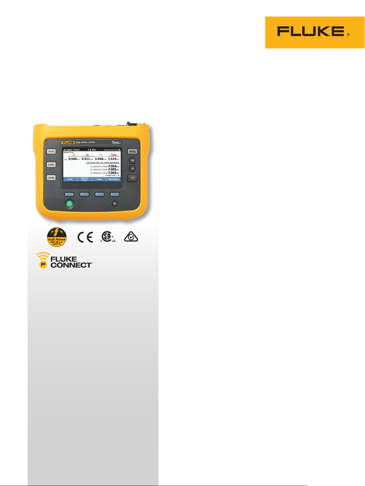
TECHNICAL DATA
Fluke 1732 and 1734
Three-Phase Electrical
Energy Loggers
Energy logging is now within your reach—discover
where you’re wasting energy, optimize your
facility’s energy use and reduce your bill
The new Fluke 1732 and 1734 Three-Phase Electrical Energy
loggers introduce a new simplicity to discovering sources of
electrical energy waste. Discover when and where energy in your
facility is being consumed; from the service entrance to individual
circuits. Access and share data remotely with your team via the
Fluke Connect
and make critical decisions in real-time, reducing the need for
protective equipment, site visits and check-ins.
Profiling energy usage across your facility helps you identify
opportunities for energy savings, and provides you with the data
you need to act on them. The new Energy Analyze software package allows you to compare multiple data points over time to build a
complete picture of energy usage, which is the first step to reduce
the cost of your energy bill.
®
app so you can maintain safer working distances
KEY MEASUREMENTS
Automatically capture and log voltage,
current, power, power factor, energy and
associated values
FLUKE CONNECT ® CO M PAT I BLE *
View data locally on the instrument, via
Fluke Connect mobile app and desktop
software or through your facilities’
WiFi infrastructure.
CONVENIENT INSTRUMENT
POWERING
Power instrument directly from the
measured circuit
HIGHEST SAFETY RATING
IN THE INDUSTRY
600 V CAT IV/1000 V CAT III rated for use
at the service entrance and downstream
• Measure all three phases: With included 3 flexible current
probes.
• Comprehensive logging: More than 20 separate logging
sessions can be stored on the instruments. In fact, all measured
values are automatically logged so you never loose measurement
trends. They can even be reviewed during logging sessions and
before downloading for real-time analysis.
• Optimized user interface: Quick, guided, graphical setup
ensures you’re capturing the right data every time, and the
intelligent verification function indicates correct connections
have been made, reducing user uncertainty.
• Bright, color touch screen: Perform convenient in-the-field
analysis and data checks with full graphical display.
• Optimized user interface: Capture the right data every
time with quick, guided, graphical setup and reduce
uncertainty about your connections with the intelligent
verification function.
• Complete “in-the-field” setup through the front panel
or Fluke Connect: No need to return to the workshop
for download and setup or to take a computer to the
electrical panel.
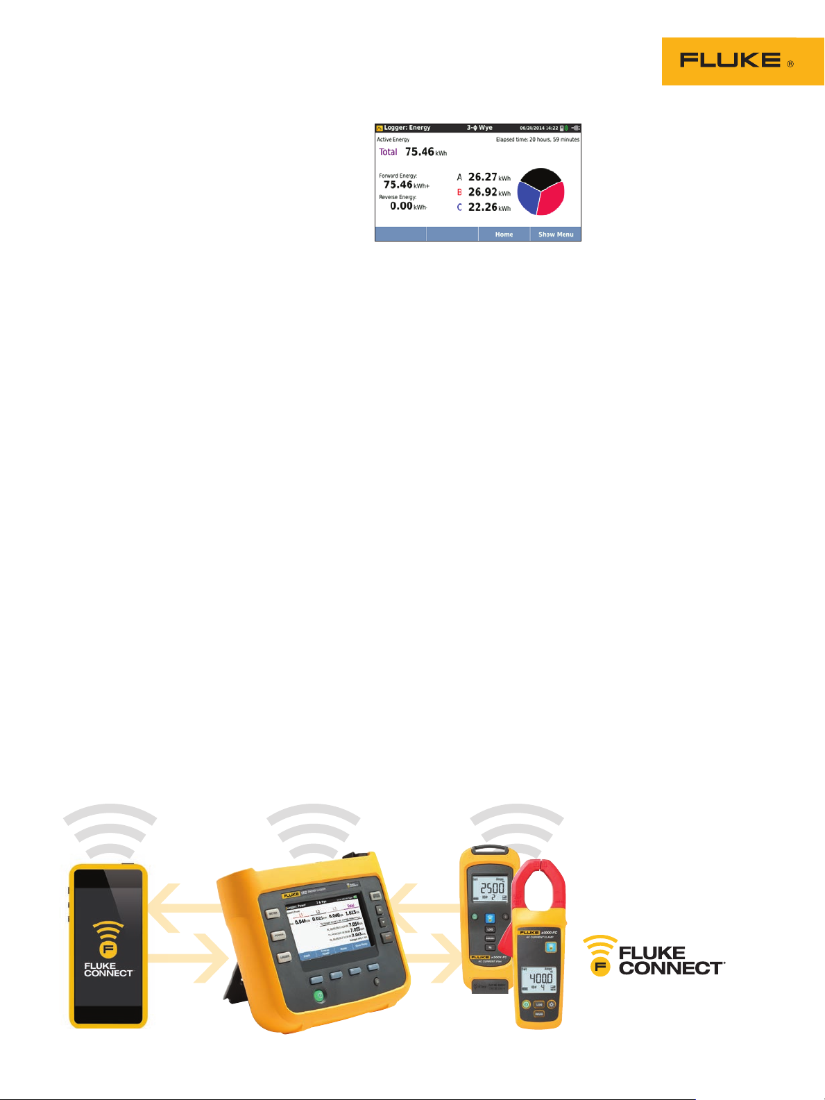
• Fully integrated logging: Connect other Fluke Connect devices
to the Fluke 1734 to simultaneously log up to two other measurement parameters, virtually any parameter available on a
Fluke Connect wireless digital multimeter or module.*
• Energy Analyze Plus application software: Download and
analyze every detail of energy consumption with our automated
reporting.
*Not al l models are available in all countries.
Check w ith your local Fluke representative.
Page 2
Applications
Load studies: Discover how much energy
individual pieces of equipment are consuming
when they are operating at minimum and
maximum capacity. Check capacity of circuits
prior to adding additional loads (various standards
exist for this process; in the US the NEC 22087 is the recommended standard). Load studies
can also identify situations where you may be
exceeding the allowable load on the circuit or
when an agreed peak demand applies from the
utility. For convenience, some load studies simply
measure current which makes installation of the
measuring equipment quick and easy. It is often
recommended that load surveys be performed
for 30 days so that all typical load conditions are
encountered during the test.
Energy assessments: quantify energy consumption before, and after improvements, to justify
energy saving devices
Energy surveys: Users often ask where measurements should be taken for an energy survey. The
answer is multiple points within the facility. Start
at the main service feeders; compare the power
and energy measured here with the readings
from the utility meter to ensure you’re receiving
the correct charges. Then move downstream to
the larger loads; these should be easy to identify by the current rating of the electrical panels
downstream of the service entrances. Measuring
at many points will allow a full picture of energy
usage across the facility to be developed. The
next question users typically have is how long an
energy survey should last. This of course depends
on the facility, but it is recommended that you
measure for a period that matches a typical facility activity period. If the facility operates over
a five day work week with down time on the
weekend, a seven day survey will most likely
capture typical conditions. If the facility operates
Conduct multiple studies with
one instrument; dow nload
while studies are in progress
via USB stick or Fluke Connect
mobile app.
Suitable for NEC 220 load st udies
at a constant level for 24 hours a day, 365 days a
year, a single day could be reasonably representative as long as you avoid a period where there
may be planned maintenance.
To capture a full picture of the facilities energy
usage it is not necessarily required to have
measurements made simultaneously at every
consumption point in the facility. To get a comprehensive picture, spot measurements can be
made and then compared on a sliding time timescale. For example, you could compare the service
entrance results from a typical Tuesday between
6:00 am and 12:00 pm with those of a larger load
in the facility. Typically there will be some correlation between these profiles.
Logging related analog measurements: When
conducting energy studies, it is useful to log
related analog measurements such as temperature, voltage, current or pressure. These variables
provide a better overall picture of operating
conditions and allow you to correlate asset
performance data with energy consumption.
Correlating these variables provides more of the
data you need to make cost saving performance
adjustments. With the Fluke 1734, up to two
Fluke Connect wireless modules can be used to
capture these measurements, and the values will
be automatically logged along with power and
energy readings.
2 Fluke Corporation Fluke 1732 and 1734 Three-Phase Electrical Energy Loggers
Use up to two Fluke Connect wireless
modules with the Fluke 1734 to capture
analog measurements
Page 3
Applications (continued)
Power and energy logging: When a piece of
equipment is operated it instantaneously consumes a specific amount of power in watts (W) or
kilowatts (kW). This power is accumulated over
the operating time and expressed as energy consumed in kilowatt hours (kWh). Energy is what
your electric utility charges for; there will be a
standard charge from the utility per kilowatt hour.
Utilities may have other additional charges, such
as peak demand, which is the maximum power
demand over a defined period of time, often 15 or
30 minutes.
There may also be power factor charges, which
are based on the effects of the inductive or
capacitive loads in the facility. Optimizing peak
demand and power factor often results in lower
monthly electricity bills. The 1733 and Fluke
1734 Three Phase Electrical Energy loggers have
the capability to measure and characterize these
effects enabling you to analyze the results and
save money.
Simplified load studies: For situations where
it’s either difficult or impractical to make a voltage connection the simple load study feature
allows users to perform a simplified load study by
measuring current only. The user can enter the
nominal expected voltage to create a simulated
power study. For accurate power and energy
studies it is required to monitor both voltage and
current but this simplified method is useful in
certain circumstances.
Log the most common parameters
Designed to measure the most critical threephase power parameters, the 1732 and 1734
can simultaneously log rms voltage, rms current, voltage, voltage and current THD, active
power, reactive power, power factor, active
energy, reactive energy, and more. With enough
memory for more than a year of data logging,
the 1732 and 1734 can discover which loads
are can be optimized to enable you to reduce
your energy bill.
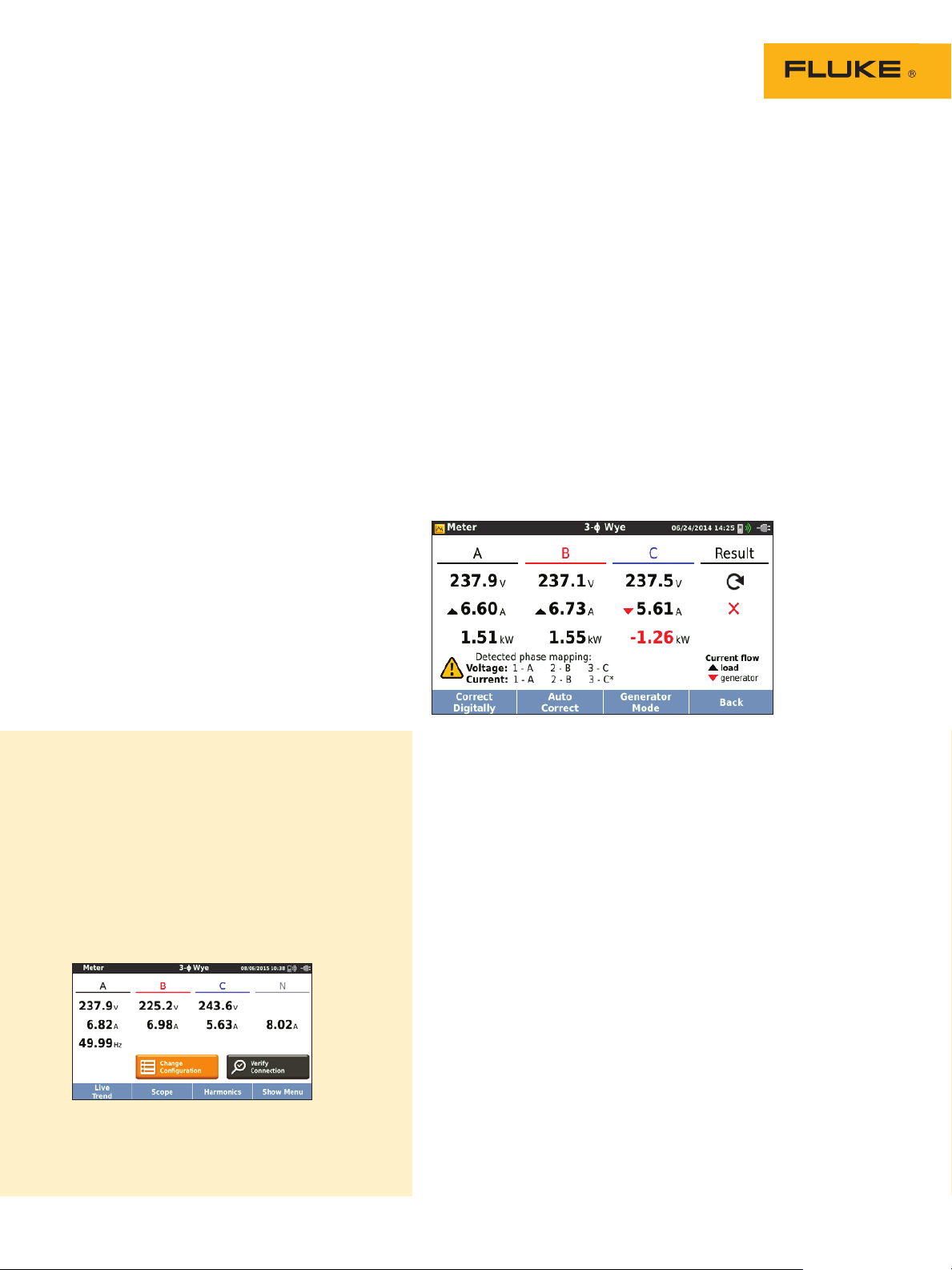
Easy to use
The four current probes are connected separately;
the instrument automatically detects and scales
the probes. The thin current probes are designed
to easily get through tight conductor spacing
and are easily set to 150 or 1500 A for high
accuracy in nearly any application. An innovative
tangle-free flat voltage lead makes connection
simple and reliable and the instrument’s intelligent ‘Verify Connection’ feature automatically
checks to make sure the instrument is connected
correctly and can digitally correct common
connection issues without having to disconnect
measurement leads.
The detachable power supply can be conveniently
and safely powered directly from the measured
circuit—no more searching for power outlets or
having to run multiple extension cords to the
logging location.
Intelligent verification function that digitally corrects most
common measurement connections
Data downloading couldn’t be easier or
more flexible:
• Download directly to a USB flash drive
that plugs directly into the USB port of the
instrument
• View measurements remotely via the Fluke
Connect mobile app and desktop software,
helping you maintain safer working distances
and reducing the need for personal protective
equipment and unnecessary site visits and
check-ins*
• Integrate energy measurement data along with
other plant maintenance data all in one place.
*Not al l models are available in all countries. Check with your
local Fluke representative.
Simple setup means all available measured
parameters are automatical ly selected during
logging so you can be su re you have the data
you need, even before you know you need it
3 Fluke Corporation Fluke 1732 and 1734 Three-Phase Electrical Energy Loggers
Page 4

Analysis and Reporting
Capturing logged data is just one part of the task.
Once you have the data, you need to create useful
information and reports that can be easily shared
and understood by your organization or customers. Fluke Energy Analyze Plus software makes
that task as simple as possible. With powerful
analysis tools and the ability to create customized
reports in minutes you’ll be able to communicate
your findings and quickly solve problems so you
can optimize system reliability and savings.
Quickly and easily compare any measured parameter
Specifications
Accuracy
Parameter Range Max. resolution
Voltage 1000 V 0.1 V ± (0.2 % + 0.01 %)
i17xx-flex 1500 12”
i17xx-flex 3000 24”
Current
i17xx-flex 6000 36”
i40s-EL clamp
Frequency 42.5 Hz to 69 Hz 0.01 H z ± (0.1 %)
Aux input ± 10 V dc 0.1 mV ± (0.2 % + 0.02 %)
Voltage min/max 1000 V 0.1 V ± (1 % + 0.1 %)
Current min/max
THD on voltage 1000 % 0.1 % ± 0.5
THD on current 1000 % 0.1 % ± 0.5
150 A
150 0 A
300 A
3000 A
600 A
6000 A
4 A
40 A
defined by
accessory
0.1 A
1 A
1 A
10 A
1 A
10 A
1 mA
10 m A
defined by
accessory
Intrinsic accuracy at reference conditions
(% of reading + % of full scale)
± (1 % + 0.02 %)
± (1 % + 0.02 %)
± (1 % + 0.03 %)
± (1 % + 0.03 %)
± (1.5 % + 0.03 %)
± (1.5 % + 0.03 %)
± (0.7 % + 0.02 %)
± (0.7 % + 0.02 %)
± (5 % + 0.2 %)
4 Fluke Corporation Fluke 1732 and 1734 Three-Phase Electrical Energy Loggers
Page 5

Intrinsic uncertainty ± (% of reading + % of range)
Parameter
Active Power P
Active Energy E
a
Apparent Power S
Apparent Energy E
ap
Reactive Power Q
Reactive Energy E
Additional uncertainty
in % of range
1
Range = 1000 V x Irange
Reference conditions:
• Environmental: 23 °C ± 5 °C, instrument operating for at least 30 minutes, no externa l electrical/magnetic field, RH <65 %
• Input conditions: Cos
• Current and power specifications: Input voltage 1 ph: 120 V/230 V or 3 ph wye/delta: 230 V/400 V Input c urrent: I > 10 % of Irange
• Primary conductor of clamps or Rogowski coil in center position
• Temperature coefficient: Add 0.1 x specified accuracy for each degree C above 28 °C or below 18 °C
r
1
Influence
quantity
PF ≥ 0.99 1.2 % + 0.005 %
0 ≤ PF ≤ 1 1.2 % + 0.005 %
0 ≤ PF ≤ 1 2.5 % of measured apparent power
V
> 250 V 0. 015 % 0.0225 % 0.0225 % 0. 015 %
P-N
ϕ/PF=1, Sinusoidal signal f=50 Hz/60 Hz, power supply 120 V/230 V ±10 %.
iF lex1500-12
150A/1500A
1
iFlex3000-24
300A/3000A
1.2 % +
0.0 075 %
1.2 % +
0.0 075 %
iFlex6000-36
600/6000A
1.7 % +
0.0 075 %
1.7 % +
0.0 075 %
i40s-EL
4A/40 A
1.2 % + 0.005 %
1.2 % + 0.005 %
Electrical specifications
Power supply
100 V to 500 V using safety plug input when powering from the
Voltage range
measurement circuit
100 V to 240 V using standard power cord (IEC 60320 C7)
Power consumption Maximum 50 VA (max. 15 VA when powered using IEC 60320 input)
Efficiency ≥ 68.2 % (in accordance with energy efficiency regulations)
Maximum no-load consumption < 0.3 W only when powered using IEC 60320 input
Mains power frequency 50/60 Hz ± 15 %
Battery Li-ion 3.7 V, 9.25 Wh, customer-replaceable
On-battery runtime Four hours in standard operating mode, up to 5.5 hours in power saving mode
Charging time < 6 hours
Data acquisition
Resolution 16-bit synchronous sampling
Sampling frequency 10.24 kHz at 50/60 Hz, synchronized to mains frequency
Input signal frequency 50/60 Hz (42.5 to 69 Hz)
Circuit types
1-ϕ, 1-ϕ IT, split phase, 3-ϕ delta, 3-ϕ wye, 3-ϕ wye IT, 3-ϕ wye balanced, 3-ϕ
Aron/Blondel (2-element delta), 3-ϕ delta open leg, currents only (load studies)
Data storage Internal flash memory (not user replaceable)
Memory size Typical 10 logging sessions of 8 weeks with 1-minute intervals
1
Basic interval
Measured parameters
Voltage, current, aux, frequency, THD V, THD A, power, power factor, fundamental
power, DPF, energy
Averaging interval User selectable: 1 sec, 5 sec, 10 sec, 30 sec, 1 min, 5 min, 10 min, 15 min, 30 min
Averaging time min/max values
Voltage, Current: Full cycle RMS updated every half cycle
Aux, Power: 200ms
Demand Interval (Energy Meter Mode)
Measured parameters Energy (Wh, varh, VAh), PF, maximum demand, cost of energy
Interval User selectable: 5 min, 10 min, 15 min, 20 min, 30 min, off
1
The num ber of possible logging sessions and logging period depends on user requirements.
5 Fluke Corporation Fluke 1732 and 1734 Three-Phase Electrical Energy Loggers
Page 6

Electrical specifications cont.
Standards compliance
Power IEEE 1459
Interfaces
USB-A File transfer via USB flash drive, firmware updates, max. supply current: 120 mA
WiFi File transfer and remote control via direct connection or WiFi infrastructure
®
Bluetooth
Read auxiliary measurement data from Fluke Connect
(requires 1734, or 1732 upgrade option)
3000 series modules
USB-mini Data download device to PC
Voltage inputs
Number of inputs 4 (3 phases and neutral)
Maximum input voltage 1000 Vrms, CF 1.7
Input impedance 10 M Ω
Bandwidth 42.5 Hz - 3.5 kHz
Scaling 1:1 and variable
Measurement category 1000 V CAT III/600 V CAT IV
Current inputs
Number of inputs 3, mode selected automatically for attached sensor
Input voltage Clamp input: 500 mVrms/50 mVrms; CF 2.8
Rogowski coil input
150 mVrms/15 mVrms at 50 Hz, 180 mVrms/18 mVrms at 60 Hz; CF 4; all at nominal
probe range
1 A to 150 A/10 A to 1500 A with thin flexible current probe i17XX-flex1500 12”
Range
3 A to 300 A/30 A to 3000 A with thin flexible current probe i17XX-flex3000 24”
6 A to 600 A/60 A to 6000 A with thin flexible current probe i17XX-flex6000 36”
40 mA to 4 A/0.4 A to 40 A with 40 A clamp i40s-EL
Bandwidth 42.5 Hz - 3.5 kHz
Scaling 1:1 and variable
Auxiliary inputs
Number of inputs 2
Input range 0 to ± 10 V dc, 1 reading/s
Scale factor Format: mx + b (gain and offset) user configurable
Displayed units User configurable (7 characters, for example, °C, psi, or m/s)
Wireless connection
Number of inputs 2
®
Supported modules Fluke Connect
3000 series
Acquisition 1 reading/s
6 Fluke Corporation Fluke 1732 and 1734 Three-Phase Electrical Energy Loggers
Page 7

Environmental specifications
Operating temperature -10 °C to +50 °C (14 °F to 122 °F)
Storage temperature -20 °C to +60 °C (−4 °F to 140 °F), with battery: -20 °C to +50 °C (−4 °F to 122 °F)
10 °C to 30 °C (50 °F to 86 °F) max. 95 % RH
Operating humidity
30 °C to 40 °C (86 °F to 104 °F) max. 75 % RH
40 °C to 50 °C (104 °F to 122 °F) max. 45 % RH
Operating altitude 2000 m (up to 4000 m derate to 1000 V CAT II/600 V CAT III/300 V CAT IV)
Storage altitude 12,000 m
Enclosure IP50 in accordance with EN60529
Vibration MIL-T-28800E, Type 3, Class III, Style B
IEC 61010-1
IEC Mains Input: Overvoltage Category II, Pollution Degree 2
Safety
Voltage Terminals: Overvoltage Category IV, Pollution Degree 2
IEC 61010-2-031: CAT IV 600 V/CAT III 1000 V
EN 61326-1: Industrial CISPR 11: Group 1, Class A
Electromagnetic compatibility
(EMC)
Korea (KCC): Class A Equipment (industrial broadcasting and
communication equipment)
USA (FCC): 47 CFR 15 subpart B. This product is considered an exempt device per
cl ause 15.103
Temperature coefficient 0.1 x accuracy specification/°C
General specifications
Color LCD display 4.3-inch active matrix TFT, 480 pixels x 272 pixels, resistive touch panel
Instrument and power supply: two-years (battery not included)
Warranty
Accessories: one-year
Calibration cycle: two-years
Instrument: 19.8 cm x 16.7 cm x 5.5 cm (7.8 in x 6.6 in x 2.2 in)
Dimensions
Power supply: 13.0 cm x 13.0 cm x 4.5 cm (5.1 in x 5.1 in x 1.8 in)
Instrument with power supply attached: 19.8 cm x 16.7 cm x 9 cm
(7.8 in x 6.6 in x 3.5 in)
Weight
Instrument: 1.1 kg (2.5 lb)
Power supply: 400 g (0.9 lb)
Tamper protection Kensington lock slot
7 Fluke Corporation Fluke 1732 and 1734 Three-Phase Electrical Energy Loggers
Page 8

i17xx-flex 1500 12” Flexible Current Probe specifications
Measuring range 1 to 150 A ac/10 to 1500 A ac
Nondestructive current 100 kA (50/60 Hz)
Intrinsic error at reference condition* ± 0.7 % of reading
Accuracy 173x + iFlex ± (1 % of reading + 0.02 % of range)
Temperature coefficient over operating temperature range 0.05 % of reading/°C, 0.09 % of reading/°F
Working voltage 1000 V CAT III, 600 V CAT IV
Probe cable length 305 mm (12 in)
Probe cable diameter 7.5 mm (0.3 in)
Minimum bending radius 38 mm (1.5 in)
Output cable length 2 m (6.6 ft)
Weight 115 g
Probe cable material TPR
Coupling material POM + ABS/PC
Output cable TPR/PVC
Operating temperature
-20 °C to +70 °C (-4 °F to 158 °F) temperature of
conductor under test shall not exceed 80 °C (176 °F)
Temperature, non-operating -40 °C to +80 °C (-40 °F to 176 °F)
Relative humidity, operating 15 % to 85 % non-condensing
IP rating IEC 60529:IP50
Warranty One-year
* Reference condition:
• Environmental: 23 °C ± 5 °C, no external electrical/magnetic field, RH 65 %
• Primary conductor in center position
8 Fluke Corporation Fluke 1732 and 1734 Three-Phase Electrical Energy Loggers
Page 9

Model features
1732 Energy Logger 1734 Energy Logger
FL U K E -1732 /B
Model
Functions
Fluke Connect module
support
(up to 2 modules**)
Recording
Trend
Communication
USB (mini B)
WiFi download of
instrument data
WiFi download via
WiFi access point
(requires
registration)**
Included Accessories
WiFi and BLE
adapter**
USB flash drive (4GB)
USB Cable
3PHV L-173 Flat Cable
1x red, 1x black 0.1m
cable
1x red, 1x black 1.5m
lead
Alligator clips 4 4 4 4 4 4 4
C173x Soft Case
Color Coding set
173 x-Hang e r kit Optional Optional Optional
MP1-Magnet Probe Optional Optional Optional 4 4 4 4
i173X-flex1500 12” Optional 3 3 Optional 3 3 3
Line cord
Compatible Optional Accessories
173X- AUX analog
adapter
i17XX-flex1500 12”
Current Probe
i17XX-flex3000 24”
Current Probe
i17XX-flex6000 36”
Current Probe
i40s-EL Current
Clamp
1732 to 1734 upgrade
(1732/UPGRA DE)
* Modules not included
** Not all model s are ava ila ble in all countrie s. Chec k with your loc al Flu ke representat ive.
Energy logger
basic version
Optional Optional Optional
• • • • • • •
• • • • • • •
• •
Optional Optional Optional Optional Optional Optional Optional
Optional Optional Optional Optional
• • • • • • •
• • • • • • •
• • • • • • •
• • • • • • •
• • • • • • •
• • • • • • •
• • • • • • •
EU, UK,
US, AU, BR
• • • • • • •
• • • • • • •
• • • • • • •
• • • • • • •
• • • • • • •
• • •
FLU K E -17 32 /
EUS
Energy logger
(EU and US)
EU, US, UK
FLU K E -17 32 /
INTL
Energy logger
(International)
Optional
EU, UK,
US, AU, BR
®
FLU K E -17 34/
EUS
Energy logger
with F luke
Connect
(EU and US)
•
EU, US, UK
FLU K E -17 34/ B
Energy logger
with F luke
Connect
• • • •
• •
• • • •
EU, UK,
US, AU, BR
– – – –
FLU K E -17 34/
INTL
Energy logger
with F luke
Connect
(International)
Optional Optional
Optional
EU, UK,
US, AU, BR
FLU K E -17 34/
Energy logger
with F luke
(International
wireless)
US, AU, BR
WINTL
Connect
•
EU, UK,
9 Fluke Corporation Fluke 1732 and 1734 Three-Phase Electrical Energy Loggers
Page 10

Ordering information**
FLU K E-1732/ B Energy Logger, Basic version
(excludes current probes)
FLUKE-1732/EUS Energy Logger, EU and US
version (includes current probes)
FLUKE-1732/INTL Energy Logger,
International version (includes current probes)
FLU K E-1734/B Energy Logger, with Fluke
Connect
FLUKE-1734/EUS Energy Logger, EU/US with
Fluke Connect (includes current probes)
FLUKE-1734/INTL Energy Logger,
International with Fluke Connect (includes
current probes)
FLUKE-1734/WINTL Energy Logger, International wireless version (includes current
probes)
Fluke 1732 includes:
Instrument, power supply, voltage test leads,
alligator clips (4x), 12 in 1,500A flexible
current probe (3x), soft case, Energy Analyze
Plus software, line cords, color coding set and
documentation on USB
flash drive
Fluke 1734 includes:
Instrument, power supply, voltage test leads,
alligator clips (4x), 12 in 1,500A flexible
current probe (3x), soft case, Energy Analyze
Plus software, magnetic hanging strap,
magnetic voltage probes (4x), WiFi/BLE
adapter**, line cords, color coding set and
documentation on USB flash drive
**Not all models are available in all cou ntries. Check with
your local Fluke representative.
®
(excludes current probes)
Preventive maintenance simplified. Rework eliminated.
Save time and improve the reliability of your maintenance data by
wirelessly syncing measurements using the Fluke Connect® system.
• Eliminate data-entry errors by saving measurements directly from the
tool and associating them with the work order, report or asset record.
• Maximize uptime and make confident maintenance decisions with data
you can trust and trace.
• Access baseline, historical and current measurements by asset.
• Move away from clipboards, notebooks and multiple spreadsheets with
a wireless one-step measurement transfer.
• Share your measurement data using ShareLiveTM video calls and emails.
• The Fluke 1732 and 1734 Three-Phase Electrical Energy Loggers are
part of a growing system of connected test tools and equipment
maintenance software. Visit the website to learn more about the
Fluke Connect system.
Find out more at flukeconnect.com
All t radema rks are the property of their respective owner s. WiF i or cellular serv ice req uir ed to sha re
data. Smartphone, w ireless ser vice and data plan not i nclude d with purchase. Fi rst 5 GB of storage is
free. P hone support det ails can be v iewed at f luke.com/phones.
Smart phone wireless service and data plan not included w ith purchase. Fluke Connect
is not available in all countries.
Fluke. Keeping your world up and running.
Fluke Corporation
PO Box 9090, Everett, WA 98206 U.S.A.
Fluke Europe B.V.
PO Box 1186, 5602 BD
Eindhoven, The Netherlands
10 Fluke Corporation Fluke 1732 and 1734 Three-Phase Electrical Energ y Loggers
For more information call:
In the U.S.A. (800) 443-5853 or
Fax (425) 446-5116
In Europe/M-East/Africa
+31 (0)40 267 5100 or
Fax +31 (0)40 267 5222
In Canada (800) 36-FLUKE or
Fax (905) 890-6866
®
From other countries +1 (425) 446-5500 or
Fax +1 (425) 446-5116
Web: www.fluke.com
©2017 Fluke Corporation.
Specifications subject to change without notice.
Printed in U.S.A. 1/2017 6008068b-en
Modification of this document is not permitted
without written permission from Fluke Corporation.
 Loading...