


GB
Dec 2006, Rev. 1, 09/2009
© 2006, 2009 Fluke Corporation, All rights reserved. Printed in The Netherlands
All product names are trademarks of their respective companies.
Fluke 125
Industrial ScopeMeter
Getting Started
®
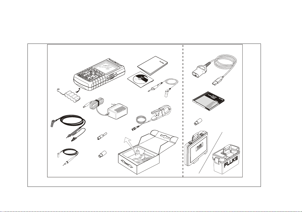
Contents of the Fluke 125 Test Tool Kit
(2x)
(3x)
S-Version
Figure 1. Fluke 125 Test Tool Kit

Getting Started
Introduction
This Getting Started Manual provides basic information
on the Fluke 125 ScopeMeter Test Tool. For complete
operating instructions, refer to the Users Manual on the
accompanying CD-ROM
Contacting a Service Center
To locate a Fluke authorized service center, visit us on
the World Wide Web at: www.fluke.com
or call Fluke using any of the phone numbers listed
below:
+1-888-993-5853 in the U.S.A and Canada
+31-40-2675200 in Europe
+1-425-446-5500 from other countries.
Safety Information: Read First
The Fluke 125 ScopeMeter Test Tool (hereafter referred
to as “Test Tool”) complies with:
• ANSI/ISA-82.02.01
• EN/IEC 61010-1: 2001 600 V Measurement
Category III, Pollution Degree 2
• CAN/CSA-C22.2 No.61010-1-04 (including
CSAUS approval)
C
Use the Test Tool only as specified in the Users Manual.
Otherwise, the protection provided by the Test Tool might
be impaired.
A Warning identifies conditions and actions that pose
hazard(s) to the user. A Caution identifies conditions and
actions that may damage the Test Tool.
1

Fluke 125
Getting Started
Warning
To avoid electrical shock or fire:
• Use only the power supply, Model PM8907
(Battery Charger / Power Adapter).
• Before use check that the selected/indicated
voltage range on the PM8907 matches the
local line power voltage and frequency.
• For the PM8907/808 universal Battery
Charger/Power Adapter use only line cords
that comply with the local safety regulations.
Note
To accommodate connection to various line power
sockets, the PM8907/808 universal Battery Charger /
Power Adapter is equipped with a male plug that must
be connected to a line cord appropriate for local use.
Since the adapter is isolated, the line cord does not
need to be equipped with a terminal for connection to
protective ground. Since line cords with a protective
grounding terminal are more commonly available you
might consider using these anyhow.
The 230V rating of the PM8907/808 is not for use in
North America. A line plug adapter complying with the
applicable National Requirements may be provided to
alter the blade configurations for a specific country.
Warning
To avoid electrical shock or fire if a Test Tool
input is connected to more than 42 V peak (30
Vrms) or on circuits of more than 4800 VA:
• Use only insulated voltage probes, test leads
and adapters supplied with the Test Tool, or
indicated as suitable for the Fluke 125 Test
Tool.
• Before use, inspect voltage probes, test leads
and accessories for mechanical damage and
replace when damaged.
• Remove all probes, test leads and
accessories that are not in use.
• Always connect the battery charger first to
the ac outlet before connecting it to the Test
Tool.
• Do not apply input voltages above the rating
of the instrument. Use caution when using 1:1
test leads because the probe tip voltage w ill
be directly transmitted to the Test Tool.
• Do not use exposed metal BNC or banana
plug connectors.
• Do not insert metal objects into connectors.
• Always use the Test Tool only in the manner
specified.
2

Getting Started
Preparing for Use
Max. Input Voltages
Input A and B directly ...............................600 V CAT III
Input A and B via BB120 ..........................300 V CAT III
Input A and B via STL120.........................600 V CAT III
Max. Floating Voltage
From any terminal to ground ....................600 V CAT III
Voltage ratings are given as “working voltage”. They
should be read as Vac-rms (50-60 Hz) for AC sine
wave applications and as Vdc for DC applications.
Measurement Category III refers to distribution level and
fixed installation circuits inside a building.
The isolated input connectors have no exposed metal and
are fully insulated to protect against electrical shock.
If Safety Features are Impaired
Use of the Test Tool in a manner not specified may
impair the protection provided by the equipment.
Before use, inspect the test leads for mechanical damage
and replace damaged test leads!
Whenever it is likely that safety has been impaired, the
Test Tool must be turned off and disconnected from the
line power. The matter should then be referred to qualified
personnel. Safety is likely to be impaired if, for example,
the Test Tool fails to perform the intended measurements
or shows visible damage.
Preparing for Use
At delivery, the installed rechargeable batteries may be
empty. To reach full charge they must be charged for 7
hours with the Test Tool turned off:
• use only the supplied Battery Charger/Power Adapter
model PM8907
• before use check that the PM8907 voltage and
frequency range match the local line power range
• connect the battery charger to the ac outlet
• connect the battery charger to the POWER ADAPTER
input on the right-hand side of the Test Tool.
Caution
To prevent decrease of the battery capacity,
you must charge the batteries at least once a
year.
3

Fluke 125
Getting Started
Powering/Resetting the Test Tool
Turning power on/off:
The Test Tool powers up in its last
setup configuration.
Resetting the Test Tool to the factory (default) settings:
+
Turn power off, then press and hold the
Backlight key and turn on again. You
should hear a double beep.
Changing Backlight and Contrast
To save battery power, the screen can be set to an
economic brightness display when operated on the battery
pack (with no power adapter connected).
Note
Using dimmed display lengthens maximum
battery power operation time.
To change the brightness and contrast:
Open the LIGHT/CONTRAST button
bar.
Dim / Brighten the backlight.
Press CONTRAST.
Adjust the Contrast of the display.
Reading the Screen
The screen is divided into three areas that are indicated in
Figure 2. The areas are:
Reading area
only input A is on, you will see the input A readings only. If
input B is on you will also see the input B readings.
Waveform area (B): Displays the Input A(B) waveform.
The trace identifier (A) is visible on the left of the
waveform. The zero icon (-) identifies the ground level of
the waveform. The bottom line displays the ranges / div
and the power indicator (line or battery).
When battery powered, the battery indicator
informs you about the condition of the battery
from full to empty:
(A): Displays the numeric readings. If
Note:
4
Press LIGHT.
 Loading...