

Page 1

114, 115, and 117
True-rms Multimeters
Gebruiksaanwijzing
PN 2572573
July 2006, Rev. 1, 2/07 (Dutch)
© 2006, 2007 Fluke Corporation. All rights reserved. Printed in China.
All product names are trademarks of their respective companies.
®
Page 2

BEPERKTE GARANTIE EN BEPERKING VAN AANSPRAKELIJKHEID
Dit product van Fluke is vrij van materiaal- en fabricagefouten gedurende 3 jaar
na de datum van aankoop. Deze garantie is niet van toepassing op zekeringen,
wegwerpbatterijen of schade die voortvloeit uit een ongeluk, verwaarlozing, verkeerd
gebruik, wijziging, verontreiniging of abnormale omstandigheden bij bediening of
hantering. Wederverkopers zijn niet gemachtigd om enige andere garantie namens
Fluke te verstrekken. Voor het verkrijgen van service gedurende de garantieperiode
moet u bij het dichtstbijzijnde door Fluke erkende servicecentrum om retourautorisatieinformatie vragen en het product vervolgens samen met een beschrijving van het
probleem naar dat centrum sturen.
DEZE GARANTIE IS UW ENIGE VERHAAL. ER WORDEN GEEN ANDERE
UITDRUKKELIJKE OF STILZWIJGENDE GARANTIES, ZOALS GESCHIKTHEID
VOOR EEN BEPAALD DOEL, VERSTREKT. FLUKE IS NIET AANSPRAKELIJK
VOOR BIJZONDERE, INDIRECTE, INCIDENTELE OF BIJKOMENDE SCHADE OF
VERLIES, VOORTVLOEIEND UIT WELKE OORZAAK OF THEORIE DAN OOK.
Aangezien in bepaalde staten of landen de uitsluiting of beperking van een
stilzwijgende garantie of van incidentele schade of gevolgschade niet is toegestaan,
is het mogelijk dat deze beperking van aansprakelijkheid niet op u van toepassing is.
11/99
Fluke Corporation
P.O. Box 9090
Everett, WA 98206-9090
VS
Fluke Europe B.V.
P.O. Box 1186
5602 BD Eindhoven
Nederland
Page 3

True-rms Multimeters
Inleiding
De Fluke meters, model 114, model 115 en model 117,
zijn op batterijen werkende, true-rms-multimeters
(hierna ‘de meter’ genoemd) met een display met
6000 digits en een staafdiagram. Deze
gebruiksaanwijzing is van toepassing op alle drie de
modellen. Alle afbeeldingen tonen model 117.
Deze meters voldoen aan de normen van CAT III IEC
nd
61010-1 2
1 2nd Edition definieert vier meetcategorieën (CAT I t/m
IV) op basis van de omvang van het door
stootspanningen teweeggebrachte gevaar. CAT IIImeters bieden bescherming tegen stootspanningen in
vaste installaties op het verdeelniveau.
Contact opnemen met Fluke
Bel een van de volgende nummers om contact op te
nemen met Fluke:
Edition. De veiligheidsnorm van IEC 61010-
VS: 1-888-99-FLUKE (1-888-993-5853)
Canada: 1-800-36-FLUKE (1-800-363-5853)
Europa: +31 402-675-200
Japan: +81-3-3434-0181
Singapore: +65-738-5655
Vanuit andere landen: +1-425-446-5500
U kunt ook de website van Fluke bezoeken op
www.fluke.com
Registreer de meter op register.fluke.com
Onveilige spanning
Het symbool Y attendeert u op een potentieel
gevaarlijke spanning als de meter een spanning
≥ 30 V of een overspanning (OL, overload) meet. Bij
frequentiemetingen >1 kHz wordt het symbool Y
niet gespecificeerd.
Meetkabelwaarschuwing
LEAd
gegeven, als u de draaiknop in
(ampère) zet, om u eraan te herinneren te
controleren of de meetkabels in de juiste
aansluitingen steken.
.
.
XWWaarschuwing
Als u probeert om een meting te
verrichten met een kabel in een
onjuiste aansluiting, kunt u lichamelijk
letsel oplopen of kan de meter
worden beschadigd.
verschijnt kort en er wordt een korte pieptoon
en uit de A-stand
1
Page 4

114, 115 and 117
Gebruiksaanwijzing
Veiligheidsinformatie
XWWaarschuwing wijst op gevaarlijke omstandigheden en handelingen die lichamelijk of dodelijk letsel kunnen
veroorzaken.
WLet op wijst op omstandigheden en handelingen die de meter of de te testen apparatuur kunnen beschadigen.
Neem de volgende voorschriften in acht om elektrische schok of lichamelijk letsel
te voorkomen:
• Gebruik de meter uitsluitend zoals gespecificeerd in deze gebruiksaanwijzing. Anders is het
mogelijk dat de meter niet de voorziene bescherming biedt.
• Gebruik de meter of de meetkabels niet als deze er beschadigd uitzien of als u vermoedt dat
de meter niet naar behoren werkt.
• Gebruik altijd de juiste aansluitingen, de juiste knopstand en het juiste bereik voor
de metingen.
• Controleer of de meter naar behoren werkt door een bekende spanning te meten. Als u niet
zeker bent, moet u de meter laten nakijken.
• Pas nooit meer dan de op de meter vermelde nominale spanning toe tussen de aansluitingen
of tussen een aansluiting en aarde.
• Wees voorzichtig als de spanning hoger is dan 30 V ac-rms, 42 V ac-piek of 60 V dc. Een
dergelijke spanning kan elektrische schok veroorzaken.
• Schakel de stroom naar het circuit uit en ontlaad alle hoogspanningscondensators voordat u
de weerstand, continuïteit, dioden of capaciteit meet.
• Gebruik de meter niet in de omgeving van ontplofbaar gas of ontplofbare dampen.
• Houd uw vingers achter de vingerbescherming wanneer u de meetkabels of probes gebruikt.
• Gebruik uitsluitend door een veiligheidsinstituut goedgekeurde meetkabels met dezelfde
nominale spanning, categorie en stroomsterkte als de meter.
2
Page 5
True-rms Multimeters
Veiligheidsinformatie
• Neem de meetkabels uit de meter voordat u de batterijklep of de meterbehuizing opent.
• Neem de plaatselijke en landelijke veiligheidsvoorschriften in acht wanneer u werkt op
gevaarlijke locaties.
• Gebruik de door de plaatselijke en landelijke overheid vereiste veiligheidsuitrusting wanneer
u werkt op gevaarlijke locaties.
• Werk niet alleen.
• Vervang de zekering uitsluitend door de vermelde reservezekering omdat anders de
voorziene bescherming wellicht niet wordt geboden.
• Controleer de continuïteit van de meetkabels vóór gebruik. Gebruik de meter niet bij hoge
aflezingen of aflezingen met ruis.
• Gebruik de functie autovoltage niet om de spanning te meten in circuits die door de lage
ingangsimpedantie (≈3 kΩ) van deze functie beschadiging kunnen oplopen (alleen 114 en 117).
B Ac (wisselstroom) I Zekering
F Dc (gelijkstroom) T Dubbel geïsoleerd
X Gevaarlijke spanning W Belangrijke informatie; zie gebruiksaanwijzing
Batterij (als symbool in display verschijnt,
N
is de batterij bijna leeg)
Werp dit product niet met gewoon vast
afval weg. Neem contact op met Fluke of
~
een erkend recyclingbedrijf om het product
af te voeren.
Symbolen
J Aarde
D Ac en dc
3
Page 6
114, 115 and 117
Gebruiksaanwijzing
Display
6
5
4
3
2
1
16
15
VoltAlert
7
14
17
8
9
11
18
10
12
13
edy02f.eps
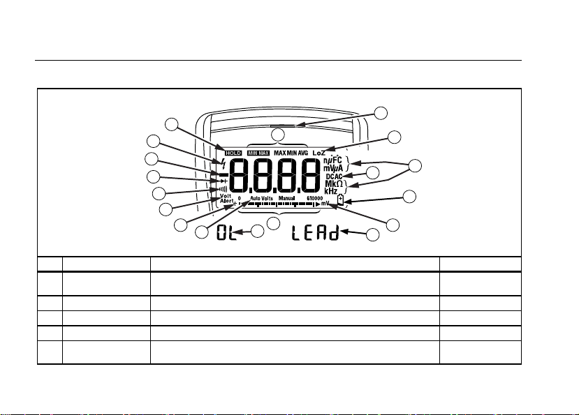
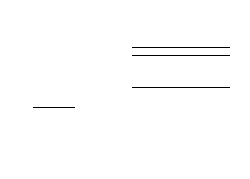
Nr. Symbool Betekenis Model
A w De meter staat in de modus VoltAlert™ (contactloze
spanningsdetectie).
B s De meterfunctie is ingesteld op continuïteit.
C R De meterfunctie is ingesteld op diodetest.
D O Ingangswaarde is negatief.
E
Y
X Onveilige spanning. Gemeten ingangsspanning ≥ 30 V of
overspanning (OL)
117
114, 115 en 117
115 en 117
114, 115 en 117
114, 115 en 117
4
Page 7
True-rms Multimeters
Display
F K Display HOLD is ingeschakeld. Het display bevriest de huidige
G M
VWX
H (Rood ledje) Contactloze VoltAlert sensor neemt spanning waar.
I
J nµF mVµA
K DC AC Gelijkstroom of wisselstroom.
L
M 610000 mV Geeft het meetbereik van de meter weer.
N (staafdiagram) Analoog display.
O Auto Volts
P + Polariteit van staafdiagram.
Q 0L W De ingangswaarde is te groot voor het geselecteerde bereik.
R LEAd W Meetkabelwaarschuwing. Verschijnt kort als de draaiknop in
LoZ
MkΩ kHz
N
Auto
Manual
aflezing.
De modus MIN MAX AVG is ingeschakeld.
Maximum-, minimum-, gemiddelde of huidige aflezing verschijnt.
De meter meet spanning of capaciteit met een lage
ingangsimpedantie.
Meeteenheden.
Waarschuwing voor batterij bijna leeg.
De meter staat in de functie autovoltage.
Automatisch bereik. De meter selecteert het bereik met de
beste resolutie.
Handmatig bereik. De gebruiker stelt het bereik in.
en uit de A-stand wordt gezet.
114, 115 en 117
114, 115 en 117
117
114, 115 en 117
114, 115 en 117
114, 115 en 117
114, 115 en 117
114, 115 en 117
114, 115 en 117
114 en 117
114, 115 en 117
114, 115 en 117
114, 115 en 117
114, 115 en 117
115 en 117
5
Page 8
114, 115 and 117
Gebruiksaanwijzing
Aansluitingen
1
A
10 A
FUSED
COM
V
3
2
edy01f.eps
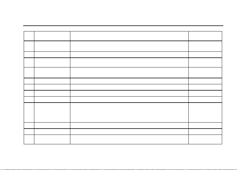
Nr. Omschrijving Model
Ingang voor meting van ac- en dc-stroom tot 10 A.
A
Aardeaansluiting (retouraansluiting) voor alle metingen.
B
Ingang voor het meten van spanning, continuïteit, weerstand, capaciteit en
C
frequentie en voor het testen van dioden.
115 en 117
114, 115 en 117
114, 115 en 117
Foutberichten
bAtt Batterij vervangen, anders werkt meter niet.
CAL Err Kalibratie vereist. Meter kalibreren, anders werkt meter niet.
EEPr Err Interne fout. Meter reparere n, anders werkt meter niet.
F11 Err Interne fout. Meter repareren, anders werkt meter niet.
6
Page 9

True-rms Multimeters
Standen van draaiknop
Standen van draaiknop
Stand
draaiknop
x
e
Hz (toets)
D
l
Ω
s
R
S
j
Hz (toets)
I
w
Opmerking: Alle ac-functies en Auto-V LoZ zijn true-rms. Ac-spanning is ac-gekoppeld. Auto-V LoZ, Ac-mV
en Ac-A zijn dc-gekoppeld.
Selecteert automatisch ac- of dc-spanning op basis van de waargenomen
ingangsspanning met een lage ingangsimpedantie.
Ac-spanning van 0,06 tot 600 V.
Frequentie van 5 Hz tot 50 kHz.
Dc-spanning van 0,001 V tot 600 V. 114, 115 en 117
Ac-spanning van 6,0 tot 600 mV, dc-gekoppeld. Dc-spanning van 0,1 mV
tot 600 mV.
Weerstand van 0,1 Ω tot 40 MΩ.
Pieptoon wordt bij < 0 Ω ingeschakeld en bij > 50 Ω uitgeschakeld. 114, 115 en 117
Diodetest. Geeft overspanning boven 2,0 V weer. 115 en 117
Farad van 1 nF tot 9999 μF.
Ac-stroom van 0,1 A tot 10 A (> 10 tot 20 A, 30 seconden aan, 10 minuten
uit). > 10,00 A: display knippert. > 20 A: OL verschijnt. Dc-gekoppeld.
Frequentie van 45 Hz tot 5 kHz.
Dc-stroom van 0,001 A tot 10 A (> 10 tot 20 A, 30 seconden aan, 10 minuten
uit). > 10,00 A: display knippert. > 20 A: OL verschijnt.
Contactloze detectie van ac-spanning.
Meetfunctie Model
114 en 117
114, 115 en 117
115 en 117
114, 115 en 117
114, 115 en 117
115 en 117
115 en 117
115 en 117
117
7
Page 10

114, 115 and 117
Gebruiksaanwijzing
Batterijbesparing (rustmodus)
De meter gaat automatisch op rustmodus over en het display
wordt leeggemaakt, als u gedurende 20 minuten de functie
en het bereik ongewijzigd laat en geen toets indrukt. Door
een willekeurige toets in te drukken of aan de draaiknop te
draaien, activeert u de meter. Als u de rustmodus niet wilt
gebruiken, houdt u de toets g ingedrukt wanneer u de
meter aanzet. De rustmodus is altijd uitgeschakeld in de
modus MIN MAX AVG.
MIN MAX AVG-registratiemodus
De MIN MAX AVG-registratiemodus registreert de minimumen maximumingangswaarden (negeert overspanning) en
berekent een lopend gemiddelde van alle aflezingen. Als een
nieuwe maximum- of minimumwaarde wordt waargenomen,
piept de meter.
• Zet de meter in de gewenste meetfunctie en het gewenste
meetbereik.
• Druk op p om de modus MIN MAX AVG in
te chakelen.
• Men MAX lichten op en de hoogste aflezing
verschijnt die is waargenomen sinds MIN MAX AVG is
ingeschakeld.
• Druk op p om de lage (MIN), gemiddelde (AVG) en
huidige aflezingen te doorlopen.
f om de MIN MAX AVG-registratie stil te
• Druk op
leggen zonder de opgeslagen waarden te wissen.
K verschijnt.
8
• Druk nogmaals op fom de MIN MAX AVG-registratie
te hervatten.
• Druk gedurende ten minste 1 seconde op
aan de draaiknop om af te sluiten en de opgeslagen
aflezingen te wissen.
Display HOLD
Denk eraan dat als display HOLD is
ingeschakeld, het display niet
verandert wanneer u een andere
spanning toepast om elektrische
schokken te voorkomen.
De meter bevriest het display in de modus display HOLD.
1. Druk op f om display HOLD in te schakelen.
(K verschijnt.)
2. Druk op f of draai aan de draaiknop om terug te
keren naar de normale werking.
Achtergrondverlichting
Druk op
Q om de achtergrondverlichting aan of uit te zetten.
De achtergrondverlichting wordt na 40 minuten automatisch
uitgeschakeld. Als u de automatische uitschakeling van de
achtergrondverlichting niet wilt gebruiken, houdt u de toets
Q ingedrukt wanneer u de meter aanzet.
Handmatig bereik en automatisch bereik
De meter beschikt over de modi handmatig bereik en
automatisch bereik.
XWWaarschuwing
p of draai
Page 11
True-rms Multimeters
Opstartopties
• In de modus automatisch bereik selecteert de meter het
bereik met de beste resolutie.
• In de modus handmatig bereik wordt automatisch bereik
genegeerd en selecteert u zelf het bereik.
Als u de meter aanzet, wordt automatisch bereik standaard
ingeschakeld en verschijnt Auto.
1. Druk op
2. In de modus handmatig bereik drukt u op
3. Druk gedurende ten minste 1 seconde op
Opstartopties
Om een opstartoptie te selecteren, houdt u de
corresponderende toets (zie tabel hieronder) ingedrukt
q om de modus handmatig bereik in te
schakelen. Manual verschijnt.
bereik stapsgewijs te verhogen. Na het hoogste bereik
gaat de meter terug naar het laagste bereik.
U kunt het bereik in de modus MIN MAX AVG of
de modus display HOLD niet handmatig wijzigen.
Als u op qdrukt wanneer de meter in MIN MAX
AVG of display HOLD staat, geeft de meter twee
pieptonen om aan te geven dat dit een ongeldige
bewerking is en wordt het bereik niet veranderd.
draai aan de draaiknop om handmatig bereik af te
sluiten. De meter keert terug naar automatisch bereik
en Auto verschijnt.
Opmerking
qom het
q of
wanneer u de meter aanzet. De opstartopties worden
geannuleerd wanneer u de meter uitzet of als de meter op
rustmodus overgaat.
Toets Opstartopties
f
p
q
g
Basismetingen
De afbeeldingen op de volgende pagina’s illustreren de
basismetingen.
Als u de meetkabels op het circuit of het apparaat aansluit,
moet u het aardsnoer (COM) aansluiten voordat u de onder
stroom staande kabel aansluit; als u de meetkabels
verwijdert, moet u de onder stroom staande kabel
verwijderen voordat u het aardsnoer verwijdert.
Zet alle segmenten van het display aan.
Schakelt de pieptoon uit. bEEP verschijnt
als de pieptoon aanstaat.
Schakelt capaciteitsmetingen bij lage
impedantie in. LCAP verschijnt als deze
functie aanstaat. Zie pagina 14.
Deactiveert automatische uitschakeling
(rustmodus). PoFF verschijnt als
rustmodus is geactiveerd.
Deactiveert automatische uitschakeling
van achtergrondverlichting. LoFF
Q
verschijnt als deze functie aanstaat.
9
Page 12
114, 115 and 117
Gebruiksaanwijzing
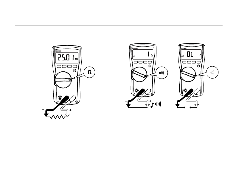
Weerstand meten
XWWaarschuwing
Om elektrische schok, letsel of
beschadiging aan de meter te voorkomen,
schakelt u de stroom naar het circuit uit
en ontlaadt u alle hoogspanningscondensators voordat u de weerstand,
continuïteit, dioden of capaciteit meet.
10
edy04f.eps
Continuïteit testen
De continuïteitsfunctie werkt het best als een
snelle, eenvoudige methode om open en
kortgesloten circuits te controleren. Gebruik de
weerstandsfunctie (e) van de meter om
maximale nauwkeurigheid te verkrijgen bij
weerstandsmetingen.
Opmerking
edy06f.eps
Page 13
True-rms Multimeters
Basismetingen
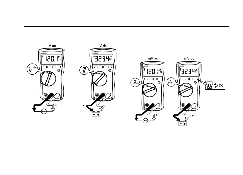
Wissel- en gelijkspanning meten
eee03f.eps
Autovoltage gebruiken (alleen 114 en 117)
Wanneer de draaiknop op x staat, selecteert de meter
automatisch een dc- of ac-spanningsmeting op basis van het
aangelegde ingangssignaal tussen de ingangen V of + en COM.
Deze functie stelt de ingangsimpedantie van de meter in op
ongeveer 3 kΩ om de kans op foutieve aflezingen als gevolg
van fantoomspanning te beperken.
Wissel- en gelijkspanning meten in millivolt
Wanneer de draaiknop op l staat, meet de meter ac-mV
en dc-mV. Druk op g om de meter op dc-mV te zetten.
eee18f.eps
11
Page 14

114, 115 and 117
Gebruiksaanwijzing
Ac- of dc-stroom (115 en 117)
Ga als volgt te werk om lichamelijk letsel of
beschadiging van de meter te voorkomen:
• Probeer nooit de stroom in een
stroomkring te meten als de
nullastpotentiaal naar aarde > 600 V is.
• Controleer de zekering van de meter
voordat u metingen verricht. (Zie
‘Zekering testen’.)
• Gebruik de juiste aansluitingen, de juiste
stand van de draaiknop en het juiste
bereik voor uw metingen.
• Schakel de probes nooit parallel met een
circuit of component als de meetkabels in
de A-aansluitingen (ampère) steken.
XWWaarschuwing
12
1
A
2 3
edy08f.eps
Schakel de stroom naar het circuit uit, verbreek het circuit,
plaats de meter in serie met het circuit en zet de stroom
opnieuw aan.
Page 15

True-rms Multimeters
Basismetingen
Stroom boven 10 A meten
De millivolt-/spanningsfunctie van de meter kan worden
gebruikt met een optionele stroomprobe met mV/A-uitgang
om stroom te meten die hoger is dan de nominale stroom
van de meter. Controleer of de meter in de juiste stand staat
voor de stroomprobe (ac of dc). Raadpleeg een Fluke
catalogus of neem contact op met uw plaatselijke Fluke
vertegenwoordiger voor compatibele stroomklemmen.
edy14f.eps
Capaciteit meten (alleen 115 en 117)
edy05f.eps
13
Page 16

114, 115 and 117
Gebruiksaanwijzing
Frequentie meten (alleen 115 en 117)
Om elektrische schokken te voorkomen, moet
u het staafdiagram negeren bij frequenties >
1 kHz. Als de frequentie van het gemeten
signaal > 1 kHz is, zijn het staafdiagram en Z
niet gespecificeerd.
De meter meet de frequentie van een signaal door het aantal
keren te tellen dat het signaal per seconde een triggerniveau
overschrijdt. Het triggerniveau is 0 V, 0 A voor alle bereiken.
XWWaarschuwing
eee09f.eps
14
Druk op g om de frequentiemeting in en uit te schakelen.
Frequentie werkt uitsluitend met ac-functies.
Bij frequentiemetingen tonen het staafdiagram en de
bereikindicator de aanwezige ac-spanning of stroom.
Selecteer steeds lagere bereiken aan de hand van handmatig
bereik voor een stabiele aflezing.
Detectie van ac-spanning (alleen 117)
eee13f.eps
Page 17

True-rms Multimeters
Basismetingen
Voor de detectie van ac-spanning plaatst u de top van de meter
in de nabijheid van een geleider. Bij detectie van spanning geeft
de meter een geluids- en visueel signaal. Er zijn twee instellingen
voor gevoeligheid. De stand Lo wordt gebruikt bij gelijk met de
muur geïnstalleerde wandcontactdozen, stekkerblokken, gelijk
met de muur geïnstalleerde industriële stopcontacten en diverse
netsnoeren. De stand Hi wordt gebruikt voor de detectie van acspanning bij andere soorten verzonken connectors of
stopcontacten waar de eigenlijke ac-spanning binnen in de
connector is verzonken. De VoltAlert sensor werkt in
toepassingen met onbeklede draad en met spanningen tot
minimaal 24 V in de stand Hi.
Bij afwezigheid van enig signaal kan er
toch spanning staan. De VoltAlert sensor
is niet betrouwbaar met afgeschermde
draad. De werking van de sensor wordt
mogelijk beïnvloed door verschillen in
contactdoosontwerp, isolatiedikte en
type isolatie.
Capaciteitsmetingen bij lage impedantie (alleen 115 en 117)
Voor capaciteitsmetingen op kabels met fantoomspanning
houdt u qingedrukt wanneer u de meter aanzet. Dit brengt
de meter in de capaciteitsmodus LoZ (lage ingangsimpedantie).
In deze modus zijn de capaciteitsmetingen minder nauwkeurig
en is hun dynamische bereik lager. Deze stand wordt niet
opgeslagen wanneer u de meter uitzet of als de meter op
rustmodus overgaat.
XW Waarschuwing
Dioden testen (115 en 117)
eee07f.eps
15
Page 18

114, 115 and 117
Gebruiksaanwijzing
Staafdiagram gebruiken
Het staafdiagram functioneert zoals de naald van een
analoge meter. Er is een overspanningsindicator (>) rechts
en een polariteitsindicator (+) links.
Aangezien het staafdiagram veel sneller wordt bijgewerkt dan
het digitale display, is het diagram nuttig voor het bijstellen
van top- en nulpunten.
Het staafdiagram wordt uitgeschakeld bij
capaciteitsmetingen. Bij frequentiemetingen tonen het
staafdiagram en de bereikindicator de onderliggende
spanning of stroom tot 1 kHz.
Het aantal segmenten geeft de gemeten waarde aan en staat
in verhouding tot de volschalige waarde van het
geselecteerde bereik.
De belangrijkste schaalverdelingen in het bereik van 60 V
(zie hieronder) zijn bijvoorbeeld 0, 15, 30, 45 en 60 V. Bij
een ingang van -30 V worden het minteken en de segmenten
tot het midden van de schaal weergegeven.
aej11f.eps
16
Zekering testen (alleen 115 en 117)
Test de zekering zoals hieronder aangegeven.
<.5
OK
OK
edy10f.eps
Page 19

True-rms Multimeters
Onderhoud
Onderhoud
Het onderhoud van de meter omvat het vervangen van de
batterij en de zekering, en het reinigen van de behuizing.
Batterij en zekering vervangen
Ga als volgt te werk om elektrische
schok, letsel of beschadiging aan de
meter te voorkomen:
• Neem de meetkabels uit de meter voordat u
de behuizing of de batterijklep opent.
• Gebruik UITSLUITEND een zekering met
gespecificeerde nominale stroomsterkte,
uitschakelspanning en snelheid.
Om de batterij te vervangen, verwijdert u de batterijklep
als volgt:
1. Neem de meetkabels uit de meter.
2. Verwijder het schroefje van de batterijklep.
3. Breng de klep lichtjes omhoog met behulp van
de vingeruitsparing.
4. Trek de klep recht omhoog en los van de behuizing.
Plaats de batterij in de batterijklep. Schuif de klep in de
behuizing, onderzijde eerst, totdat de klep goed op zijn plaats
zit. Installeer de batterij niet rechtstreeks in de behuizing.
5. Plaats het schroefje van de batterijklep en draai het vast.
XWWaarschuwing
eee11f.eps
17
Page 20

114, 115 and 117
Gebruiksaanwijzing
Om de zekering te vervangen, opent u de behuizing als volgt:
1. Neem de meetkabels uit de meter.
2. Neem de meter uit de holster.
3. Verwijder twee schroefjes uit de onderkant van
de behuizing.
4. Maak de onderkant van de behuizing los van de bovenkant.
5. Neem de zekering uit de houder en vervang de zekering
door een snelzekering (FAST) van 11 A, 1000 V met een
minimaal uitschakelvermogen van 17.000 A. Gebruik
uitsluitend Fluke onderdeelnr. 803293.
18
6. Zet de meter als volgt opnieuw in elkaar: bevestig de
onderkant van de behuizing aan de bovenkant en installeer
vervolgens de twee schroefjes. Plaats de meter in
de holster.
Reinigen
Neem de behuizing af met een vochtige doek en een nietagressief detergens. Gebruik geen schuurmiddelen,
isopropylalcohol of oplosmiddelen om de behuizing, de
lens of het venster te reinigen. Vuil of vocht in de
aansluitingen kan de aflezing beïnvloeden.
Page 21

True-rms Multimeters
Algemene specificaties
Algemene specificaties
Nauwkeurigheid is gespecificeerd gedurende 1 jaar na kalibratie, bij een werktemperatuur van 18 °C tot
28 °C, met relatieve vochtigheid van 0 % tot 90 %.
Uitgebreide specificaties zijn beschikbaar bij www.Fluke.com.
Maximumspanning tussen willekeurige
aansluiting en aarde................................................ 600 V
Spanningsbeveiliging............................................. Piekwaarde van 6 kV volgens IEC 61010-1 600 V
W Zekering voor A-ingang (alleen 115 en 117) .... 11 A, 1000 V, 17 kA FAST
(onderdeelnummer 803293).
Display ..................................................................... Digitaal: 6000 digits, updates 4/sec
Staafdiagram: 33 segmenten, updates 32/sec
Temperatuur ............................................................ Werktemperatuur: -10 °C tot +50 °C
Opslagtemperatuur: -40 °C tot +60 °C
Temperatuurcoëfficiënt........................................... 0,1 x (gespecificeerde nauwkeurigheid)/°C
(< 18 °C of > 28 °C)
Werkhoogte.............................................................. 2000 m
Batterij....................................................................... 9 V alkaline, NEDA 1604A / IEC 6LR61
Levensduur van batterij.......................................... Alkaline: typisch 400 uren, zonder
achtergrondverlichting
Veiligheidsvoorschriften......................................... Voldoet aan ANSI/ISA 82.02.01 (61010-1) 2004,
CAT III, vervuilingsgraad 2
CAN/CSA-C22.2 nr. 61010-1-04, UL 6101B (2003)
en IEC/EN 61010-1 2nd Edition voor meetcategorie
III, 600 V, vervuilingsgraad 2, EMC EN61326-1
19
Page 22

114, 115 and 117
Gebruiksaanwijzing
Certificaties...............................................................UL, P, CSA, TÜV, ;
IP-classificatie (water- en stofbescherming)............. IP42
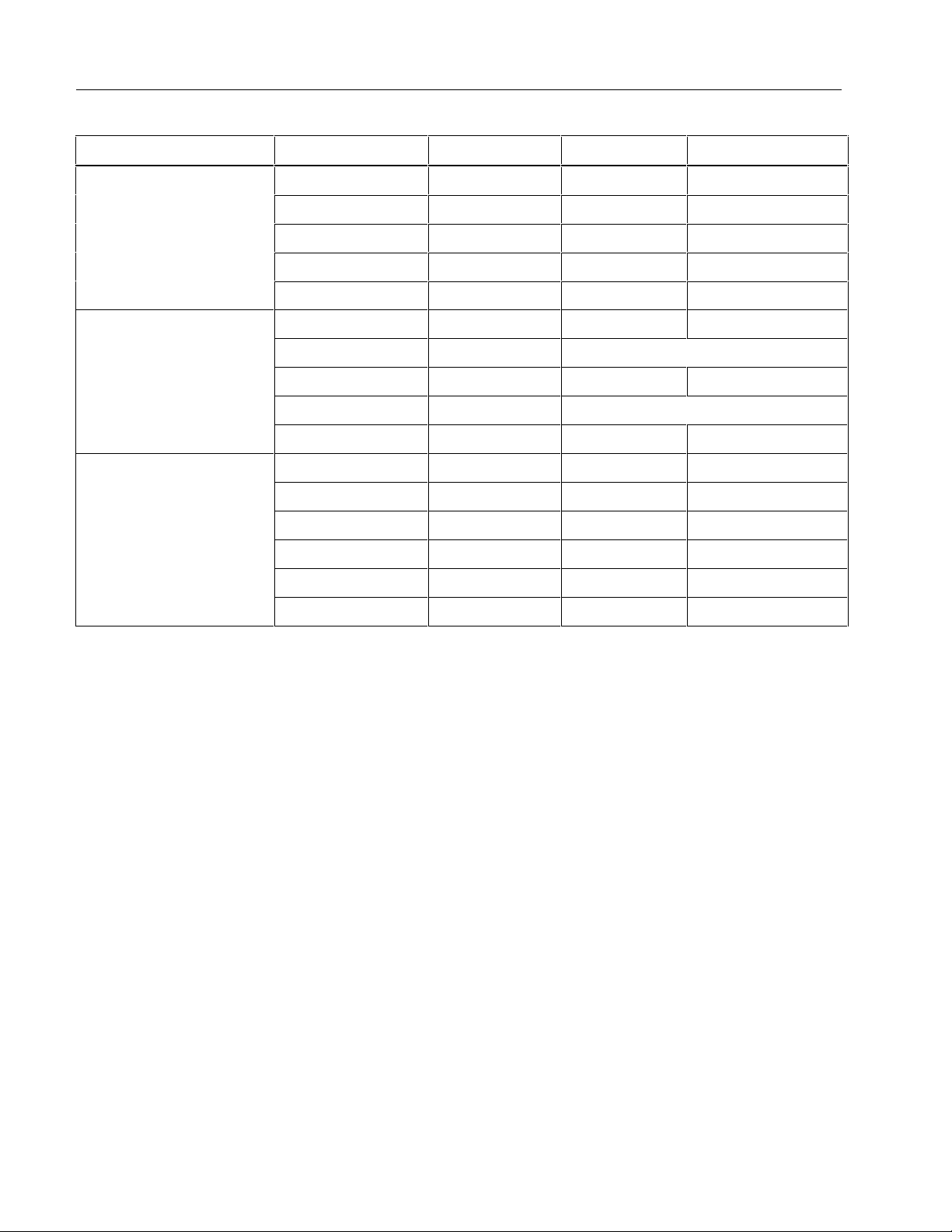
Tabel 1. Nauwkeurigheidsspecificaties
Functie Bereik Resolutie
Nauwkeurigheid
± ([% van aflezing] + [digits])
(N10140), VDE
Model
Dc-mV 600,0 mV 0,1 mV 0,5 % + 2 114, 115, 117
Dc-V
6,000 V
60,00 V
600,0 V
dc, 45 Hz tot
Auto-V LoZ
[1]
true-rms 600,0 V 0,1 V
[1]
Ac-mV
Ac-V
true-rms
[1]
true-rms
600,0 mV 0,1 mV
6,000 V
60,00 V
600,0 V
0,001 V
0,01 V
0,1 V
0,001 V
0,01 V
0,1 V
0,5 % + 2 114, 115, 117
500 Hz
500 Hz tot 1 kHz
2,0 % + 3 4,0 % + 3 114, 117
45 Hz tot 500 Hz
1,0 % + 3
1,0 % + 3
500 Hz tot 1 kHz
2,0 % + 3
2,0 % + 3
114, 115, 117
114, 115, 117
20
Page 23

True-rms Multimeters
Algemene specificaties
Tabel 1. Nauwkeurigheidsspecificaties (vervolg)
Functie Bereik Resolutie
Continuïteit 600 Ω 1 Ω
Pieptoon aan bij < 20 Ω, uit bij > 250 Ω;
detectie van open of kortgesloten
Nauwkeurigheid
± ([% van aflezing] + [digits])
stroomkringen van 500 μs of langer.
Ohm
600,0 Ω
6,000 kΩ
60,00 kΩ
600,0 kΩ
6,000 MΩ
40,00 MΩ
0,1 Ω
0,001 kΩ
0,01 kΩ
0,1 kΩ
0,001 MΩ
0,01 MΩ
0,9 % + 2
0,9 % + 1
0,9 % + 1
0,9 % + 1
0,9 % + 1
5 % + 2
Diodetest 2,000 V 0,001 V 0,9 % + 2
Capaciteit 1000 nF
LoZ-capaciteit
(opstartoptie)
10,00 μF
100,0 μF
9999 μF
1 nF
0,01 μF
0,1 μF
1 nF tot 500 μF 10 % + 2 typisch
1 μF
1,9 % + 2
1,9 % + 2
1,9 % + 2
100 μF - 1000 μF: 1,9 % + 2
> 1000 μF: 5 % + 20
Model
114, 115, 117
114, 115, 117
115, 117
115, 117
115, 117
21
Page 24

114, 115 and 117
Gebruiksaanwijzing
Tabel 1. Nauwkeurigheidsspecificaties (vervolg)
Functie Bereik Resolutie
6,000 A
Ac-A true-rms
(45 Hz tot
500 Hz)
[1]
Dc-A
Hz (V- of A-
[2]
ingang)
Opmerkingen:
[1] Alle ac-bereiken behalve Auto-V LoZ zijn gespecificeerd van 1 % tot 100 % van het bereik. Auto-V LoZ is
gespecificeerd van 0 V. Omdat ingangswaarden onder 1 % van het bereik niet zijn gespecificeerd, is het normaal
dat deze en andere true-rms-meters aflezingen anders dan nul weergeven wanneer de meetkabels van een circuit
worden losgekoppeld of met elkaar worden kortgesloten. Voor volt is de crestfactor ≤ 3 bij 4000 digits, met lineaire
afname tot 1,5 bij volle schaal. Voor A is de crestfactor ≤ 3. Ac-spanning is ac-gekoppeld. Auto-V LoZ, ac-mV en
ac-A zijn dc-gekoppeld.
[2] Ac-V Hz is ac-gekoppeld en gespecificeerd van 5 Hz tot 50 kHz. Ac-A Hz is dc-gekoppeld en gespecificeerd van
45 Hz tot 5 kHz.
[3] > 10 A niet gespecificeerd.
[3]
10,00 A
20 A gedurende maximaal
30 seconden, minimaal
10 minuten rust.
6,000 A
[3]
10,00 A
20 A gedurende maximaal
30 seconden, minimaal
10 minuten rust.
99,99 Hz
999,9 Hz
9,999 kHz
50,00 kHz
0,001 A
0,01 A
0,001 A
0,01 A
0,01 Hz
0,1 Hz
0,001 kHz
0,01 kHz
Nauwkeurigheid
± ([% van aflezing] + [digits])
1,5 % + 3
1,0 % + 3
0,1 % + 2
Model
115, 117
115, 117
115, 117
22
Page 25

True-rms Multimeters
Algemene specificaties
Tabel 2. Ingangskenmerken
Functie
V ac > 5 MΩ <100 pF > 60 dB bij dc, 50 Hz of 60 Hz
V dc
Auto-V LoZ ~3 kΩ < 500 pF > 60 dB bij dc, 50 Hz of 60 Hz
Diodetest < 2,7 V dc 2,000 V dc < 1,2 mA
Ingangsimpedantie
(nominaal)
>10 MΩ <100 pF > 100 dB bij dc, 50 Hz of 60 Hz
Nullasttestspanning Volschalige spanning Kortsluitstroom
Common mode onderdrukking
(1 kΩ ongebalanceerd)
tot 6,0 MΩ 40 MΩ Ohm < 2,7 V dc
< 0,7 V dc < 0,9 V dc
Normal mode
onderdrukking
> 60 dB bij 50 Hz of
60 Hz
< 350 μA
23
Page 26

114, 115 and 117
Gebruiksaanwijzing
24
Page 27

321 and 322
Clamp Meter
Instr
uction Card
Read the 321, 322 Clamp Meter Safety Sheet
before using this meter.
Lisez la fiche de sécurité 321, 322 Clamp Meter
Safety Sheet avant d'utiliser cet appareil.
Prima di usare questo strumento, leggere il
documento 321, 322 Clamp Meter Safety Sheet.
Vor der Verwendung des Meßgeräts die
Sicherheitsinformationen zum 321, 322, Clamp
Meter lesen
Lea la hoja de instrucciones de seguridad "321, 322
Clamp Meter Safety Sheet" antes de utilizar este
medidor.
Leia "321, 322 Clamp Meter Safety Sheet" antesde
usar este medidor.
Lees het 321, 322 Clamp Meter Safety Sheet
voordat u deze meter gebruikt
Les 321, 322 Clamp Meter Safety Sheet før
måleinstrumentet tas i bruk.
Man skal læse "321, 322 Clamp Meter Safety Sheet"
inden man tager instrumentet i brug.
Lue 321, 322 Clamp Meter Safety Sheet ennen
tämän laitteen käyttöä.
Läs säkerhetsdatabladet "321, 322 Clamp Meter
Safety Sheet" innan du använder detta instrument.
Sheet
321, 322
Safety Sheet
Safety Sheet
Safety Sheet
321, 322 Clamp Meter Safety Sheet
PN 1615194 February 2002
2001, 2002 Fluke Corporation, All rights reserved. Printed in Taiwan.
www.fluke.com
Warning
321, 322 Clamp Meter Safety
321, 322 Clamp Meter
321, 322 Clamp Meter
321, 322 Clamp Meter
On/Off
V
V
MET
A
P
OFF
HOLD
AM
L
322
C
Automatic Off
30 Min
V
A
OFF
HOLD
AM
L
C
A
Specifications
Fluke 321 0 - 400.0 A
ER
V
ER
MET
P
322
Fluke 322 0 - 40.00 A, 40.0 - 400.0 A
CAT
A
COM
CAT
600V
400A
V
ER
V
MET
A
P
OFF
HOLD
AM
L
322
C
600V MAX
V
CAT
600V
400A
V
ER
V
MET
A
P
OFF
HOLD
AM
L
322
C
600V MAX
V
COM
CAT
Currents Cancel
Les courants s'annulent, Le correnti si cancellano,
A
V
V
Ω
Continuity
Jaw Opening
IP Rating
Storage
Temperature
Range
Accuracy
AC Response
Range
Accuracy
Range
Accuracy
Range
Accuracy
0 - 400.0 A
50 - 60 Hz 1.8% 5 counts
60 Hz - 400 Hz 3.0% 5 counts
50 - 400 Hz 1.2% 5 counts
1 inch or 26 mm
0 - 40.00 A
40.0 - 400.0 A
Avg
0 - 400.0, 400 - 600 V
0 - 400.0,
400 - 600 V
1% 5 counts
0 - 400.0
1.0% 5 counts
<
30 Ω
40
3
Operating
Temperature
Altitude
2000 m
EMC - EN61326
CAT III 600V, pollution degree II:
CAT III equipment is designed to protect against transients in
equipment in fixed - equipment installations, such as distribution
panels, feeders and short branch circuits, and lighting systems
in large buildings.
< 18 C, > 28 C add 0.1 x (specified accuracy)/ C.
Ströme abbrechen, Se cancelan las corrientes,
Cancelamento de correntes, Stromen compenseren
elkaar, Strømutjevning, Strømstyrkeannullering
Strømstyrker udbalancerer, Virta pois, Avbryt ström
,
,
,,
Page 28

Continuity
CAT
CAT
Hold Battery Replacement
Cleaning
Wipe the case with a damp cloth and mild
1
detergent. Do not use abrasives or solvents.
Nettoyage : essuyer l'étui à l'aide d'un chiffon humide
600V
400A
CAT
600V
400A
et d'un détergent non-abrasif. Ne pas utiliser
d'abrasifs ou de solvents.
Pulizia : pulire l'involucro con un panno umido e un
V
V
A
OFF
HOLD
CLAMP METER
30
322
A
V
OFF
CLAMP METER
V
2
HOLD
322
AmpsAuto
AC
AAA
600V MAX
V
COM
CAT
600V MAX
V
COM
CAT
1
V
V
detergente neutro. Non usare né abrasivi né solventi.
Limpieza: Limpie la caja con un paño húmedo y un
detergente suave. No utilice abrasivos ni solventes.
Reinigung: Das Gehäuse mit einem feuchten
Lappen und mildem Reinigungsmittel abwischen.
Keine Scheuer- oder Lösungsmittel verwenden.
Limpeza: Para limpar a parte externa, use um pano
úmido com detergente neutro. Não use produtos
abrasivos nem solventes.
Reinigen: Veeg de behuizing af met een vochtige
doek en niet-agressief detergens. Gebruik geen
schuurmiddelen of oplosmiddelen.
Rengjøring: Tørk av huset med en fuktig klut og
mildt vaskemiddel. Bruk ikke skuremidler eller
løsemidler.
A
OFF
HOLD
322
600V
400A
CLAMP METER
HOLD
V,
0 - 600 V dc 322
0 - 600 V ac
2
0 - 400.0
Rengøring: Tør instrumenthuset af udenpå med en
fugtig klud og mildt sæbevand. Der må ikke benyttes
skure- og opløsningsmidler.
Puhdistaminen: Pyyhi kotelo kostealla kankaalla ja
miedolla pesuaineella. Älä käytä hankausaineita tai
liuottimia.
Rengöring: Torka av kåpan med en fuktad trasa och
ett milt rengöringsmedel. Använd inte nötande
rengöringsmedel eller lösningsmedel.
V
OFF
HOLD
CLAMP METER
600V MAX
600V
400A
V
322
V
CAT
V
V
600V
V
OFF
CLAMP METER
600V MAX
400A
V
HOLD
322
V
CAT
Amps
AC
A
OFF
HOLD
322
CLAMP METER
600V MAX
V
COM
CAT
CAT
A
COM
CAT
V
V
A
COM
3
Page 29

(German)
W
Bitte zuerst lesen: Sicherheitshinweise
Vor Betrieb und Wartung des Meßgeräts bitte di e folge nde n
Sicherheitshinweise sorgfältig lesen:
• Wenn möglich, nicht allein arbeiten, damit Hilfestellung
gewährleistet werden kann.
• Das Meßgerät nicht bei Spannungen über 600 V oder
Frequenzen über 400 Hz Grundfrequenz be nutz e n, um
Geräteschäden zu vermeiden.
• Keine Strommessungen vornehmen, solange Testleit unge n a n
den Eingangsbuchsen angeschlossen sind.
• Bei sichtbaren oder vermuteten Beschädigungen das
Meßgerät oder die Testleitunge n nic ht benutz e n.
• In der Nähe von Stromleitern und Sammelschienen äußerste
Vorsicht walten lassen, da Berührungen elektrische Schläge
verursachen können.
• Vor dem Gebrauch die Anleitungskarte durchlesen und alle
Sicherheitshinweise befolgen.
• Das Meßgerät nur wie in der Anleitungskarte beschrieben
benutzen, da sonst die Schutzvorr ic ht unge n des Gerä t s
beeinträchtigt werden können.
• Bei Gleichspannungen über 60 V und Wechselspannungen
über 30 V Vorsicht walten lassen, da derarti ge Spannunge n
eine Stromschlaggefahr darstellen.
Symbole
Die Anwendung im Bereich GEFÄHRLICHER
,
W
M
STROMFÜHRENDER Leiter sowie das Trennen von
solchen Leitern ist zulässig.
Gefahrenrisiko. Wichtige Informationen. Anleitungskarte
einsehen
Geräteschutz durch doppelte oder verstärkte Isolation
T
Batterielage
Entspricht CSA C22.2 Nr. 1010. 2.032-96
P
J
F
B
;
N10140
t
Dieses Fluke-Produkt ist für 2 Jahre ab Kaufdatum frei von Material- und
Fertigungsdefekten. Diese Garantie erstreckt sich nicht auf Sicherungen,
Einwegbatterien oder Schäden durch Unfälle, Fahrlässigkeit, Mißbrauch,
Änderungen oder abnor male Betriebsbedingu ng en bzw . uns achgemäße
Bedienung. Die Verkaufsstellen sind nicht dazu berechtigt, diese Garantie im
Namen von Fluke zu erweitern. Um die Garantieleistung in Anspruch zu
nehmen, wenden Sie sich an das nächstgelegene Fluke-Service-Center, um
Informationen zur Rücksendeautorisierung zu erhalten, und senden Sie das
Produkt anschließend mit einer Beschreibung des Problems an dieses
Service-Center.
DIESE GARANTIE IST IHR EINZIGER RECHTSANSPRUCH. KEINE
ANDEREN GARANTIEN, WIE DIE DER ZWECKDIENLICHKEIT FÜR EINEN
BESTIMMTEN EINSATZ, WERDEN AUSDRÜCKLICH ERTEILT ODER
IMPLIZIERT. FLUKE ÜBERNIMMT KEINE HAFTUNG FÜR AUS
IRGENDWELCHEN GRÜNDEN ODER RECHTSTHEORIEN
ABGELEITETEN SPEZIELLEN, MITTELBAREN, BEGLEIT- ODER
FOLGESCHÄDEN BEZIEHUNGSWEISE VERLUSTE.
Da in einigen Ländern der Ausschluß oder die Begrenzung von Begleit- oder
Folgeschäden nicht zulässig ist, kann es sein, daß die obengenannten
Haftungsbegrenzung für Sie nicht zutrifft.
Fluke Corporation
P.O. Box 9090
Everett, WA 98206-9090
U.S.A.
Übereinstimmung mit der Richtlinien der Europäischen
Union.
Erde
Gleichstrommessung
Wechselstrommessung
Entspricht den relevanten australischen Standards
Entspricht UL 3111-1 und UL 3111-2-032
Geprüft und lizenziert durch TÜV Product Services
Beschränkte Garantie & Haftungsbeschränkung
Fluke Europe B.V.
P.O. Box 1186
5602 BD Eindhoven
Niederlande
Bitte besuchen Sie www.fluke-warranty.com, um das
Produkt zu registrieren
11/99
Page 30

321, 322
Clamp Meter
Safety Sheet
(English)
W
Read First: Safety Information
To ensure safe operation and service of the meter, follow
these instructions:
• Avoid working alone so assistance can be rendered.
• Never use the meter on a circuit with voltages higher than
600 V or a frequency higher than 400 Hz fundamental. The
meter may be damaged.
• Never measure current while the test leads are inserted into
the input jacks.
• Do not use the meter or test leads if they look damaged.
• Use extreme caution when working around bare conductors
or bus bars. Contact with the conductor could result in
electric shock.
• Read the instruction card before use and follow all safety
instructions.
• Use the meter only as specified in the instruction card;
otherwise, the meter’s safety features may not protect you.
• Use caution when wo rk ing with voltages above 60 V dc or
30 V ac. Such voltages pose a shock hazard.
Symbols
,
W
M
P
J
F
B
;
N10140
t
Application around and removal from HAZARDOUS LIVE
conductors permitted.
Risk of danger. Important information. See instruction card
Equipment protected by double or reinforced insulation
T
Battery
Conforms to CSA C22.2 No 1010. 2.032-96
Conforms to EU directives
Earth
DC measurement
AC measurement
Conforms to relevant Australian standards
Conforms to UL 3111-1 and UL 3111-2-032
Inspected and licensed by TÜV Product Services
®
Limited Warranty and Limitation of Liability
This Fluke product will be free from defects in material and
workmanship for 2 years from the date of purchase. This warranty does
not cover fuses, disposable batteries, or damage from accident, neglect,
misuse, alteration, contamination, or abnormal conditions of operation
or handling. Resellers are not authorized to extend any other warranty
on Fluke’s behalf. To obtain service during the warranty period, contact
your nearest Fluke authorized service center to obtain return
authorization information, then send the product to that Service Center
with a description of the problem.
THIS WARRANTY IS YOUR ONLY REMEDY. NO OTHER
WARRANTIES, SUCH AS FITNESS FOR A PARTICULAR PURPOSE,
ARE EXPRESSED OR IMPLIED. FLUKE IS NOT LIABLE FOR ANY
SPECIAL, INDIRECT, INCIDENTAL OR CONSEQUENTIAL DAMAGES
OR LOSSES, ARISING FROM ANY CAU SE OR THEORY. Since some
states or countries do not allow the exclusion or limitation of an implied
warranty or of incidental or consequential damages, this limitation of
liability may not apply to you.
Fluke Corporation
P.O. Box 9090
Everett, WA 98206-9090
U.S.A.
To register your product, visit www.fluke-warranty.com
Fluke Europe B.V.
P.O. Box 1186
5602 BD Eindhoven
The Netherlands
11/99
Page 31

ClampMeters
Calibration Information
Introduction
WWarning
To avoid electric shock or injury, do not perform the performance tests or
calibration procedures unless you are qualified to do so.
The information provided in this manual is for the use of qualified personnel
only.
The 32X Calibration Information provides the information necessary to verify the performance and adjust
the calibration of the Fluke 321 and 322 ClampMeters, hereafter known as the Meter(s).
®
32X
The following information is included in this document:
• Safety Information and International Electrical Symbols
• Specifications
• Replacing the Batteries
• Cleaning
• Performance Tests
• Calibration Adjustment
• User-Replaceable Parts and Accessories
• Warranty Statement
See the 321,322 Instruction Card for complete operating instructions.
Contact Information
To contact Fluke, call:
1-888-99-FLUKE (1-888-993-5853) in USA
1-800-36-FLUKE (1-800-363-5853) in Canada
+31 402-675-200 in Europe
+81-3-3434-0181 Japan
+65-738-5655 Singapore
+1-425-446-5500 in other countries
For additional information about Fluke, its products, and services, visit Fluke’s web site at:
www.fluke.com
To register this product, go to register.fluke.com
PN 1631636 October 2001 Rev.1, 12/03
© 2001-2003 Fluke Corporation. All rights reserved. Printed in U.S.A.
1
Page 32

32x
Calibration Information
Safety Information
WWarnings and Precautions
To avoid possible electric shock or personal injury, and to avoid possible damage to the Meter
or the equipment under test, adhere to the following practices:
Avoid working alone so assistance can be rendered.
•
Never use the Meter on a circuit with voltages higher than 600 V or a frequency
•
higher than 400 Hz fundamental. The meter may be damaged.
Do not use the Meter or test leads if they look damaged.
•
Use extreme caution when working around bare conductors or bus bars. Contact
•
with the conductor could result in electric shock.
Read the instruction card and safety sheet before use and follow all safety instructions.
•
Use the Meter only as specified in the instruction card; otherwise, the Meter’s safety
•
features may be impaired.
Use caution when working with voltages above 60 V dc or 30 V ac. Such voltages
•
pose a shock hazard.
Before using the Meter, inspect the case. Do not use the Meter if it is damaged. Look for
•
cracks or missing plastic. Pay particular attention to the insulation around the connectors.
Verify the Meter’s operation by measuring a known voltage. Do not use the Meter if it
•
operates abnormally. Protection may be impaired. When in doubt, have the Meter serviced.
Do not apply more than the rated current or voltage, as marked on the Meter.
•
Use the proper terminals, function, and range for your measurements.
•
Do not operate the Meter with the case (or part of the case) removed.
•
When servicing the Meter, use only specified replacement parts.
•
International Electrical Symbols
The following international symbols appear in this document and on the Meter.
N10140
Risk of electric shock
Risk of danger. Important Information. See manual.
Equipment protected by double or reinforced Insulation
Battery
Conforms to CSA C22.2 No 1010. 2.032-96
Conforms to EU directives
Earth
DC measurement
AC measurement
Conforms to relevant Australian standards
Conforms to UL 3111-1 and UL 3111-2-032
Inspected and licensed by TÜV Product Services
2
Page 33

Specifications
*@ 23 °C ± 5 °C, 0 - 90% RH 321 322
ClampMeters
Specifications
?
(50/60 Hz)
Continuity R ≤ 30 Ω
Jaw Opening 1 inch (26 mm)
IP Rating 40
Storage Temperature -40 °C to 60 °C
Operating Temperature -10 °C to 50 °C
Altitude 2000 m
Range 0 - 400.0 A 0 - 40.0 A
40 .0 - 400.0 A
Accuracy 50 Hz - 60 Hz 1.8 % ± 5 counts
60 Hz - 400 Hz 3.0 % ± 5 counts
AC Response Avg
Range 0 - 400.0 V, 400 - 600 VK
Accuracy 50 Hz - 400 Hz 1.2 % ± 5 counts
Range 0 - 400.0 V, 400 - 600 VL
Accuracy
Range 0 - 400.0 Ωe
Accuracy 1.0 % ± 5 counts
_
1 % ± 5 counts
EMC- EN61326
CAT III 600 V, pollution degree II:
CAT III equipment is designed to protect against transients in equipment in fixed-equipment installations, such as
distribution panels, feeders and short branch circuits, and lighting systems in large buildings.
* < 18 °C, > 28 °C add 0.1 x (specified accuracy)/ °C
3
Page 34

32x
Calibration Information
Replacing the Batteries
To avoid false readings, that could lead to possible electric shock or personal
injury, replace the batteries as soon as the low battery indicator (
Disconnect the test leads before replacing the batteries.
To replace the batteries (refer to Figure 1):
WWarning
b ) appears.
1. Turn the rotary switch to
OFF and remove the test leads from the terminals.
2. Loosen the battery compartment door screw, and remove the door from the case bottom.
3. Remove the batteries.
4. Replace the batteries with 2 new AAA batteries.
5. Reattach the battery compartment door to the case bottom and tighten the screw.
1
2
AAA
Figure 1. Replacing the Batteries
Cleaning
W Warning
To avoid electrical shock, remove any input signals before cleaning.
Caution
To avoid damaging the Meter, do not use aromatic hydrocarbons or chlorinated
solvents for cleaning. These solutions will react with the plastics used in the
instruments.
Clean the instrument case with a damp cloth and mild detergent.
4
ade02.eps
Page 35

ClampMeters
Performance Tests
Performance Tests
WWarning
To avoid electric shock, do not perform the performance test procedures unless
the Meter is fully assembled.
The following performance tests verify the complete operation of the Meter and check the accuracy of
each meter function against the Meter’s specifications. If the Meter fails any part of the test, calibration
adjustment and/or repair is indicated.
In the performance tests, the Meter is referred to as the unit under test (UUT).
Table 1. Required Equipment
Equipment Minimum Specifications Recommended Model
AC Calibrator
50-Turn Current
Coil
DC Voltage: 0 to ±1020 V
AC Voltage: 1 mV to 1020 V, 10 Hz to 500 kHz, Sine
AC Current: 29 µA to 20.5 A, 10 Hz to 30 kHz, Sine
Ohms: 0 to 1100 MΩ
Uncertainty due to Clampmeter/ Coil Interaction: ± (0.25% of effective
output + 0.5A), for toroidal-wound current clamps, such as the Fluke
80I and 80I-1000.
± (0.50% of effective output + 0.5A), for current clamps like the Fluke
80i-kw, 80i-400, 80i-410, 80i-500, 80i-1010, Fluke 31, Fluke 33, or
equivalent.
Fluke 5520A
Fluke 5500A/Coil
Mirror
Testing the Display
Test the display by turning the Meter on while holding down the HOLD button. Check all segments for
clarity and contrast. Refer to Figure 2.
V
V
On/Off
A
OFF
HOLD
322
CLAMP METER
Figure 2. Testing the Display
ade01f.eps
5
Page 36

32x
Calibration Information
Hold Button Test
To test the HOLD button, turn the Meter on and push the hold button. Each button push will cause the
Meter to beep.
Preparing for the Performance Test
WWarning
To avoid possible electric shock or personal injury:
Do not perform the following procedures unless qualified to do so. Some
•
procedures involve the use of high voltages.
Before handling the test connections and in between tests, make sure the
•
calibrator is in standby mode (STBY).
To prepare for the performance test:
1. Make sure that you have the required equipment, see Table 1.
2. Warm up the calibrator as required by its specifications.
3. Allow the temperature of the UUT to stabilize at room temperature ( 23 °C ± 5 °C [73 °F ± 9 °F] ).
6
Page 37

ClampMeters
Performance Tests
Performance Test Procedure
To test each of the Meter’s functions and operating ranges, do the following:
1. Connect the source to the Meter’s VΩ and COM input jacks.
2. Referring to Table 2 for the 321 and Table 3 for the 322, put the Meter in the desired function and
range for each test.
3. Apply the indicated output from the 5520A Calibrator.
4. When using the amp function on the 5520A, make sure LCOMP on the 5520A is ON.
5. The reading on the Meter display should be within the low and high limits shown in the table.
6. Repeat steps 1-4 for each function and range in Table 2 or Table 3.
If the Meter fails to perform within the low-high range indicated for each test in Table 2 or Table 3, the
Meter needs to be calibrated and adjusted, or requires some repair.
50-Turn Current Coil
Conductor
5520A Calibrator
Figure 3. 32x Amps/Hz Verification Setup
CAT
600V
V
A
OFF
HOLD
CLAMP METER
COM
322
600V MAX
CAT
V
400A
ade07f.eps
7
Page 38
32x
Calibration Information
Table 2. Performance Tests 321
Functional Test 5520 output Nominal Low Limit High Limit
AC Amps
Ohms
AC Volts
0.7 A @ 50 Hz 35 A @ 50 Hz 33.8 36.2
0.7 A @ 400 Hz 35 A @ 400 Hz 33.4 36.6
6 A @ 60 Hz 300 A @ 60 Hz 294.1 305.9
7 A @ 50 Hz 350 A @ 50 Hz 343.2 356.8
7 A @ 400 Hz 350 A @ 400 Hz 339.0 361.0
30 Ohm 30 Ohms 29.2 30.8
Beeper must be on
50 Ohm 50 Ohms 49.0 51.0
Beeper must be off
350 Ohm 350 Ohms 346.0 354.0
35 V @ 50 Hz 35 V @ 50 Hz 34.0 36.0
350 V @ 60 Hz 350 V @ 60 Hz 345.3 354.7
600 V @ 60 Hz 600 V @ 60 Hz 592.3 607.7
35 V @ 400 Hz 35 V @ 400 Hz 34.0 36.0
350 V @ 400 Hz 350 V @ 400 Hz 345.3 354.7
600 V @ 400 Hz 600 V @ 400 Hz 592.3 607.7
8
Page 39

Table 3. Performance Tests 322
Functional
Test 5520A Output Nominal Low Limit High Limit
ClampMeters
Performance Tests
AC Amps
Ohms
AC Volts
0.6 A @ 60 Hz 30 A @ 60 Hz 28.9 31.1
0.07 A @ 50 Hz 3.5 A @ 50 Hz 2.9 4.1
0.7 A @ 50 Hz 35 A @ 50 Hz 33.4 36.6
0.07 A @ 400 Hz 3.5 A @ 400 Hz 2.9 4.1
0.7 A @ 400 Hz 35 A @ 400 Hz 33.4 36.6
1 A @ 50 Hz 50 A @ 50 Hz 48.6 51.4
7 A @ 50 Hz 350 A @ 50 Hz 343.2 356.8
7 A @ 400 Hz 350 A @ 400 Hz 339.0 361.0
1 A @ 400 Hz 50 A @ 400 Hz 48.0 52.0
30 Ohm 30 Ohms 29.2 30.8
Beeper must be on
50 Ohm 50 Ohms 49.0 51.0
Beeper must be off
350 Ohm 350 Ohms 346.0 354.0
35 V @ 50 Hz 35 V @ 50 Hz 34.0 36.0
350 V @ 60 Hz 350 V @ 60 Hz 345.3 354.7
DC Volts
600 V @ 60 Hz 600 V @ 60 Hz 592.3 607.7
35 V @ 400 Hz 35 V @ 400 Hz 34.0 36.0
350 V @ 400 Hz 350 V @ 400 Hz 345.3 354.7
600 V @ 400 Hz 600 V @ 400 Hz 592.3 607.7
-350 V -350V -355.8 -344.2
35 V 35V 33.9 36.1
350 V 350V 344.2 355.8
600 V 600V 590.5 609.5
9
Page 40

32x
Calibration Information
321 Calibration Adjustment
Use the following steps to adjust the calibration of the 321 (refer to Figure 4):
1. Remove the screws on the bottom of the Meter.
2. Lift off the top case.
3. Apply 600.0 V 50 Hz from the 5520A.
4. Adjust VR1 until display reads within 1.0 V.
5. Apply 4 A 50 Hz from the 5520A to the 50-turn coil. The 50-turn coil will make the meter read 200.0
A 50 Hz .
6. Adjust VR2 until the display reads within 0.5 A. A mirror will need to be used because the calibration
point cannot be seen from the top side of the meter.
7. Replace the top case.
8. Replace the case screws.
9. Verify the calibration by going through the performance test procedures.
10
Page 41

VR3
ClampMeters
Performance Tests
VR2
Figure 4. Calibration Adjustment Points (321)
VR1
ade05f.eps
11
Page 42

32x
Calibration Information
322 Calibration Adjustment
Use the following steps to adjust the calibration of the meter (refer to Figure 5):
1. Turn the meter to DC V.
2. Remove the screws on the bottom of the Meter.
3. Lift off the top case.
4. Apply 300.0 V DC from the 5520A to the Meter..
5. Adjust VR1 until the UUT (Unit Under Test) display reads within 0.1 V.
6. Change the meter to the V AC function.
7. Apply 300 V @ 60 Hz.
8. Adjust VR2 until the UUT display reads within 0.1. V.
9. Change to the A AC function.
10. Apply 6 A 60 Hz to the 50-turn coil. The 50-turn coil will cause the Meter read this as 300.0 A 60Hz.
11. Adjust VR3 until this difference between steps 8 and 11 is within 0.1 A. A mirror will need to be used
because the calibration point cannot be seen from the top side of the meter.
12. Replace top case.
13. Verify the calibration by going through the Performance Test procedures.
12
Page 43

VR2
ClampMeters
Performance Tests
Figure 5. Calibration Adjustment Points 322
VR1
ade06f.eps
13
Page 44

32x
Calibration Information
User-Replaceable Parts and Accessories
CAT
600V
V
A
OFF
HOLD
CLAMP METER
COM
600V MAX
CAT
322
V
1
400A
4
2
3
Item # Description Part No Qty
A
B
C
D
Not Shown
Not Shown
Not Shown
** Fluke accessories are available from your authorized Fluke dis t ribut or.
Battery,1.5V,0-150MA, AA Alkaline 376756 2
Battery Door 1630734 1
Battery Door Screw 1611694 1
TL75 Test Lead Set** 855705 1
321, 322 Safety Sheet
321, 322 Instruction Card
Calibration Information (this document)
1615215 1
1615194 1
1631636 1
Figure 6. User-Replaceable Parts and Accessories
ade08f.eps
14
Page 45

ClampMeters
User-Replaceable Parts and Accessories
LIMITED WARRANTY AND LI M ITATION OF LIABILIT Y
This Fluke product is warranted to be free from defects in m aterial and workmanship under normal use and service. The warranty period
is 2 years and begins on the date of shipment. Parts, product repairs, and services are warranted for 90 days. This warrant y extends only
to the original buyer or end-user customer of a Fluke authorized resel l er, and does not apply to fuses , disposable batteries, o r to any
product which, in Fluke’s opinion, has been misused, altered, negl ec ted, contaminated, or damaged by accident or abnormal conditions
of operation or handling. Fluke warrants that s of tware will operate substantially in accordanc e with its functional specif ications for 90 days
and that it has been properly recorded on non-defect i v e media. Fluke does not warrant that soft ware will be error f ree or operate without
interruption.
Fluke authorized resellers shall extend this warranty on new and unused products to end-user customers only but have no authori ty to
extend a greater or different warranty on behal f of Fluke. Warranty support i s available only if product is purchased through a Fluke
authorized sales outlet or Buyer has paid the applicable int ernational price. Fluke reserv es the right to invoice B uyer for importation costs
of repair/replacement parts when product purchased in one country i s submitted for repair in another c ountry.
Fluke’s warranty obligation is limited, at Fluke’s option, to refund of the purchase price, f ree of charge repair, or replacement of a
defective product whic h i s returned to a Fluke authorized service center within the warrant y period.
To obtain warranty service, contact your nearest Fluk e authorized service cent er t o obtain return authorization information, then send the
product to that service center, with a description of the difficulty, postage and insurance prepaid (FOB Destination). Fluke assumes no
risk for damage in transit. Following warranty repair, the product will be returned to Buyer, t rans portation prepaid (FOB Destination). If
Fluke determines that fai l ure was caused by neglect, m i suse, contamination, al teration, accident, or abnorm al condition of operation or
handling, including overvoltage failures caused by use outside the product’s s pec i fied rating, or normal wear and tear of mechanical
components, Fluke will provide an estimate of repair costs and obtain authorizat ion before commencing the work. Following repair, the
product will be returned to the Buyer transport at i on prepaid and the Buyer will be billed for the repair and return transportation charges
(FOB Shipping Point).
THIS WARRANTY IS BUYER'S SOLE AND EXCLUSIVE REMEDY AND IS IN LIEU OF ALL OTHER WARRANTIES, EXPRESS OR
IMPLIED, INCLUDI NG B UT NOT LIMITED TO ANY IMPLIED WARRANTY OF M ERCHANTABILITY OR F ITNESS FOR A PARTICULAR
PURPOSE. FLUKE SHALL NOT BE LIABLE FOR ANY SPECIAL, INDIRECT, INCIDENTAL OR CONSEQUENTIAL DAMAGES OR
LOSSES, INCLUDING LOSS OF DATA, ARISING FROM ANY CAUSE OR THEORY.
Since some countries or states do not allow limi tation of the term of an impl i ed warranty, or exclusion or li m i tation of incidental or
consequential damages, the l i mitations and exclus i ons of this warranty may not appl y to every buyer. If any provision of this Warrant y is
held invalid or unenforceable by a court or other decis ion-maker of competent jurisdiction, such holding will not affect the validity or
enforceability of any other provision.
Fluke Corporation
P.O. Box 9090
Everett, WA 98206-9090
U.S.A.
Fluke Europe B.V.
P.O. Box 1186
5602 BD Eindhoven
The Netherlands
11/99
To register this product, go to www.register.fluke.com
15
Page 46

32x
Calibration Information
16
 Loading...