

Page 1

Models 110, 111 & 112
Users Manual
True RMS Multimeters
®
November 2000 (English), Rev 1 7/01
© 2000-2001 Fluke Corporation. All rights reserved. Printed in USA
Page 2

Limited Warranty and Limitation of Liability
Each Fluke product is warranted to be free from defects in material and workmanship under normal use and service. The warranty period is three years and
begins on the date of shipment. Parts, product repairs, and services are warranted for 90 days. This warranty extends only to the original buyer or end-user
customer of a Fluke authorized reseller, and does not apply to fuses, disposable batteries, or to any product which, in Fluke’s opinion, has been misused, altered, neglected, contaminated, or damaged by accident or abnormal conditions of operation or handling. Fluke warrants that software will operate substantially
in accordance with its functional specifications for 90 days and that it has been properly recorded on non-defective media. Fluke does not warrant that software
will be error free or operate without interruption.
Fluke authorized resellers shall extend this warranty on new and unused products to end-user customers only but have no authority to extend a greater or different warranty on behalf of Fluke. Warranty support is available only if product is purchased through a Fluke authorized sales outlet or Buyer has paid the applicable international price. Fluke reserves the right to invoice Buyer for importation costs of repair/replacement parts when product purchased in one country is submitted for repair in another cou nt ry.
Fluke’s warranty obligation is limit ed, at Fluk e’s option , to refu nd of the pu rch ase pri ce, fr ee of cha rge repai r, or re pl ac em ent of a defective pro duct whic h is
returned to a Fluke authorized service center within the warranty period.
To obtain warranty service, contact your nearest Fluke authorized service center to obtain return authorization information, then send the product to that service
center, with a description of the difficulty, postage and insurance prepaid (FOB Destination). Fluke assumes no risk for damage in transit. Following warranty
repair, the product will be returned to Buyer, transportation prepaid (FOB Destination). If Fluke determines that failure was caused by neglect, misuse, contami-
nation, alteration, accident, or abnormal condition of operation or handling, including overvoltage failures caused by use outside the product’s specified rating, or
normal wear and tear of mechanical components, Fluke will provide an estimate of repair costs and obtain authorization before commencing the work. Following
repair, the product will be returned to the Buyer, transportation prepaid, and the Buyer will be billed for the repair and return transportation charges (FOB Shipping Point).
THIS WARRANTY IS BUYER'S SOLE AND EXCLUSIVE REMEDY AND IS IN LIEU OF ALL OTHER WARRANTIES, EXPRESS OR IMPLIED, INCLUDING
BUT NOT LIMITED TO ANY IMPLIED WARRANTY OF MERCHANTABILITY OR FITNESS FOR A PARTICULAR PURPOSE. FLUKE SHALL NOT BE LIABLE
FOR ANY SPECIAL, INDIRECT, INCIDENTAL OR CONSEQUENTIAL DAMAGES OR LOSSES, INCLUDING LOSS OF DATA, ARISING FROM ANY CAUSE
OR THEORY.
Since some countries or states do not allow limitation of the term of an implied warranty, or exclusion or limitation of incidental or consequential damages, the
limitations and exclusions of this warranty may not apply to every buyer. If any provision of this Warranty is held invalid or unenforceable by a court or other
decision-maker of competent jurisdiction, such holding will not affect the validity or enforceability of any other provision. 11/99
Fluke Corporation
P.O. Box 9090
Everett, WA 98206-9090
U.S.A.
Fluke Europe B.V.
P.O. Box 1186
5602 BD Eindhoven
The Netherlands
11/99
Page 3

Table of Contents
Title Page
Read Before Using the Meter: Warnings and Precautions .................................................... ii
Contacting Fluke................................................................................................................... 1
"Warning" and "Caution" Statements..................................................................................... 1
Unsafe Voltage...................................................................................................................... 1
Test Lead Alert...................................................................................................................... 1
Battery Saver ("Sleep Mode") ............................................................................................... 2
Terminals.............................................................................................................................. 2
Rotary Switch Positions.........................................................................................................2
Display.................................................................................................................................. 3
MIN MAX AVG Recording Mode ........................................................................................... 4
Display HOLD....................................................................................................................... 4
Backlight (Model 112 Only)................................................................................................... 4
Manual Ranging and Auto Ra nging....................................................................................... 5
Power-Up Options................................................................................................................. 5
Making Basic Measurements................................................................................................ 6
Measuring AC and DC Voltage........................................................................................ 6
Measuring Resistance...................................................................................................... 7
Measuring Capacitance.................................................................................................... 7
Testing for Continuity....................................................................................................... 7
Testing Diodes................................................................................................................. 8
Measuring AC or DC Current (Models 111 and 112)........................................................ 8
Measuring Frequency ...................................................................................................... 9
Using the Bar Graph .............................................................................................................9
Cleaning................................................................................................................................9
Testing the Fuse (M odels 111 and 112)................................................................................ 10
Replacing the Battery and Fuse............................................................................................ 10
Specifications........................................................................................................................ 11
i
Page 4
Models 110, 111 & 112
Users Manual
W
Read Before Using the Meter: Warnings and Precautions
To avoid possible electric shock or personal injury, follow these guidelines:
• Use the Meter only as specified in this manual or the protection provided by the Meter might be impaired.
• Do not use the Meter or test leads if they appear damaged, or if the Meter is not operating properly.
• Always use proper terminals, switc h posi ti on, a nd ra nge for meas urements.
• Verify the Meter’s operation by measuring a known voltage. If i n doubt, have the Met er serv ic e d.
• Do not apply more than the rated voltage, as marked on Meter, between terminals or between any terminal and earth ground.
• Use caution with voltages above 30 V ac rms, 42 V ac peak, or 60 V dc. These voltages pose a shock hazard.
• To avoid false readings that can lead to electric shock and injury, replace the battery as soon as the low batte ry indicator (
• Disconnect circuit power and discharge all high-voltage capacitors before testing resistance, continuity, diodes, or capacitance.
• Do not use the Meter around explosive gas or vapor.
• When using test leads or probes, keep your fingers behind the finger guards.
• Remove test leads from Meter before opening the battery door or Meter case.
Symbols
B
F
D
AC (Alternating Current)
DC (Direct Current)
AC or DC
I
P
Fuse
Conforms to European Union directives
Canadian Standards Association
N
) appears.
J
W
N
Earth ground
Important information; Refer to manual
Battery (Low battery when shown on display)
Inspected and licensed by TÜV Product Services
950 Z Listed
ii
T
t
;
N10140
Double insulated
Underwriters Laboratories, Inc.
Conforms to relevant Australian standards
Page 5

Models 110, 111 & 112
True RMS Multimeters
The Fluke Model 110, Model 111, and Model 112 are batterypowered, true-RMS multimeters (hereafter "the Meter") with a
6000-count display and a bar graph. This manual applies to all
three models. All figures show the Model 112.
The Meter measures or tests the following:
• AC / DC voltage and current
• Resistance
• Continuity
• Diodes
• Voltage and current frequency
• Capacitance
These meters meet CAT III IEC 61010-1-95 standards. The IEC
61010-1-95 safety standard defines four overvoltage categories
(CAT I to IV) based on the magnitude of danger from t rans i ent
impulses. CAT III meters are designed to protect against
transients in fixed-equi pm ent installations at t he di s tribution level.
Contacting Fluke
To contact Fluke, call:
1-888-993-5853 in USA and Canada
+31 402-678-200 in Europe
+81-3-3434-0181 in Japan
+65-738-5655 in Singapore
+1-425-446-5500 anywhere in the world
Visit Fluke’s web site at : www.fluke.com.
Register your Meter at: www.fluke-warranty.com.
"Warning" and "Caution" Statements
A "WWarning" statement identif i es hazardous conditions and
actions that could c ause bodily harm or death.
A "Caution" statement i dentifies conditions and ac tions that could
damage the Meter or the equipment under tes t.
Unsafe Voltage
To alert you to the presence of a potentially hazardous volt age,
the
Y symbol is display ed when t he Meter detects a voltage
≥ 30 V or a voltage overload (OL) condit i on.
Test Lead Alert
W
Warning
Personal injury or damage to the Meter can occur if you
attempt to make a measurement with a lead in an
incorrect terminal.
To remind you to check that the test leads are in the correc t
terminals,
switch to or from
is displayed briefly when you move the rotary
LEAd
any A position.
1
Page 6
Models 110, 111 & 112
Users Manual
Battery Saver ("Sleep Mode")
The Meter automatically ent ers "Sleep mode" and blanks the
display if the Meter i s not used for 20 minutes. To disabl e the
Sleep mode, hold down the Hz
The Sleep mode is always dis abl ed i n t he MIN MAX AVG mode.
button while turning the Meter on.
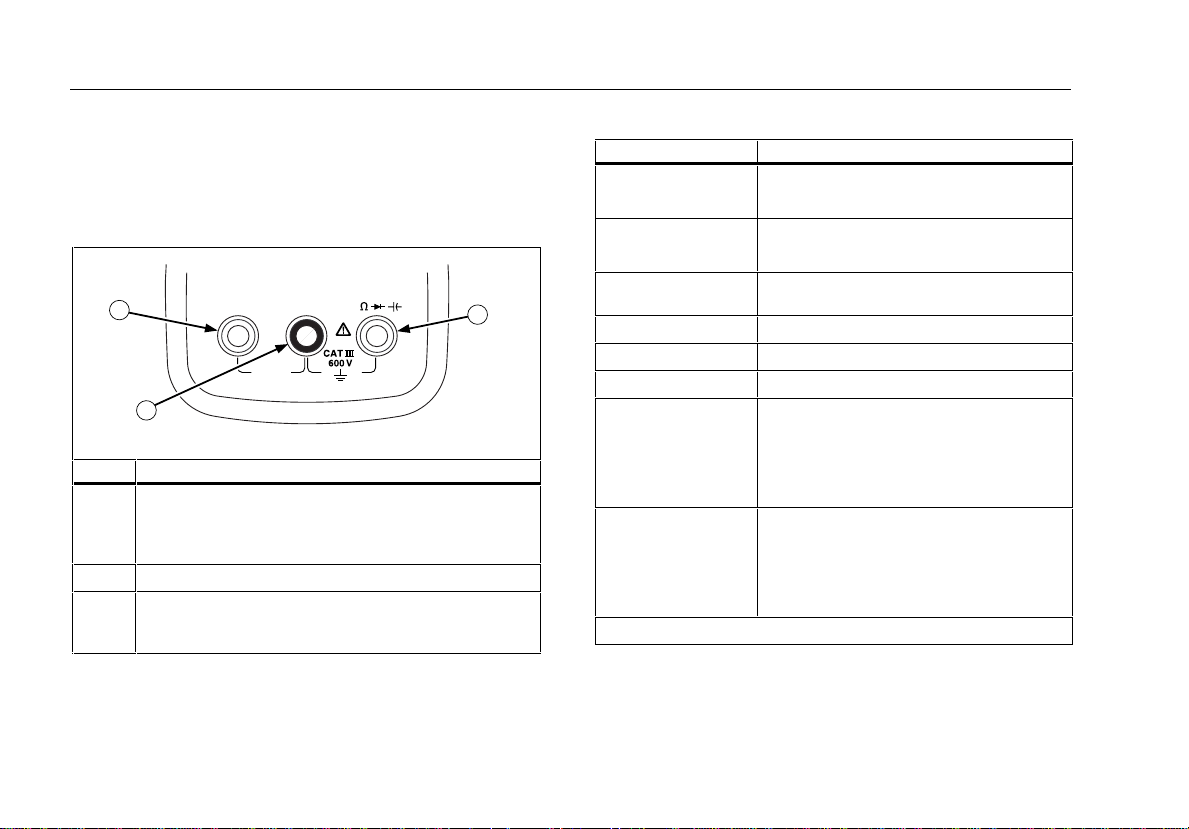
Terminals
10 A
FUSED
COMAV
3
aej01f.eps
1
2
Item Description
Input terminal for AC and DC current m easurements to
1
10 A, or to 20 A overload for 30 sec onds maximum
(Models 111 and 112 only), and for frequency of
current.
Common (return) terminal for all measurements.
2
Input terminal for volt age, continuity, resis tance, diode
3
test, capacitance, and voltage frequency
measurements.
Rotary Switch Positions
Switch Position Measurement Function
K
Hz (button)
L
Hz (button)
R
e
G
E
(Models 111 & 112)
?
Hz (button)
(Models 111 & 112)
A
Hz (button)
Notes: AC voltage and current AC-coupled, True RMS, up to 500 Hz.
AC voltage from 300 mV to 600 V .
Frequency from 5 Hz to 50 kHz.
DC voltage from 1 mV to 600 V.
Frequency from 5 Hz to 50 kHz.
Beeper turns on at < 20 Ω and turns off
at > 250 Ω.
Ohms from 0.1 Ω to 40 MΩ.
Diode test. Displays OL above 2.4 V.
Farads from 1 nF to 9999 µF.
AC current from 3 A to 10 A.
(20 A overload for 30 seconds max i m um.)
>10.00 display flashes .
>20 A, OL is displayed.
Frequency from 50 Hz to 5 kHz.
DC current from 0.001 A to 10 A.
(20 A overload for 30 seconds max i m um.)
>10.00 display flashes .
>20 A, OL is displayed.
Frequency from 50 Hz to 5 kHz.
2
Page 7
True RMS Multimeters
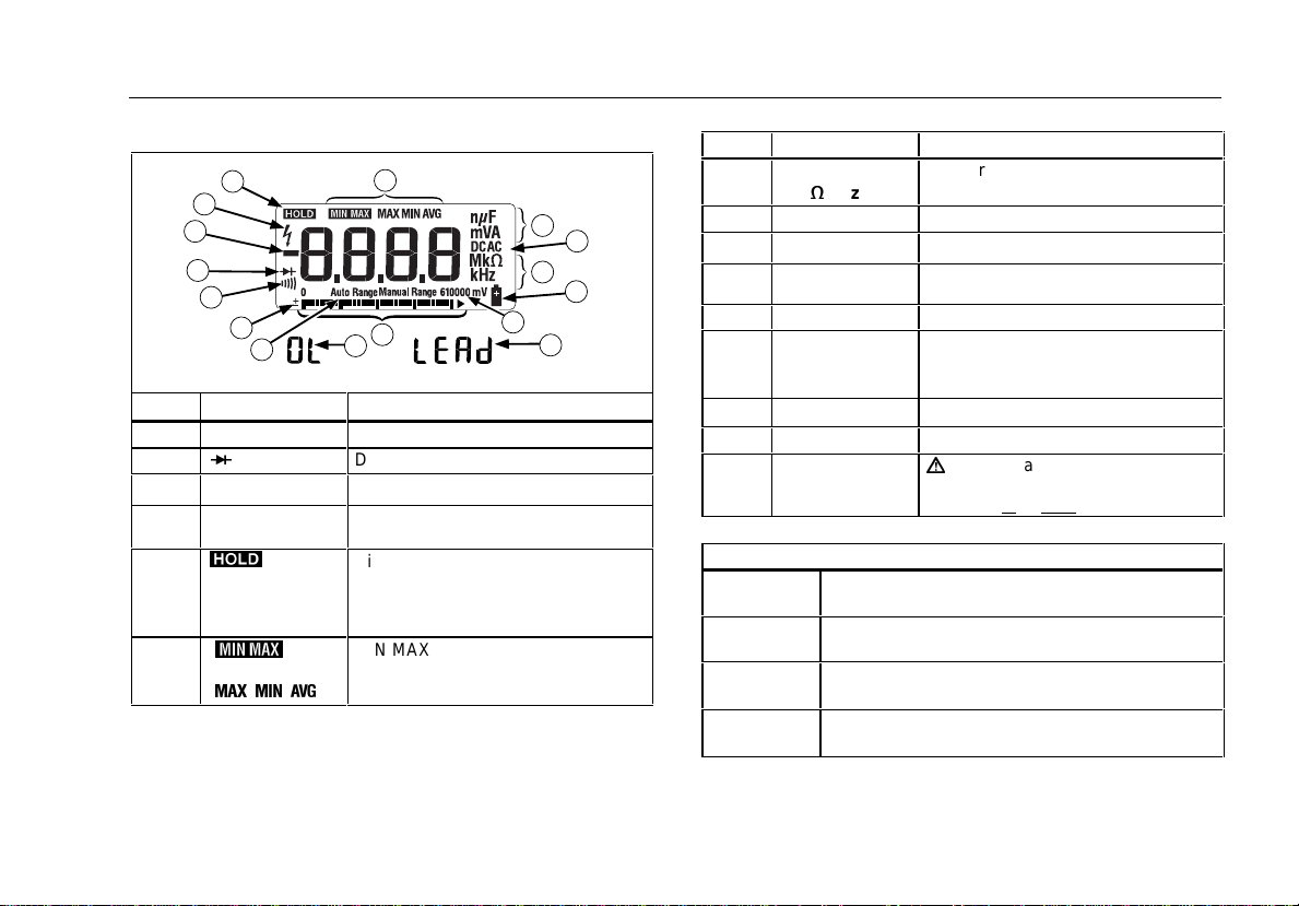
Display
Display
5
4
3
2
1
13
12
No. Symbol Meaning
1
s
2
R
3
O
4
Y
K
5
6
M
X W V
6
11
14
Meter is set to continuity function.
Diode test.
Negative readings.
Unsafe voltage. Volt age ≥ 30 V , or
voltage overload condition (OL).
Display HOLD is enabled. Di splay
freezes present reading.
In MIN MAX AVG mode, MIN MAX
AVG recording is paused.
MIN MAX AVG mode enabled.
Maximum, minimum, or average
reading displayed.
No. Symbol Meaning
7
nµF
mVA
Mk
e
kHz
8
7
8
7
9
10
15
aej02f.eps
9
10
11
12
13
14
15
DC AC
N
610000 mV
(Bar graph)
Auto Range
Manual Range
±
0L
LEAd
Measurement units.
Direct current, alternat i ng current.
Replace battery immediat el y.
All possible segment s of the range
annunciator.
Analog display.
The Meter selects the range with the
best resolution.
The user selects the range.
Bar graph polarity.
The input is too large for the range.
W
Test lead alert.
Displayed briefly when rotary switch
is moved to or from
any A position.
Error Messages
diSC
Displayed while the capaci t or di scharges. In
Capacitance function only.
EEPr
Cannot read data from EEPROM. Turn power off,
then on. If message remains, service Meter.
EEPr
Invalid EEPROM data. Have Meter serviced.
Err
CAL
Invalid calibration data. Calibrate Meter.
Err
3
Page 8
Models 110, 111 & 112
Users Manual
MIN MAX AVG Recording Mode
The MIN MAX AVG recording m ode captures the minimum and
maximum input values, and calculates a running average of al l
readings. When a new high or low is detect ed, the Meter beeps.
Put the Meter in the desired m easurement function and range.
⇒ Press MIN MAX to enter MIN MAX AVG mode.
m
detected since entering MIN MAX AVG is displ ay ed.
⇒ Press MIN MAX to step through the low (MIN), average
(AVG), and present readings.
⇒ To pause MIN MAX AVG rec ordi ng wi t hout erasing stored
values, press HOLD.
⇒ To resume MIN MAX AVG recording, press HOLD again.
⇒ To exit and erase stored readings, press MIN MAX for at leas t
one second or turn the rotary swit ch.
and MAX are displayed and the highest readi ng
h
is displayed.
Display HOLD
W
Warning
To avoid electric shock, when Display HOLD is
activated, be aware that the display will not change
when you apply a different voltage.
In the Display HOLD mode, the M eter freezes the display.
⇒ Press HOLD to activate Display HOLD. (
⇒ To exit and return to normal operation, press HOLD or turn the
rotary switch.
h
is displayed.)
Backlight (Model 112 Only)
Press S to toggle the backlight on and off. The backlight
automatically turns off after 2 minutes.
To disable the automatic 2-m i nut e backlight timeout, hold down
the S button while turning the Meter on.
4
Page 9

True RMS Multimeters
Manual Ranging and Auto Ranging
Manual Ranging and Auto Ranging
The Meter has both Manual Range and Auto Range modes .
⇒ In the Auto Range mode, the Met er s el ects the range with the
best resolution.
⇒ In the Manual Range mode, you override A uto Range and
select the range yourself .
When you turn the Meter on, it def aul t s to Auto Range and Auto
Range is displayed.
1. To enter the Manual Range mode, press RANGE. Manual
Range is displayed.
2. In the Manual Range mode, press RANGE to increment the
range. After the highest range, the Meter wraps to the lowest
range.
Note
You cannot manually change the range i n the
MIN MAX AVG or Display HOLD modes.
If you press
Hold, the Meter beeps, indic ating an invalid operation, and
the range does not change.
3. To exit Manual Range, press RANGE for at least 1 sec ond or
turn the rotary switch.
The Meter returns to Auto Range and Auto Ran g e is
displayed.
RANGE
while in MIN MAX AVG or Display
Power-Up Options
To select a Power-Up Option, hold down the button indicated for
at least 1 second while turni ng the Meter on.
Power-Up Options are canceled when you t urn the Meter off.
Button Power-Up Options
HOLD
MIN MAX
Hz
S
Turns on all display segment s.
Release HOLD to continue; the s oftware version
number is displayed briefly and the Meter resumes
normal operation.
Disables beeper.
Disables automatic power-down (" S l eep mode").
Disables automatic 2-m i nute backlight timeout.
(Model 112 Only)
5
Page 10
Models 110, 111 & 112
Users Manual
Making Basic Measurements
The figures on the following pages s how how to make basic
measurements.
When connecting the test l eads to the circuit or devic e, connect
the common (COM) test lead bef ore connecting the live lead;
when removing the test leads, remove the live lead before
removing the common test lead.
W
Warning
To avoid electric shock, injury, or damage to the Meter,
disconnect circuit power and discharge all high-voltage
capacitors before testing resistance, continuity, diodes,
or capacitance.
Note
In reading AC voltage or current, for the integrated RMS
converter to correctly measure distorted waveform s, reading
settling time inc reas es to several seconds at t he l ow end of
AC voltage and current ranges.
The Meter is not specif i ed f or use with current clamp
accessories.
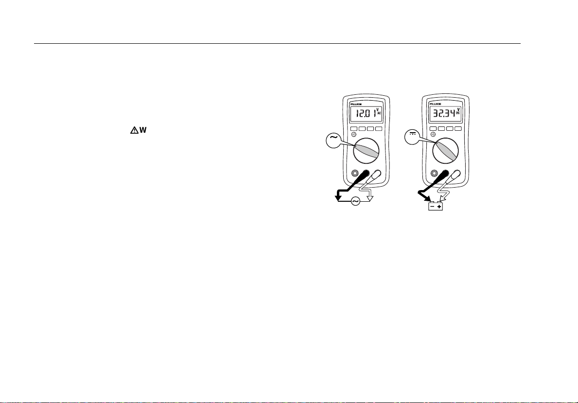
Measuring AC and DC Voltage
V
Volts DC Volts AC
V
aej03f.eps
6
Page 11

True RMS Multimeters
Making Basic Measurements
Measuring Resistance
Measuring Capacitance
aej04f.eps
Testing for Continuity
Note
The continuity funct i on works best as a fast, convenient
method to check for opens and shorts. For maximum
accuracy in making res i stance measurements, us e the
(e)
Meter’s resistance
function.
aej06f.eps
aej05f.eps
7
Page 12
Models 110, 111 & 112
Users Manual
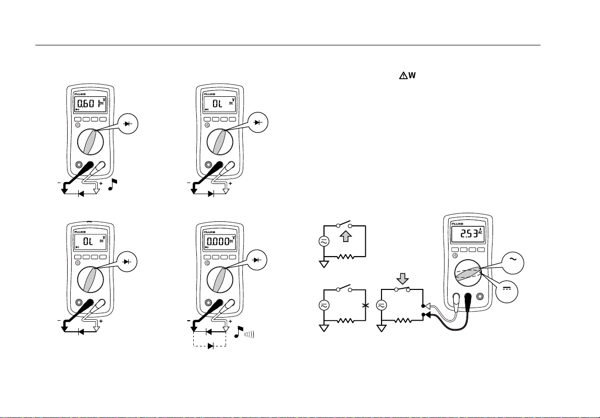
Testing Diodes
Good Diode Good Diode
Forward Bias
Bad Diode
Open
Single Beep
Reverse Bias
Bad Diode
and
Shorted
aej07f.eps
Measuring AC or DC Current (Models 111 and 112)
W
Warning
To avoid personal injury or damage to the Meter:
• Never attempt to make an in-circuit current measure-
ment when the open-circuit potential to earth is
> 600 V.
• Check the Meter's fuse before testing. (See “Testing
the Fuse”)
• Use the proper terminals, switch position, and range
for your measurement.
• Never place the probes in parallel with a circuit or
component when the leads are plugged into the
current terminals.
Turn power OFF, break circuit, insert Meter in series, turn
power on.
A
A
aej08f.eps
8
Page 13

True RMS Multimeters
Using the Bar Graph
Measuring Frequency
W
Warning
To avoid electrical shock, disregard the bar graph for
frequencies > 500 Hz. If the frequency of the measured
signal is > 500 Hz, the bar graph is unspecified.
The Meter measures the frequency of a signal by counting the
number of times the signal crosses a trigger level each s econd.
The trigger level is 0 V, 0 A f or al l ranges.
AC/DC Voltage Frequency AC/DC Current Frequency
Hz
V
Hz
V
Hz
Hz
A
A
Hz
aej09f.eps
Hz
⇒ Press Hz to turn the frequency measurement function on and
off.
⇒ In frequency, the bar graph and range annunciat or i ndi cate
the AC or DC voltage or current present .
⇒ Select progressively lower ranges using manual ranging for a
stable reading.
Using the Bar Graph
The bar graph is like the needle on an analog meter. It has an
overload indicator (>) to the right and a polarity indicator (±) to
the left.
Because the bar graph updates about 40 ti mes per second, which
is ten times faster than the digital display, the bar graph is useful
for making peak and null adjust m ents.
The bar graph is disabled when measuring capac i tance. In
frequency, the bar graph and range annunciator i ndi cate the
underlying voltage or current.
The number of segments indicates the measured value and is
relative to the full-s cale value of the selected range, except on the
10 A ranges
.
In the 60 V range, for example (s ee bel ow), the major divisions on
the scale represent 0, 30, and 60 V . An input of −30 V turns on
the negative sign and the segments up to the middle of the scale.
aej11f.eps
Cleaning
Wipe the case with a damp clot h and mild detergent. Do not use
abrasives or solvents . Dirt or moisture in the termi nal s can affect
readings.
9
Page 14
Models 110, 111 & 112
Users Manual
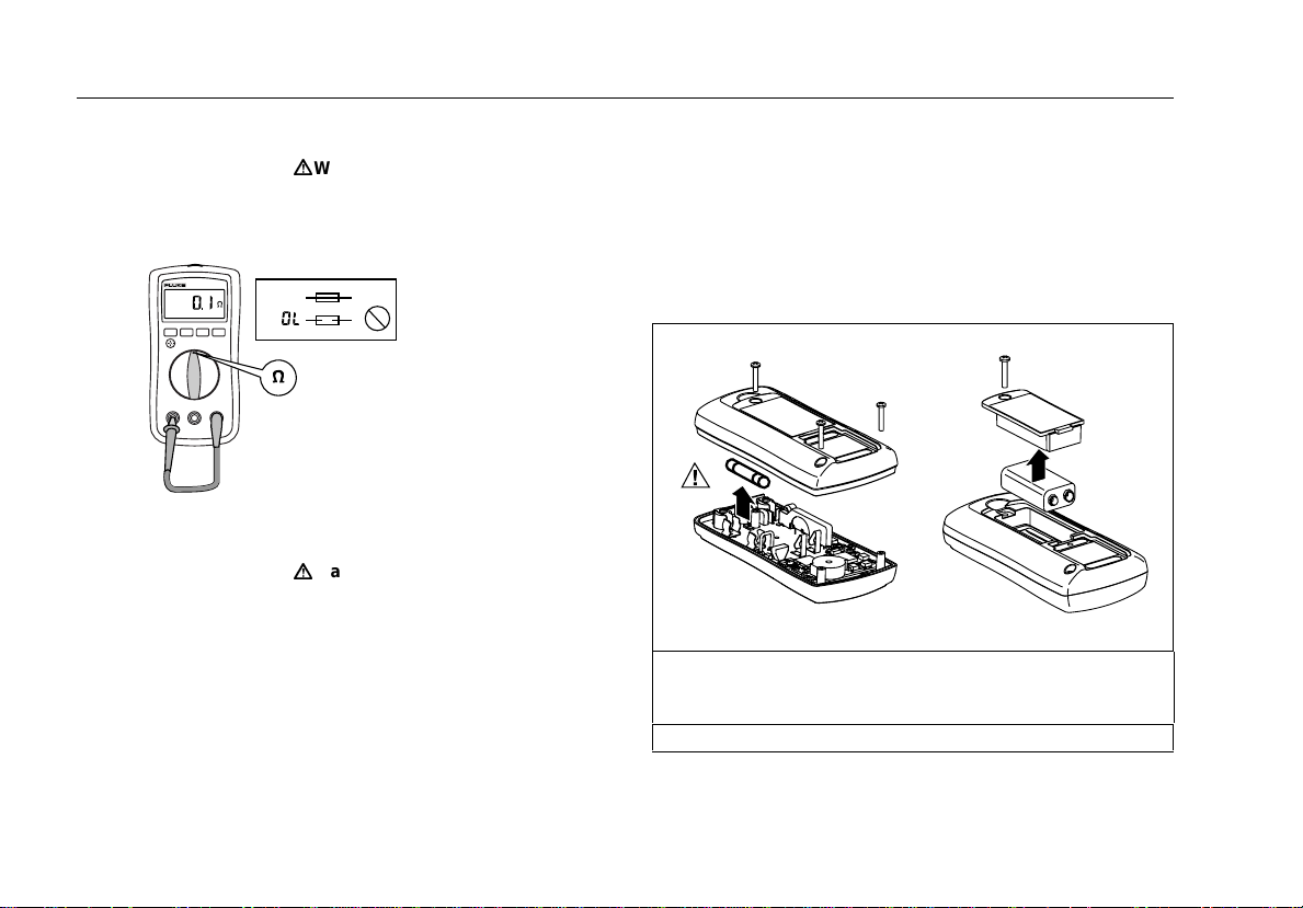
Testing the Fuse (Models 111 and 112)
W
Warning
To avoid electrical shock or injury, rem o ve the test
leads and any input signals before replacing the fuse.
Test fuse as shown below.
<.5
Ω
OK
OK
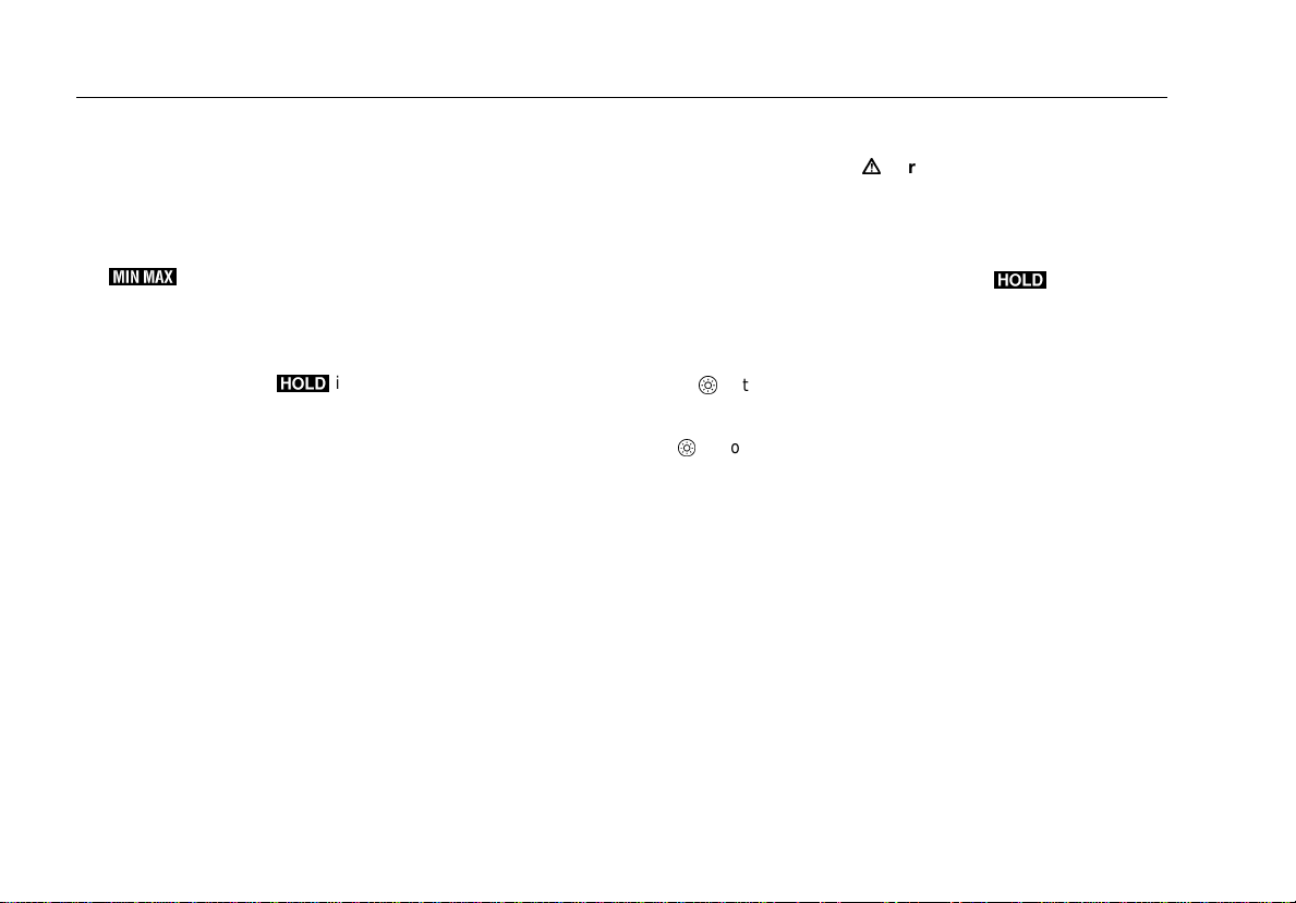
Replacing the Battery and Fuse
W
Warning
To avoid shock, injury, or damage to the Meter:
• Remove test leads from the Meter before opening the
case or battery door.
• Use ONLY a fuse with the amperage, interrupt,
voltage, and speed ratings specified.
• Replace the battery as soon as the low battery
indicator (
b ) appears to avoid false readings.
To remove the battery door:
1. Remove screw from battery door.
2. Use the finger recess to l i ft door slightly.
3. Pull door toward bottom of Met er to release the latch.
4. Lift the door straight up t o s eparate from case.
The battery fits ins i de the battery door, which is then i nserted
straight into the case until it clicks into place. Do not attempt to
install the battery di rectly into the case.
Fuse Battery
aej12f.eps
aej13f.eps
F1 Fuse (Models 111 and 112). 11 A, 1000 V, FA ST.
Minimum Interrupt Rating 17000 A .
Use only Fluke Part Number 803293.
Battery, 9 V Al kaline, NEDA 1604A / IE C 6LR61
10
Page 15
True RMS Multimeters
Specifications
Accuracy is specified for 1 year aft er c alibrat ion, at operat ing t emperatures of 18 °C to 28 °C, with relative humidity at 0 % to 95 %.
Maximum voltage between any terminal and earth ground: 600 V
Surge Protection 6 kV peak per I EC 61010-1-95
W
Fuse for A input: 11 A, 1000 V FAST Fuse
Display: Digital: 6,000 counts, updates 4/sec
Temperature: Operating: −10 °C to +50 °C
Temperature Coefficient: 0.1 x (specified accuracy) / °C for < 18 °C or > 28 °C
Electromagnetic Compatibility: Performance ≥ 3 V/m is not specified.
Relative Humidity: Noncondensing < 10 °C
Battery Life: Alkaline: 300 hours typical, without backlight
Size, with Holster (H x W x L): 4.6 cm x 9.6 cm x 16.0 cm
Weight: 350 g
Safety Compliances: ANSI/ISA-S82.01-1988, CSA C22.2 No 231 and IEC 61010-1-95 Overvoltage Category III
Certifications:
The accuracy specifications take t he f orm of: ± ( [ % of Reading ] + [ Counts ] )
Bar Graph: 33 segments, updates 40/sec
Frequency: 9,999 counts
Capacitance: 9,999 counts
Storage:−30 °C to +60 °C
0 % to 95 % @ 10 °C to 30 °C
0 % to 75 % @ 30 °C to 40 °C
0 % to 45 % @ 40 °C to 50 °C
(CAT III), 600 V
P
UL (3111),
, CSA, TÜV,
;
N10140)
(
Specifications
11
Page 16

Models 110, 111 & 112
Users Manual
Accuracy ± ( [ % of Reading ] + [ Counts ] )
Function Range Resolution Model 110 Model 111 Model 112
1,2
AC Volts
(50 Hz to 500 Hz)
-- True RMS
6000 mV
6.000 V
60.00 V
600.0 V
DC Volts 6000 mV
6.000 V
60.00 V
600.0 V
Continuity 600 Ω 1 Ω Beeper guaranteed on < 20 Ω, guaranteed off > 250 Ω; detects
Ohms 600. 0 Ω
6.000 kΩ
60.00 kΩ
600.0 kΩ
6.000 MΩ
40.00 MΩ
Diode test 2.200 V 0.001 V 0.9 % + 2
Capacitance
4
1000 nF
10.00 µF
100.0 µF
3
3
1 mV
0.001 V
0.01 V
0.1 V
1 mV
0.001 V
1.0 % + 3 1.0 % + 3 1.0 % + 3
0.7 % + 2 0.7 % + 2 0.7 % + 2
0.01 V
0.1 V
opens or shorts of 250 µs or longer.
0.1 Ω
0.001 kΩ
0.01 kΩ
0.1 kΩ
0.001 MΩ
0.01 MΩ
1 nF
0.01 µF
0.1 µF
0.9 % + 2
0.9 % + 1
0.9 % + 1
0.9 % + 1
0.9 % + 1
1.5 % + 3
1.9 % + 2
1.9 % + 2
1.9 % + 2
0.9 % + 2
0.9 % + 1
0.9 % + 1
0.9 % + 1
0.9 % + 1
1.5 % + 3
1.9 % + 2
1.9 % + 2
1.9 % + 2
0.9 % + 2
0.9 % + 1
0.9 % + 1
0.9 % + 1
0.9 % + 1
1.5 % + 3
1.9 % + 2
1.9 % + 2
1.9 % + 2
AC Amps5 -- True RMS
(50 Hz to 500 Hz)
(Models 111 and 112)
12
10000 µF
10.00 A continuous or
20 A overload for 30
seconds maximum
1 µF
100 µF - 1000 µF: 1.9% + 2
> 1000 µF: 10% + 90 typical
0.01 A NA 1.5 % + 3 1.5 % + 3
Page 17

True RMS Multimeters
Specifications
Accuracy ± ( [ % of Reading ] + [ Counts ] )
Function Range Resolution Model 110 Model 111 Model 112
DC Amps
(Models 111 and 112)
Hz6 (V or A input ) 99.99 Hz
MIN MAX AVG Accuracy
and Response Time
1. AC voltage ranges are specified from 5% of range to 100% of range.
2. Crest factor of ≤ 3 at full scale up to 300 V, decreasing linearly to crest factor ≤ 1.5 at 600 V.
3. The 6000 mV range can only be entered in Manual Range mode.
4. For film capacitors.
5. Crest factor of ≤ 3. AC current is not specified below 3A.
6. Hz is specified from 5 Hz to 50 kHz in volts, from 50 Hz to 5 kHz in amps.
Function Input Impedance (Nominal) Common Mode Rejection Ratio Normal Mode Rejection
Volts AC > 5 MΩ < 100 pF > 60 dB at DC, 50 Hz or 60 Hz
Volts DC > 10 MΩ < 100 pF > 100 dB at DC, 50 Hz or 60 Hz > 50 dB at 50 Hz or 60 Hz
Open Circuit Test Voltage To 6 MΩ 40 MΩ Short Circuit Current
Ohms
Diode test
6.000 A
10.00 A continuous or
20 A overload for 30
seconds maximum
999.9 Hz
9.999 kHz
50.00 kHz
Accuracy is the specified accurac y of t he measurement f unc t ion ± 12 digit s f or c hanges >275 ms in durat ion
(± 40 digits in AC). Typical response time: 100 ms to 80 % of signal, ex c ept V AC and A AC.
< 1.5 V DC < 600 mV DC < 1.5V DC < 500 µA
2.4 to 3.0 V DC 2.400 V DC 1.2 mA typical
0.001 A
0.01 A
0.01 Hz
0.1 Hz
0.001 kHz
0.01 kHz
NA 1.0 % + 3 1.0 % + 3
0.1 % + 2 0.1 % + 2 0.1 % + 2
Full Scale Voltage
13
Page 18

Models 110, 111 & 112
Users Manual
\
14
 Loading...