

Page 1

10100AT
TRIAD™ TnT Field Service Kit
August 2006
Manual No. 38651-1 Rev. 1
©2006 Fluke Corporation, All rights reserved. Printed in U.S.A.
All product names are trademarks of their respective companies
Operators Manual
Page 2

Fluke Biomedical
Radiation Management Services
6045 Cochran Road
Cleveland, Ohio 44139
440.498.2564
www.flukebiomedical.com/rms
Page 3

Table of Contents
Section 1: General Information ...................................................................... 1-1
1.1 Introduction.................................................................................................. 1-1
1.2 Features....................................................................................................... 1-1
1.3 Manual Addenda.......................................................................................... 1-2
1.4 Before You Start – Safety Precautions ........................................................ 1-2
1.5 Safety Symbols and Terms.......................................................................... 1-2
1.6 Specifications............................................................................................... 1-3
1.7 Unpacking and Inspection............................................................................ 1-8
1.8 Getting Started............................................................................................. 1-9
Section 2: Operation..................................................................................... 2-1
2.1 Introduction.................................................................................................. 2-1
2.2 Front Panel Familiarization.......................................................................... 2-1
2.2.1 Control Buttons....................................................................................... 2-2
2.2.2 Display.................................................................................................... 2-3
2.3 Connector Familiarization............................................................................ 2-3
2.3.1 Ion Chamber Connector......................................................................... 2-4
2.3.2 kVp Divider Connectors.......................................................................... 2-4
2.4 Power-Up Self-Test and Display Messages................................................. 2-4
2.5 Using the Options Button............................................................................. 2-5
2.6 Basic Measurement Techniques.................................................................. 2-6
2.6.1 General Considerations.......................................................................... 2-6
2.6.2 Making Exposure Measurements........................................................... 2-9
2.6.3 Making Exposure Rate Measurements................................................... 2-9
2.6.4 Use of the Model 35050AT Dosimeter as a kVp Divider Readout........ 2-10
2.7 Simultaneous Measurement Mode............................................................ 2-13
2.7.1 Making Combined Exposure Rate and kVp Measurements ................. 2-13
2.7.2 Making Combined Exposure, kVp, and Time Measurements............... 2-13
2.7.2.1 Advanced Measurements Options .................................................. 2-14
2.7.2.2 Time Corrections............................................................................. 2-14
2.7.3 Making kVp and Time Measurements Without an Ion Chamber .......... 2-14
2.7.4 Making Exposure or Exposure Rate Measurements Without a Model
35080/80A/80B kVp Divider ................................................................. 2-15
2.7.4.1 Advanced Measurements Options .................................................. 2-15
2.8 Exclusive Measurement Mode................................................................... 2-16
2.9 Using the Ion Chamber Test Stand and Accessories ................................ 2-17
2.9.1 Using the Test Stand for Over-Table Tubes......................................... 2-18
2.9.2 Using the Test Stand for Under-Table Tubes....................................... 2-19
i
Page 4

2.9.3 Using the Test Stand for Horizontal X-ray Beams................................ 2-21
2.9.4 Using the Test Stand for Mammo kVp Measurements......................... 2-21
2.10 Using the Ion Chamber Cable Stem .......................................................... 2-22
2.11 Measurement Considerations.................................................................... 2-22
2.11.1 Using Other Ion Chambers................................................................... 2-22
2.11.2 Using Air Density Corrections............................................................... 2-22
2.11.3 Using Exposure/Frame Units................................................................ 2-23
2.11.4 Making Mammo kVp Measurements.................................................... 2-24
2.11.4.1 Cadmium k-edge Filter Pack Use.................................................... 2-24
2.11.4.2 Linear Filter Pack Use..................................................................... 2-25
Section 3: Theory of Operation ...................................................................... 3-1
3.1 Introduction.................................................................................................. 3-1
3.2 Overall Functional Description..................................................................... 3-1
3.3 Power Supply............................................................................................... 3-2
3.4 Front Panel Switches................................................................................... 3-3
3.5 Microcomputer............................................................................................. 3-3
3.6 Display......................................................................................................... 3-3
3.7 Serial Communications Port ........................................................................ 3-3
3.8 Multiplexer/A-D Converter............................................................................ 3-4
3.9 kVp Input Signal Buffer/Divider.................................................................... 3-4
3.10 Ion Chambers.............................................................................................. 3-4
3.10.1 Basic Theory .......................................................................................... 3-4
3.10.2 Air Density Corrections........................................................................... 3-5
3.11 Electrometer/HV Isolator/Ranging Amplifier................................................. 3-5
3.12 300 Volt Electronic Bias Supply................................................................... 3-6
3-13 Measurement Technique............................................................................. 3-6
3.13.1 High Sensitivity Dose.............................................................................. 3-6
3.13.2 High Sensitivity Rate .............................................................................. 3-7
3.13.2.1 Very Low Dose Rate ......................................................................... 3-7
3.13.3 kVp/Dose/Time....................................................................................... 3-7
3.13.4 kVp/Rate................................................................................................. 3-7
3.14 Temperature and Pressure Sensor.............................................................. 3-8
Section 4:
Maintenance................................................................................. 4-1
4.1 Introduction.................................................................................................. 4-1
4.2 Cleaning the Instrument............................................................................... 4-1
4.3 Battery Replacement ................................................................................... 4-1
4.4 Fuse Replacement....................................................................................... 4-2
4.5 Replaceable Parts Information..................................................................... 4-3
4.6 Temperature / Pressure Sensor Adjustment................................................ 4-3
4.7 Recalibration and Repair Information/Technical Assistance........................ 4-4
4.8 Warranty Information ................................................................................... 4-4
ii
Page 5

Appendix A: Model 35050AT Default Ion Chamber Selection Screens...................A-1
A.1 Introduction..................................................................................................A-1
A.2 Model 96020C (150 CC) Ion Chamber ........................................................A-1
A.3 Model 96035B (15 cc) Ion Chamber............................................................A-2
Appendix B: Model 96020C Ion Chamber Specifications......................................B-1
B.1 Introduction..................................................................................................B-1
B.2 Physical Specifications ................................................................................B-1
B.3 Electrical Specifications...............................................................................B-2
B.4 Radiological Specifications..........................................................................B-2
B.5 Calibration and Verification..........................................................................B-3
B.6 Energy Correction Factors...........................................................................B-5
B.6.1 Attenuated Beam (Behind the Phantom)................................................B-5
B.6.2 Unattenuated Beam (In Front of the Phantom).......................................B-7
Appendix C: Model 96035B Ion Chamber Specification .......................................C-1
C.1 Introduction..................................................................................................C-1
C.2 Physical Specifications ................................................................................C-1
C.3 Electrical Specifications...............................................................................C-2
C.4 Radiological Specifications..........................................................................C-2
C.5 Calibration and Verification..........................................................................C-4
C.6 Energy Correction Factors...........................................................................C-5
C.6.1 Diagnostic – Unattenuated Beam (In Front of the Phantom)..................C-5
C.6.2 Diagnostic – Attenuated Beam (Behind the Phantom)...........................C-7
C.6.3 Mammographic Beam Qualities .............................................................C-8
iii
Page 6

(Blank page)
Page 7

General Information
Introduction
1
Section 1
General Information
1.1 Introduction
The TRIAD Service Kit can be used for government compliance testing, troubleshooting, repair of
diagnostic x-ray equipment, installation and setup of new equipment, preventive maintenance,
radiographic quality assurance measurements, and measurements required for JCAHO accreditation.
The TRIAD Service Kit performs measurements on all modalities: mammographic, cine, dental,
radiographic, fluoroscopic, CT, and image intensifiers.
The Model 35050AT Dosimeter, as featured in the Model 10100AT TRIAD Field Service Kit, is both a
sensitive, full-function dosimeter and a digital display for the Models 35080/80A/80B Non-invasive kVp
Divider. It features a direct readout and simplified operator controls.
This manual contains all the information necessary for you to operate and service your Model 35050AT
Dosimeter/kVp/Time Readout and the Model 10100AT TRIAD Field Service Kit components. This
manual contains a description of usage of the Model 35080/80A/80B kVp Divider with the Model 35050AT
Dosimeter as its readout. The operator is referred to the Model 35080/80A/80B kVp Divider Instruction
Manual, though, for a complete coverage of specifications, general use, etc.
Some service kits may include a Model 35035 mA/mAs meter. The user is referred to its instruction
manual for details of operation, specifications, and servicing.
Information on customizing the Model 35050AT Dosimeter using the Customization Software is contained
in a separate manual (Model 35050A Customization Instruction Manual). Also, a separate Model 35050A
Programmer's Instruction Manual contains a description of the protocol and commands used to operate
the Model 35050AT Dosimeter via the RS-232 interface. The RS-232 interface also allows the user to
capture kV waveforms obtained during simultaneous use of the Model 35050AT Dosimeter and the Model
35080/80A/80B kVp Divider. Refer to these instruction manuals as needed.
1.2 Features
Simplified Controls – automatic or manual exposure reset, autoranging, automatic offset and drift
compensation, and automatic power down.
Battery or Line Current Operation - 6 AA alkaline batteries provide instrument power with an auto
power-down feature to extend battery life and a 300 V electronic ion chamber bias. An AC adapter is
provided which allows line current operation.
Direct Reading - readout in user-selected units: R, Gy, Sv, C/kg, A, C, /s, /min, /hr, /frame; pressure and
temperature corrected readings. Temperature and pressure corrections may be made automatically using
an internal temperature and pressure sensor or by manual entry.
Ion Chamber Flexibility - radiation units for any triaxial-BNC ion chamber with a known calibration factor,
including CT ion chambers.
High Sensitivity -image intensifier measurements at 0.1 mR and 5 mR/min resolutions.
kVp+Dose+Time - kVp, dose, and exposure time measurements when used with the Model
35080/80A/80B Non-Invasive kVp Divider. Exposure time may be displayed in seconds or pulses (for
single phase or pulsed outputs).
1-1
Page 8
10100AT
Operators Manual
RS-232 Interface - remote operation, waveform capture, digital calibration, custom display units,
customer specified ion chamber calibration factors, and Model 35080/80A/80B kVp Divider filter packs.
Self-Checking - the Model 35050AT Dosimeter and Model 35080/80A/80B kVp Divider battery voltage
level, bias voltage level, ion chamber/cable leakage, and hardware/software checks.
1.3 Manual Addenda
Any improvements or changes concerning the instrument or manual will be explained in an addenda
included with the manual. Be sure to note these changes and incorporate them into the manual.
1.4 Before You Start - Safety Precautions
This instrument is intended for use by qualified personnel who recognize radiation hazards associated
with use of x-ray equipment.
Always turn off unit prior to connecting or disconnecting ion chamber or triaxial cable. Failure to do so
could result in electrical shock or damage to the equipment.
Beyond the battery and fuse, this unit contains no operator serviceable parts. The operator should not
attempt to gain access beyond the battery access cover. High voltage is generated internally and may
remain on internal parts even after the batteries have been removed.
1.5 Safety Symbols and Terms
The following symbols and terms are found on the instrument and used in this manual.
The
located in the manual.
The
standard safety precautions to avoid personal contact with these voltages.
The heading used in this manual explains dangers that might result in personal injury or
death. Always read the associated information very carefully before performing the indicated procedure.
The heading used in this manual explains hazards that could damage the instrument.
Such damage may invalidate the warranty.
symbol on the instrument indicates that the user should refer to the operating instructions
symbol on the instrument shows that high voltage may be present on the terminal(s). Use
WARNING
CAUTION
1-2
Page 9

General Information
Specifications
1.6 Specifications
Exposure and Exposure Rate Accuracy
The basic accuracy of the Model 35050AT Dosimeter is ± 1% of reading ± 2 range resolution steps (see
Table 1-1) over the range of 18 to 28° C and ± 2% of reading ± 2 range resolution steps over the full
operating temperature range of 0 to 50° C. This accuracy is guaranteed for a period of 1 year and is
exclusive of all ion chamber effects. A 3% NIST traceable calibration is provided with each system and
includes the effects of the Model 35050AT Dosimeter, Model 96035B Ion Chamber, and Model 96020C
Ion Chamber.
Temperature and Pressure Accuracy
Temperature Accuracy: ± 2°C (3.6°F)
Pressure Accuracy: ± 5mm Hg
1
NOTE
The measured temperature is the internal
temperature of the Model 35050AT, TRIAD TnT
Dosimeter, which may not be the same
temperature as the Ion Chamber that is in use.
Adequate time must be allowed for the Dosimeter
and Ion Chamber to reach thermal equilibrium
before automatic temperature sensing is used.
At standard conditions of 22°C and 760mm Hg:
1°C ~ 0.36 % change in ADC
1 mm Hg ~ 0.13% change in ADC
1-3
Page 10
10100AT
Operators Manual
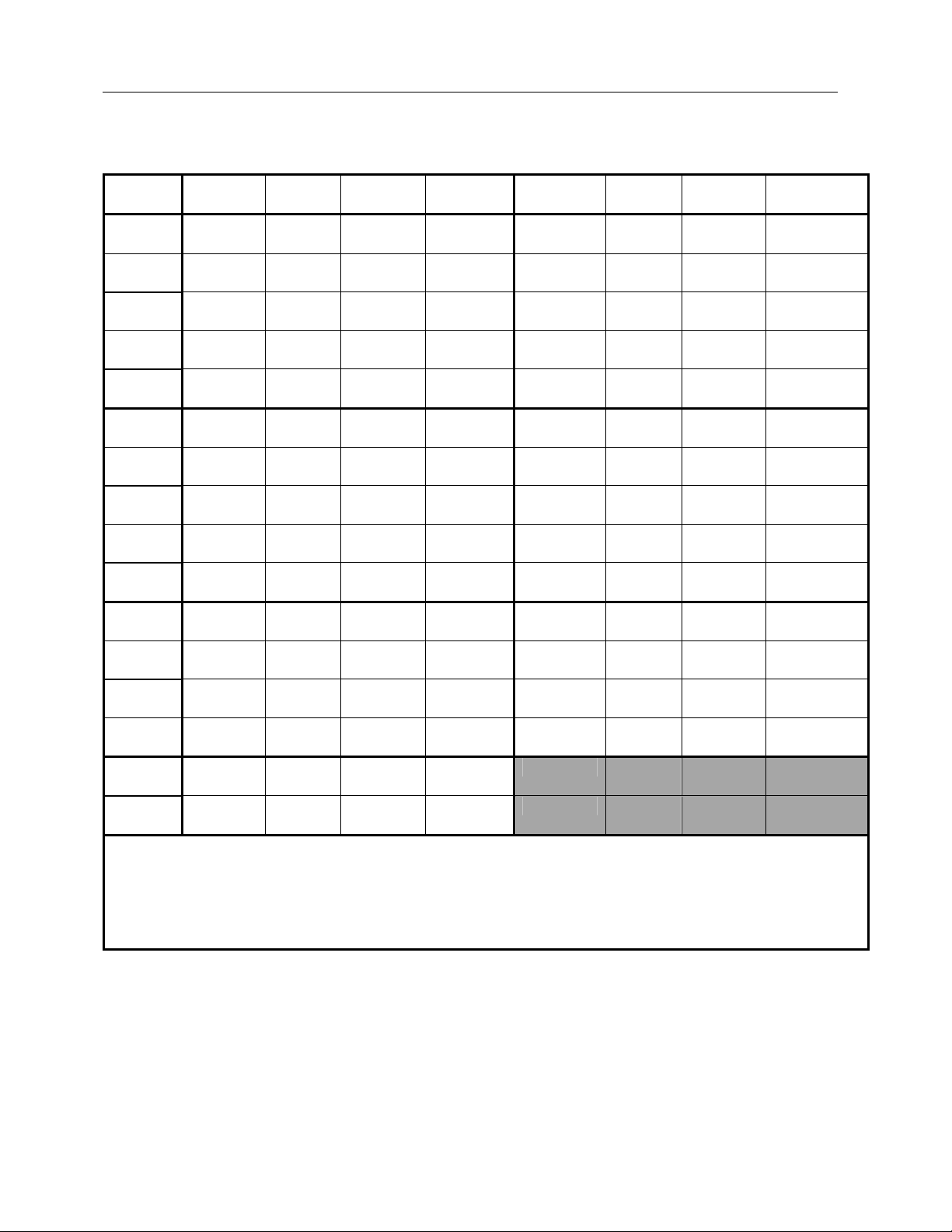
Electrometer Measurement Ranges
Table 1-1. Electrometer Measurement Ranges
Ion
Chamber
15 cc R 100 μ to
R/s 100 μ to
R/min 5 m to
R/hr 100 m to
R/frame** 2 μ to
150 cc R 10 μ to 2 6 μ 0.1 μ Gy 0.1 μ to
R/s 10 μ to 2 6 μ 0.1 μ Gy/s 0.1 μ to
R/min 0.5 m to
R/hr 10 m to
R/frame** 0.2 μ to
150 cc
VLDR
R/min 0.1 m to
R/hr 2 m to
R/frame** 0.04 μ to
Electrical
Units
A 1 p to
Values for ion chambers are calculated using nominal sensitivities:
15 cc: 2.4 x 10
150 cc: 2.4 x 10
* Very Low Dose Rate effective range at 5% resolution steps
** At 60 frames/s (1 to 120 frames/ selectable).
*** IEC 61674 effective range at 1% resolution steps
Units Effective
Range***
20
20
1200
72 k
333 m
120
7.2 k
33 m
R/s 2 μ to 2* N/A 0.1 μ Gy/s 0.02 μ to
120*
7.2 k*
33 m*
C 1 p to
100 n
100 n
8
R/C
7
R/C
Threshold Resolution
Step Size
60 μ
60 μ 1 μ Gy/s 1 μ to 0.2
3.6 m 50 μ Gy/min 50 μ to
216 m 1 m Gy/hr 1 m to
1μ 0.02 μ Gy/frame** 0.02 μ to
0.36 m 5 μ Gy/min 5 μ to 1.2 3.15 μ 0.05 μ
21.6 m 0.1 m Gy/hr 0.1 m to
0.1μ 0.002 μ Gy/frame** 0.002 μ
N/A 5 μ Gy/min 1 μ to
N/A 0.1 m Gy/hr 0.02 m to
N/A 0.002 μ Gy/frame** 0.4 n
0.5 pC 0.01 p
250 fA 0.01 p
1 μ Gy 1 μ to 0.2
Units
Effective
Range***
12
720
3.33m
0.02
0.02
72
to 0.33 m
0.02*
1.2*
72*
0.33 m*
Threshold Resolution
Step Size
.52 μ
.52 μ
31.5 μ
1.89 m
.008 μ
.052 μ 0.001 μ
.052 μ 0.001 μ
.189 m 0.001 m
0.8 n 0.02 n
N/A 0.001 μ
N/A 0.05 μ
N/A 0.001 m
N/A 0.02 n
0.01 μ
0.01 μ
0.5 μ
0.01 m
0.2 n
1-4
Page 11

General Information
Specifications
1
Measurement Modes
Dosimeter Operation Only: In use when the Model 35080/80A/80B kVp Divider is not connected or
turned on.
Full-sensitivity Exposure: Automatic drift and offset compensation, and automatic post-exposure
display hold are performed in this mode. Measurement range covers a span from low-level image
intensifier inputs to unattenuated direct beams. Autoranging over five decades. Display updates at the
end of each exposure. When the Automatic Reset option is enabled, exposure start and end detection
are based on the exposure rate level crossing a 0.25 pA threshold. When the Automatic Reset option is
disabled, exposure start detection is based on the exposure rate level crossing a 0.25 pA threshold but
the exposure measurement is only reset by pressing the Reset/Measure key.
Full-sensitivity Exposure Rate: Automatic offset compensation and nonlinear digital filtering are
performed in this mode. Autoranging provides five decades of sensitivity ranges. The measurement
range covers a span from low-level image intensifier inputs to unattenuated direct beams. Display
updates once per second. Differentiation between exposure on and off condition based on 0.25 pA
threshold.
Very Low Dose Rate (VLDR): This mode is only for making very low dose rate measurements. Nonlinear
digital filtering and autoranging provide five decades of sensitivity ranges. Display updates once per
second. In this mode, automatic current offset and drift compensation is disabled. As a result, the system
leakage (includes dosimeter, cable and ion chamber) is displayed and must be compensated for. This
option should only be used with ion chambers suitable for very low dose rate measurements.
Dosimeter with kVp and Time Readout Operation: In use when the Model 35080/80A/80B kVp Divider
is connected and a filter pack is selected from the Model 35050AT Dosimeter's front panel.
Tri-measurement Exposure: A single shot, direct beam measurement of exposure, kVp, and time.
Autoranging across three-decade ranges and auto reset between exposures. Display updates following
each exposure. Exposure start and stop based on detection of voltage from the Model 35080/80A/80B
kVp Divider in excess of minimum kV for selected pack. A measurement delay of up to 999 ms may be
used to skip over unwanted portions of an exposure. To prevent measurement of spurious signals, the
35050AT Dosimeter can be set to ignore exposures of less than 5ms.
Dual-measurement Exposure Rate: A simultaneous measurement of kVp and exposure rate. The
display updates once per second. Autoranging across three-decade ranges provide adequate sensitivity
for direct beam measurements. Display updates approximately once each second.
Customization
A customization program, contained on a compact disk, is included as part of a Model 10100AT TRIAD
Field Service Kit.
The customization program runs on any IBM-PC or compatible computer. A cable and adapters are also
furnished with the kit and provide means of interconnecting the computer's and the Model 35050AT
Dosimeter's serial communications ports.
The program allows the user to modify the contents of the Model 35050AT Dosimeter's non-volatile
memory, and thus determine a number of important operating parameters for the Model 35050AT
Dosimeter. These are listed below:
1. All electrical calibration factors
2. All unit, ion chamber, and kV filter pack descriptions and conversion factors
3. Temperature and pressure unit types for use with air density corrections:
In degrees Fahrenheit, Celsius and Kelvin
In inches of Hg, mm of Hg, milliBars, hectoPascal, feet relative to sea level, and meters relative to
sea level
1-5
Page 12

10100AT
Operators Manual
4. Number of minutes to auto power-down, from 1 to 255
5. Optional Power-On and Test screen messages
Display
The display is a two-line, 20-character alphanumeric PLED (polymer light emitting diode) display with an
approximate character height of 0.5 cm. The display shows all ion chamber/kV filter pack identification
information, numerical measurement results, and other information such as battery level and calibration
date.
Bias Voltage Supply
An electronic bias supply is fixed at a nominal 310 V. The bias voltage is removed from the triaxial input
connector at instrument turnoff. Internal low and high bias voltage test limits are set at 300 and 325 V
respectively.
Power
Continuous operational life of approximately thirty hours is provided by six “AA” alkaline batteries. Auto
power-down feature turns off unit after user-selected period (1-255 min) of unattended operation.
An AC adapter allows line current operation. When the AC adapter is in use, no current is drawn from the
batteries. When the AC adapter is in use, the auto power down feature is disabled, providing continuous
operation. The AC adapter is an unregulated 9v, 200 mA adapter with a center negative, 2 .1 mm plug.
Note: before auto turnoff, unit stores selections of ion chamber, units, and kVp filter pack in nonvolatile
memory. Eliminates manual reselection at next power-up. The default factory setting for the automatic
power-down feature is 15 minutes.
Control Buttons
Power On/Off: initiates power-up and -down sequences
Detector Select: selection of ion chambers, kV filter packs
Units Select: selects measurement units, frame rates
Reset/Measure: starts measurement, provides manual reset (auto reset function is also available in the
Model 35050AT Dosimeter)
Air Density: sets ambient temperature and pressure
Options: selects measurement options and displays diagnostic information such as supply level, ion
chamber leakage, bias voltage, and other diagnostic information
Up, Down: scrolls through list of screen selections, increments / decrements numeric entries. Holding
down the up or down key increases scroll speed.
1-6
Page 13

General Information
Specifications
1
Connections
Model 35080/80A/80B kVp Divider Interface: A coaxial-BNC connector used for measurement of kVp and
exposure time.
Computer Interface: RS-232-C Serial Port offers full duplex communication with XON/XOFF handshaking.
Connector is RJ-45 (female) with DCE configuration. Data format is 8 bits, no parity, and one stop bit.
Data rate is fixed at 9,600 baud. Interface provides full instrument control, calibration, and automation.
Ion Chamber Input: A triaxial-BNC input connector: collector and guard positive-biased relative to ion
chamber body/dosimeter chassis.
Power: 2.1mm DC Power Jack, power input for an unregulated 9v, 200 mA adapter with a center
negative, 2.1 mm plug.
Models 96035B, 96020C Diagnostic Ion Chambers
Energy Range:
96035B: 25 kVp to 150 kVp
96020C: 30 kVp to 150 kVp
Calibration: pair of ion chambers with NIST-traceable calibration and 3% system calibration with Model
35050AT Dosimeter. Ion chambers are calibrated for use at 22°C and 760 mm Hg. Real time
measurement or front panel selection of ambient temperature and pressure allow for corrected readings
at other conditions.
Nominal Sensitivity:
8
96035B: 2.35 x 10
radiography and mammography.
96020C: 2.1 x 10
measurements
Multiply values by 0.00876 to convert from R to Gy.
Construction:
96035B: Graphite-coated acrylic, parallel-plate, air-vented
96020C: Composite graphite-filled thermoplastic, parallel-plate, air-vented
Volumes:
96035B: --15 cc
96020C: --150 cc
R/C (2.06 x 10⁶ Gy/C). Flat response is suitable for both conventional diagnostic
7
R/C (1.84 x 10⁵ Gy/C), optimized for low-level image intensifier and cine
NOTE
See Appendix B and C in this instruction manual for
complete specifications on the Models 96020C and
96035B Ion Chambers.
Kit Accessories
Cable: (38208) 20 ft (6.1 m) Coax/Triax Cable
Test Stand: (37581) machined stainless steel upright rod with baseplate, ion chamber holder, Model
35080/80A/80B kVp Divider holder, and tray for HVL filters, which includes the ion chamber stem
(32147).
1-7
Page 14

10100AT
Operators Manual
Customization Kit: (37594) includes software on CD and a 6 ft (2 m) RS-232 interface cable with adapters
for PC- and AT-type computers.
Instruction Manuals: Model 10100AT TRIAD Field Service Kit Operator's Instruction Manual (38651).
HVL Filter Set: (37668) set of nine aluminum filters for half-value layer measurements: one -- 2 mm, two -
- 1 mm, two -- 0.5 mm, three -- 0.1 mm, and one -- 0.2 mm.
Kit Carrying Case: (37500D) high-density polyethylene (HDPE) plastic absorbs impact to protect contents.
Molded parallel ribs for strength. Corrosion-resistant hardware and locks. Custom-cut, high-quality foam
interiors surround and protect standard kit equipment and accessories. The case is gasketed to exclude
dust and moisture.
Environment
Operating: 0° to 50°C; relative humidity 20% - 80% non-condensing
Storage: -25° to 65°C
Kit Dimensions, Weight
Approximately 46 cm long x 33 cm wide x 15 cm deep (18 in x 13 in x 6 in); approximately 6.4 kg (14 lb).
kVp Measurement Accuracy and Method
The Model 35050AT Dosimeter will typically add an uncertainty of ± 2 mV to the voltage produced by the
Model 35080/80A/80B kVp Divider for a well behaved (quiet and constant) voltage waveform. The
accuracy of the peak detection method will be dependent upon both the shape of the kV waveform, and
the amount of noise present in the signal produced by the kVp divider. Based on sampling the output of
the kVp divider at a rate of 5 kHz, the peak voltage is determined by examining a 50 ms wide segment of
these samples. In selecting the data segment to be analyzed, a delay of one-tenth of the total exposure
time is inserted. When a measurement delay is used, this occurs after the measurement delay time
elapses or with the first rising edge after the delay time elapses. Before peak detection occurs, the signal
is passed through a digital filter with 1 ms time constant. The digital filter is not used with the Mobile filter
pack
Exposure Time Measurement Accuracy and Method
When seconds are selected as exposure time units, the exposure time accuracy is ± 0.1% of reading ±
0.2 ms. The measurement method is based on a kV threshold crossing. The threshold is set at 75% of
the kVp, or the minimum kVp for the filter pack in use, whichever is greater. The maximum exposure time
is six seconds and the measurement resolution is 0.2 ms.
When pulses are selected as exposure time units, the exposure time accuracy is ± 1 pulse. The
measurement method is based on a kV threshold crossing; pulses are counted by detecting each
passage through a threshold on the rising and falling edges each pulse in the output waveform.
When a negative measurement delay is specified, the TRIAD TnT Dosimeter does not include the delay
time in the measured exposure time. A negative measurement delay should be used in cases when x-ray
generator filament preheat pulses or other waveform anomalies should be excluded from kV and
exposure time measurements.
When the measurement delay is positive, the TRIAD TnT Dosimeter includes the delay time in its
measured exposure time. A positive measurement delay should be used in cases when the kV waveform
contains leading edge overshoot or other waveform anomalies that should be excluded from kV
measurements but included in the exposure time measurement.
* Specifications subject to change without notice.
1-8
Page 15

General Information
Unpacking and Inspection
1
1.7 Unpacking and Inspection
The Model 10100AT TRIAD Field Service Kit was carefully inspected before shipment. Upon receiving
the service kit, carefully unpack all items from the shipping carton and check for any obvious signs of
physical damage that might have occurred during shipment. Report any damage to the shipping agent at
once. Retain the original packing material in case reshipment becomes necessary. The following items
are included with every Model 10100AT Service Kit shipment.
Standard System Components
• Model 35050AT Dosimeter/kVp Readout
• Model 10100AT TRIAD Field Service Kit Operator's Instruction Manual (38651)
• System Carrying Case (37500D)
• 15 cc and 150 cc Ion Chambers (96035B and 96020C)
• Test Stand (37581)
• 6.1 m (20 ft) Coax/Triax Cable (38208)
• Ion Chamber Stem (32147)
• HVL Filter Kit (37668)
• Spare Battery Holder (87-3)
• Customization Software Kit includes a compact disk, 2 m (6 ft) RS-232 Interface Cable, and adapters
for PC- and AT-type computers (37594)
• AC Adapter
Optional Equipment
The Model 35080/80A/80B Non-invasive kVp Divider - is compatible with the Model 10100AT when
used with the appropriate filter packs:
• Wide Range Filter Pack (37617)
• CT Filter Pack (33551)
• Cadmium K-Edge Mammo Filter Pack (37355)
• Linear Mammo Filter Pack (37351)
• Mobile Filter Pack Plus (37946)
• Low Range Filter Pack (38237)
Model 35035 mA/mAs Meter - measures anode current (mA) and anode current and time product (mAs)
of x-ray generators.
TRIAD Toolkit for Excel (10500EXL) - is a complete software package for the TRIAD that includes an
Excel Add-In, called TRIAD Tool and Excel templates that may be used to evaluate the performance of
radiographic, mammographic, and fluoroscopic x-ray machines.
TRIAD QA Software (37978) - is a quality assurance software package for IBM-PC. It simplifies testing
of exposure reproducibility, linearity, kVp, timer accuracy, and HVL.
Cable and Reel Assembly (38209) - is used to keep the 6.1 m (20 ft) coax/triax cable tangle free.
1-9
Page 16

10100AT
G
Operators Manual
1.8 Getting Started
The Model 35050AT Dosimeter/kVp/Time Readout is a highly sophisticated instrument with many
capabilities. Although there are a number of complex aspects about the instrument, you can use the
following procedure to get your instrument up and running quickly. For more detailed information, you
should consult section 2 of this manual.
1. Carefully unpack your Service Kit as described in section 1.7.
a. Connect the supplied triaxial cable to the case side input jack. Connect an appropriate ion
chamber to the other end of the triaxial cable. Position the chamber where required.
To prevent electrical shock, the Model 35050AT
Dosimeter should always be turned off when
connecting or disconnecting an ion chamber or
triaxial cable.
2. a. If use of the Model 35080/80A/80B kVp Divider is intended, connect its output to input of the
Model 35050AT Dosimeter using the coaxial cable provided. Position the kVp divider in the
beam.
Make certain that the color of the cable boot
matches the color indicator around the connector of
the instrument.
2. b. If using the AC adapter, plug the adapter into a suitable power outlet and plug the 2.1mm plug
fully into the power jack on the side of the unit.
Only use the supplied AC adapter. Use of AC
adapters other than the one supplied with the unit
may damage the unit and void the warranty.
3. a. Depress the front panel POWER ON/OFF button for approximately one second to apply power
to the instrument. The instrument will power-up through a series of screens.
b. If a kVp divider is in use, set its switch to the RUN position and plug in desired filter pack.
4. a. At the Detector Select screen, make sure the ion chamber in use is indicated. If not, press the
UP or DOWN buttons until it is. If air density corrections are desired, find an ion chamber with
ADC in its description. If very low dose rate measurements are desired, find an ion chamber
with VLDR in its description.
b. If using a Model 35080/80A/80B kVp Divider, press the DETECTOR SELECT button and then
press the UP or DOWN buttons until the proper filter pack is selected.
c. If a kVp divider is not in use, press the DETECTOR SELECT button and then press the UP or
DOWN buttons until the filter pack selection displays “35080/80A Not Used”.
WARNIN
NOTE
NOTE
1-10
Page 17

General Information
Getting Started
5. Press the UNITS SELECT button if an integrated exposure is to be measured. Or, if exposure rate
is desired, these same units may be chosen with a timebase of seconds, minutes or hours.
Additionally, per frame and amperes are available. Select desired units of measurement by
pressing the UNITS SELECT button. Change the selection by pressing the UP or DOWN buttons.
If exposure/frame units are selected, the user must set the frame rate at this screen.
6. If an ion chamber using air density corrections is selected, press the AIR DENSITY button to
display the Air Density screen. If the temperature & pressure mode has been set to Automatic
Sense, the measured ambient temperature and pressure will be displayed. If the temperature &
pressure mode has been set to Manual Entry, the last used temperature and pressure will be
displayed. Set temperature and pressure to match ambient conditions.
NOTE
1
When air density corrections are in effect, a “ADC”
annunciator will appear on the Measurement
screen. In Automatic Sense mode the ambient
temperature and pressure are updated each time
RESET/MEASURE is pressed.
7. Press and release the RESET/MEASURE button to place the dosimeter in the measurement mode.
8. Make the exposure. Following an exposure, the display will be updated with measurement results
for the exposure. Additional exposures may be made at this point as the dosimeter will detect each
exposure and automatically update the display.
Complete detailed operation concerning the Model 35050AT Dosimeter front panel operation may be
found in section 2 of this manual, including the use of the Model 35080/80A/80B kVp Divider. If you wish
to control these functions over the RS-232 Interface Cable, consult the Model 35050A Programmer's
Instruction Manual.
1-11
Page 18

10100AT
Operators Manual
(Blank Page)
Page 19

Operation
Introduction
Section 2
Operation
2.1 Introduction
Operation of the Model 35050AT Dosimeter may be divided into two general categories: front panel
operation and RS-232 bus operation. This section contains information necessary to use the instrument
from the front panel. Note that many of these functions can also be programmed over the RS-232 bus,
as described in the Model 35050A Programmer's Instruction Manual.
The following paragraphs contain a complete description of the Model 35050AT Dosimeter front panel
operation. First a complete description of each front panel function is presented. Next the complete
procedure for each of the measuring functions is presented.
2.2 Front Panel Familiarization
2
The front panel of the Model 35050AT Dosimeter is shown in Figure 2-1. The front panel may be divided
into two sections: control buttons and display. The following paragraphs describe each of these items in
detail.
Figure 2-1. The Model 35050AT Dosimeter Front Panel
2-1
Page 20

10100AT
Operators Manual
2.2.1 Control Buttons
All front panel control buttons are momentary contact switches, but their functions are firmware latched
once depressed for even a short period of time. They are membrane type switches that provide a definite
tactile indication of operation.
Power On/Off
This button controls the power to the instrument. Depressing this button for approximately one second
turns the power on. Depressing and releasing the button a second time turns the power off.
When the power-up screens sequence is still in
progress, depressing any button will have no effect.
Similarly, depressing any button during the powerdown sequence will have no effect.
In the event of no button depression, no exposure, no operating kVp divider connected, or no RS-232
communication for a user-defined period; the instrument will automatically save its current settings and
turn its power off. Note that any measurement values displayed at power down will be lost. For
additional details on power-up screens, see section 2.4.
At next power-up, the unit will resume operation with these same selections. In addition, at power-up, the
unit will automatically advance through four basic status or self-test screens and then automatically
invoke the DETECTOR SELECT screen before returning control to the front panel buttons. This screen is
shown in Figure 2-1.
NOTE
Options
This button is used to select various measurement options and display of a series of test screens. For
additional details on test screens, see section 2.5. The complete wraparound list may be examined by
repeatedly pressing the Options button.
Air Density
This button causes display of the temperature and barometric pressure used for vented ion chamber
corrections. When the temperature & pressure mode is set to Automatic Sense, pressing the Air Density
button causes the ambient temperature and pressure to be displayed. When the temperature & pressure
mode is set to Manual Entry, the button has a toggle function: momentarily depressing it selects whether
temperature or barometric pressure may be adjusted. The current variable is indicated by the “greater
than” symbol (>) as first character in the display line; hereafter, this is referred to as the cursor. The
current variable may then be changed in value, if desired, by use of the UP and DOWN buttons. Air
density corrections to the exposure and exposure rate displays will be made only if 1) radiological units
(not A or C) have been selected, and 2) an ion chamber with air density corrections enabled has been
selected. When air density corrections are in effect, an “ADC” annunciator will be displayed on the
measurement screen. In the event that the temperature/pressure sensor becomes non functional, an
error message, “Temp & Press Error Use Manual Entry” is displayed and only the manual temperature
and pressure entry mode is available.
Units Select
This button causes display of the selected radiological or electrical units and cine frames per second.
This button also has the toggle function to cursor select the units or frame rate for changing. Changes
may then be made by means of the UP and DOWN buttons. The exposure and exposure rate displays
will be affected by the frame rate setting only if units of exposure per frame (R/frame, Sv/frame, etc.) have
been selected.
2-2
Page 21
Operation
Front Panel Familiarization
2
Detector Select
This button causes display of the identity of the ion chamber and kVp filter pack last used. This button
also has the toggle function to cursor select which chamber and/or filter pack is to be currently used. If
different, changes may then be made by means of the UP and DOWN buttons. The filter pack selection
is used only when a Model 35080/80A/80B kVp Divider is connected.
Reset/Measure
This button is used to both begin and reset the measurement process. When the Exposure Reset option
is set to Manual, indicated by
exposures to clear the display. When the Exposure Reset option is set to Automatic, this is not required
because of the automatic reset feature of the Model 35050AT Dosimeter. The manual reset feature is
only active in the Full-Sensitivity Exposure mode.
in the upper right corner, this button may be depressed between
2.2.2 Display
The display, located on the upper left-hand corner of the front panel, is a two line, twenty character per
line, alphanumeric PLED (polymer light emitting diode) display module. This module performs all visual
indications for the manual operator.
Annunciators
The battery/supply level and ion chamber bias potential are measured regularly by the instrument in a
background mode. Should either level go outside of preset limits, an annunciator is displayed. The
preset limits are given below.
Bias voltage limits 300 to 325 volts
Power battery limits 5.9 to 9.6 volts
The low battery limit of 5.9 V has been chosen to provide approximately two hours of useful battery life
following the initial display of the low battery annunciator.
NOTE
The battery voltage is measured at the input of the
5-volt regulator, after some drops in fuse, switch,
wiring, etc. There will be a discrepancy of several
tenths of a volt from the actual battery voltage.
2.3 Connector Familiarization
There are four external connectors provided on the Model 35050AT Dosimeter case sides. On the side
left of the front panel (front view) are the ion chamber and kVp divider connectors (marked by a yellow
ring). The following paragraphs detail the purpose and use of these connectors. On the side right of the
front panel are the DC power jack and the RS-232 connector. Information on RS-232 communication is
in the Model 35050A Programmer's Instruction Manual that is available upon request.
2-3
Page 22

10100AT
CAUTIO
Operators Manual
2.3.1 Ion Chamber Connector
Never connect a coaxial-BNC type cable to the
Model 35050AT Dosimeter's triaxial ion chamber
input connector. Doing so may damage the ion
chamber input connector.
WARNING
The central pin and inner shield shell of this
connector are operated at 300 volts above the
outer shell and instrument case. Although this
potential is energy and current limited, care should
be taken to avoid unnecessary and possibly
hazardous shocks. Mating and unmating to this
connector (or to the other end of a cable already
connected to it) should be done only when the
instrument is powered down. Within a few seconds
of turnoff, the high voltage is internally discharged
making such connections safe and convenient.
The connector is a triaxial-BNC female with dust cap and chain. It connects to the supplied coax/triax
cable or other low-noise triaxial-BNC male cables. And, by means of which, the Models 96020C Ion
Chamber, Model 96035B Ion Chamber, and other ion chambers can be operated with the Model
35050AT Dosimeter.
N
The connector is side-mounted to avoid contaminating spills and dust, but putting its dust cap in place
whenever a cable is not connected will help assure long service without leakage problems.
2.3.2 kVp Divider Connectors
The connector is a BNC jack marked with a yellow ring. It is the opposite gender of the usual panel
mounted BNC connector to prevent accidental connection of the triax cable to the BNC connector, and
vice versa. Such a cable connector mix up will damage some or all connectors involved. The male to
female BNC coaxial cable (as indicated by yellow boots) provides the connection between the Model
35080/80A/80B kVp Divider and the Model 35050AT Dosimeter / kVp Readout.
2.4 Power-Up Self-Test and Display Messages
When the instrument is powered up by pressing and releasing the POWER ON/OFF button on the front
panel, the following sequence of screens will be displayed:
1. Pixel test
2. Last calibration and software revision date (5 seconds)
3. Instrument power level in volts and HI, LO or OK advisory (5 seconds). If the unit is operating on
battery power, the displayed battery voltage will be between 5.9 and 9.6 volts. If the unit is powered
by its AC adapter, the displayed battery voltage will be between 10 and 13 volts.
2-4
Page 23

Operation
Power-Up Self-Test and Display Messages
NOTE
2
If the AC adapter is plugged into the instrument, but
is not plugged into an AC power source, the Supply
Level will be reduced by several tenths of a volt.
This is due to the additional components that are
switched into the power circuit when the AC
adapter is plugged into the unit. For best
performance on battery power, unplug the AC
adapter from the unit when not in use.
4. Optional power on screen displays user selected information (5 seconds):
This screen will be skipped if blank screen was specified using customization software.
During this opening screen sequence, pressing any front panel button will have no effect. The sequence
ends in DETECTOR SELECT. The last selected detector will be displayed on the screen. Other
functions or another detector may now be selected with the front panel buttons.
2.5 Using the Options Button
Pressing the OPTIONS button, when in any other function, will display one of the status/option screens.
Repeatedly pressing the OPTIONS button again will move the display through twelve status/option
screens as follows:
1. Last calibration and software revision dates
2. Optional test screen, can be skipped by customization
3. Supply Level in volts and HI, LO or OK advisory. When battery power is in use, the battery voltage
is displayed. When the AC adapter is in use, the AC adapter voltage is displayed.
4. System leakage current measuring mode without offset current subtraction. Enables operator to
directly see the ion chamber, cable, and dosimeter leakage current. See section 2.6.1 for more
information.
5. System bias level in volts and HI, LO or OK advisory
6. Ion chamber calibration factor in use: 4 digits plus exponent, dimensioned in either
Roentgens/Coulombs or Grays/Coulombs depending on option chosen during customization.
Factor also includes air density correction if applicable.
7. Voltage measured at Data Terminal Ready (DTR) line of RS-232 port
8. Temperature & Pressure Mode selection. Pressing the up or down button toggles between
Automatic Sensing of temperature and pressure or Manual Entry of temperature and pressure.
9. Short Exposure (< 5ms) selection. Pressing the up or down button toggles between Accept and
Ignore. Accept allows the 35050AT to measure exposures that are less than 5 milliseconds in
duration. When ignore is selected, the 35050AT ignores exposures that are less than 5 milliseconds
in duration. This is useful when spurious signals trigger unintended measurements. This feature is
only active when the 35050AT is in the Tri-measurement Exposure mode (when the 35080 is used).
10. kV Measurement Delay entry. Pressing the up or down buttons increments or decrements the
measurement delay. The measurement delay range is –999 to +999 milliseconds and can be set in
one-millisecond increments. The polarity of the measurement delay only affects how exposure time
measurements are performed. When a negative measurement delay is specified, the 35050AT
does not include the delay time in the measured exposure time. When the measurement delay is
positive, the 35050AT includes the delay time in its measured exposure time. This feature is only
active when the 35050AT is in the Tri-measurement Exposure mode (when the 35080 is used).
2-5
Page 24

10100AT
Operators Manual
11. Exposure Reset selection. Pressing the up or down button toggles between Automatic and Manual.
When the Exposure Reset option is set to Automatic, Model 35050AT Dosimeter automatically
resets between exposures; exposure start and end detection are based on the exposure rate level
crossing a 0.25 pA threshold. When the Exposure Reset option is set to Manual, this button may be
depressed between exposures to clear the display. A
the display when the Manual Reset option is active. Exposure start detection is based on the
exposure rate level crossing a 0.25 pA threshold but the exposure measurement is only reset by
pressing the Reset/Measure button. The manual reset feature is only active in the Full-sensitivity
Exposure mode.
12. Exposure Time Units selection. Pressing the up or down button toggles between Seconds and
Pulses. When Seconds are selected as exposure time units, exposure time is measured between
the first and last passage through the kV threshold. The displayed units are milliseconds (ms) or
seconds (s). The threshold is set at 75% of the kVp, or the minimum kVp for the filter pack in use,
whichever is greater. When Pulses are selected as exposure time units, exposure time is displayed
in pulses (P), and pulses are counted by detecting each passage through a threshold on the rising
and falling edges each pulse in the output waveform.
symbol appears in the upper right corner of
2.6 Basic Measurement Techniques
2.6.1 General Considerations
It will be helpful to the user to understand the presence of several automatic compensations being
performed during measurements and how they could affect the measurements under certain
circumstances.
Automatic Voltage Offset and Drift Compensation
The instrument automatically measures the voltage offset of the electrometer and subtracts the value
from the exposure and exposure rate measurement results.
Automatic Current Offset and Drift Compensation
In the usual situation, this feature is transparent and amounts to system leakage current being nulled from
the measurements. In order to do this, both a short-term history of the leakage current and the
establishment of a leakage/“real” current threshold must be made.
The threshold is set at 0.25 pA and only a few seconds are required for an accurate leakage level
assessment. In the typical case, system leakage current is on the order of 10 fA and reasonably steady.
It may be viewed at any time by going to the OPTIONS and scrolling to the System Leakage screen.
When it approaches the current threshold level and/or becomes highly erratic, the system may improperly
compensate the measurement value.
Another consideration of higher, but suppressed, leakage levels is that the automatic electrometer
integrator reset frequency is raised. This increases the small, but finite possibility, that a reset may occur
during an exposure and thereby lose some of its value. With low system leakage and manually resetting
just before the exposure, this possibility is precluded. In the case where the Model 35050AT Dosimeter
detects the start of an exposure immediately following an automatic reset, an error message will be
displayed advising the user to repeat the exposure.
For several reasons, then, it is good operator practice to regularly check for a low system leakage level.
Experience should serve as a guide to how often this needs to be done and in what circumstances.
Similarly, ten seconds or so should be allowed to elapse between the last triaxial cable or chamber
movement or other disturbances to the high impedance part of the system before commencing an
exposure--so that the “correct” history is applied to the measurement.
2-6
Page 25

Operation
Basic Measurement Techniques
Important implications of the 0.25 pA threshold for exposure rate measurements and the 0.5 pC threshold
for integrated exposure measurements in the case of integral exposure are the minimum radiological
quantities that can be measured.
2
Table 2-1. Threshold Minimum Roentgen readings
Ion Chamber Measurement Units Minimum Reading
15 cc R/s
R/min 3.6 m
R/hr .22
R/frame
R
150 cc R/s
R/min .36 m
R/hr 22 m
R/frame
R
To find minimum readings in other radiological units, use the following multipliers of the roentgen factors:
60 μ
1 μ
60 μ
6 μ
0.1 μ
6 μ
0.000258 for Coulombs/kg air
0.00876 for Grays (in air)
0.01 for Sieverts (in air)
Ion Chamber Selection
The primary purpose of the Model 35050AT Dosimeter is to measure the ionizing radiation outputs of
typical diagnostic x-ray machines. This will likely be done with either of the two ion chambers standard in
the Model 10100AT TRIAD Field Service Kit: Model 96020C Ion Chamber, 150 cc or Model 96035B Ion
Chamber, 15 cc. Typical units of use will be exposure, exposure rate or exposure per frame.
The choice of which ion chamber to use will depend upon the sensitivity required, the beam size, beam
accessing port dimensions or the performance of a special function (e.g. CT probe).
Once a suitable ion chamber is selected, it is interconnected with the Model 35050AT Dosimeter by
means of the 6.1 m (20 ft) low-noise triaxial cable supplied and stably positioned at the measurement
point of interest by means of the test stand (see section 2.9) or ion chamber cable stem (see section
2.10) or other means. The dosimeter may be located where convenient and where both the dosimeter
and the operator are out of the radiation field. The dosimeter may now be turned on.
Verify Ion Chamber Selection
After the opening screen sequence, the instrument will go to the DETECTOR SELECT screen and await
a key press. If the ion chamber in use is not displayed, press the UP or DOWN buttons until it is.
Make sure that air density correction or no air density correction is what is desired--or required by the
nature of the detector, e.g., sealed chamber. If air density corrections are desired see section 2.2.1 and
2.11.2.
If very low dose rate measurements are desired, find an ion chamber with VLDR in its description. This
option should only be used with ion chambers suitable for very low dose rate measurements
Automatic Temperature & Pressure Sensing
The Model 35050AT Dosimeter contains an integrated temperature/pressure sensor. When using the
automatic temperature and pressure sensing feature, the measured temperature is the internal
2-7
Page 26

10100AT
Operators Manual
temperature of the Model 35050AT, TRIAD TnT Dosimeter. This temperature may not be the same
temperature as the Ion Chamber that is in use. In normal use, the internal operating temperature of the
35050AT may be 1 to 2°C above ambient temperature. This operating temperature is normally achieved
within 15 minutes of turn on.
Adequate time must be allowed for the Dosimeter and Ion Chamber to reach thermal equilibrium before
automatic temperature sensing is used. For a large temperature differential, the thermal equilibrium time
of the 35050AT may be up to 2 hours. If it is not possible to allow the instrument to reach thermal
equilibrium, manual entry of temperature and pressure is recommended. A 3°C change in temperature
results in approximately a 1% change in air density correction factor (ADC).
The housing of the Model 35050AT Dosimeter and its ion chambers are vented to atmospheric pressure;
as a result, there should be no difference between the atmospheric pressure measured by Model
35050AT Dosimeter and the actual atmospheric pressure of the ion chamber.
A 3°C change in temperature results in approximately a 1% change in air density correction factor (ADC);
an 8-mmHg change in barometric pressure results in approximately a 1% change in ADC.
In the event that the temperature/pressure sensor becomes non functional, an error message, “Temp &
Press Error Use Manual Entry” is displayed and only the manual temperature and pressure entry mode is
available.
kV Measurement Delay
A kV measurement delay may be used to postpone the start of data analysis in order to skip over
waveform anomalies (such as overshoots or filament preheat effects), which may occur at the beginning
of an exposure. This feature is only active in the Tri-measurement Exposure mode (when the 35080 is
used).
When a delay is used, the 35050AT waits for the specified delay time after the beginning of an exposure
before starting data analysis. If no radiation is detected after the delay time has elapsed, data analysis is
delayed for up to one second after the delay time has elapsed. If no radiation is detected within one
second after the delay time has elapsed, the 35050AT assumes that no exposure has occurred and
displays the "-delay" message.
The delay range is from -999 to +999 milliseconds, and the polarity of the measurement delay only affects
how exposure time measurements are performed.
When a negative measurement delay is specified, the 35050AT does not include the delay time in the
measured exposure time. A negative measurement delay should be used in cases when x-ray generator
filament preheat pulses or other waveform anomalies should be excluded from kV and exposure time
measurements.
When the measurement delay is positive, the 35050AT includes the delay time in its measured exposure
time. A positive measurement delay should be used in cases when the kV waveform contains leading
edge overshoot anomalies that should be excluded from kV measurements but included in the exposure
time measurement.
Exposure Time Units
When seconds are selected as exposure time units, the measurement method is based on a kV threshold
crossing. The threshold is set at 75% of the kVp, or the minimum kVp for the filter pack in use, whichever
is greater. The maximum exposure time is six seconds and the measurement resolution is 0.2 ms.
Exposure time is displayed in milliseconds (ms) or seconds (s).
When Pulses are selected as exposure time units, the 35050AT counts the number of x-ray pulses in a
pulsed or single-phase radiographic exposure. Pulses are counted by detecting each passage through a
threshold on the rising and falling edges each pulse in the output waveform. Exposure time is displayed in
pulses (P). This is primarily for use with single-phase full and half-wave rectified generators. Pulse
counting will not function properly on single-phase generators employing output filter capacitors to smooth
the generator's output because the generator's output does not drop to zero between pulses.
2-8
Page 27

Operation
Basic Measurement Techniques
2
2.6.2 Making Exposure Measurements
Select Exposure Unit
The following integral exposure units are available for selection:
Exposure: Roentgens or Coulombs/kg air
Absorbed Dose: Grays (in air)
Dose Equivalent: Sieverts (x, gamma, or electron source and N=1 for air)
Charge: Coulombs (for the unlisted ion chamber)
Press UNITS SELECT button and use UP or DOWN buttons until the cursor is on the desired unit.
Taking the Exposure
Press RESET/MEASURE just before the exposure. Make the exposure. The exposure value will be
displayed.
Automatic / Manual Reset & Hold
When the Exposure Reset option is set to Automatic Reset, the electrometer is reset once the instrument
senses the exposure is over. The final calculated value of the exposure is held on the display until either
another above threshold exposure occurs, in which case the old value is discarded and the new value is
displayed; or there is function change or power down. The instrument treats exposures separated by less
than two seconds as single exposures.
When the Exposure Reset option is set to Manual Reset, the electrometer is only reset when the
Reset/Measure button is depressed. The final calculated value of the exposure is held on the display until
Reset/Measure button is depressed, in which case the old value is discarded and the display is reset to
zero. When the Manual Reset option is active, the
display.
Resetting of the electrometer takes approximately 100 ms to complete. If an exposure starts while the
electrometer is being reset, the result is an erroneous measurement. Instead of displaying the erroneous
measurement, the display would read:
Simply repeat the exposure to clear the message and display a new measurement result.
symbol appears in the upper right corner of the
2.6.3 Making Exposure Rate Measurements
For selection of ion chamber, verification of ion chamber with the instrument, minimum radiological
quantities, and general considerations please refer to the discussions in section 2.6.1, as they apply here
equally well. In addition, there are some aspects that are unique to exposure rate measurements.
Nonlinear Filter
Incorporated in the instrument's firmware is a digital nonlinear filter that responds quickly to significant
changes in exposure rate, but possesses a much larger time constant for small changes, such as
measurement system noise.
Realtime Display
While operating in the exposure rate mode, the display is updated at an approximate rate of once per
second. Each new display value corresponds to the average exposure rate present since the previous
2-9
Page 28

10100AT
Operators Manual
display update. This differs from operation in the exposure mode where the display is updated and held
following each exposure.
Very Low Dose Rate Measurements
Very low dose rate measurements are selected by pressing Detector Select and selecting an ion chamber
with VLDR in its description. This option should only be used with Ion Chambers suitable for very low
dose rate measurements. To add this measurement option to an ion chamber, using the Customization
Software, add “VLDR” to the chamber’s description. This option is only active in the Exposure Rate mode
(35080 not used).
In order to display very low dose rates in the VLDR measurement mode, automatic current offset and drift
compensation is disabled. As a result, system leakage (dosimeter, cable and ion chamber) is displayed
and should be subtracted from the rate reading. For instance, if the displayed leakage rate is 0.2 uR/sec
(beam off) and the rate with the beam on is 6.9 uR/sec, the actual rate is 6.7 uR/sec.
Allow at least five minutes of settling time after connecting the ion chamber and cable to the dosimeter
before making very low dose rate measurements. Settling time must also be allowed after moving the ion
chamber, cable or dosimeter. When making very low dose rate measurements, the ion chamber, cable
and dosimeter must be stationary; any movement can induce currents.
2.6.4 Use of the Model 35050AT Dosimeter as a kVp Divider Readout
For a full discussion of the Model 35080/80A/80B kVp Divider, the reader is referenced to its instruction
manual. The information given here only concerns the combined operation of the two instruments.
There are some general considerations that apply to both the Exposure Rate/kVp mode and the
Exposure/Time/kVp mode.
Interconnection & Power-Up Sequence
Use the supplied coaxial-BNC cable to connect the Model 35080A kVp Divider to the Model 35050AT
Dosimeter. (Take note of the color-coding of BNC cable boots and respective connectors on the
instruments.)
2-10
Page 29

Operation
Basic Measurement Techniques
2
CAUTION
Never connect a coaxial-BNC type cable to the
Model 35050AT Dosimeter's triaxial ion chamber
input connector. Doing so may damage the ion
chamber input connector.
Always power-up the Model 35050AT Dosimeter first and power it down last. Both instruments may now
be turned on.
kVp Divider Battery Check
With the Model 35050AT Dosimeter turned on, set the function selector of the Model 35080/80A/80B kVp
Divider to the BAT CHK position. The kVp divider battery measurement screen will be displayed by the
dosimeter. A battery voltage display between 7 and 9.6 volts will carry an advisory of OK with it. Below 7
volts, LO will be indicated. If a kVp value is displayed in the BAT CHK position, the battery is indeed
exhausted. Since the kVp divider is not under control of the readout, the operator must remember to
check battery voltage manually.
Filter Pack Selection & Verification
Select an appropriate kVp filter pack for the x-ray machine
involved and plug it into the Model 35080/80A/80B kVp Divider.
Position the kVp dividers long dimensional axis at right angles
to the x-ray tube axis, to avoid "heel" effect. The filter pack area
can be placed as close to the beam axis as the ion chamber
allows. Neither the ion chamber nor the kVp divider should
shadow the other.
X - R A Y
T U B E
Pushing DETECTOR SELECT should display the name of the
filter pack installed on the kVp divider. If it does not, scroll
through the filter packs until it does.
NOTE
Filter packs should not be exchanged between kVp
dividers. Each instrument and its filter pack(s) have
B E A M
T E S T
S T A N D
9 6 0 3 5 B
I O N
C H A M B E R
been carefully calibrated together as a unit. Always
check the calibration sheet serial numbers against the
actual combination. A mismatch can impact
measurement accuracy.
3 5 0 8 0 / 8 0 A / 8 0 B
L O N G
A X I S
O F
3 5 0 8 0
T O 3 5 0 5 0 A
T U B E
A X I S
Figure 2-3. The Model 35080/80A/80B kVp
Divider and Ion Chamber X-ray
Shot
2-11
Page 30

10100AT
Operators Manual
Internal Calibration Check
To use the cal check feature of the Model 35080/80A/80B kVp Divider, set the Model 35050AT Dosimeter
for exposure rate units (A, R/s, etc.). Set the function selector of the Model 35080/80A/80B kVp Divider
to the CAL position. After the Model 35050AT Dosimeter's RESET/MEASURE button is pressed the filter
pack cal level will be displayed in kVp. The Linear Mammo Filter Pack cannot show the calibration check
kVp, since it falls outside the specified kVp range.
Because the Model 35050AT Dosimeter automatically performs filter pack linearization corrections when
the Wide Range, CT, or Mobile Filter Pack is selected, the kVp level displayed by the Model 35050AT
Dosimeter will differ from the calibration kV level printed on the face of the filter pack. Table 2-2 gives the
Printed Calibration kV Level for each filter pack as well as the Corrected kVp Reading that should be
displayed by the Model 35050AT Dosimeter.
Table 2-2. Corrected kVp Readings for kV Filter Packs with Automatic Linearization Corrections
Filter Pack Type 37617C Wide Range 3351C CT 37946C Mobile
Printed Calibration kV Level 80 kV 124.4 kV 100.0 kV
Corrected kVp Reading 79.4 kVp 123.6 kVp 98.8 kVp
Nominal Calibration Voltage 0.400 V 0.644 V 0.600 V
The Nominal Calibration Voltage levels listed in Table 2-2 are also printed on the faces of the filter packs,
and may be read directly and without the effect of the Model 35050AT Dosimeter's automatic linearization
correction scheme by selecting the Test Pack from the Model 35050AT Dosimter's Detector Select
screen.
Dosimeter Range Reduction in kVp Modes
Because of the higher exposure rates associated with kVp determinations, the dosimeter is automatically
desensitized when in either kVp mode. This changes the minimum detectable quantities as follows
below.
An important implication of the 5-picoampere threshold in the case of kVp/Exposure Rate is that there are
minimum radiological quantities that can be read, depending on the ion chamber being used. Once
above the threshold, though, there will be good value resolution.
Table 2-3. Reduced Range, Minimum Roentgen Readings
Ion Chamber Measurement Units Minimum Reading
15 cc R/s 1.2 m
R/min 72 m
R/hr 4.3
R/frame*
150 cc R/s
R/min 7.2 m
R/hr .43
R/frame*
* at 60 frames/second
20 μ
120 μ
2 μ
2-12
Page 31

Operation
Basic Measurement Techniques
To find minimum readings in other radiological units, use the following multipliers to the roentgen factors
found above.
0.000258 for Coulombs/kg air
0.00876 for Grays (in air)
0.01 for Sieverts (in air)
2
kVp Out-of-Range Indications
If the peak kilovoltage during an exposure falls short of the filter pack's specified kVp range, the display
will indicate 0.0 kVp; if it exceeds, the display will indicate ---.- kVp.
2.7 Simultaneous Measurement Mode
The Model 35050AT Dosimeter can be configured to perform simultaneous exposure and kVp
measurements. The simultaneous measurement option can be enabled through the TRIAD
Customization Software. In this measurement mode, a delay of up to 999 ms may be used to skip over
unwanted portions of an exposure. To prevent measurement of spurious signals, the 35050AT Dosimeter
can be set to ignore exposures of less than 5ms.
2.7.1 Making Combined Exposure Rate and kVp Measurements
The Model 35050AT Dosimeter can be used with the Model 35080/80A/80B kVp Divider as its kVp
readout while at the same time measuring exposure rate. The operating instructions for measuring
exposure rate in this mode are the same as without a kVp divider with the exception that the Model
35080/80A/80B kVp Divider must be placed in the x-ray beam with the ion chamber see section 2.9.
When in this mode, a typical display might look like this:
Exposure rate measurements are entirely independent of the kVp measurements, even if the kVp
measures outside the specified range.
2.7.2 making Combined Exposure, kVp, and Time Measurements
If an exposure unit or coulombs is selected, and kVp filter pack is selected, this measurement mode is
entered. For general operating information, see section 2.6.4 and 2.7.1. The exposure measurement is
conducted the same as in section 2.6.2 with the following exception.
If the peak kilovoltage falls short of entering the filter pack's kVp range, a zero (0.00 R) exposure value
will be displayed. Under this condition, the displayed kVp value will be 0.0 kVp and the displayed time
value will be 0.2 ms.
For the case where the peak kilovoltage enters or exceeds the filter pack's kVp range, exposure and time
will be displayed correctly. If the range is exceeded, ---.- kVp will be displayed.
Waveform storage and the value of time is limited to six seconds. If an exposure is longer than six
seconds, the time overrange indication -.--- s, is displayed.
2-13
Page 32

10100AT
Operators Manual
After the exposure is over, which is defined as the waveform having dropped below the filter pack's kVp
range and not having returned to it in 100 ms, the instrument performs an analysis of the stored
waveforms to calculate the exposure time.
2.7.2.1 Advanced Measurement Options
When in the Combined Exposure, kVp, and Time Measurements mode, several measurement options are
available that enhance the usability of the 35050AT. These features are available via the options button.
Measurement Delay – Allows the user to specify a measurement delay to skip over unwanted portions of
an x-ray output waveform. The measurement delay range is from –999 to 999 milliseconds. When a
negative measurement delay is selected, the 35050AT does not include the delay time in the measured
exposure time. When a positive measurement delay is selected, the 35050AT includes the delay time in
its measured exposure time. If the selected delay time is longer than the exposure time, a “-delay”
message will be displayed.
When no measurement delay is used, time measurement starts either when the waveform first attains
75% of its peak value, or when the waveform first enters the kVp range, if 75% of its peak value lies
below the range. Time measurement ends when the waveform last attains this value.
Exposure Time Units – Allows the user to select exposure time units of seconds (milliseconds) or
pulses.
When seconds are selected as exposure time units, exposure time measurement method is based on a
kV threshold crossing. The threshold is set at 75% of the kVp, or the minimum kVp for the filter pack in
use, whichever is greater. Exposure time is measured between the first and last passage through this
threshold.
When Pulses are selected as exposure time units, the 35050AT counts the number of x-ray pulses in a
pulsed or single-phase radiographic exposure. Pulses are counted by detecting each passage through a
threshold on the rising and falling edges each pulse in the output waveform.
Short Exposures <5 ms - To prevent measurement of spurious signals, the 35050AT Dosimeter can be
set to ignore exposures of less than 5ms. Use of this option does not affect exposure time
measurements.
2.7.2.2 Time Corrections
For a pulsed single-phase x-ray unit operating on a power supply frequency of 60 Hz, division of the pulse
count by 120 for full-wave rectified units yields the exposure time in seconds (divide by 60 for half-wave of
self-rectified systems). Because the Model 35050AT Dosimeter measures exposure-time as the time
between the first and last crossings of the 75% of the kVp level, the values obtained from the Model
35050AT Dosimeter will be less than those marked on the generator. The following table gives values
that may be added to the Model 35050AT Dosimeter's results to correct for this effect.
Line Frequency/Machine Type Add to Displayed Time
60 Hz/Half Wave 12.8 ms
60 Hz/Full Wave 4.5 ms
50 Hz/Half Wave 15.4 ms
50 Hz/Full Wave 5.4 ms
It has been assumed that 75% of kVp lays within the filter pack's specified measurement range.
2.7.3 Making kVp and Time Measurements without an Ion Chamber
kVp and time measurements can be made without the use of an ion chamber. Simply follow the
procedures in sections 2.7.1 and 2.7.2. When the ion chamber is not connected, disregard the displayed
value of exposure or exposure rate.
2-14
Page 33

Operation
Basic Measurement Techniques
2
2.7.4 Making Exposure or Exposure Rate Measurements without a Model
35080/80A/80B kVp Divider
The Model 35050AT Dosimeter can be setup to make only exposure measurements by selecting the filter
pack type “35080/80A Not Used”. This filter pack selection turns off the Model 35050AT Dosimeter's kVp
divider port, and causes only the exposure line to be displayed on the measurement screen.
Selecting any one of the other filter packs enables simultaneous exposure and kVp measurements.
2.7.4.1 Advanced Measurement Options
Exposure Reset – Allows the user to turn the Automatic Exposure Reset feature on or off.
When the Exposure Reset option is set to Automatic, Model 35050AT Dosimeter automatically resets
between exposures; exposure start and end detection are based on the exposure rate level crossing a
0.25 pA threshold. The instrument treats exposures separated by less than two seconds as single
exposures.
When the Exposure Reset option is set to Manual, the Reset/Measure button may be depressed between
exposures to clear the display. When the Manual Reset option is active, the
upper right corner of the display. Exposure start detection is based on the exposure rate level crossing a
0.25 pA threshold but the exposure measurement may only be reset by pressing the Reset/Measure
button. The manual reset feature is only active in the Full-sensitivity Exposure mode.
symbol appears in the
2-15
Page 34

10100AT
Operators Manual
2.8 Exclusive Measurement Mode
The firmware allows a Model 35050AT Dosimeter to be setup to perform exclusive exposure and kVp
measurements. This exclusive option can be enabled through the Customization Software. When a
Model 35050AT Dosimeter configured to perform exclusive measurements, the operator selects whether
an exposure or kVp measurement is to be made from the dosimeter's front panel.
The Model 35050AT Dosimeter contains the filter pack type “35080/80A Not Used”. This filter pack
selection turns off the Model 35050AT Dosimeter's kVp divider port. The Model 35050AT Dosimeter
ignores the 35080 Input when this filter pack is selected, and displays only the exposure line on the
measurement screen.
Selecting any one of the other filter packs causes the dosimeter to monitor the kVp divider port and
present only the kVp line on the measurement screen:
2-16
Page 35

Operation
Using the Ion Chamber Test Stand and Accessories
2
2.9 Using the Ion Chamber Test Stand and Accessories
The purpose of the test stand is to provide an easily reproducible central x-ray beam alignment of both
the Model 35080/80A/80B kVp Divider and the Model 96035B ion chamber. The test stand achieves this
goal for both over-table and under-table x-ray tube configurations. Features of the test stand are
described in more detail below (refer to Figure 2-3).
1. A beam port has been provided in the
baseplate. This port allows the x-ray
beam from under-table tubes to pass up
to the ion chamber and kVp Divider
without attenuation. Notches in this port
also facilitate correct positioning of the
kVp divider on the baseplate when using
the test stand with over-table tubes.
2. This test stand is supplied with a square
rod for easy alignment of components.
3. The test stand includes a holder tray for
the kVp divider. Its purpose is to hold
the kVp divider in an inverted position
above the ion chamber when using the
system with under-table tubes.
4. Wire safety clips are provided on each
interface cable. The user should always
use these clips to fasten the interface
cables to the test stand near its
baseplate. This practice will greatly
reduce the likelihood of tipping the test
stand during use.
5. The test stand rod is made of stainless
steel for added rigidity. In addition, a
pair of scribe marks are made to the rod
to allow vertical reproducibility of the test
setup. Their use is optional but highly
recommended.
2-17
Page 36

10100AT
CAUTIO
Operators Manual
2.9.1 Using the Test Stand for Over-Table Tubes
For over-table tubes, follow the assembly steps below and refer to Figure 2-4.
1. Remove the test stand from the case, slide the HVL filter tray up the test stand rod and position it
just below the rod's upper scribe mark. The scribe mark should align with the topside of the filter
tray. Tighten thumbscrew.
2. Slide the ion chamber holder up the test stand rod and position it just below the rod's center scribe
mark. The scribe mark should align with the topside of the ion chamber holder. Tighten
thumbscrew.
3. Place Model 96035B ion chamber in its holder and attach the triaxial cable. Route the cable down
the rod and secure it to the test stand near its base by snapping the wire cable clips around the rod.
Failure to secure the cable near the base of the test
stand may result in tipping the test stand and
damage to the equipment.
4. If not already in place, position the kVp divider on the test stand baseplate with filter pack facing
upward. Make sure the square rod is placed in the center hole on the holder as shown in Figure
2.4. The kVp divider’s rubber feet must be inserted fully into the half circle cutouts in the baseplate
for proper alignment.
NOTE
Failure to properly align the kVp divider may result
in an incorrect kVp reading.
5. Place the test stand in an upright position
at the center of the x-ray beam.
6. Attach the interface cable to the kVp
divider. Route the cable around the side of
the instrument and secure it to the test
stand rod near the baseplate using the
attached cable clip.
7. Verify that both cables have been routed in
such a way that they will not interfere with
the x-ray beam as it travels to the ion
chamber and kVp divider.
N
2-18
Page 37

Operation
CAUTIO
Using the Ion Chamber Test Stand and Accessories
8. During HVL testing, the HVL filters can be positioned on the test stand filter tray.
NOTE
The kVp and exposure time measurement value
may be affected by the presence of HVL filtering in
the x-ray beam. Be sure to remove the HVL filters
from the “filter tray” when making these
measurements.
2.9.2 Using the Test Stand for Under-Table Tubes
For under-table tubes, follow the assembly steps below and refer to Figure 2-5.
1. Remove the test stand from the case, slide the HVL filter tray up the test stand rod and position it
just below the rod's upper scribe mark. The scribe mark should align with the topside of the filter
tray. Tighten thumbscrew.
2. Slide the ion chamber holder up the test stand rod and position it just below the rod's center scribe
mark. The scribe mark should align with the topside of the ion chamber holder. Tighten
thumbscrew.
3. If not already in place, position the kVp divider on the test stand baseplate with filter pack facing
upward. Make sure the square rod is placed in the center hole on the holder as shown in Figure
2.4. The kVp divider’s rubber feet must be inserted fully into the half circle cutouts in the baseplate
for proper alignment.
4. Loosen thumbscrew that is securing the base plate to the test stand rod. Grasp firmly the kVp
divider's holder and kVp divider and lift the assembly away from the base plate. Now, the assembly
can be turned upside down and re-attached to the baseplate. Tighten thumbscrew.
5. Place the Model 96035B ion chamber in its holder and attach triaxial cable. Route the cable down
the rod and use the cable clip to secure cable to the test stand rod near the baseplate.
Failure to secure the cable near the base of the test
stand may result in tipping the test stand and
damage to the equipment.
6. Place the test stand in an upright position and center it in x-ray beam.
7. Attach the interface cable to the kVp divider. Route the cable up and over the top of the kVp
Divider and secure it to the rod near the test stand baseplate using the attached cable clip.
Failure to secure the cable near the base of the test
stand may result in tipping the test stand and
damage to the equipment.
CAUTION
N
2
2-19
Page 38

10100AT
Operators Manual
8. During HVL testing, the HVL filters can be positioned on the test stand filter tray.
NOTE
The kVp and exposure time measurement value
may be affected by the presence of HVL filtering in
the x-ray beam. Be sure to remove the HVL filters
from the “filter tray” when making these
measurements.
2-20
Page 39

Using the Ion Chamber Test Stand and Accessories
2.9.3 Using the Test Stand for Horizontal X-ray Beams
For horizontal x-ray beams, refer to Figure 2-6 below.
Operation
2
2.9.4 Using the Test Stand for Mammo kVp Measurements
For mammo kVp measurements, refer to Figure 2-7 below.
2-21
Page 40

10100AT
Operators Manual
2.10 Using the Ion Chamber Cable Stem
To accurately remote position the ion chamber in an image intensifier housing or other limited access
situation, the plastic cable stem may be slipped firmly over the rear of the triaxial cable connector nearest
the ion chamber. This will give about five inches more position control than the ion chamber itself.
TRIAX CABLE
96020C ION CHAMBER
TRIAX CABLE CONNECTOR
CABLE STEM
ROD
Figure 2-8. The Model 96020C Ion Chamber, Stem, Rod, and Cable
If greater maneuvering distance is required, the vertical rod may be screwed into the threads provided at
the rear of the cable stem. This will provide an additional fifteen inches of rigid control.
2.11 Measurement Considerations
2.11.1 Using Other Ion Chambers
There is a choice of two methods: 1) either load the calibration factor for the ion chamber into non-volatile
memory, via the RS-232 link to a computer running the customization program; 2) Run the Model
35050AT Dosimeter in coulombs or amperes and hand calculate radiological values from known chamber
factors. Whenever the instrument has electrical units selected, i.e. coulombs or amperes, air density
corrections are disabled. Therefore, any corrections will have to be done by hand also.
2.11.2 Using Air Density Corrections
Select Detector
If air density corrections are desired, during DETECTOR SELECT the chamber identification line on the
display must end with the letters ADC. During measurements “ADC” will be displayed at top right of the
measurement screen as a reminder that air density corrections are being applied.
2-22
Page 41

Operation
Using the Ion Chamber Test Stand and Accessories
Air Density Parameters
The standard units are altitude in feet relative to sea level and degrees Celsius. Units available through
the customization software are as follows:
Temperature: Choice of Fahrenheit, Kelvin, and Celsius
Barometric Pressure: Choices are inches of mercury (inHg), millimeters of mercury (mmHg), feet (ft),
meters (m), millibars (mbar), and hectoPascals (hpa)
Temperature & Pressure Mode
Two modes are available for supplying temperature and pressure values to the 35050AT Dosimeter for
air density corrections. In the Automatic Sensing mode, the Dosimeter’s internal temperature/pressure
sensor provides the temperature and pressure values. In the Manual Entry mode, the user must select
temperature and pressure values.
To select either of these modes, press the Options button until Temp & Press Mode is displayed, then
press the UP or Down button to toggle between Automatic Sense and Manual Entry.
If Automatic Sense has been selected, pressing the Air Density button displays the measured
temperature and barometric pressure to be used for air density corrections. In the event that the
temperature/pressure sensor becomes non functional, an error message, “Temp & Press Error Use
Manual Entry” is displayed and only the manual temperature and pressure entry mode is available.
If Manual Entry has been selected, press the Air Density button to display the screen containing the
selected temperature and pressure values. Pressing the Air Density button again toggles the cursor (>)
between the temperature and pressure values. The UP and DOWN buttons may be used to change the
value adjacent to the cursor.
2
Table 2-4. Air Density Adjustment Ranges
Air Density Units
Adjustment Range and Step Size
Unit Minimum Value Maximum Value Size Step
°F 32 120 0.5
°C 0 50 0.5
°K 273 323 0.5
mm Hg 522 795 1.0
in Hg 20.55 31.30 0.05
mbar 697 1060 1.0
hPa 697 1060 1.0
feet -1200 10,000 25
meters -360 3,050 10
2.11.3 Using Exposure/Frame Units
Cine x-ray machines can be measured directly in units of exposure per frame by the dosimeter. The
steps are simple:
1. Physically set-up the desired chamber with the x-ray machine and turn on the dosimeter.
2. Select ion chamber at the DETECTOR SELECT screen.
3. Select radiological exposure unit per frame on UNITS SELECT screen. On the same screen select
the desired frame rate.
4. Make the exposure. The Model 35050AT Dosimeter will display the exposure rate in units of
exposure per frame.
2-23
Page 42

10100AT
Operators Manual
Simultaneous kVp determinations can be done while measuring exposure per frame. See section 2.6.4
for general information.
2.11.4 Making Mammo kVp Measurements
This section follows the recommendation that the Linear Mammo Filter Pack be used in conjunction with
the Cadmium K-edge Filter Pack. The Model 35050AT will automatically apply corrections based on the
k-edge measurement.
The operator should read the mammographic filter pack sections of the Model 35080/80A/80B kVp
Divider Instruction Manual to become familiar with the specifications, theory of operation, and application
of corrections for these filter packs. Also see section 2.6.4 of this manual for instruction on using the
Model 35050AT Dosimeter as a readout for the Model 35080/80A/80B kVp Divider.
The following procedure requires the ability to select the k-edge and linear mammo filter packs using the
DETECTOR SELECT button. Press the DETECTOR SELECT button to display the name of the filter
pack installed. The cursor ‘>’ should be the left most character on the bottom line of the display. If not
press, the DETECTOR SELECT button again. To scroll through the available filter packs, use the UP or
DOWN buttons. Stop scrolling when the desired filter pack name appears on the display. If the desired
filter pack name does not appear, the instrument must be customized. See the customization manual for
details.
The two-exposure method of k-edge kVp determination precludes any combined exposure RATE
measurements. Therefore, if units of exposure rate, exposure per frame, or current are selected with the
K-edge Filter Pack, the following error message will be displayed:
Select units of either charge or dose (C, R, Gy, or Sv). Although the Model 35050AT Dosimeter has the
capability to do a combined exposure dose, kVp, and time measurement, the distance and beam
limitations on mammographic generators make this impractical. Therefore, the Model 35050AT
Dosimeter will only display the kVp and time.
2.11.4.1 Cadmium K-edge Filter Pack Use
1. K-edge Measurement Setup: Install the Cadmium K-edge Filter Pack in the Model 35080/80A/80B
kVp Divider. Place the kVp divider in the x-ray beam on the compression paddle or other suitable
support with the long axis of the kVp divider perpendicular to the axis of the x-ray tube. Raise the
kVp divider as close as possible to the x-ray tube. The x-ray beam should cover the entire filter
pack. Select the K-edge filter pack using the DETECTOR SELECT button and the UP or DOWN
button on the Model 35050AT Dosimeter. Press the RESET/MEASURE button. The display
should show the following message:
2. 25 kVp Measurement Procedure: Set the x-ray generator for 25 kVp and 100 mA. If not
available, use at least 50 mA and a minimum time of 50 ms or a mAs setting that provides these
tube currents. Select the molybdenum (Mo) filter on the generator. Make an exposure. A
message similar to the one below will appear.
2-24
Page 43

Operation
Using the Ion Chamber Test Stand and Accessories
3. 26 kVp Measurement Procedure: Repeat the baseline measurement at a slightly higher kV setting
that should still be below the k-edge (26.7 kV). Set the generator for 26 kVp. Press the
RESET/MEASURE button. The display should read:
Make an exposure. The new voltage should be the same as the previous voltage ± 0.020 V as in
the following representative display.
If the voltage is within the limits, this is the base voltage. Proceed to step 4. If the voltage is outside
the limits, repeat steps 2 and 3 at 24 kVp and 25 kVp respectively.
4. 29kVp Measurement Procedure: Do NOT press RESET/MEASURE. Set the generator for 29
kVp. Make an exposure. If the exposure is within the range 27.5 to 29.5 kVp, the reading is
accurate. If ---.-kVp is displayed, set the generator for 28 kVp and repeat step 4. If 0.0 kVp is
displayed, set the generator to 30 kVp and repeat step 4. The last displayed k-edge kVp is used to
determine linear correction as in the following example.
Once an accurate determination of kVp has been made do not disturb the x-ray generator settings.
Proceed to linear mammo filter pack use.
2
2.11.4.2 Linear Filter Pack Use
If the Model 35080/80A/80B kVp Divider changes position in the x or y axis with respect to the x-ray
generator during the linear kVp measurements, you must repeat the determination of the k-edge kVp and
the correction value since this measurement is position sensitive.
1. Linear filter pack Setup: Select the linear filter pack using the DETECTOR SELECT button and
the UP or DOWN button on the Model 35050AT Dosimeter. Remove the k-edge filter pack and
replace it with the linear mammo filter pack. Increase the target to filter pack distance to about 15
inches (38cm). Press the RESET/MEASURE button. If the last kVp measured in step 4 is an
acceptable value for the k-edge, the instrument will proceed to step 6. If the kVp is not acceptable,
the instrument will proceed to step 8 with kVp correction turned off.
2-25
Page 44

10100AT
Operators Manual
2. Linear Correction Exposure: The display reads:
Make an exposure using the same generator settings as those used to make the last k-edge
exposure. Proceed to step 7. If you do not want your linear kVp measurements automatically
corrected, press the RESET/MEASURE button. kVp correction is turned off. The automatic
correction factor is set to zero. You must make any corrections manually. Proceed to step 8.
3. Corrected exposure: The top line of the display shows the correction factor for the current setup.
The correction may be either positive or negative. The kVp, by definition, is the same as the kVp
measured with the k-edge filter pack. If you would like to determine the repeatability for this
measurement, press RESET/MEASURE and repeat step 6. To make additional measurements,
make an exposure and proceed to step 9.
4. Measurement Reset: The display will show either of the following:
You may turn the automatic correction on or off by pressing the UP or DOWN button.
5. Measurement: You may turn the automatic correction on or off by pressing the UP or DOWN
button. You may reset the displayed values to zero by pressing the RESET/MEASURE button.
The following are representations of what might be seen.
2-26
Page 45

Operation
Using the Ion Chamber Test Stand and Accessories
The following diagram illustrates the steps involved in this measurement sequence and the possible paths
through the procedure.
2
2-27
Page 46

10100AT
Operators Manual
(Blank page)
Page 47

Theory of Operation
Introduction
3
Section 3
Theory of Operation
3.1 Introduction
The Model 35050AT Dosimeter/kV Readout, when used in conjunction with the Model 35080/80A/80B
kVp Divider and the Model 96035B / 96020C Ion Chambers, forms a complete microcomputer-based
diagnostic radiological test system capable of measuring radiographic exposure, kVp, and exposure time.
This section will describe the basic theory of operation of the Model 35050AT Dosimeter/kVp Readout.
Information pertaining to the theory of operation for the Models 35080/80A/80B kVp Divider may be found
in their respective instruction manuals. This section will begin with the presentation of a simplified
hardware function block diagram accompanied by a description of each block. It will end with a
description of the internal measurement techniques used in conjunction with the electrometer to achieve
offset and drift nulling. Descriptions of the methods for kV peak detection and exposure time
measurements are also included.
As a dosimeter, the Model 35050AT Dosimeter effectively automates all of the error correction and unit
conversion functions that were manually performed by the operator in earlier dosimeters. These
corrections may optionally include those for air density. Exposure and exposure rate measurement
results may be directly displayed in the radiological units of choice, or as electrical charge and current if
preferred. The peak voltage output of the kVp divider may be directly displayed in units of kVp with
corrections for filter pack offset and gain taken into account. The ability to measure exposure time is
based on the use of a threshold set at 75% of the kVp. The Model 35050AT Dosimeter includes an RS232 serial communication port that allows complete computer control of the measurement system. The
communications port, in conjunction with an internally located non-volatile memory (EEPROM), also
provides a means of customization and calibration of the Model 35050AT Dosimeter.
3.2 Overall Functional Description
Figure 3-1 represents a simplified hardware function block diagram for the Model 35050AT Dosimeter.
While the most important interblock connections have been shown, many interconnections have been
omitted in order to maintain clarity. Three external connections are illustrated: RS-232 Computer
Interface, Ion Chamber Input Connector, and Model 35080/80A/80B kVp Divider Input Connector.
3-1
Page 48

10100AT
Operators Manual
Figure 3-1. Hardware Block Diagram of the Model 35050AT Dosimeter
3.3 Power Supply
All power for the unit is derived from either the supplied AC Adapter or 6 “AA” alkaline batteries. When
operating on battery power, the batteries will normally provide a continuous operational life of
approximately 30 hours. An automatic turn off feature will power down the unit after a period of inactivity
(no key presses or exposures are detected). This period may be set by the user during the customization
procedure (see the Model 35050AT Customization Instruction Manual for details). A low battery
annunciator is displayed when less than 2 hours of the useful battery life remains, and automatic powerdown occurs when the battery is completely exhausted. Battery voltage may be checked by scrolling
through the Options menu until the Battery Voltage is displayed.
When operating with the AC Adapter, the batteries no longer provide any power to the unit. The automatic
turn off feature is disabled when the AC adapter is in use. When checking the battery voltage, via the
Options menu, while the AC adapter is in use, the voltage displayed is the AC adapter voltage which is
approximately 12 volts. The AC adapter provided with the 35050AT is rated at 9 volts at 200mA (0.2A). It
is an unregulated adapter, and as such its output voltage displayed from the Options menu will normally
be between 10 and 13 volts. This is because the unit does not draw 200 mA from the adapter; it normally
draws approximately half as much. This causes the output voltage to rise.
An in-line fuse located within the battery compartment has been provided for safety. Fuse failure would
normally indicate a fault within the unit. The function of the power supply block is to first regulate the
battery voltage, and second to transform it to the various levels required by the system. The power
supply provides power to all of the other blocks in the system. These interconnections have been omitted
for clarity.
Although the power supply is under the control of the microcomputer during normal operation, it is forced
to turn on when the operator presses the front panel POWER ON/OFF button. The connection between
the Power Supply and the Multiplexer/A-D Converter provides the means by which the microcontroller can
monitor the battery voltage and thus detect low and exhausted batteries. This voltage is also displayed
during the power-up sequence and on one of the Test screens. Since the measurement point is not
3-2
Page 49

Theory of Operation
Power Supply
directly at the battery terminals (it is separated from the terminals by the fuse and other components not
shown), the measured value will be several tenths of a volt below that measured directly at the terminals.
3
3.4 Front Panel Switches
The eight front panel switches are of the momentary contact type and are continuously monitored by the
microcomputer for detection of contact closure. At the detection of any contact closure, the
microcomputer scans the switch set to determine which key was pressed and then takes the appropriate
action. The dedicated function of each key is described in section 2 of this manual and will not be
repeated here.
3.5 Microcomputer
The microcomputer is based on the Motorola 68HC11 microcontroller and includes 64 k-bytes of factoryprogrammed memory (EPROM). The EPROM contains all of the executable code (firmware) as well as
the descriptions of all built-in customization items (including the standard filter packs, nominal ion
chambers, and standard radiographic units). Also contained within this functional block are 8 k and 64 k
byte blocks of RAM memory.
These are used to hold the data variables required for execution of the internal program, and the storage
of 32,000 kV data points (6.4 s worth at a sampling rate of 5 kHz), respectively.
A 512-byte block of nonvolatile memory (EEPROM) is provided. A portion of the EEPROM is
automatically reprogrammed during each power-down sequence to hold all front panel selections made
by the user. Thus, the ion chamber, filter pack, units, temperature, pressure, and frame/second settings
in effect at power down are automatically restored at the next power up. The EEPROM is also used to
hold all of the internal electrical calibration factors for the unit, as well as all of the customization
selections installed by the user over the RS-232 via the customization program (see the Model 35050A
Programmer's Instruction Manual).
3.6 Display
All display functions are handled by a 2 line by 20-character alphanumeric PLED (polymer LED) module.
The module is under the direct control of the microcomputer and is capable of displaying all ion
chamber/kV filter pack identification strings, numerical measurement results with their appropriate units,
as well as other informational items including the battery voltage, calibration date, etc. Multiple
informational items may be displayed simultaneously (e.g., exposure, time, and kVp measurement
values). The display of kV waveform is left to an external computer.
3.7 Serial Communications Port
A computer interface has been provided in the form of a DCE configured RS-232 port. This port is
configured for operation at 9600 baud and uses a standard Xon/Xoff handshaking protocol (described in
the Model 35050A Programmer's Instruction Manual). The connector type is RJ-45. This interface
facilitates production testing and calibration of the unit, and provides to the user a method of achieving
fully programmable operation as well as waveform display from a PC.
Since there is a power requirement associated with operating the serial communications port, a
mechanism for automatically sensing the presence of an external computer has been provided. The
sensing method involves the detection of a nonzero voltage at the data terminal ready line (DTR) on the
RS-232 connector. The RS-232 interface circuits are powered only when it is sensed that an external
computer is connected.
3-3
Page 50

10100AT
Operators Manual
3.8 Multiplexer/A-D Converter
This block consists of an 8-channel analog multiplexer and 12-bit analog to digital converter, and
operates under direct control of the microcomputer. Its function is to convert the analog voltage signals
produced by the Electrometer and kV Signal Conditioning blocks into digital signals for use by the
microcomputer. In addition, signals from the Power Supply, 300 Volt Electronic Bias Supply, and the
Serial Communications Port are available for measurement. These measurements are used by the
microcomputer in its various control functions as described throughout this section. The A-D operates in
a bipolar mode, and all conversions are done relative to a 4.6 Volt full scale. The effective measurement
resolution is 2.25 mV and the A-D is capable of performing conversions at the approximate rate of 5 kHz.
3.9 kVp Input Signal Buffer/Divider
The Model 35050AT Dosimeter is equipped with a coaxial-BNC input connector for use in connecting to
the output of the Model 35080/80A/80B kV Divider. When a kVp divider is connected, the output of the
kV Input Signal Buffer/Divider is sampled at the rate of 5 kHz. During normal use, this block simply acts
as a unity gain buffer passing the kVp divider’s kV signal directly through to the A-D. When the kVp
divider is placed in battery check, an out of range voltage is detected and the kVp Input Signal
Buffer/Divider is switched to its 1/2 gain configuration. Thus, the battery voltage from the kVp divider is
brought back into the measurement range of the A-D. All normal kVp measurements are carried out with
this block in its unity gain configuration.
3.10 Ion Chambers
3.10.1 Basic Theory
The Model 96035B and Model 96020C Ion Chambers supplied with the Model 10100AT TRIAD Field
Service Kit are the Model 35050AT Dosimeter's sensors of exposure and exposure rate. The ion
chambers are of parallel plate geometry, constructed of air equivalent plastic, and vented to the
atmosphere.
They may be depicted as plastic containers of air, whose inside surfaces have been given a conductive
coating. Located centrally in the air volume is a plastic disc (collector) that is conductively coated. The
collector is electrically well insulated from the other surfaces, however connected to the electrometer
input.
X-ray photons (rays) from the generator pass through and are absorbed into the chamber's materials and
internal air volume. The primary absorption takes place in the windows, collectors, and wall because it is
of much higher density than air.
When absorption occurs (photons interact with atoms), high-energy electrons are emitted from the
interacting atoms. The high-speed electrons, spraying from the solid chamber materials into the air
volume, produce many ionized tracks consisting of lower velocity electrons and “air” ions.
It is the role of the bias voltage to separate and sweep these ion and electron clouds out of the air volume
and into the electrometer, before they recombine. The ion chamber, bias supply, and electrometer are
connected electrically in series. With both the electrometer and bias supply offering low impedances, the
ion chamber's charge or current is captured by the electrometer.
Thus, radiation is converted into electrical charge or current, by the international definition of exposure or
exposure rate, for measurement.
3-4
Page 51

Theory of Operation
Ion Chambers
3.10.2 Air Density Corrections
The dosimeter corrects exposure and exposure rate readings and adjusts the displayed ion chamber
calibration factor according to the temperature and barometric pressure settings chosen while in the Air
Density screen, if applicable. The reference calibration conditions are:
Temperature: 22° C, 71.6° F, 295.2° K or 20° C, 68° F, 293.2° K
Sea Level Pressure: 760 mm Hg, 29.92 in Hg, 1013.25 mB or 1013.25 hPa
The calculations and methods are based on the following formulas:
3
calculated exposure air density corrected exp. or
or exposure rate
air density sea level pres.
correction factor
* If chosen unit is in terms of altitude relative to sea level:
54041 – feet
54041 + feet
16471.7 – meters
16471.7 + meters
sea level effective
X
correction factor
=
pressure setting*
X
pressure
sea level effective
X
pressure
=
=
=
exp. rate displayed
temp. setting
X
pressure setting
pressure setting
converted to Kelvin
RefTemperature
3.11 Electrometer/HV Isolator/Ranging Amplifier
The Model 35050AT Dosimeter is equipped with a triaxial-BNC ion chamber input connector. This
connector serves a dual purpose. First it supplies the 300 V bias potential to the ion chamber. It is this
bias potential which causes the radiation induced ionization of the air within the ion chamber to result in
the collection of an electrical charge. As its second function, the connector provides a guarded path for
the extremely small ionization charge that is produced within the ion chamber to be carried to the
electrometer measurement circuit. It is the primary function of the Electrometer / HV Isolator / Ranging
Amplifier to transform these small electrical charges to signals which can be easily measured by the A-D
converter.
The electrometer is a dual range resettable integrating amplifier. Both the reset and the integrator
ranging functions are performed by reed relays under control of the microcontroller. By dosimeter
convention, and for operator safety, the outermost conductor of the triaxial interconnect system is
maintained at instrument case (or ground) potential. This arrangement requires that the electrometer’s
input be elevated to the 300 Volt bias potential above ground for proper ion collection.
An analog isolator performs the functions of powering the electrometer at this elevated potential and
returning the signal produced by the electrometer to ground level. Under control of the microcomputer, a
final analog ranging amplifier stage provides three voltage gains (X1, X10 and X100).
This combination of a dual range electrometer with a three range amplifier results in 6 possible ranging
combinations. The system has been set up so that the middle pair of ranges are completely overlapping.
Thus, the result is a signal-conditioning block that can be ranged over 5 decades under control of the
microcomputer. The most sensitive range has a full scale of 10 pC and an effective resolution of 5 fC.
Similarly, the least sensitive range has a full scale of 100 nC and an effective resolution of 0.5 pC.
In order to eliminate the need for resistive feedback elements and the associated low level switching, all
current measurements are derived by measuring the quantity of charge integrated over a 1 second
interval. Thus, five decade current measurement ranges are derived. The most sensitive range has a full
3-5
Page 52

10100AT
Operators Manual
scale of 10 pA and an effective resolution of 5 fA. Similarly, the least sensitive range has a full scale of
100 nA and an effective resolution of 0.5 pA.
3.12 300 Volt Electronic Bias Supply
The 300 Volt ionization potential is generated internally by an electronic bias supply circuit. The supply
eliminates the need for the Model 35050AT Dosimeter to contain high voltage batteries. As explained
previously, the ion chamber collector and guard are positively biased relative to the ion chamber body,
which is maintained at the same potential as the chassis of the dosimeter for operator safety. A readout
of the bias potential is facilitated by a divided bias signal generated within the bias supply block and
connected to the A-D converter.
The output of the electronic bias supply is highly regulated and filtered. In addition, the output energy and
current have been limited should the operator come in contact with the input or guard points while
connecting or disconnecting an ion chamber. As a further safety feature, the bias voltage at the ion
chamber input connector is automatically discharged at power-down. The operator should always power
down the instrument before attempting to make or break a connection of the triaxial system.
3.13 Measurement Technique
The Model 35050AT Dosimeter can be operated in four basic measurement modes. These are
automatically selected by the microcomputer and are differentiated from one another by the use (nonuse) of a Model 35080/80A/80B kVp Divider, and the use of integrating (non-integrating) measurement
units. The subsections that follow contain brief descriptions of the measurement techniques utilized
during operation in these four measurement modes.
3.13.1 High Sensitivity Dose
This mode is activated when “35080/80A Not Used” is selected from the Detector Select screen and the
operator has selected integrating exposure units such as C, R, or Sv. During operation in this mode, the
35080 Input is ignored and the microcomputer provides automatic drift and offset compensation, as well
as automatic post exposure display hold. Autoranging across all five-charge ranges provides a span
covering from low-level image intensifier input measurements to the measurements of unattenuated direct
beams.
When operating in this mode, the rate of change of the integrator output level is monitored at 1-second
intervals. Any rate of change corresponding to an input current of less than 0.25 pA is considered a
leakage drift and correspondingly nulled at the display. The start of an exposure is designated by the first
crossing to above this threshold level. An exposure is assumed to have ended when the signal remains
below the threshold level for 2 seconds.
At the end of each exposure, the integrator will be reset and a new measurement sequence initiated. The
displayed value of integrated exposure will be held until the beginning of the next exposure is detected or
until the operator presses the RESET/MEASURE button.
The instrument, when in this measurement mode, resets the electrometer's integrator whenever 5 pC of
charge has accumulated due to system leakage. At .01 pA leakage, reset would occur every eight
minutes. The reset is performed at this level to preserve the necessary “headroom” on the 10 pC fullscale range for a true exposure.
During the automatic reset, the instrument is insensitive to any exposure. A very short exposure
occurring during this interval would be completely lost, and a long exposure only slightly reduced in value.
At the .01 pA leakage level, there is less than a 0.2% chance of the reset and the exposure coinciding.
As the leakage current increases, the chance of a coincidence increases proportionately. In the case
where the start of an exposure is detected immediately following the automatic reset, an error message is
displayed. This message will be cleared when the operator presses the RESET/MEASURE button or
repeats the exposure.
3-6
Page 53

Theory of Operation
Measurement Technique
3
3.13.2 High Sensitivity Rate
This mode is activated when “35080/80A Not Used” is selected from the Detector Select screen and the
operator has selected non-integrating exposure units such as A, R/s, or Sv/min. During operation in this
mode, the 35080 Input is ignored and the microcomputer again provides automatic drift and offset
compensation. The display is updated at a rate of once each second. Autoranging across all five current
ranges provides a span covering from low-level image intensifier input measurements to the
measurements of unattenuated direct beams.
When operating in this mode, the rate of change of the integrator output level is monitored at 1-second
intervals. Any change corresponding to an input current of less than 0.25 pA will be considered as
leakage drift and correspondingly nulled at the display. Any value above 0.25 pA will result in the display
of an offset corrected value. If the charge stored during any 1-second measurement interval reaches a
level of 1.2 pC, the integrator feedback capacitors will be automatically reset prior to the beginning of the
next interval.
3.13.2.1 Very Low Dose Rate
This mode is the same as High Sensitivity Rate, except the measurement threshold of 0.25 pA is not
used. This effectively turns off leakage suppression, so any low level input current (including leakage) will
be displayed. This mode is activated when “35080/80A Not Used” and an ion chamber displaying VLDR
in its description are selected from the Detector Select screen and the operator has selected nonintegrating exposure units such as A, R/s, or Gy/min.
3.13.3 kVp/Dose/Time
This mode is activated when one of the Model 35080/80A/80B kVp Divider filter packs is selected from
the Detector Select screen and the operator has selected integrating exposure units such as C, R, or Sv.
During operation in this mode, direct beam exposure levels are assumed. Thus, the automatic drift and
offset compensation are not required and autoranging is limited to the upper three sensitivity ranges. In
this mode, kVp and exposure time measurements are performed along with the basic exposure
measurement. Automatic reset and display hold is provided following each exposure.
While operating in this mode, the burden placed upon the microcomputer by the kVp divider data
acquisition task inhibits its ability to continuously monitor the rate of change of the integrator output level,
and thus prohibits the use of a 0.25 pA start/end exposure threshold. Instead, the start of an exposure is
designated as the first time the kVp divider output’s crosses to above the minimum kV level for the filter
pack in use. Furthermore, the end of the exposure has been designated as the last time the kVp divider’s
output level drops below this threshold and remains there for a minimum of 100 ms. At the end of each
exposure, the display is updated with new kVp, dose, and time measurement values; and the
electrometer is reset in preparation for the next exposure. The display values are held until the end of the
next exposure, or until the operator presses the RESET/MEASURE button.
The displayed kVp value is derived by scanning a 50 ms wide segment of kV data. The data is first
smoothed by a digital filter using a 1 ms wide rectangular filter function. The digital filter is disabled when
using the Mobile filter pack. The smoothed data is then scanned for its peak value. This peak value is
corrected for the gain and offset of the filter pack in use, and then displayed as the kVp.
The position of the 50 ms wide segment of kV data is selected based on a delay from the start of the
exposure. This delay is fixed at one-tenth of the exposure time.
The exposure time calculation is based on the first and last crossings of the kV signal above the 75% of
the kVp value. In cases were the 75% value is less than the minimum kV for the filter pack in use, the
minimum kV for the filter pack is used.
3.13.4 kVp/Rate
This measurement mode is activated when one of the Model 35080/80A/80B kVp Divider filter packs is
selected from the Detector Select screen and the operator has selected a non-integrating exposure units
3-7
Page 54

10100AT
Operators Manual
such as A, R/min, or Sv/s. During operation in this mode, direct beam exposure levels are assumed.
Thus, the automatic drift and offset compensation are not required, and autoranging is limited to the
upper three sensitivity ranges. In this mode, a kVp measurement is performed along with the basic
exposure rate measurement. The display is updated at a rate of approximately once per second.
When operating in this mode, the integrator output level is monitored at 1-second intervals. The exposure
rate measurement value is based upon the amount of charge integrated during each 1-second update
period. The integrator is reset at the beginning of each sampling period. During each 1-second period
between display updates, a new 50 ms wide kV data set is acquired. The data set is analyzed using the
prefiltering and peak detection described in the previous section.
3.14 Temperature and Pressure Sensor
The Model 35050AT Dosimeter contains an integrated temperature/pressure sensor. When using the
automatic temperature and pressure sensing feature, the measured temperature is the internal
temperature of the Model 35050AT, TRIAD TnT Dosimeter. This temperature may not be the same
temperature as the Ion Chamber that is in use.
Adequate time must be allowed for the Dosimeter and Ion Chamber to reach thermal equilibrium before
automatic temperature sensing is used. For a large temperature differential, the thermal equilibrium time
of the 35050AT may be 2 hours. A 3°C change in temperature results in approximately a 1% change in
air density correction factor (ADC).
The housing of the Model 35050AT Dosimeter and its ion chambers are vented to atmospheric pressure;
as a result, there should be no difference between the atmospheric pressure measured by Model
35050AT Dosimeter and the actual atmospheric pressure of the ion chamber.
In the event that the temperature/pressure sensor becomes non functional, an error message, “Temp &
Press Error Use Manual Entry” is displayed and only the manual temperature and pressure entry mode is
available.
3-8
Page 55

Maintenance
Introduction
Section 4
Maintenance
4.1 Introduction
This section gives step-by-step procedures on how to replace the Model 35050AT Dosimeter's battery
and fuse. This section also gives instructions on how to order replaceable parts or arrange for service if
necessary.
4
Disconnect the instrument from other equipment
and turn off power before continuing to section 4.3,
Battery Replacement, and section 4.4, Fuse
Replacement.
WARNING
4.2 Cleaning the Instrument
To clean the exterior of the instrument, follow these steps:
1. Turn off the instrument and disconnect all input connectors.
2. Place the cap on the triaxial-BNC connector.
3. Moisten a soft cleaning cloth with a solution of three parts water and one part liquid dishwashing
detergent.
Do not soak the cloth in the solution; you must not let the solution drip inside the instrument.
4. Use the moistened cloth to wipe the instrument's exterior cover.
5. Let the instrument dry completely before using.
4.3 Battery Replacement
Use the following procedure to replace the battery pack in the Model 35050AT Dosimeter and refer to
Figure 4-1.
1. Turn off power.
2. Twist off the four rubber feet on the bottom of the instrument with finger friction; remove the bottom
cover plate and set aside.
3. Invert and tap the instrument into the palm of the hand until the battery pack falls out.
4. Using a small screwdriver or fingernail, remove all six exhausted batteries from the battery pack;
dispose of them properly.
5. Replace with six fresh AA alkaline batteries -- spring side connects to negative end of battery.
Press all six batteries firmly to make sure contacts have been made at both ends.
6. Install the battery pack back into the instrument with the output terminals facing the direction of the
notch cutout provided for easy replacement (see Figure 4-1).
7. Put the bottom cover plate back on the instrument in the proper position. Screw the rubber feet
back on and finger tighten.
4-1
Page 56

10100AT
Operators Manual
RUBBER FEET
BOTTOM COVER PLATE
Figure 4-1. The Model 35050AT Dosimeter Battery Replacement
DOSIMETER (REAR VIEW)
RUBBER FEET
4.4 Fuse Replacement
1. Twist off the four rubber feet on the bottom of the instrument with finger friction. Remove the
bottom cover plate and set aside.
2. Invert the instrument and tap into the palm of the hand till the battery pack falls out.
3. Look inside the battery pack compartment and find the fuse extractor. It is a loop of plastic tubing
held captive by the fuse body & fuse clips (see Figure 4-2). Grasping the fuse extractor tightly
between your index finger and thumb and as close to the fuse as possible, push away from you
until the fuse pops out. Pull the fuse out of the instrument.
FUSE
EXTRACTOR
Figure 4-2. The Model 35050AT Dosimeter Fuse Replacement
4. Replace the fuse with P/N FU-83.
FUSE
4-2
Page 57

10100AT
CAUTIO
Operators Manual
N
Use of a different fuse could cause damage to the
instrument.
5. Install the new fuse with the fuse extractor into the instrument by reversing the procedure.
4.5 Replaceable Parts Information
Fluke Biomedical, Radiation Management Services maintains a complete inventory of all normal
replaceable parts (see Table 4-1). To place an order, or to obtain information concerning replaceable
parts, contact the Fluke Biomedical at 440.248.9300.
Table 4-1. Replaceable Parts List
Description Part Number
20 ft (6.1 m) Coax/Triax Cable 38208
Ion Chamber Stem 32147
Battery Holder 87-3
HVL Filter Kit 37668
Carrying Case, Fitted 37500D
Chamber Holder 37582
HVL Filter Tray 37586
Test Stand Rod 37589
Test Stand Base 37590
Thumbscrew 2715-E-BLACK
Rubber Feet
Bottom Cover Plate 34067
Fuse
Fuse Extractor
Dust Cap and Chain
Customization Kit with 2 m Cable & Adapters 37594
A.C. Adapter Call for P/N
38471
19-5
38486
878-11-63
4.6 Temperature / Pressure Sensor Adjustment
The measurements from the internal temperature / pressure sensor may be adjusted using the front panel
buttons. Allow the unit’s temperature to equilibrate for at least 1 hour before calibrating the sensor. Verify
that only calibrated thermometers and barometers are used to adjust the 35050AT internal temperature /
pressure sensor. To adjust the sensor measurements:
1. Make sure that the Auto Sense Temperature & Pressure option has been selected.
2. Momentarily depress the Options and Air Density buttons simultaneously.
3. The adjusted/measured temperature and adjusted/measured pressure will be displayed and the
cursor (>) appears next to the value to be adjusted.
4-4
Page 58

10100AT
Operators Manual
4. Momentarily depressing the Options and Air Density buttons simultaneously again toggles the
cursor to the other value. Holding down the Options and Air Density buttons simultaneously
causes the cursor to toggle between temperature and pressure values.
5. Press the Up or Down buttons to increment or decrement the adjusted temperature or pressure
readings until they agree with the calibrated thermometer or barometer. Setting the adjusted
values equal to the measured values restores the adjusted values to the measured sensor
values.
6. Pressing any other button exits the adjustment mode.
4.7 Recalibration and Repair Information/Technical
Assistance
If your instrument needs recalibration or repair, we request that you consult the Fluke Biomedical,
Radiation Management Services Repair Department at 800.850.4606, 440.498.2564, or Fax
440.542.3682.
More information concerning the operation, application, or service of your instrument may be obtained
from the applications engineer at the numbers listed above.
4.8 Warranty Information
Should your instrument require warranty service, contact Fluke Biomedical at 440.248.9300.
This warranty does not cover battery replacement
or damage caused by battery leakage.
NOTE
4-4
Page 59

Appendix
Model 35050AT Default Ion Chamber Selection Screens
A
Appendix A
Model 35050AT Default Ion Chamber Selection
Screens
A.1 Introduction
The standard calibration for your Model 10100AT TRIAD Field Service Kit includes two calibration points
for the Model 96035B ion chamber and one calibration point for the Model 96020C ion chamber. If you
received the standard calibration (which you did unless you requested otherwise), these calibration
factors have been entered into the Model 35050AT Dosimeter. Each calibration factor has been linked to
two Ion Chamber Selection screens, one with air density corrections active, and one with air density
correction inactive. Choosing the proper Ion Chamber Selection screen in the Model 35050AT Dosimeter
ensures that the correct calibration factor for the ion chamber being used is active. Below is a description
of the three default Ion Chamber Selection screens and their meanings.
A.2 Model 96020C (150 cc) Ion Chamber
The standard calibration for the 150 cc Model 96020C ion chamber is performed at the Fluke Biomedical,
Radiation Management Services equivalent of NIST beam quality H60. The calibration factor of your
Model 96020C at this beam quality has been entered into the Model 35050AT Dosimeter and linked to
two Ion Chamber Selection screens which read as follows:
150 cc xxxxx ADC
150 cc xxxxx
150 cc refers to the volume of the Model 96020C ion chamber.
xxxxx is replaced in your selection by the serial number of your Model 96020C.
ADC indicates that air density correction are active.
Both of these selections use the same ion chamber
calibration factor (which can be viewed using the
OPTIONS button). However, using the top
selection results in automatic air density corrections
being applied to your measurements, while the
bottom selection results in no air density correction
being applied.
NOTE
A-1
Page 60

10100AT
Operators Manual
A.3 Model 96035B (15 cc) Ion Chamber
The standard calibration for the 15 cc Model 96035B ion chamber includes one mammographic point (the
Fluke Biomedical, Radiation Management Services equivalent of NIST beam quality MoMo28) and one
diagnostic point (the Fluke Biomedical, Radiation Management Services equivalent of NIST beam quality
L100). Each of these calibration factors in entered into the Model 35050AT Dosimeter and linked to two
Ion Chamber Selection screens (for a total of four screens) that read as follows:
15 cc xxxxx MAM ADC
15 cc xxxxx MAM
15 cc xxxxx DIA ADC
15 cc xxxxx DIA
15 cc refers to the volume of the Model 96035B ion chamber.
xxxxx is replaced in your selection by the serial number of your Model 96035B.
MAM indicates the selection for the mammographic calibration point (MoMo28).
DIA indicates the selection for the diagnostic calibration point (L100).
ADC indicates that air density correction are active.
The selection containing MAM should be used for all measurements on the mammographic side of the
chamber, while the selection containing DIA should be used for all measurements on the diagnostic side
of the chamber. The selections containing ADC indicate that automatic air density corrections will be
applied, while the selections without ADC indicate that no air density corrections will be applied.
A-2
Page 61

Appendix
Model 96020C Ion Chamber Specifications
Appendix B
Model 96020C Ion Chamber Specifications
B.1 Introduction
The Model 96020C parallel-plate ion chamber is optimized for low-level intensity measurements. The
chamber has a flat energy response suitable for both attenuated and unattenuated diagnostic beam
qualities. Complete physical, electrical, and energy response specifications are given in this appendix.
B.2 Physical Specifications
B
The Model 96020C Ion Chamber
Figure B-1.
B-1
Page 62

10100AT
Operators Manual
Description: vented volume, parallel-plate air ionization chamber
Overall Dimensions: 12.90 ± 0.03 cm diameter by 1.88 ± 0.01 cm thick
Nominal Volume: 150cc, 11.30 cm diameter by 1.50 cm thick active volume
Wall Material: composite graphite-filled thermoplastic
Window Material: 0.76 mm thick, graphite-coated polycarbonate (lexan). A 3.5 by 4 cm piece of
0.0025 cm thick aluminum is attached to the back of the window to improve the energy response.
2
Window Density: 91 mg/cm
Active Window Area: 100 cm
2
, centered within the chamber body
Connector: side-mounted triaxial two-lug BNC connector
Collector Plate: centrally mounted collector is a 0.8 mm thick graphite-coated acrylic plate, 10.80 cm in
diameter. Thirty-five, 6.4 mm diameter holes are drilled through the plate. A 2.16 x 2.85 cm guard
region is electrically isolated from the collector area.
Foam Supports: Two, 1.30 x 1.30 x 0.94 cm pieces of styrofoam DB are used to support the collector
plate and provide mechanical stability.
B.3 Electrical Specifications
Sheet Resistivity: All areas sprayed with graphite conductive coating measure less than 6 k/square
but greater than 3 k
Leakage Current: With 300 volt bias in effect and 0.1 volt potential imposed between the guard and
collector, at 20°C and 50% relative humidity, the leakage current is < 10 fA within 60 seconds of
applying the voltage. The leakage under the above bias conditions is < 100 fA within 60 seconds of
applying the voltage over both the full operating temperature range of 8 - 38°C and for 20 - 80% relative
humidity, but only for conditions in which the absolute humidity is 20 g/m
at 25°C, 60% at 30°C, and 50% at 35°C).
/square.
3
(the equivalent R.H. is 75%
B.4 Radiological Specifications
Energy Range: 30 to 150 kVp
Nominal Sensitivity:
7
H60: 2.08 x 10
DV70: 2.12 x 10
DH70: 2.07 x 10
Multiply values by 0.00876 to convert from R to Gy.
Sensitivity Range: sensitivity range is ± 5% of nominal
Reference Point: The reference point of measurement for the chamber is 1.05 cm directly below the
center of the top of the entrance window. This corresponds to the center of the active region.
Incident Beam Direction: A small sticker with the word "FOCUS" is secured to the top, entrance window
of the chamber. The reference direction of incident radiation is perpendicular to this surface.
Angular Dependence: The ion chamber response to radiation incidence variations up to ± 5° of normal
is within ± 1% of the response to incident radiation striking perpendicular to the entrance window
surface.
Ion Transit Time: Maximum of 1.0 ms in the center of the chamber at STP with a bias voltage
of 300 volts.
R/C (1.82 x 10⁵ Gy/C) at 22°C and 1013 hPa
7
R/C (1.86 x 10⁵ Gy/C) at 20°C and 1013 hPa
7
R/C (1.81 x 10⁵ Gy/C) at 20°C and 1013 hPa
B-2
Page 63

Appendix
Radiological Specifications
Collection Efficiency: The collection efficiency for both continuous intensity and 120 Hz half wave
rectified intensity is theoretically calculated using Boag's equations. An ionization potential of 300V is
used in both cases. An effective plate separation distance of 0.8 cm was determined experimentally
and used to generate the curves below.
B
Figure B-2. Collection Efficiency of the Model 96020C Ion Chamber
Air Density Correction: To perform air density corrections when using a calibration factor with a
reference temperature of 22°C, multiply the ion current by the following correction factor, F:
F =
where T is the actual temperature in °C, and P is the pressure expressed as a fraction of a standard
atmosphere (1013 hPa). For chambers with a calibration factor normalized to 20°C, the denominator is
293.15 x P.
(273.15 + T)
295.15 x P
B.5 Calibration and Verification
Calibration or calibration verification is performed by comparison of each 96020C ion chamber with a
reference chamber calibrated at either the National Institute of Standards and Technology (NIST) or PTB.
Specifications for all PTB equivalent beam qualities are given in Tables B-1 and B-2 in the energy
correction factor section.
Standard Calibration
The standard calibration is performed at the Fluke Biomedical, Radiation Management Services
equivalent of H60 (NIST defined as 60 kVp, first HVL of 6.0 mm Al, homogeneity coefficient of 94). The
calibration factor is normalized to 22°C and 1013 hPa of atmospheric pressure.
European Calibration Option
This calibration option replaces the standard calibration for units sold in Europe, or when specifically
requested by a customer. This calibration is performed at the Fluke Biomedical, Radiation Management
Services equivalent of DH70 (PTB defined as 70 kVp, first HVL of 6.77 mm Al). The calibration factor is
normalized to 20°C and 1013 hPa of atmospheric pressure.
B-3
Page 64

10100AT
Operators Manual
PTB Calibration Option
This calibration option replaces the standard calibration when PTB requirements must be met, or when
specifically requested by a customer. This option includes calibration at both of the beam qualities listed
below. Calibration factors are normalized to 20°C and 1013 hPa of atmospheric pressure.
Unattenuated beam: Calibration is performed at the Fluke Biomedical, Radiation Management Services
equivalent of DV70 (PTB defined as 70 kVp and first HVL of 2.45 mm Al).
Attenuated beam: Calibration is performed at the Fluke Biomedical, Radiation Management Services
equivalent of DH70 (PTB defined as 70 kVp and first HVL of 6.77 mm Al).
Other Calibration Options
Optional calibration points are the Fluke Biomedical, Radiation Management Services equivalent of L100,
M50, S75, DV30, DV40, DV50, DV60, DV80, DV90, DV100, DV120, DV150, DH40, DH50, DH60, DH80,
DH90, DH100, DH120, and DH150. Calibration factors at these points may be normalized to either 20°C
or 22°C, as specified by the customer.
Calibration Accuracy
NIST traceable: NIST traceable reference chambers are accurate to within ± 1% at each beam quality.
Matching between the reference and unknown chamber is accurate to ± 1%. Thus, NIST traceable
calibrations are accurate to within ± 2%.
PTB traceable: PTB traceable reference chambers are accurate to within ± 1.5% at each beam quality.
Matching between the reference and unknown chamber is accurate to ± 1%. Thus, PTB traceable
calibrations are accurate to within ± 2.5%.
Calibration Verification
NIST traceable: For NIST traceable calibrations, a chamber will be reported to be outside of its
calibration accuracy specification when a new calibration value differs from the old calibration value by
more than ± 4%. This includes the ± 2% accuracy specification plus ± 1% for the verification reference
plus ± 1% for the verification match.
PTB traceable: For PTB traceable calibrations, a chamber will be reported to be outside of its
calibration accuracy specification when a new calibration value differs from the old calibration value by
more than ± 5%. This includes the ± 2.5% accuracy specification plus ± 1.5% for the verification
reference plus ± 1% for the verification match.
B-4
Page 65

Appendix
Energy Correction Factors
B.6 Energy Correction Factors
B.6.1 Attenuated Beam (Behind the phantom)
The energy correction factors for the 96020C are determined for the attenuated diagnostic beam using
the PTB defined DN series of beam qualities given in Table B-1.
Table B-1. Specifications for PTB Defined Attenuated Beam Qualities
B
PTB Denomination kVp
DN40 40
DN50 50
DN60 60
DN70 70
DN80 80
DN90 90
DN100 100
DN120 120
DN150 150
Typical energy correction factor curves are obtained by dividing the calibration factor at each beam
quality by the calibration factor at a reference point and plotting the result versus first HVL. The first HVL
at H60 is chosen as the reference point for chambers receiving the standard calibration while the first
HVL at DH70 is chosen for chambers receiving the PTB calibration option. DH70 is a new calibration
point defined by PTB with a first HVL of 6.77, which falls between DN70 and DN80 in the table above.
The correction factor charts normalized to these two points are shown below (Figures 3 and 4). All
96020C ion chambers must have an actual correction factor within ± 1.5% of the value shown in the
curves at any point.
The energy correction factors are multiplicative, such that multiplying the measured ion chamber output at
any beam quality by the appropriate value from the curve will correct readings not made at the calibration
factor beam quality.
Added Filtration
in mm Al
6.5 2.2 0.07
12.5 3.4 0.123
18.5 5.0 0.207
23.5 6.2 0.289
29.5 7.8 0.403
32.5 9.0 0.501
36.5 10.1 0.609
42.5 12.0 0.839
52.5 14.1 1.245
First HVL
in mm Al
First HVL
in mm Cu
The numerical value shown beside each point is the kVp value of that point in the DN series of beam
qualities. Users making measurements in an attenuated beam with characteristics similar to the PTB DN
series may use these values to easily obtain the appropriate correction factor. For a more precise
correction factor value, or when making measurements in an attenuated beam not similar to a DN series
point, the user may calculate the actual first HVL and locate the proper correction value on the curve.
B-5
Page 66

10100AT
Operators Manual
Figure B-3. Energy correction factors for Model 96020C in attenuated beam normalized to
H60
Figure B-4. Energy Correction Factors for Model 96020C in Attenuated Beam Normalized to
DH70
B-6
Page 67

Appendix
Energy Correction Factors
B
B.6.2 Unattenuated Beam (In front of the phantom)
The energy correction factors for the 96020C are determined for the unattenuated diagnostic beam using
the PTB defined DV series of beam qualities given in Table B-2.
Table B-2. Specifications for PTB Defined Unattenuated Beam Qualities
PTB Denomination kVp
DV30 30
DV40 40
DV50 50
DV70 70
DV90 90
DV100 100
DV120 120
DV150 150
Typical energy correction factor curves are obtained by dividing the calibration factor at each beam
quality by the calibration factor at a reference point and plotting the result versus first HVL.
The typical correction factor curves for the unattenuated beam are shown below normalized to L100 in
Figure 5 and DV70 in Figure 6. All 96020C ion chambers must have an actual correction factor within ±
1.5% of the value shown in the curves at any point. Users receiving the standard calibration must request
a calibration factor at either L100 or DV70 to use the correction factors in these curves.
The numerical value shown beside each point is the kVp value of that point in the DV series of beam
qualities. Users making measurements in an unattenuated beam may use these values to easily obtain
the appropriate correction factor. For a more precise correction factor value, the user may calculate the
actual first HVL and locate the proper correction value on the curve.
Added Filtration
in mm Al
2.5 1.05 0.031
2.5 1.42 0.045
2.5 1.82 0.059
2.5 2.45 0.081
2.5 3.10 0.112
2.5 3.60 0.126
2.5 4.30 0.165
2.5 5.40 0.231
First HVL
in mm Al
First HVL
in mm Cu
Figure B-5.Energy Correction Factors for Model 96020C in Unattenuated Beam Normalized to L100
B-7
Page 68

10100AT
Operators Manual
Figure B-6.Energy Correction Factors for Model 96020C in Unattenuated Beam Normalized to DV70
B-8
Page 69

Appendix
Model 96035B Ion Chamber Specification
C
Appendix C
Model 96035B Ion Chamber Specification
C.1 Introduction
The Model 96035B dual entrance window parallel-plate ion chamber has a flat response suitable for both
diagnostic radiography and mammography. One entrance window is provided for diagnostic
measurements and one for mammographic measurements. The fully guarded, centrally located collector
plate provides excellent collection efficiency. This appendix provides complete physical, electrical, and
energy response specifications.
C.2 Physical Specifications
Figure C-1. The Model 96035B Ion Chamber
C-1
Page 70

10100AT
Operators Manual
Description: vented volume, parallel-plate air ionization chamber. This is a dual entrance window ion
chamber. Diagnostic measurements are made using one side of the chamber as the entrance window
and mammographic measurements are made using the other side as the entrance window.
Dimensions: 6.35 ± 0.04 cm diameter by 1.30 ± 0.01 cm thick
Nominal Volume: 15cc, 3.96 cm diameter by 1.22 cm thick active volume
Wall Material: graphite-coated acrylic (methyl-methacrylate)
Window Material: Both entrance windows are made of 0.25 mm graphite-coated polycarbonate (lexan).
A 1.5 by 1.6 cm piece of 0.0025 cm thick aluminum is attached to the back of the window with the
“DIAGNOSTIC FOCUS” sticker to improve the energy response for diagnostic measurements.
2
Window Density: 32 mg/cm
Active Window Area: Each side of the chamber has a circular active window region centered 7.1 mm
further from the BNC connector than the center of the chamber body. These regions are centered in
2
the other direction (see Figure C-1). The active window regions have an area of 12.32 cm
.
Connector: side-mounted triaxial two-lug BNC connector
Collector Plate: The collector is a 0.25 mm thick, centrally mounted, graphite-coated, polycarbonate
(lexan) plate. The diameter is 3.18 ± 0.01 cm. A 1.27 x 0.89 cm guard region is electrically isolated
from the collector area.
C.3 Electrical Specifications
Sheet Resistivity: All areas sprayed with graphite conductive coating measure less than 6 k/square
but greater than 3 k/square.
Leakage Current: With 300 volt bias in effect and 0.1 volt potential imposed between the guard and
collector, at 20°C and 50% relative humidity, the leakage current is < 10 fA within 60 seconds of
applying the voltage. The leakage under the above bias conditions is < 100 fA within 60 seconds of
applying the voltage over both the full operating temperature range of 8 - 38°C and for 20 - 80% relative
humidity, but only for conditions in which the absolute humidity is 20 g/m3 (the equivalent R.H. is
75% at 25°C, 60% at 30°C, and 50% at 35°C).
C.4 Radiological Specifications
Energy Range: 30 to 150 kVp for diagnostic measurements; 20 to 50 kVp for mammographic
measurements.
Nominal Sensitivity:
8
L100: 2.00 x 10
MV30: 2.21 x 10
DV70: 2.01 x 10
DH70: 1.89 x 10
MH30: 2.16 x 10
L100, DV70, and DN70 nominal sensitivities apply to the diagnostic side of the chamber, while MV30
and MH30 apply to the mammographic side. Multiply values by 0.00876 to convert from R to Gy.
Sensitivity Range: sensitivity range is ± 8% of nominal
Reference Point: The reference point is located 6.5 cm directly below the center of the either active
window region. This corresponds to the center of the active volume.
R/C (1.75 x 10⁶ Gy/C) at 22°C and 1013 hPa
8
R/C (1.94 x 10⁶ Gy/C) at 22°C and 1013 hPa
8
R/C (1.76 x 10⁶ Gy/C) at 20°C and 1013 hPa
8
R/C (1.66 x 10⁶ Gy/C) at 20°C and 1013 hPa
8
R/C (1.89 x 10⁶ Gy/C) at 20°C and 1013 hPa
C-2
Page 71

Appendix
y
Radiological Specifications
Incident Beam Direction: For diagnostic measurements, the reference direction of incident radiation is
perpendicular to the entrance window with the “DIAGNOSTIC FOCUS” sticker attached, and with this
window facing the x-ray source. For mammographic measurements, the reference direction of incident
radiation is perpendicular to the entrance window with the “MAMMOGRAPHY FOCUS” sticker
attached, and with this window facing the x-ray source.
Angular Dependence: The ion chamber response to radiation incidence variations up to ± 8° of normal
is within ± 1% of the response to incident radiation striking perpendicular to the entrance window
surface.
Collection Efficiency: The collection efficiency for both continuous intensity and 120 Hz half wave
rectified intensity is theoretically calculated using Boag’s equations. An ionization potential of 300V is
used in both cases. An effective plate separation distance of 0.73 cm was determined experimentally
and used to generate the curves shown in Figure C-2.
Average Intensity (mGy/s)
110%
14.61.460.146
146
1460
C
100%
90%
80%
70%
Collection Efficienc
60%
1 10 100 1000 10000
Continuous
Half Wave
Average Intensity (R/min)
Figure C-2. Collection Efficiency of Model 96035B Ion Chamber
Ion Transit Time: Maximum of 0.67 ms in the center of the chamber at STP with a bias voltage of 300
volts.
Air Density Correction: To perform air density corrections when using a calibration factor with a
reference temperature of 22°C, multiply the ion current by the following correction factor, F:
F =
where T is the temperature in °C, and P is the pressure expressed as a fraction of a standard
atmosphere (1013 hPa). For chambers with a calibration factor normalized to 20°C, the denominator is
293.15 x P.
(273.15 + T)
295.15 x P
C-3
Page 72

10100AT
Operators Manual
C.5 Calibration and Verification
Calibration or calibration verification is performed by comparison of each 96035B ion chamber with a
reference chamber calibrated at either the National Institute of Standards and Technology (NIST) or PTB.
Specifications for all PTB equivalent beam qualities are given in the tables in the energy correction factor
section.
Standard Calibration
The standard calibration is performed at one diagnostic and one mammographic beam quality as given
below. Calibration factors are normalized to 22°C and 1013 hPa of atmospheric pressure.
Diagnostic Unattenuated beam: Calibration is performed at the Fluke Biomedical, Radiation
Management Services equivalent of L100 (NIST defined as 100 kVp, first HVL of 2.8 mm Al,
homogeneity coefficient of 59).
Mammographic beam: Calibration is performed at the Fluke Biomedical, Radiation Management
Services equivalent of MoMo28 (NIST defined as 28 kVp, first HVL of 0.332 mm Al, homogeneity
coefficient of 74.3).
European Calibration Option
This calibration option replaces the standard calibration for units sold in Europe, or when specifically
requested by a customer. This option includes one diagnostic and one mammographic beam quality, as
given below. Calibration factors are normalized to 20°C and 1013 hPa of atmospheric pressure.
Diagnostic Unattenuated beam: Calibration is performed at the Fluke Biomedical, Radiation
Management Services equivalent of DV70 (PTB defined as 70 kVp, first HVL of 2.45 mm Al).
Mammographic beam: Calibration is performed at the Fluke Biomedical, Radiation Management
Services equivalent of MV30 (PTB defined as 30 kVp, first HVL of 0.337 mm Al).
PTB Calibration Option
This calibration option replaces the standard calibration when PTB requirements must be met, or when
specifically requested by a customer. This option includes two diagnostic points and one mammographic
point as given below. Calibration factors are normalized to 20°C and 1013 hPa of atmospheric pressure.
Diagnostic Unattenuated beam: Calibration is performed at the Fluke Biomedical, Radiation
Management Services equivalent of DV70 (PTB defined as 70 kVp, first HVL of 2.45 mm Al).
Diagnostic Attenuated beam: Calibration is performed at the Fluke Biomedical, Radiation Management
Services equivalent of DH70 (PTB defined as 70 kVp, first HVL of 6.77 mm Al).
Mammographic Beam: Calibration is performed at the Fluke Biomedical, Radiation Management
Services equivalent of MH30 (PTB defined as 30 kVp, first HVL of 0.67 mm Al).
Other Calibration Options
Optional calibration points are the Fluke Biomedical, Radiation Management Services equivalent of M50,
S75, H60, MoMo35, DV30, DV40, DV50, DV60, DV80, DV90, DV100, DV120, DV150, DH40, DH50,
DH60, DH80, DH90, DH100, DH120, and DH150. Calibration factors at these points may be normalized
to either 20°C or 22°C, as specified by the customer.
Calibration Accuracy
NIST Traceable: NIST traceable reference chambers are accurate to within ± 1% at each beam quality.
Matching between the reference and unknown chamber is accurate to ± 1%. Thus, NIST traceable
calibrations are accurate to within ± 2%.
C-4
Page 73

Appendix
Calibration and Verification
PTB traceable: PTB traceable reference chambers are accurate to within ± 1.5% at each beam quality.
Matching between the reference and unknown chamber is accurate to ± 1%. Thus, PTB traceable
calibrations are accurate to within ± 2.5%.
C
Calibration Verification
NIST traceable: For NIST traceable calibrations, a chamber will be reported to be outside of its
calibration accuracy specification when a new calibration value differs from the old calibration value by
more than ± 4%. This includes the ± 2% accuracy specification plus ± 1% for the verification reference
plus ± 1% for the verification match.
PTB traceable: For PTB traceable calibrations, a chamber will be reported to be outside of its
calibration accuracy specification when a new calibration value differs from the old calibration value by
more than ± 5%. This includes the ± 2.5% accuracy specification plus ± 1.5% for the verification
reference plus ± 1% for the verification match.
C.6 Energy Correction Factors
C.6.1 Diagnostic - Unattenuated Beam (In front of the phantom)
The energy correction factors for the 96035B are determined for the unattenuated diagnostic beam using
the PTB defined DV series of beam qualities given below in Table C-1.
Table C-1. Specifications for PTB Defined Unattenuated Beam Qualities
PTB Denomination kVp
DV30 30
DV40 40
DV50 50
DV70 70
DV90 90
DV100 100
DV120 120
DV150 150
Typical energy correction factor curves are obtained by dividing the calibration factor at each beam
quality by the calibration factor at a reference point and plotting the result versus first HVL. L100 is
chosen as the reference point for chambers receiving the standard calibration while DV70 is chosen for
chambers receiving the PTB calibration option.
The energy correction factors are multiplicative, such that multiplying the measured ion chamber output at
any beam quality by the appropriate value from the curve will correct readings not made at the calibration
factor beam quality.
The typical correction factor curves for the unattenuated beam are shown below normalized to L100 in
Figure C-3 and DV70 in Figure C-4. All 96035B ion chambers must have an actual correction factor
within ± 1.5% of the value shown in the curves at any point.
Added Filtration
in mm Al
2.5 1.05 0.031
2.5 1.42 0.045
2.5 1.82 0.059
2.5 2.45 0.081
2.5 3.10 0.112
2.5 3.60 0.126
2.5 4.30 0.165
2.5 5.40 0.231
First HVL
in mm Al
First HVL
in mm Cu
The numerical value shown beside each point is the kVp value of that point in the DV series of beam
qualities. Users making measurements in an unattenuated beam may use these values to easily obtain
the appropriate correction factor. For a more precise correction factor value, the user may calculate the
actual first HVL and locate the proper correction value on the curve.
C-5
Page 74

10100AT
Operators Manual
Figure C-3. Energy correction factors for Model 96035B in unattenuated beam normalized to L100
Figure C-4. Energy Correction Factors for Model 96035B in Unattenuated Beam Normalized to L100
C-6
Page 75

Appendix
Energy Correction Factors
C
C.6.2 Diagnostic - Attenuated Beam (Behind the phantom)
The energy correction factors for the 96035B in the attenuated diagnostic beam are determined using the
PTB defined DN series of beam qualities given below in Table C-2.
Table C-2. Specifications for PTB Defined Attenuated Beam Qualities
PTB Denomination kVp
DN40 40
DN50 50
DN60 60
DN70 70
DN80 80
DN90 90
DN100 100
DN120 120
DN150 150
Typical correction factor curves are obtained by dividing the calibration factor at each beam quality by the
calibration factor at a reference point and plotting the result versus first HVL.
The typical correction factor curve for the attenuated beam is normalized to DH70 in Figure C-5. DH70 is
a new PTB beam quality with an HVL of 6.77, which falls between DN70 and DN80. Since the response
of the chamber at H60 is virtually identical to the response at DN70, this curve is also considered
normalized to H60. Users receiving the standard calibration must request a calibration factor at either
H60 or DH70 to use the correction factors in this curve.
All 96035B ion chambers must have an actual correction factor within ± 1.5% of the value shown in the
curve at any point.
Added Filtration
in mm Al
6.5 2.2 0.07
12.5 3.4 0.123
18.5 5.0 0.207
23.5 6.2 0.289
29.5 7.8 0.403
32.5 9.0 0.501
36.5 10.1 0.609
42.5 12.0 0.839
52.5 14.1 1.245
First HVL
in mm Al
First HVL
in mm Cu
The numerical value shown beside each point is the kVp value of that point in the DN series of beam
qualities. Users making measurements in an attenuated beam with characteristics similar to the PTB DN
series may use these values to easily obtain the appropriate correction factor. For a more precise
correction factor value, or when making measurements in an attenuated beam not similar to a DN series
point, the user may measure the actual first HVL and locate the proper correction value on the curve.
C-7
Page 76

10100AT
Operators Manual
Figure C-5. Energy Correction Factors for Model 96035B in Attenuated Beam
C.6.3 Mammographic Beam Qualities
The energy correction factors for the 96035B are determined for the mammographic beam using the PTB
defined MV and MH series of beam qualities given in Tables C-3 and C-4, respectively.
Table C-3. Specifications for PTB Defined Unattenuated Mammographic Beam Qualities
PTB Denomination kVp
MV20 20
MV25 25
MV30 30
MV35 35
MV40 40
MV50 50
Added Filtration First HVL
in mm Al
30 μm Mo
30 μm Mo
30 μm Mo
30 μm Mo
30 μm Mo
30 μm Mo
0.223
0.282
0.337
0.374
0.402
0.440
Table C-4. Specifications for PTB Defined Attenuated Mammographic Beam Qualities
PTB Denomination kVp
MH20 20
MH24 25
MH30 30
MH35 35
MH40 40
MH50 50
Added Filtration First HVL
in mm Al
30 μm Mo + 2.0 mm Al
30 μm Mo + 2.0 mm Al
30 μm Mo + 2.0 mm Al
30 μm Mo + 2.0 mm Al
30 μm Mo + 2.0 mm Al
30 μm Mo + 2.0 mm Al
0.45
0.58
0.67
0.75
0.83
0.97
C-8
Page 77

Appendix
Energy Correction Factors
Typical energy correction factor curves are obtained by dividing the calibration factor at each beam
quality by the calibration factor at a reference point and plotting the result versus first HVL. MV30 is
chosen as the reference point for chambers receiving the standard calibration while MH30 is chosen for
chambers receiving the PTB calibration option. Since the response of the chamber at MoMo28 is
equivalent to the response at MV30, the first curve is also considered normalized to MoMo28.
The typical correction factor curves for mammography are shown below normalized to MV30 and
MoMo28 in Figure C-6 and MH30 in Figure C-7. All 96035B ion chambers must have an actual correction
factor within ± 1.5% of the value shown in the curves at any point.
The actual points plotted in the graphs below correspond to the points in the MV and MH series of beam
qualities. Users making measurements at a beam quality similar to one of the PTB mammographic
beams may easily obtain the appropriate correction factor by assuming the HVL of the most equivalent
PTB beam. For a more precise correction factor value, the user may calculate the actual first HVL and
locate the proper correction value on the curve.
C
Figure C-6. Energy Correction Factors for Model 96035B for Mammography Normalized to MV30 and
MoMo28
C-9
Page 78

10100AT
Operators Manual
Figure C-7. Energy Correction Factors for Model 96035B for Mammography Normalized to MH30
C-10
Page 79

Page 80

Fluke Biomedical
Radiation Management Services
6045 Cochran Road
Cleveland, Ohio 44139
440.498.2564
120 Andrews Road
Hicksville, New York 11801
516.870.0100
www.flukebiomedical.com/rms
 Loading...