

Page 1

SigmaPace 1000
External Pacemaker Analyzer
Operators Manual
PN 2243306
July 2007
© 2007 Fluke Corporation, All rights reserved. Printed in USA
All product names are trademarks of their respective companies.
Page 2

Warranty and Product Support
Fluke Biomedical warrants this instrument against defects in materials and
workmanship for one year from the date of original purchase. During the warranty period, we will repair or at our option replace, at no charge, a product
that proves to be defective, provided you return the product, shipping prepaid,
to Fluke Biomedical. This warranty covers the original purchaser only and is
not transferable. The warranty does not apply if the product has been damaged
by accident or misuse or has been serviced or modified by anyone other than
an authorized Fluke Biomedical service facility. NO OTHER WARRANTIES,
SUCH AS FITNESS FOR A PARTICULAR PURPOSE, ARE EXPRESSED
OR IMPLIED. FLUKE SHALL NOT BE LIABLE FOR ANY SPECIAL,
INDIRECT, INCIDENTAL OR CONSEQUENTIAL DAMAGES OR
LOSSES, INCLUDING LOSS OF DATA, ARISING FROM ANY CAUSE
OR THEORY.
This warranty covers only serialized products and their accessory items that
bear a distinct serial number tag. Recalibration of instruments is not covered
under the warranty
This warranty gives you specific legal rights and you may also have other
rights that vary in different jurisdictions. Since some jurisdictions do not allow
the exclusion or limitation of an implied warranty or of incidental or consequential damages, this limitation of liability may not apply to you. If any provision of this warranty is held invalid or unenforceable by a court or other decision-maker of competent jurisdiction, such holding will not affect the validity
or enforceability of any other provision.
07/07
Page 3

Notices
All Rights Reserved
© Copyright 2007, Fluke Biomedical. No part of this publication may be reproduced, transmitted, transcribed, stored in a retrieval system, or translated into any language without the written
permission of Fluke Biomedical.
Copyright Release
Fluke Biomedical agrees to a limited copyright release that allows you to reproduce manuals and
other printed materials for use in service training programs and other technical publications. If
you would like other reproductions or distributions, submit a written request to Fluke Biomedical.
Unpacking and Inspection
Follow standard receiving practices upon receipt of the instrument. Check the shipping carton for
damage. If damage is found, stop unpacking the instrument. Notify the carrier and ask for an
agent to be present while the instrument is unpacked. There are no special unpacking instructions,
but be careful not to damage the instrument when unpacking it. Inspect the instrument for physical damage such as bent or broken parts, dents, or scratches.
Technical Support
For application support or answers to technical questions, either email techser-
vices@flukebiomedical.com or call 1-800- 648-7952 or 1-425-446-6945.
Claims
Our routine method of shipment is via common carrier, FOB origin. Upon delivery, if physical
damage is found, retain all packing materials in their original condition and contact the carrier
immediately to file a claim. If the instrument is delivered in good physical condition but does not
operate within specifications, or if there are any other problems not caused by shipping damage,
please contact Fluke Biomedical or your local sales representative.
Standard Terms and Conditions
Refunds and Credits
Please note that only serialized products and their accessory items (i.e., products and
items bearing a distinct serial number tag) are eligible for partial refund and/or credit.
Nonserialized parts and accessory items (e.g., cables, carrying cases, auxiliary modules,
etc.) are not eligible for return or refund. Only products returned within 90 days from the date
of original purchase are eligible for refund/credit. In order to receive a partial refund/credit of a
product purchase price on a serialized product, the product must not have been damaged by the
customer or by the carrier chosen by the customer to return the goods, and the product must be
returned complete (meaning with all manuals, cables, accessories, etc.) and in “as new” and resalable condition. Products not returned within 90 days of purchase, or products which are not in
“as new” and resalable condition, are not eligible for credit return and will be returned to the customer. The Return Procedure (see below) must be followed to assure prompt refund/credit.
Restocking Charges
Products returned within 30 days of original purchase are subject to a minimum restocking fee of
15 %. Products returned in excess of 30 days after purchase, but prior to 90 days, are subject to a
minimum restocking fee of 20 %. Additional charges for damage and/or missing parts and accessories will be applied to all returns.
Page 4

Return Procedure
All items being returned (including all warranty-claim shipments) must be sent freight-prepaid to
our factory location. When you return an instrument to Fluke Biomedical, we recommend using
United Parcel Service, Federal Express, or Air Parcel Post. We also recommend that you insure
your shipment for its actual replacement cost. Fluke Biomedical will not be responsible for lost
shipments or instruments that are received in damaged condition due to improper packaging or
handling.
Use the original carton and packaging material for shipment. If they are not available, we recommend the following guide for repackaging:
Use a double-walled carton of sufficient strength for the weight being shipped.
Use heavy paper or cardboard to protect all instrument surfaces. Use nonabrasive
material around all projecting parts.
Use at least four inches of tightly packed, industry-approved, shock-absorbent
Returns for partial refund/credit:
Every product returned for refund/credit must be accompanied by a Return Material Authorization (RMA) number, obtained from our Order Entry Group at 1-800-648-7952 or 1-425-446-
6945.
Repair and calibration:
To find the nearest service center, go to www.flukebiomedical.com/service
In the U.S.A.:
Cleveland Calibration Lab
Tel: 1-800-850-4606
Email: globalcal@flukebiomedical.com
Everett Calibration Lab
Tel: 1-888-99-FLUKE (1-888-993-5853)
Email: service.status@fluke.com
In Europe, Middle East, and Africa:
Eindhoven Calibration Lab
Tel: +31-402-675300
Email: ServiceDesk@fluke.com
In Asia:
Everett Calibration Lab
Tel: +425-446-6945
Email: service.international@fluke.com
material around the instrument.
, or
Certification
This instrument was thoroughly tested and inspected. It was found to meet Fluke Biomedical’s
manufacturing specifications when it was shipped from the factory. Calibration measurements
are traceable to the National Institute of Standards and Technology (NIST). Devices for which
there are no NIST calibration standards are measured against in-house performance standards using accepted test procedures.
WARNING
Unauthorized user modifications or application beyond the published specifications may
result in electrical shock hazards or improper operation. Fluke Biomedical will not be responsible for any injuries sustained due to unauthorized equipment modifications.
Page 5

Restrictions and Liabilities
Information in this document is subject to change and does not represent a commitment
by Fluke Biomedical. Changes made to the information in this document will be incorporated in new editions of the publication. No responsibility is assumed by Fluke Biomedical for the use or reliability of software or equipment that is not supplied by Fluke Biomedical, or by its affiliated dealers.
Manufacturing Location
The SigmaPace 1000 External Pacemaker Analyzer is manufactured in Everett, Washington by Fluke Biomedical, 6920 Seaway Blvd., Everett, WA, U.S.A.
Page 6

Page 7

Table of Contents
Chapter Title Page
1 Introduction and Specifications.............................................. 1-1
Introduction .......................................................................................... 1-3
Compatible Pacemaker Types........................................................... 1-3
Incompatible Pacemaker Types ........................................................ 1-3
General Safety Considerations.............................................................. 1-4
Symbols ............................................................................................ 1-4
Warnings and Cautions..................................................................... 1-4
Power Supply.................................................................................... 1-5
Defibrillators and Transcutaneous Pacemakers................................. 1-5
Applications.......................................................................................... 1-6
Features................................................................................................. 1-6
Unpacking and Inspection..................................................................... 1-7
Instrument Familiarization.................................................................... 1-8
Abbreviations........................................................................................ 1-10
General Specifications .......................................................................... 1-12
Instrument Specifications...................................................................... 1-12
Transcutaneous Pacemaker Tests...................................................... 1-13
Transvenous Pacemaker Tests .......................................................... 1-17
Accessories ........................................................................................... 1-28
2 Setup, Operation, and Maintenance ....................................... 2-1
Setting Up the Analyzer........................................................................ 2-3
Connecting External Transcutaneous Pacemakers............................ 2-3
Connecting External Transvenous Pacemakers ................................ 2-4
Load Test Cable Connector............................................................... 2-4
RS-232 Serial Port Connector........................................................... 2-5
High Level ECG Output Jack ........................................................... 2-5
Ventilation ........................................................................................ 2-5
Power Up Sequence.............................................................................. 2-5
Transcutaneous Pacemaker Testing...................................................... 2-7
Transvenous Pacemaker Testing........................................................... 2-7
Utility Functions ................................................................................... 2-7
Maintenance.......................................................................................... 2-8
Avoiding Damage............................................................................. 2-8
Cleaning............................................................................................ 2-9
i
Page 8

SigmaPace 1000
Operators Manual
Service and Calibration ........................................................................ 2-9
Packing Instructions ......................................................................... 2-10
Shipping ........................................................................................... 2-10
3 Transcutaneous Pacemaker Testing...................................... 3-1
Test Options ......................................................................................... 3-3
Output............................................................................................... 3-4
Demand Mode .................................................................................. 3-5
Asynchronous Mode......................................................................... 3-5
Amplitude Sensitivity....................................................................... 3-5
Line Frequency / Noise Immunity.................................................... 3-6
Refractory Period ............................................................................. 3-6
Paced Refractory Period (PRP) .................................................... 3-6
Sensed Refractory Period (SRP)................................................... 3-7
Long Term Test................................................................................ 3-8
Interactive Pacemaker / ECG Simulation......................................... 3-9
Simulated ECG Rate..................................................................... 3-9
Adjustable Threshold Level.......................................................... 3-9
Operational Modes ........................................................................... 3-9
Continuous ................................................................................... 3-9
Non-Capture ................................................................................. 3-9
Non-Function ............................................................................... 3-10
Setup and Testing................................................................................. 3-10
Output............................................................................................... 3-12
Demand Mode Pacemaker’s Interaction with ECG Signal............... 3-14
Continuous Mode Pacemaker’s Interaction with ECG Signal.......... 3-15
Demand Mode Pacemaker’s Ability to Sense ECG Activity............ 3-17
Amplitude of ECG Signal for Demand Mode Pacemaker ................ 3-20
Pacemaker’s Ability to Filter Line Noise......................................... 3-23
Purpose of the ECG Simulation Test................................................ 3-26
Long Term Tests .............................................................................. 3-27
4 Transvenous Pacemaker Testing........................................... 4-1
Test Options ......................................................................................... 4-3
Output............................................................................................... 4-4
Demand Mode .................................................................................. 4-4
Asynchronous Mode......................................................................... 4-4
Amplitude Sensitivity....................................................................... 4-5
Line Frequency / Noise Immunity.................................................... 4-5
Refractory Period ............................................................................. 4-5
Paced Refractory Period (PRP) .................................................... 4-5
Sensed Refractory Period (SRP)................................................... 4-5
Interactive Pacemaker/ ECG Simulation.......................................... 4-6
Simulated ECG Rate ........................................................................ 4-6
PR Interval ....................................................................................... 4-6
Adjustable Threshold Level.............................................................. 4-6
Operational Modes ........................................................................... 4-6
Continuous ................................................................................... 4-6
ii
Page 9

Contents
Non-Capture ................................................................................. 4-7
Non-Function................................................................................ 4-7
DC Leakage ...................................................................................... 4-7
Static Tests (Pacemaker Power OFF): .......................................... 4-8
Dynamic Tests (Pacemaker Power ON):....................................... 4-9
Current Drain Test ............................................................................ 4-9
Long Term Test ................................................................................ 4-11
Setup and Testing ................................................................................. 4-11
Output ............................................................................................... 4-13
Demand Mode and Dual-channel (AV) ECG Signal ........................ 4-16
Continuous Mode and Dual-channel (AV) ECG Signal ................... 4-18
Demand Mode Pacemaker’s Ability to Sense ECG Activity ............ 4-20
Amplitude of ECG Signal for a Demand Mode Pacemaker.............. 4-23
Pacemaker’s Ability to Filter Line Noise.......................................... 4-28
DC Leak Test................................................................................ 4-31
DC Load Test................................................................................ 4-34
ECG Simulation Test.................................................................... 4-36
Long Term Tests............................................................................... 4-38
5 Remote Operation .................................................................... 5-1
Introduction .......................................................................................... 5-3
Entering Remote Mode..................................................................... 5-3
Working in Remote Mode ................................................................ 5-3
Exiting Remote Mode....................................................................... 5-3
Command Syntax.............................................................................. 5-4
Responses to Commands .................................................................. 5-4
Remote Mode Analyzer Setup Commands ....................................... 5-4
Error Codes....................................................................................... 5-5
Transcutaneous Pacemaker Remote Setup and Testing........................ 5-6
Transvenous Pacemaker Remote Setup and Testing............................. 5-13
(continued)
iii
Page 10

SigmaPace 1000
Operators Manual
iv
Page 11

List of Tables
Table Title Page
1-1. Symbols ................................................................................................ 1-4
1-3. Standard Accessories ............................................................................ 1-28
1-4. Pacemaker Disposable Electrode Adapters........................................... 1-28
1-5. Serial Cables ......................................................................................... 1-29
1-6. Compatible Power Supply .................................................................... 1-29
1-7. Disposable Transcutaneous Pacemaker Adapters ................................. 1-29
1-8. High-Level Output Cables .................................................................... 1-30
5-1. SETMAKE Protocols by Manufacturer ................................................ 5-7
v
Page 12

SigmaPace 1000
Operators Manual
vi
Page 13

List of Figures
Figure Title Page
1-1. Analyzer Features and Controls ............................................................ 1-8
3-1. Scheme for Testing Transcutaneous Pacemakers ................................. 3-4
3-2. Paced Refractory Period ....................................................................... 3-7
3-3. Sensed Refractory Period...................................................................... 3-8
4-1. Scheme for Testing Transvenous Pacemakers...................................... 4-3
4-2. DC Leakage Testing ............................................................................. 4-8
4-3. Current Drain Test ................................................................................ 4-10
vii
Page 14

SigmaPace 1000
Operators Manual
viii
Page 15

Chapter 1
Introduction and Specifications
Contents Page
Introduction .................................................................................. 1-3
Compatible Pacemaker Types................................................... 1-3
Incompatible Pacemaker Types................................................ 1-3
General Safety Considerations ..................................................... 1-4
Symbols .................................................................................... 1-4
Warnings and Cautions............................................................. 1-4
Power Supply............................................................................ 1-5
Defibrillators and Transcutaneous Pacemakers........................ 1-5
Applications ................................................................................. 1-6
Features ........................................................................................ 1-6
Unpacking and Inspection ............................................................ 1-7
Instrument Familiarization ........................................................... 1-8
Abbreviations ............................................................................... 1-10
General Specifications.................................................................. 1-12
Instrument Specifications............................................................. 1-12
Transcutaneous Pacemaker Tests ............................................. 1-13
Transvenous Pacemaker Tests.................................................. 1-17
Accessories................................................................................... 1-28
1-1
Page 16

SigmaPace 1000
Operators Manual
1-2
Page 17

Introduction and Specifications
Introduction
1
Introduction
The SigmaPace™ 1000 External Pacemaker Analyzer, hereafter referred to as
the “Analyzer”, is the latest in external pacemaker analyzer technology. This
efficient, handheld Analyzer satisfies a wide range of external pacemaker
testing; with a comprehensive range of test suites, measurement algorithms,
and test loads.
Compatible Pacemaker Types
The Analyzer is designed to test temporary EXTERNAL pacemakers (pacers)
only. These devices are commonly referred to by the following nomenclature:
• External transcutaneous pacemaker
• External transthoracic pacemaker
• External transvenous pacemaker
• External temporary pacemaker
• External AV sequential pacemaker
• Dual-Chamber temporary pacemaker
• Non-Invasive pacemaker
Incompatible Pacemaker Types
The Analyzer is not designed to test internal pacemakers. Additionally, it is
not used to test any programmable implantable pacemakers, or any related
implanted cardiovascular catheters or lead wires. These devices are commonly
referred to using the following nomenclature:
• Internal pacemaker
• Implantable pacemaker
• Permanent pacemaker
Note
The Analyzer does not perform any clinical, diagnostic, therapeutic,
or monitoring functions and is not for use directly with patients.
1-3
Page 18

SigmaPace 1000
Operators Manual
General Safety Considerations
This instrument and related documentation must be reviewed for
familiarization with safety markings and instructions before you operate the
instrument.
Symbols
Table 1-1 describes the symbols used on the instrument and/or in this
document.
Table 1-1. Symbols
Symbol Description
W Important information; refer to manual.
X Hazardous voltage
~
Do not dispose of this product as unsorted municipal waste. Go
to Fluke’s website for recycling information.
; Conforms to relevant Australian EMC requirements
ΠConforms to relevant Canadian and US standards
P Conforms to European Union directives
IEC Measurement Category I – CAT I equipment designed to
CAT I
protect against transients in equipment on circuits not directly
connected to MAINS. Under no circumstances should the
terminals of the Analyzer be connected to any MAINS voltage.
Warnings and Cautions
A Warning identifies hazardous conditions and actions that could cause
bodily harm or death.
A Caution identifies conditions and actions that could damage the Analyzer,
the equipment under test, or cause permanent loss of data.
1-4
Page 19

Introduction and Specifications
General Safety Considerations
XW Warning
To avoid possible electrical shock or personal injury,
follow these guidelines:
• Use this Analyzer only in the manner specified by the
manufacturer, or the protection provided may be
impaired.
• Read the Operators Manual before operating the
Analyzer.
• Do not use the Analyzer if it operates abnormally.
• Do not use the Analyzer in wet locations, around
explosive gases or dust.
• Use extreme caution when working with voltages above
30 volts.
• Use the proper terminals, functions and ranges for the
test being performed.
• Do not connect the Analyzer to a patient or equipment
connected to a patient. The Analyzer is intended for
equipment evaluation only and should never be used in
diagnostics, treatment or in any other capacity where the
Analyzer would come in contact with a patient.
1
Power Supply
Make sure the external battery charger / power supply is rated and configured
for your voltage source, and compatible with the voltage and current ratings of
the Analyzer. Use only the specified power supply included with this
instrument. See Table 1-6.
Defibrillators and Transcutaneous Pacemakers
This instrument tests both external transcutaneous and transvenous
pacemakers. In most cases, transcutaneous pacemakers are built into cardiac
resuscitation equipment along with defibrillators. Defibrillators deliver highvoltage shocks to a patient in order to correct a life-threatening heart condition.
1-5
Page 20

SigmaPace 1000
Operators Manual
W Caution
To avoid possible damage to the Analyzer, do not
discharge defibrillator pulses into the instrument.
The dual-channel pacemaker input jacks are electrically protected to prevent
damage if a defibrillator charge is applied. The instrument’s internal buzzer
activates to warn the user whenever a defibrillator pulse is sensed.
For transcutaneous pacemakers, both brand- and model-specific algorithms
and testload ranges can be selected for particular device manufacturers.
Applications
The Analyzer can be used to test external pacemakers in the Coronary Care
Unit (CCU) or Emergency Department (ED), to verify external pacemaker
performance following factory repair / upgrade, or troubleshooting pacemaker
operational problems.
The Analyzer is also a valuable clinical training and demonstration tool. In
addition to measuring the pacemaker’s basic output, amplitude sensitivity, and
refractory capabilities, you can also present the interactive pacemaker
operation using the standard ECG output with your bedside monitor, strip chart
recorder or oscilloscope. The Analyzer realistically mimics a patient’s cardiac
response to the attached pacemaker including threshold / capture, basic
asynchronous operation, and the four states of dual-channel transvenous
pacemaker operation.
Testing is made easier with the Analyzer because you no longer need to switch
test leads to conduct your desired atrial or ventricular channel test. All test
functions, with the required ECG waveforms, are instantly available to the user
via internal relay routing.
Features
• Tests both external transcutaneous and transvenous pacemakers.
• Large 21-character x 8-line alphanumeric LCD readout shows more
information than other external pacemaker Analyzers.
• Full range of selectable measurement algorithms and test loads for
external pacemakers.
1-6
Page 21

Introduction and Specifications
Unpacking and Inspection
• Dual-channel signal acquisition for capturing synchronous transvenous
AV-Sequential pacemaker pulse output data.
• Interactive pacemaker and ECG simulation with 5 Lead output.
• A Sleep mode conserves the charge of the internal lithium-ion battery
when not in use. Sleep mode is disabled when the external power supply
is plugged into a suitable voltage source.
• A “HOLD” function to “freeze” readings on the LCD.
• Test features for battery load current and dc leakage measurement.
1
Unpacking and Inspection
When unpacking the Analyzer, check for damage during shipment. If the
Analyzer has been damaged, call your Fluke Biomedical Service Center
immediately. If you must return the Analyzer to Fluke for service, follow the
procedure given under “Service and Calibration.”
1-7
Page 22
SigmaPace 1000
Operators Manual
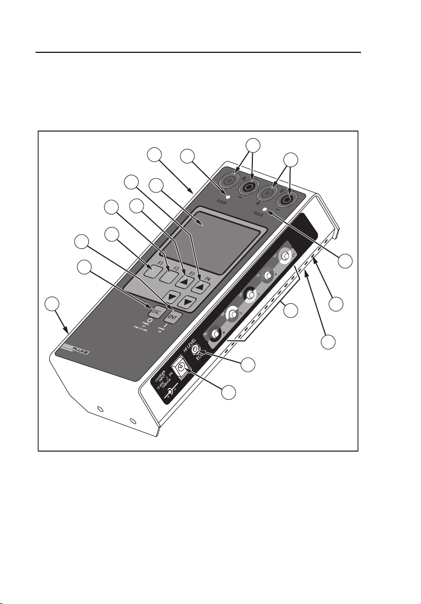
Instrument Familiarization
The Analyzer’s features and controls are shown in Figure 1-1 and described in
Table 1-2.
16
6
7
Biomedical
SIGMA PACE 1000
EXTERNALPACEMAKER ANALYZER
17
2
1
3
4
8
10
5
11
9
12
15
18
13
14
1-8
Figure 1-1. Analyzer Features and Controls
eyr056.eps
Page 23

Introduction and Specifications
Instrument Familiarization
Table 1-2. Analyzer Features and Controls
Number Description
Top Panel
LCD Readout (8 Lines X 21 Characters)
1
F4 / UP and DOWN Arrow Keys
2
F3 / UP and DOWN Arrow Keys
3
F2 Key
4
F1 Key
5
ENTER and POWER ON Key
6
ESCAPE and POWER OFF Key
7
Atrial Channel Sense Indicator (Yellow LED)
8
Atrial Channel Pacemaker Input Jacks (4 mm)
9
Red: Positive Black: Negative
Ventricular Channel Pacemaker Input Jacks (4 mm)
10
Red: Positive Black: Negative (Transvenous and
Transcutaneous)
1
Right Side Panel
11
12
13
14
15
16
17
18
Ventricular Channel Sense Indicator (Yellow LED)
Low Level ECG Output (Disposable Snap Compatible)
High Level ECG Output (Subminiature Phone Jack)
Charger / dc Power Supply Input Jack
Ventilation Slots
Left Side Panel
Load Current (Phantom Battery) Input Connector
RS-232 Serial Port
Bottom Panel
RESET Button
1-9
Page 24

SigmaPace 1000
Operators Manual
Abbreviations
The following list includes abbreviations used in this document.
A ampere
ANSI American National Standards Institute
AAMI
BLU blue (color)
BPM beats per minute
dB decibel
°C degrees Celsius (centigrade)
CQM Contact Quality Monitor
DMM digital multimeter
DUT device under test
EEPROM electrically erasable PROM
ECG electrocardiograph or electrocardiogram
ESU Electrosurgery Unit
EUT equipment under test
°F degrees Fahrenheit
GRA gray (color)
GRN green (color)
Hz hertz
Association for the Advancement of Medical
Instrumentation
in inch
J Joules
k kilo (10
kg kilogram
kHz kilohertz
3
)
1-10
Page 25

Introduction and Specifications
Abbreviations
kΩ kilohm
lb pound
LED light-emitting diode
LCD liquid crystal display
M meg(a) (106)
MHz megahertz
MΩ megohm
m meter
m milli (10
mA milliampere
mm millimeter
mV millivolt
p-p peak-to-peak
REM Return Electrode Monitor
-3
)
1
s second
YEL yellow (color)
µ micro (10-6)
µA microampere
µV microvolt
Ω ohm
1-11
Page 26

SigmaPace 1000
Operators Manual
General Specifications
Listed product specifications are subject to change.
Temperature
Operating.............................................................18 - 40 °C
Storage................................................................0 - 50 °C
Relative Humidity, Operating ...............................90 % max (non-condensing)
Altitude ...................................................................2000 m
Serial Port
Connector Type...................................................DB-9 (Male)
Baud Rates..........................................................2400, 9600, and 19200
Service Manual ......................................................2243314
Power Requirement
External Battery Charger / Power Supply
Input ................................................................90-264 V, 50/60 Hz
Output..............................................................15 V +/-5 %, 1500mA 100 to 240 V ac
Auto power off / sleep mode
Sleep Modes
Reset ...................................................................Analyzer reset button accessed via
Physical
Size .....................................................................8” X 4” X 2” (approx.) (203 mm X 101
Weight .................................................................2 lb (0.90 kg) approximate
50 / 60 Hz operation
bottom panel.
Sleep mode conditions.
mm X 50 mm)
Instrument Specifications
Modes of Operation
Manual
Remote (via standard RS-232 serial port)
User Interface
Display
LCD Readout...................................................21 characters X 8 lines
Pushbuttons
Eight keys........................................................F-1, F-2, F-3 (UP Arrow), F-4 (UP
1-12
Brightness / viewing angle adjustment
Arrow), 2 Down Arrows, ESCAPE, and
ENTER
Page 27

Introduction and Specifications
Instrument Specifications
1
Transcutaneous Pacemaker Tests
Output Pulse Measurement
Test Type ............................................................... Quantitative
Measurement Ranges
Output ................................................................. 4.0 mA to 9.99 mA
Accuracy......................................................... ±2 % of reading or ±50 µA (whichever
Rate .................................................................... 5.0 PPM to 99.9 PPM
Accuracy......................................................... ±0.5 % of reading or 0.3 PPM
Width................................................................... 1.00 mS to 9.99 mS
Accuracy......................................................... ±0.5 % of reading or 14 µS (whichever
Energy ................................................................ 1µJ to 999 µJ
Accuracy......................................................... ±5 % of reading / computation
10.0 mA to 99.9 mA
100 mA to 250 mA
is greater)
100 PPM to 300 PPM
(whichever is greater)
10.0 mS to 99.9 mS
is greater)
1 mJ to 999 mJ
1.00 J to 1.99 J
Demand Mode Test
Test Type ............................................................... Qualitative
Physiological Simulation
Selection ............................................................. Normal Sinus Rhythm (NSR)
Amplitude............................................................ (V
Mode of Operation
Underdrive .......................................................... NSR @ 85 % of measured pulse
Overdrive ............................................................ NSR @ 115 % of measured pulse
Auxiliary Control................................................... The under / overdrive NSR simulations
1-13
generates the complete P-QRS-T
complex.
): 1.0 mV Lead I.
peak
interval / rate
interval / rate
can also be independently adjusted in
1 BPM increments.
Page 28

SigmaPace 1000
Operators Manual
Auxiliary Rate Range
Underdrive (minimum).........................................10 BPM
Overdrive (maximum)..........................................300 BPM
Active Outputs
Five lead ECG
Selected Ventricular Channel Test Load
High Level ECG Jack
This waveform is present on these three outputs.
Pacemaker Compatibility
Compatible Pulse Rates......................................30 to 200 PPM
Intended Type .....................................................External Transcutaneous VVI
(Ventricular Only Pace and Sense)
Asynchronous Mode Test
Test Type................................................................Qualitative
Physiological Simulation Selection
Selection..............................................................Normal Sinus Rhythm (NSR)
Amplitude (V
Rate (Interval)
Underdrive...........................................................NSR @ 85 % of measured pulse
Overdrive.............................................................NSR @ 115 % of measured pulse
Auxiliary Control ..................................................The under / overdrive NSR simulations
Auxiliary Rate Range
Underdrive (minimum).........................................10 BPM
Overdrive (maximum)..........................................300 BPM
Active Outputs
Five lead ECG
Selected Ventricular Channel Test Load
This waveform is present on both outputs.
Pacemaker Compatibility
Compatible Pulse Rates......................................30 to 200 PPM
Intended Type
External Transcutaneous
VOO (Asynchronous Ventricular Only Pace)
)..................................................1.0 mV Lead I
peak
generates the complete P-QRS-T
complex.
interval / rate
interval / rate
can be independently adjusted in 1
BPM increments.
1-14
Page 29

Introduction and Specifications
Instrument Specifications
1
Amplitude Sensitivity Test
Physiological Simulation
Selection ............................................................. +R-Wave, -S-Wave, and + T-Wave
Rate (Interval) ..................................................... Default: 120 BPM (500 mS)
Available Test Load
Selection(s)......................................................... (30) 50 Ω to 1550 Ω in 50 Ω steps
Waveform Selections.......................................... Square (SQU)
Amplitude
Range ................................................................. 0.05 mV
Accuracy ............................................................. ±5 % of setting
Resolution (Step Size)........................................ 0.05 mV steps from 0.05 mV
Width
Range ................................................................. 0.15 mS to 300 mS
Accuracy ............................................................. ±5 % of setting
Selection Count .................................................. 50
Resolution (Step Size)........................................ 0.05 mS steps from 0.15 mS to 0.95
Active Outputs
Five lead ECG
Selected Ventricular Channel Test Load
High Level ECG Jack
This waveform is present on these three outputs.
Pacemaker Compatibility
Compatible Pulse Rates ..................................... 30 to 200 PPM (Minimum)
Intended Pacemaker Type.................................. VVI (Ventricular Pace and Sense
Triangle (TRI)
Haversine (HSN)
SSQ
(50 V
peak
95 mV
mV
mS
1.0 mS steps from 1.0 mS to 19.0 mS
5.0 mS steps from 20 mS to 95.0 mS
25 mS steps from 100 mS to 300 mS
Only)
0.50 mV steps from 1.0
peak
to 5.0 mV
peak
) to 5.0 mV
peak
peak
peak
peak
to 0.
Noise Immunity Test
Waveform .............................................................. Sine Wave
Frequency.............................................................. 50 and 60 Hz
Accuracy................................................................ 0.5 Hz
1-15
Page 30

SigmaPace 1000
Operators Manual
Active Outputs
Selected Ventricular Channel Test load
Five lead ECG
Testload Amplitude Output
Ventricular Channel
Range..............................................................0.00 (OFF) to 10.0 mV
Accuracy..........................................................±5 % of setting
Resolution (Step Size).....................................0.50 mV
Pacer Load Range ..........................................(30) 50 Ω to 1550 Ω 1 %
Five Lead ECG Output
Range..................................................................0.00 (OFF) to 10.0 mV
Accuracy..............................................................±5 % of setting
Resolution (Step Size).........................................0.50 mV steps
Calibration Reference..........................................Lead I (RA to LA)
peak-to-peak
peak-to-peak
steps
peak-to-peak
Paced Refractory Period Test (PRP)
Range......................................................................20 mS to 500 mS
Accuracy..............................................................5 % of reading or 1 mS whichever is
Physiological Simulation
Selection..............................................................Triangle (TRI) Wave
Pulse Width .........................................................40 mS
Rate.....................................................................Single pulse: Interactive with applied
Amplitude...............................................................1.0 mV
Active Outputs .....................................................Five Lead ECG and selected
Pacemaker Compatibility
Compatible Pulse Rates......................................30 to 200 BPM
Intended Pacemaker Type ..................................VVI (Ventricular Pace and Sense
greater
pacemaker pulse activity in the
demand mode of operation.
Lead I
peak
ventricular channel test load This
waveform is present on both outputs.
Only)
Sensed Refractory Period Test (SRP)
Range......................................................................15 mS to 500 mS
Accuracy..............................................................±5 % of reading or ±1 mS, whichever
Physiological Simulation
Selection..............................................................Triangle (TRI) Wave
1-16
is greater
Page 31

Introduction and Specifications
Instrument Specifications
Pulse Width......................................................... 40 mS
Rate .................................................................... Double pulse: interactive with applied
Amplitude .............................................................. 1.0 m V
Active Outputs ...................................................... Five Lead ECG and selected
Pacemaker Compatibility
Compatible Pulse Rates ..................................... 30 to 200 BPM
Intended Pacemaker Type.................................. VVI (Ventricular Pace and Sense
pacemaker pulse activity in the
demand mode of operation.
Lead I
peak
ventricular channel test load. This
waveform is present on both outputs.
Only)
1
Transvenous Pacemaker Tests
Output Pulse Measurement
Test Type ............................................................... Quantitative
Display Formats
Single.................................................................. Atrial or Ventricular only
Dual .................................................................... Atrial and ventricular Channels
Measurement Ranges
Current................................................................ 0.05 mA to .999 mA* (Single Channel
Accuracy......................................................... 2 % of reading or ±50 µA (whichever is
Polarity Indicator ................................................. + or -
Rate .................................................................... 10 PPM to 99.9 PPM
Accuracy......................................................... 0.5 % or 0.3 PPM (whichever is
Width................................................................... 0.02 mS to .999 mS
Accuracy......................................................... 0.5 % or ±14 µS (whichever is greater)
Resolution........................................................... ±1 LSD or ±4 µS (whichever is
Only)
1.00 mA to 9.99 mA
10.0 mA to 30.0 mA
greater)
100 PPM to 999 PPM
greater)
1.00 mS to 9.99 mS
10.0 mS to 99.99 mS
greater)
1-17
Page 32

SigmaPace 1000
Operators Manual
Voltage ................................................................ 0.050 V
1.00 V
10.0 V
peak
to 9.99 V
peak
to 30.0 V
peak
to .999 V
peak
peak
peak
Accuracy..........................................................2 % of reading or 0.05 V
(whichever is greater)
Polarity Indicator..................................................+ or -
Energy .................................................................1 nJ to 999 nJ
1 µJ to 999 µJ – add “J” range
Accuracy..........................................................5 % of reading / computation
Displayed Data
Single: Amplitude - Current
Amplitude ........................................................Volts
Rate
Width
Energy
Dual: Atrial and Ventricular
Amplitude ........................................................Current
Rate
Width
AV Interval
AV Interval (Delay Time)
Test Type................................................................Quantitative
Measurement Ranges
10.0 mS to 99.9 mS
100 mS to 999 mS
Start / Stop Points
Start.................................................................Leading edge of atrial pacemaker
Stop .................................................................Leading edge of ventricular
Accuracy..............................................................1 % of reading / computation
pulse
pacemaker pulse
peak
Demand Mode Test
Test Type................................................................Qualitative
Channels
Single ..................................................................Atrial or Ventricular Only
Dual .....................................................................A+V
1-18
Page 33

Introduction and Specifications
Instrument Specifications
Simulation
Waveform ........................................................... SSQ
Atrial Channel ..................................................... Simulated P-wave
Width............................................................... 30 mS
Amplitude........................................................ 2.0 mV
Ventricular Channel ............................................ Simulated R-wave
Width............................................................... 40 mS
Amplitude........................................................ 2.5 mV
PR Interval .......................................................... 90 mS
Interactive Simulated Rates
Default Settings
Underdrive ...................................................... NSR @ 85 % of measured pulse
interval / rate
Overdrive ........................................................ NSR @ 115 % of measured pulse
interval / rate
Manual Control ............................................... The under / overdrive NSR simulations
can also be independently adjusted in
1 BPM increments.
Manual Rate Limits
Underdrive (minimum) .................................... 10 BPM
Overdrive (maximum) ..................................... 300 BPM
Active Outputs (Synchronous)
Selected Ventricular Channel Test Load
Selected Atrial Channel Test Load
Pacemaker Compatibility
Pulse Rate Range............................................... 30 to 200 PPM
Intended Pacemaker Types
VVI (Ventricular Channel Only: Pace and Sense)
AAI (Atrial Channel Only: Pace and Sense)
DDD (Both Channels: Pace and Sense)
peak
peak
1
Asynchronous Mode Test
Test Type ............................................................... Qualitative
Channels
Single.................................................................. Atrial or Ventricular Only
Dual .................................................................... A+V
1-19
Page 34

SigmaPace 1000
Operators Manual
Amplitude Sensitivity Test
Test Type................................................................Qualitative
Channels
Single Channel Operation Only (Atrial or Ventricular)
Atrial Channel
Test Type................................................................Quantitative
Physiological Simulation
Selection..............................................................+P-Wave
Rate.....................................................................30 to 120 BPM, Waveform delayed by
Active Outputs
Atrial Channel (4mm Banana Jacks) Only Test Load(s)
Available Selection(s)..........................................(3) 200 Ω, 500 Ω, and 1000 Ω ±1 %
Default Setting.....................................................500 Ω
Waveform Selections ..........................................Square (SQU)
Default Setting .......................................................SSQ
Amplitude
Pacer Load Selection ..........................................500 Ω (default)
Range..............................................................0.05 mV
Accuracy..........................................................±5 % of setting
Resolution (Step Size).....................................0.05 mV
Pacer Load Selection ..........................................200 Ω
Range..............................................................0.05 mV
Accuracy..........................................................±5 % of setting
Resolution (Step Size).....................................0.05 mV
80 % of the pulse-to-pulse
interval or 400 mS (whichever is
shorter).
Triangle (TRI)
Haversine (HSN)
Sine Square (SSQ)
Asymmetrical Triangle (ISO)
(Fixed Width 2 mS rise time / 13 mS
fall time)
0.95 mV
0.50 mV
50.0 mV
0.95 mV
0.50 mV
20.0 mV
(50 V
peak
steps from 0.05 mV
peak
peak
steps from 1.0 mV
peak
peak
(50 V
peak
steps from 0.05 mV
peak
peak
steps from 1.0 mV
peak
peak
) to 50.0 mV
peak
) to 20.0 mV
peak
peak
peak
peak
peak
peak
to
peak
to
to
to
1-20
Page 35

Introduction and Specifications
Instrument Specifications
Pacer Load Selection.......................................... 1000 Ω
Range ............................................................. 0.05 mV
peak
Accuracy......................................................... ±5 % of setting
Resolution (Step Size).................................... 0.05 mV
0.95 mV
0.50 mV
49.5 mV
05.0 mV
100 mV
Default Setting
Amplitude............................................................ 2.0 mV
Width
Range ................................................................. 0.15 mS to 95.0 mS
Accuracy ............................................................. ±5 % of setting
Selection Count .................................................. 50
Resolution (Step Size)........................................ 0.05 mS steps from 0.15 mS to 0.95
mS
1.0 mS steps from 1.0 mS to 19.0 mS
5.0 mS steps from 20 mS to 95.0 mS
Intended Pacemaker Types
AAI (Atrial Pace and Sense Only)
Compatible Pulse Rates ..................................... 30 to 200 PPM
(50 V
peak
steps from 0.05 mV
peak
peak
steps from 1.0 mV
peak
peak
steps from 50 mV
peak
peak
peak
) to 100 mV
peak
peak
peak
peak-to-
peak
to
to
1
to
Ventricular Channel
Physiological Simulation
Selection ............................................................. +R-Wave, -S-Wave, and + T-Wave
Rate .................................................................... 30 to 120 BPM, Delayed from the
Active Outputs ...................................................... Selected ventricular test load (4 mm
Waveform Selections
Square (SQU)
Triangle (TRI)
Haversine (HSN)
Sine Square (SSQ)
Asymmetrical Triangle (ISO)
(Fixed Width........................................................ 2 mS rise time / 13 mS fall time)
Default Setting .................................................... Sine Square (SSQ)
Test Load(s)
1-21
ventricular demand pacemaker
pulse by 80 % of the pulse-to-pulse
interval or 400 mS (whichever is
shorter).
Banana Jacks) only.
Page 36

SigmaPace 1000
Operators Manual
Available Selection(s)......................................(3) 200, 500 and 1000 Ω ±1 %
Default Setting.................................................500 Ω
Amplitude
Pacer Load Selection ..........................................500 Ω
Range..............................................................0.05 mV
Accuracy..........................................................±5 % of setting
Resolution .......................................................0.05 mV
0.95 mV
0.50 mV
50.0 mV
Pacer Load Selection ..........................................200 Ω
Range..............................................................0.05 mV
Accuracy..........................................................±5 % of setting
Resolution .......................................................0.05 mV
0.95 mV
0.50 mV
20.0 mV
Pacer Load Selection ..........................................1000 Ω
Range..............................................................0.05 mV
peak
Accuracy..........................................................±5 % of setting
Resolution .......................................................0.05 mV
0. 95 mV
0.50 mV
49.5 mV
05.0 mV
100 mV
Default Setting .......................................................2.5 mV
Width
Range..................................................................0.15 mS to 300 mS
Accuracy..............................................................±5 % of setting
Selection Count ...................................................58
Resolution (Step Size).........................................0.05 mS steps from 0.15 mS to 0.95
mS
1.0 mS steps from 1.0 mS to 19.0 mS
5.0 mS steps from 20 mS to 95.0 mS
25 mS steps from 100 mS to 300 mS
Intended Pacemaker Type(s)
VVI (Atrial Pace and Sense Only)
Compatible Pulse Rates......................................30 to 200 PPM
(50 V
peak
steps from 0.05 mV
peak
peak
steps from 1.0 mV
peak
peak
(50 V
peak
steps from 0.05 mV
peak
peak
steps from 1.0 mV
peak
peak
(50 V
peak
steps from 0.05 mV
peak
peak
steps from 1.0 mV
peak
peak
steps from 50 mV
peak
peak
peak
) to 50.0 mV
peak
) to 20.0 mV
peak
) to 100 mV
peak
peak
peak
peak
peak
peak
peak
to
peak
peak
to
peak-to-
peak
to
to
to
to
to
1-22
Page 37

Introduction and Specifications
Instrument Specifications
1
Noise Immunity Test
Test Type ............................................................... Qualitative
Channels
Single.................................................................. Atrial or Ventricular Only
Waveform .............................................................. Sine Wave
Frequency.............................................................. 50 and 60 Hz
Accuracy................................................................ 0.5 Hz
Active Output(s).................................................... Selected atrial and / or ventricular
Output Selections
Atrial Channel Only
Ventricular Channel Only
ECG Signal ............................................................ ECG Signal can be added to the
Amplitude
Pacer Load Selection.......................................... 500 Ω
Range ............................................................. 0.00 (OFF) to 100 mV
Accuracy......................................................... ±5 % of setting
Resolution....................................................... 5 mV
Pacer Load Selection.......................................... 200 Ω
Range ............................................................. 0.00 (OFF) to 40 mV
Accuracy......................................................... ±5 % of setting
Resolution....................................................... 5 mV
Pacer Load Selection.......................................... 1000 Ω
Range ............................................................. 0.00 (OFF) to 200 mV
Accuracy......................................................... ±5 % of setting
Resolution....................................................... 5 mV
channel test load
selected Channel
steps
peak-to-peak
steps
peak-to-peak
steps
peak-to-peak
peak-to-peak
peak-to-peak
peak-to-peak
Refractory Period Test (Atrial Channel)
Test Selections
Paced Refractory Period (PRP)
Sensed Refractory Period (SRP)
Period..................................................................... 20 to 500 mS
Accuracy................................................................ ±5 % of reading or ±1 mS whichever is
Resolution ............................................................. ±1 LSD
Display Format...................................................... 3 digits
1-23
greater
Page 38

SigmaPace 1000
Operators Manual
Physiological Simulation
Selection (Default)...............................................Single Channel Simulation (A)
Atrial Channel......................................................Simulated P-wave
Width ...................................................................1.0 mS
Amplitude ............................................................20.0 mV
Active Outputs .....................................................Atrial Channel (4 mm Banana Jacks)
Additional Waveform Selections
Square (SQU)
Triangle (TRI)
Haversine (HSN)
Sine Square (SSQ)
Asymmetrical Triangle (ISO) (Fixed Width 2 mS rise time / 13 mS fall time)
Amplitude
Range...................................................................05 mV
Accuracy..............................................................±5 % of setting
Resolution (Step Size).........................................0.05 mV
Width
Range..................................................................0.15 mS to 95.0 mS
Accuracy..............................................................±5 % of setting
Selection Count ...................................................50
Resolution (Step Size).........................................0.05 mS steps: 0.15 mS to 0.95 mS
Active Output.......................................................Atrial Channel (4 mm Banana Jacks)
Intended Pacemaker Types ................................AAI (Atrial Pace and Sense Only)
Compatible Pacemaker Rates.............................30 to 200 PPM
Available Test Load.............................................500 Ω ±1 %
Square Wave
peak
Only
mV
peak
0.50 mV
mV
peak
peak
(50 V
peak
peak
) to 50.0 mV
peak
steps: 0.05 mV
steps: 1.0 mV
peak
peak
to 49.5
1.0 mS steps: 1.0 mS to 19.0 mS
5.0 mS steps: 20 mS to 95.0 mS
Only
peak
to 0.95
Refractory Period Test (Ventricular Channel)
Test Selections
Paced Refractory Period (PRP)
Sensed Refractory Period (SRP)
Period .....................................................................20 to 500 mS
Accuracy ................................................................±5 % of reading or 1 mS whichever is
1-24
greater
Page 39

Introduction and Specifications
Instrument Specifications
Resolution ............................................................. ±1 LSD
Display Format...................................................... 3 digits
Physiological Simulation
Selection (Default) .............................................. Single Channel Simulation (V)
Ventricular Channel ............................................ Simulated R-wave
Width................................................................... 1.0 mS
Amplitude............................................................ 20 mV
Active Outputs .................................................... Ventricular Channel
Available Test Load(s)........................................ 500 Ω Only
Additional Waveform Selections
Square (SQU)
Triangle (TRI)
Haversine (HSN)
Sine Square (SSQ)
Asymmetrical Triangle (ISO) (Fixed Width2 mS rise time / 13 mS fall time)
Amplitude
Pacer Load Selection.......................................... 500 Ω
Range ............................................................. 0.05 mV
Accuracy......................................................... ±5 % of setting
Resolution (Step Size).................................... 0.05 mV
Default Setting ................................................ 20.0 mV
Width
Range ................................................................. 0.15 mS to 300 mS
Accuracy ............................................................. 5 % of setting
Selection Count .................................................. 58
Resolution (Step Size)........................................ 0.05 mS steps from 0.15 mS to
Default Setting (mS) ........................................... 30 mS
Intended Pacemaker Types................................ VVI (Ventricular Pace and Sense
Compatible Pacemaker Rates ............................ 20 to 200 PPM
Square Wave
peak
(4 mm Banana Jacks) Only
50.0 mV
0.95 mV
0.50 mV
50.0 mV
(50 V
peak
peak
steps from 0.05 mV
peak
peak
steps from 1.0 mV
peak
peak
peak
peak
) to
0.95 mS
1.0 mS steps from 1.0 mS to 19.0 mS
5.0 mS steps from 20 mS to 95.0 mS
25 mS steps from 100 mS to 300 mS
Only)
peak
peak
1
to
to
1-25
Page 40

SigmaPace 1000
Operators Manual
DC Leakage Current
Test Type................................................................Quantitative
Measurement Range .............................................00.1 µA to 99.9 µA
Input Polarity..........................................................Positive and Negative
Resolution ..............................................................1 LSD
Display Format.......................................................3 digits plus decimal point
Test Selections
Static ...................................................................Continuous measurement
Pacemaker Power ...............................................OFF
Input Configurations ............................................Atrial+ and Atrial-
Dynamic ..............................................................Gated measurement preceding the
Pacemaker Power ...............................................ON
Input Configurations ............................................Atrial+ and Atrial-
Ventricular+ and VentricularAtrial+ and Ventricular- (third internal
500 Ω test load)
delivered pacemaker pulse.
Ventricular+ and VentricularAtrial+ and Ventricular+ (third internal
500 Ω test load)
Current Drain Test
Test Type................................................................Quantitative
Measurement Ranges
DC Current ..........................................................0.100 mA to .999 mA
Polarity ................................................................Positive or Negative
Polarity Indicator..................................................+ or - symbol preceding the numeric
Resolution ...........................................................±1 LSD
Display Format ....................................................3 digits plus decimal point
Accuracy..............................................................±5 % of Reading 10 µA
Input DC Voltage
Nominal ...............................................................±9 Volts
Range..................................................................5.0 Volts to 10.5 Volts
Input Protection ...................................................Short-circuit protection
Protection Type ...................................................Internal in-line fast-acting fuse rated at
Selectable Testloads ...........................................200 Ω, 500 Ω, and 1000 Ω
1.00 mA to 9.99 mA
10.0 mA to 99.9 mA
value
½ Ampere.
1-26
Page 41

Introduction and Specifications
Instrument Specifications
1
Battery Test Fixture ............................................ Includes the 9 volt battery supply and
facilitates connection of Analyzer to
the recessed battery terminals within
the Medtronic 5388 and 5348
Temporary Pacemakers.
Long Term Test
Test Configuration................................................ Atrial Channel or Ventricular Channel
Pulse Count Range............................................... 999,999 (maximum)
Rate ........................................................................ 2 % to 20 % (10 % default)
Amplitude .............................................................. 2 % to 20 % (10 % default)
Test Time (max) .................................................... 999:59:59 (hhh:mm:ss)
Maximum error Count .......................................... 200
Test Termination................................................... Manual or when maximum error count
Testloads Selectable ............................................ 200 , 500 , or 1000
is sensed.
Interactive Pacer ECG Simulation
Simulates demand, continuous, non-capture, and non-function patient ECG
activity.
Additional user-selectable parameters
PR Interval .......................................................... 0.05 to 0.300 Seconds
Independent Capture / threshold ........................ 1 mA to 25 mA (1 mA steps) for each
pacemaker channel.
Available Testloads (500 Ω Default)
Atrial Channel
Selections ........................................................... 200 Ω, 500 Ω, or 1000 Ω
Accuracy ............................................................. ±1.0 % of selection
Power Rating ...................................................... 2 Watts
Ventricular Channel
Selections ........................................................... 200 Ω, 500 Ω, or 1000 Ω
Accuracy ............................................................. ±1.0 % of selection
Power Rating ...................................................... 2 Watts
Tracking .............................................................. Atrial and ventricular channel settings
1-27
are identical.
Page 42

SigmaPace 1000
Operators Manual
Accessories
Standard accessories and associated part numbers are listed in Table 1-3;
optional accessories and associated part numbers are listed in Tables 1-4
through 1-8.
Table 1-3. Standard Accessories
Description Part Number
Transvenous Test Lead Red (2 each) 2201166
Transvenous Test Lead Black (2 each) 2201153
9 V dc Load Test Cable 2392272
Operators Manual 2243306
PC Interface Cable Female DB-9 to Female DB-9 2392260
Nylon Carry Case 2392906
Universal-Input Battery Eliminator 2184298
Table 1-4. Pacemaker Disposable Electrode Adapters
Description
All Pacemaker Disposable Electrode Adapters
Physio-Control QUIK COMBO 2201095
Physio-Control QUIK PACE 2201088
Hewlett Packard CodeMaster 2201109
Marquette Medical Responder 2201111
MDE / MRL R2 / DAROX 2201127
Zoll NTP Series 2201130
Zoll PD and M-Series 2201148
Part Number
1-28
Page 43

Introduction and Specifications
Accessories
Table 1-5. Serial Cables
Description Part Number
1
PC Interface Cable
Female DB-9 to Female DB-9
medTester Serial Interface
Female DB-9 to Female DB-25
Table 1-6. Compatible Power Supply
Region of Operation Part Number
Universal Power Supply 15V (90 to 264 VAC) IEC320
C6 3-wire
USA / CAN Power Cord IEC320 C5 3-wire 2198724
United Kingdom (UK) Power Cord IEC320 C5 3-wire 2201428
European Power Cord IEC320 C5 3-wire (SCHUKO) 2201437
Australia Power Cord IEC320 C5 3-wire 2201443
Table 1-7. Disposable Transcutaneous Pacemaker Adapters
Device Manufacturer Model/Designation Part Number
Medtronic/Physio Control
QUIK COMBO
Medtronic/Physio Control
QUIK PACE
HP/Agilent Technologies
Codemaster/HeartStream XL Series
GE Medical/Marquette
Responder Series
MDE Medical Data Electronics
MRL Medical Research Laboratories R2/DAROX
Zoll Medical
NTP Series•
Zoll Medical
PD and M Series (Multi- Function)
2200962
2200102
2184298
2201095
2201088
2201109
2201111
2201127
2201130
2201148
1-29
Page 44

SigmaPace 1000
Operators Manual
Table 1-8. High-Level Output Cables
Description Part Number
Subminiature Phone Plug to BNC Cable
(Oscilloscope Application)
Subminiature Phone Plug to 3-Conductor
¼” Phone Plug Cable (AA-900)
2199932
2200116
1-30
Page 45

Chapter 2
Setup, Operation, and Maintenance
Contents Page
Setting Up the Analyzer............................................................... 2-3
Connecting External Transcutaneous Pacemakers................... 2-3
Connecting External Transvenous Pacemakers........................ 2-4
Load Test Cable Connector...................................................... 2-4
RS-232 Serial Port Connector .................................................. 2-5
High Level ECG Output Jack................................................... 2-5
Ventilation................................................................................ 2-5
Power Up Sequence ..................................................................... 2-5
Transcutaneous Pacemaker Testing ............................................. 2-7
Transvenous Pacemaker Testing.................................................. 2-7
Utility Functions .......................................................................... 2-7
Maintenance................................................................................. 2-8
Avoiding Damage..................................................................... 2-8
Cleaning ................................................................................... 2-9
Service and Calibration................................................................ 2-9
Packing Instructions ................................................................. 2-10
Shipping ................................................................................... 2-10
2-1
Page 46

SigmaPace 1000
Operators Manual
2-2
Page 47

Setup, Operation, and Maintenance
Setting Up the Analyzer
2
Setting Up the Analyzer
The Analyzer utilizes an external plug-in universal power supply. It
automatically operates with applied main voltages rated from 83 to 264 V ac or
from the internal battery. No transformer taps, jumpers, or programming tabs
are required for Analyzer operation. The Analyzer is shipped from the factory
with the power supply configured for the desired (or specified) country or
region.
If your Analyzer is equipped with an incompatible power supply configuration,
contact the Fluke Biomedical Service Center regarding replacement/order
adjustment. Compatible power supplies and associated part numbers are listed
in the chapter “Introduction and Specifications.”
Set up the Analyzer for initial operation by plugging in the power supply plug
into the CHARGER INPUT located on the right side panel of the Analyzer.
Connecting External Transcutaneous Pacemakers
To facilitate the safe and convenient connection of the transcutaneous
pacemaker to the Analyzer, optional disposable electrode adapters are
available from Fluke Biomedical and are compatible with most device
manufacturers. These adapters connect the external pacemaker to the 4 mm
safety banana receptacle/jacks located on the Analyzer top panel and are listed,
with their Fluke part numbers, in the chapter “Introduction and
Specifications.”
W X Warning
To avoid injury to a patient, do not connect the Analyzer to
a patient or equipment connected to a patient. The
Analyzer is intended for equipment evaluation only and
should never be used in diagnostics, treatment or in any
other capacity where the Analyzer would come in contact
with a patient.
Refer to the latest Fluke Biomedical price list for availability of optional
electrode adapters.
2-3
Page 48

SigmaPace 1000
Operators Manual
Note
If desired, you may fabricate your own adapter cables by using
comparable general-purpose test leads with 4 mm safety (male)
banana plugs terminated with the requisite brand/designated
electrode connector.
Connecting External Transvenous Pacemakers
Two identical pairs of transvenous pacemaker test leads are supplied as
standard accessories with the Analyzer. These test leads are color-coded RED
(Part Number 2201166) and BLACK (Part Number 2201153) for connection
to the 4 mm safety banana receptacle/jacks located on the Analyzer top panel.
To securely connect the external transvenous pacemaker to the Analyzer, these
test leads incorporate 0.08” diameter pin probes compatible with external
transvenous pacemaker output jacks/terminals.
Use these test leads to connect the output of the transvenous single-channel
(atrial or ventricular) or dual-channel (atrial and ventricular) external
pacemaker to the SigmaPace 1000.
W X Warning
To avoid injury to a patient, do not connect the Analyzer to
a patient or equipment connected to a patient. The
Analyzer is intended for equipment evaluation only and
should never be used in diagnostics, treatment or in any
other capacity where the Analyzer would come in contact
with a patient.
Load Test Cable Connector
The load test cable plugs directly into the Analyzer left side panel connector
marked CURRENT DRAIN TEST. This standard accessory cable contains a
nine-volt battery to power the external pacemaker.
Note
A 0.5 Amp (FAST-BLO) fuse protects the load test metering circuitry
from an accidental short circuit or overload.
2-4
Page 49

Setup, Operation, and Maintenance
Power Up Sequence
2
RS-232 Serial Port Connector
The RS-232 serial port is used to connect the Analyzer to a controller for
remote operation. Refer to “Instrument Familiarity” for the location of this
connector and to the “Remote Operation” chapter for instructions on how to
operate the Analyzer remotely.
High Level ECG Output Jack
From the right-side panel, you can connect the high-level ECG output to a
compatible oscilloscope, slave monitor, or to the Armstrong Medical Industries
VIDEO ADAPTER RhythmSim™ 900 TV Interface Model AA-900. Use the
high-level output cables listed in the chapter “Introduction and Specifications.”
Ventilation
Heat generated during use is dissipated through ventilation slots on both the
left and right side panels.
W Caution
To avoid heat buildup damage to the Analyzer, do not
block the ventilation slots during use or while the
instrument is charging.
Power Up Sequence
Take the following steps to power up the Analyzer.
1. Press and release the ENT / POWER ON key, located on the Analyzer
top panel. The LCD momentarily displays the following screen.
2-5
Page 50

SigmaPace 1000
Operators Manual
F1 F2 F3 F4
The LCD then advances to the Select external pacemaker type
screen:
F1 F2 F3 F4
2-6
eyr008.eps
eyr001.eps
Page 51

Setup, Operation, and Maintenance
Transcutaneous Pacemaker Testing
2. From this screen, you can select one of the following options:
• F1 NONINV to begin Non-Invasive (transcutaneous) external
pacemaker testing.
• F2 INV to begin Invasive (transvenous) external pacemaker testing.
• F4 UTIL to access the Utility menu.
Note
Use the ESC or POWER OFF key during operation to return to
previous screens.
2
Transcutaneous Pacemaker Testing
See the “Transcutaneous Pacemaker Testing” chapter for test options and
specific directions.
Transvenous Pacemaker Testing
See the “Transvenous Pacemaker Testing” chapter for test options and specific
directions.
Utility Functions
To access the utility functions, do the following:
1. From the Select external pacemaker type screen, press F4 UTIL.
The UTILITY screen displays:
2-7
Page 52

SigmaPace 1000
Operators Manual
F1 F2 F3 F4
eyr057.eps
1. Press F1 VIEW ANGLE to adjust the viewing angle.
2. Press F2 COM PORT to select baud rate.
3. Press F3 BATT to view battery voltage and charging status.
4. Press F4 DIAG TEST to select calibration and display test functions.
Maintenance
The Analyzer requires little maintenance or special care; however, it is a
calibrated measuring instrument and should be treated as such. The following
describes how to maintain the Analyzer and the method of company support.
Avoiding Damage
Do not drop the instrument or subject it to any mechanical abuse that could
cause a shift in the calibrated settings.
2-8
Page 53

Setup, Operation, and Maintenance
Service and Calibration
W Caution
To avoid damage to the Analyzer or adverse affects on its
performance, do not expose the system to temperature
extremes. Ambient temperatures should remain between
18 and 40 °C. System performance may be adversely
affected if temperatures fluctuate above or below this
range.
2
Cleaning
Clean the exterior of the Analyzer occasionally with a cloth dampened with a
mild detergent solution. Take care to keep liquids out of the interior of the
unit.
W Caution
To avoid damage to the Analyzer or adverse affects on its
performance, clean it only by gently wiping down with a
clean, lint-free cloth dampened with a mild detergent
solution. Do not immerse the unit.
Carefully wipe down the cables and inspect them for damage and deterioration
of the insulation. Check the cable connections for integrity of the cable clamp
and strain relief.
Service and Calibration
If your new Analyzer fails to operate successfully, please contact the Fluke
Biomedical Service Center immediately, as indicated under “Warranty and
Product Support.”
W Caution
To avoid damage to the Analyzer or adverse affects on its
performance, allow only qualified technical personnel to
service the Analyzer.
Calibration of the Analyzer by an authorized Fluke Biomedical Service Center
is recommended. Fluke Biomedical Service Centers have the appropriate tools
and procedures for performing calibrations as well as factory-authorized
updates.
2-9
Page 54

SigmaPace 1000
Operators Manual
International customers should contact their Fluke Biomedical dealers for
service/product support.
To obtain the name of your local dealer or service center, contact Fluke
Biomedical as indicated under “Return Procedures, Repair and calibration.”
Packing Instructions
If calibration or repairs are required, return the Analyzer to the factory or the
nearest service center.
1. Before returning the Analyzer for factory service, contact the Fluke
Biomedical Service Center for a required Return Authorization Number.
2. Provide the following information:
• The Analyzer serial number
• The specific steps that reproduce your problem
• A daytime phone number
• Your name/company
• A fax number (if available)
3. Pack the instrument carefully, using the original packing materials. If the
original packing materials are not available, refer to “Return Procedures”
for a list of preferred materials or contact Fluke Biomedical for
replacement packing. Failure to pack the instrument properly could void
your warranty.
Shipping
4. Place the Return Authorization Number in a prominent place on the
outside of the packing box, and refer to the number in any correspondence
with Fluke Biomedical Service.
5. Enclose your return address and Return Authorization Number.
6. Insure the unit for full retail value and ship to the nearest Fluke
Biomedical service center.
2-10
Page 55

Chapter 3
Transcutaneous Pacemaker Testing
Contents Page
Test Options................................................................................. 3-3
Output....................................................................................... 3-4
Demand Mode .......................................................................... 3-5
Asynchronous Mode................................................................. 3-5
Amplitude Sensitivity............................................................... 3-5
Line Frequency / Noise Immunity............................................ 3-6
Refractory Period ..................................................................... 3-6
Paced Refractory Period (PRP)............................................. 3-6
Sensed Refractory Period (SRP)........................................... 3-7
Long Term Test........................................................................ 3-8
Interactive Pacemaker / ECG Simulation................................. 3-9
Simulated ECG Rate............................................................. 3-9
Adjustable Threshold Level.................................................. 3-9
Operational Modes ................................................................... 3-9
Continuous............................................................................ 3-9
Non-Capture ......................................................................... 3-9
Non-Function........................................................................ 3-10
Setup and Testing......................................................................... 3-10
Output....................................................................................... 3-12
Demand Mode Pacemaker’s Interaction with ECG Signal....... 3-14
Continuous Mode Pacemaker’s Interaction with ECG Signal.. 3-15
Demand Mode Pacemaker’s Ability to Sense ECG Activity ... 3-17
Amplitude of ECG Signal for Demand Mode Pacemaker........ 3-20
Pacemaker’s Ability to Filter Line Noise................................. 3-23
Purpose of the ECG Simulation Test........................................ 3-26
Long Term Tests ...................................................................... 3-27
3-1
Page 56

SigmaPace 1000
Operators Manual
3-2
Page 57

Transcutaneous Pacemaker Testing
Test Options
3
Test Options
The scheme for transcutaneous pacemaker testing is shown in Figure 3-1. The
specified (or default) test load is pre-selected with each algorithm. If desired,
you can easily select any test load (50 Ω to 1550 Ω in 50 Ω steps) with each
measurement algorithm.
Ensure that you select a test load within the device manufacturer’s specified
operational range. Device-specific measurement algorithms are selectable for
the following list of manufacturers:
• Physio-Control Lifepak Series (50 Ω)
• HP / Agilent Codemaster (400 Ω)
• GE / Marquette Responder Series (300 Ω)
• Medical Data Electronics (600 Ω)
• Medical Research Laboratories (500 Ω)
• Zoll Medical PD-Series (1000 Ω)
• Zoll Medical M-Series (100 Ω)
Tests requiring ECG simulation have three available active outputs:
• Low Level (2): 5 Lead: RL / N, RA / R, LA / L, LL / F, and V1 / C1
Transthoracic: Across the selected ventricular test load
• High Level (1): Output Amplitude tracks low level Lead I (1000:1)
+ / - 5.0V-peak maximum amplitude
Connector Type: Subminiature Phone Jack
3-3
Page 58
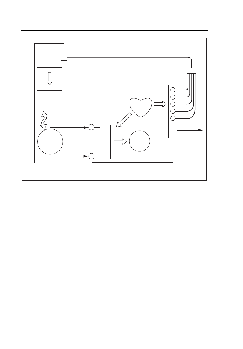
SigmaPace 1000
Operators Manual
ECG
Monitor
ECG
Sensing
& Pacer
ECG
V1/C1
LL/F
LA/L
RA/R
RL/N
L
O
A
M
High Level
Output
D
S
Transcutaneous
Pacemaker
SIGMAPACE 1000
External Pacemaker Analyzer
Figure 3-1. Scheme for Testing Transcutaneous Pacemakers
Output
The Analyzer measures the output of the transcutaneous pacemaker and
displays the following parameters:
• Pulse Amplitude (milliamperes)
• Pulse Rate (pulses per minute
• Pulse Width (milliseconds)
• Pulse Energy (joules)
eyr002.eps
3-4
Page 59

Transcutaneous Pacemaker Testing
Test Options
3
Demand Mode
This qualitative test verifies the demand mode pacemaker’s ability to interact
with a simulated ECG signal. The Analyzer first measures the pacemaker’s
applied pulse rate then computes “underdrive” and “overdrive” rates for the
simulated ECG signal. Initially, the underdrive rate is 90 % of the applied
pacemaker rate and the overdrive rate is 110 % of the applied pacemaker rate.
When testing the pacemaker, operating in the demand mode, output should be
active (ON) with the underdrive ECG signal and then inhibited (OFF) when
the overdrive ECG signal is selected. The rates of these underdrive and
overdrive ECG signals can be adjusted across a wide physiological range using
the Analyzer top panel controls.
Asynchronous Mode
This qualitative test verifies the continuous (or non-demand) mode
pacemaker’s ability to interact with a simulated ECG signal. The Analyzer
first measures the pacemaker’s applied pulse rate then computes underdrive
and overdrive rates for the simulated ECG signal. Initially, the underdrive rate
is 90 % of the applied pacemaker rate and the overdrive rate is 110 % of the
applied pacemaker rate.
When testing the attached pacemaker, operating in the continuous (or nondemand) mode, output should be active (ON) when either the underdrive ECG
signal or overdrive ECG signal is selected. The rates of these underdrive and
overdrive ECG signals can be adjusted across a wide physiological range by
the user.
Amplitude Sensitivity
This quantitative test determines the amplitude of the simulated ECG signal
required by the demand mode pacemaker. The amplitude of the simulated
ECG signal is increased in very small steps until the pacemaker senses it and
inhibits the output pulse.
3-5
Page 60

SigmaPace 1000
Operators Manual
Line Frequency / Noise Immunity
This qualitative test verifies the pacemaker’s ability to filter line frequency
noise at either 50 or 60 Hz and sense a simultaneously applied simulated ECG
signal. The user can change the amplitude of the line frequency noise, while
the simulated ECG signal amplitude is fixed.
Refractory Period
These two related qualitative tests determine the demand mode pacemaker’s
ability to sense ECG activity immediately following either a paced event
(PRP) or sensed ECG event (SRP).
Paced Refractory Period (PRP)
The Analyzer first measures the pacemaker’s applied pulse rate, and then
generates a simulated ECG signal within the expected PRP interval. See
Figure 3-2. This coupling interval is slowly extended until the simulated ECG
signal falls outside the PRP. The signal is then sensed by the pacemaker,
causing the escape interval to reset. The result is a longer pacing pulse
interval.
3-6
Page 61

Transcutaneous Pacemaker Testing
Test Options
Pacing Rate
Interv al
@ 8 0 BPM=750 mS
3
PRP
Cardiac Test Pu lse
Pacing Rate
Interv al
Reset>750 mS
PRP
"Sensed" Cardiac Test Pu ls e
Figure 3-2. Paced Refractory Period
eyr003.eps
Sensed Refractory Period (SRP)
The Analyzer then generates a second simulated ECG signal immediately
trailing the first simulated ECG signal used to determine the PRP. See Figure
3-3. This coupling interval is slowly extended until the simulated ECG signal
falls outside the PRP. The signal is then sensed by the pacemaker, causing the
escape interval to reset. The result is a longer pacing pulse interval.
3-7
Page 62

SigmaPace 1000
Operators Manual
Pacing Rate
Interv al
Reset > 750 mS
PRP
"S ens ed" Cardiac
Test Puls e # 1
SRP
Pacing Rate
Interval
Reset (2 X)
PRP
"S ens ed" Cardiac
Test Puls e # 1
"S ens ed" Cardiac
Test Puls e # 2
SRP
eyr004.eps
Figure 3-3. Sensed Refractory Period
Long Term Test
The overall stability of the pacemaker’s pulse rate and amplitude are
monitored continuously over an extended time period. Each measured pulse is
compared to factory preset limits of 10 % for both monitored variables. Test
limits are adjustable by the user.
3-8
Page 63

Transcutaneous Pacemaker Testing
Test Options
Upon completion of the desired long-term test duration, the user can review
pacemaker output pulses falling outside these test limits.
3
Interactive Pacemaker / ECG Simulation
The pacemaker responds to a wide range of simulated ECG signals using the
Analyzer test feature. Several variables are user selectable to best simulate
actual “real life” conditions.
Simulated ECG Rate
The Analyzer outputs either asystole or a normal sinus rhythm (NSR) at rates
covering the bradycardia, normal, and tachycardia range.
Adjustable Threshold Level
When the pacemaker output current exceeds the threshold amplitude setting (in
milliamperes), the Analyzer generates a simulated ventricular “paced” beat.
The pacemaker output current level required to effect “ventricular capture” is
selectable by the user.
Operational Modes
Three simulated operational modes are available in the Analyzer
Continuous
The user selects a rate, and the Analyzer generates a simulated ECG signal.
The threshold interaction with the pacemaker is observed. No normal sinus
rhythm (NSR) output is available in this operational mode.
Non-Capture
The Analyzer operates in “continuous mode”. However, every 8th expected
“ventricular capture” event is skipped. No normal sinus rhythm (NSR) output
is available in this operational mode.
3-9
Page 64

SigmaPace 1000
Operators Manual
Non-Function
The Analyzer operates in “continuous mode” without “ventricular capture”
events occurring. No normal sinus rhythm (NSR) output is available in this
operational mode.
Setup and Testing
The following describes how to set up and test a transcutaneous pacemaker.
1. Start from the Select external pacemaker type screen.
F1 F2 F3 F4
eyr009.eps
2. Press F1 NONINV to begin Non-Invasive (transcutaneous) pacemaker
testing.
3-10
Page 65

Transcutaneous Pacemaker Testing
Setup and Testing
F1 F2 F3 F4
3
3. Press the F3 PHYS-CTL BRAND UP or DOWN arrow key to select
instrument Brand / Model. The test load specified for each Brand / Model
selection is automatically selected.
4. Press the F4 UP or DOWN arrow key to select the load. Test loads are
available from 50 Ω to 1550 Ω in 50 Ω increments.
5. Press F1 NEXT to advance the display to the SELECT TEST menu.
There are eight Non-Invasive tests.
F1 F2 F3 F4
6. Press the F4 >>> UP arrow key to advance to the next screen and to see
more available tests.
eyr010.eps
eyr011.eps
3-11
Page 66

SigmaPace 1000
Operators Manual
F1 F2 F3 F4
F1 F2 F3 F4
7. Press ESC to return to previous menu(s).
Output
The following test measures the output of the transcutaneous pacemaker.
F1 F2 F3 F4
eyr012.eps
eyr013.eps
eyr014.eps
1. From the SELECT TEST menu, press F1 PULSE OUTPUT.
3-12
Page 67

Transcutaneous Pacemaker Testing
Setup and Testing
F1 F2 F3 F4
3
2. Press the F4 LOAD UP or DOWN arrow key to select the desired load.
3. Press F1 HOLD to advance the screen:
F1 F2 F3 F4
4. Press F4 XMIT DATA to transmit data through the serial port.
5. Press F1 RELEASE to release the hold and return to the HOLD screen.
6. Press ESC to return to previous menu(s).
eyr015.eps
eyr016.eps
3-13
Page 68

SigmaPace 1000
Operators Manual
Demand Mode Pacemaker’s Interaction with ECG
Signal
The following test verifies the demand mode pacemaker’s ability to interact
with a simulated ECG signal.
F1 F2 F3 F4
1. From the SELECT TEST menu, press F2 DMAND MODE.
F1 F2 F3 F4
2. Press the F4 UP or DOWN arrow key to select the desired load.
eyr014.eps
eyr058.eps
3. Press F1 START to advance the screen and start the test.
3-14
Page 69

Transcutaneous Pacemaker Testing
Setup and Testing
F1 F2 F3 F4
3
4. Press F2 SELECT DRIVE< to toggle between the Overdrive and
Underdrive BPM rates.
5. Once a rate is selected, press F4 DRIVE RATE BPM UP or DOWN
arrow key to adjust that rate.
6. Press ESC to return to previous menu(s).
eyr017.eps
Continuous Mode Pacemaker’s Interaction with ECG
Signal
The following test verifies the continuous (or non-demand) pacemaker’s
ability to interact with a simulated ECG signal.
F1 F2 F3 F4
eyr014.eps
3-15
Page 70

SigmaPace 1000
Operators Manual
1. From the SELECT TEST menu, press F3 ASYNC MODE.
F1 F2 F3 F4
2. Press the F4 LOAD UP or DOWN arrow key to select the load.
3. Press F1 START to advance the screen and start the test.
3-16
eyr059.eps
Page 71

Transcutaneous Pacemaker Testing
Setup and Testing
F1 F2 F3 F4
3
4. Press F2 SELECT DRIVE< to toggle between the Overdrive and
Underdrive BPM rates.
5. Once a rate is selected, press F4 DRIVE RATE BPM UP or DOWN
arrow key to adjust that rate.
6. Press ESC to return to previous menu(s).
eyr018.eps
Demand Mode Pacemaker’s Ability to Sense ECG
Activity
The two following, related tests, PRP and SRP, determine the demand mode
pacemaker’s ability to sense ECG activity immediately following either a
paced event (PRP) or a sensed ECG event (SRP).
Note
A transcutaneous pacemaker must be set to Demand operation for
these tests.
3-17
Page 72

SigmaPace 1000
Operators Manual
F1 F2 F3 F4
1. From the SELECT TEST menu, press F1 REFRCT DEMAND.
F1 F2 F3 F4
2. Press F4 LOAD UP or DOWN arrow key to select the load.
eyr012.eps
eyr060.eps
3. Press F1 START to advance screen and start the test.
3-18
Page 73

Transcutaneous Pacemaker Testing
Setup and Testing
F1 F2 F3 F4
3
After the calculations are complete, the following screen appears.
F1 F2 F3 F4
eyr020.eps
eyr021.eps
3-19
Page 74

SigmaPace 1000
Operators Manual
4. Press F1 RESTART to restart the test.
5. Press F4 XMIT DATA to transmit data.
6. Press ESC to return to previous menu(s).
Amplitude of ECG Signal for Demand Mode Pacemaker
The following test determines the amplitude of the simulated ECG signal
required by the demand mode pacemaker.
F1 F2 F3 F4
1. From the SELECT TEST menu, press F2 SENSE AMP.
F1 F2 F3 F4
eyr012.eps
eyr062.eps
3-20
Page 75

Transcutaneous Pacemaker Testing
Setup and Testing
2. Press the F4 LOAD UP or DOWN arrow key to select the load.
3. Press F1 NEXT to advance the screen for waveform selection.
F1 F2 F3 F4
3
4. Press F3 UP or DOWN arrow key to select waveform type.
5. Press F4 UP or DOWN arrow key to select waveform width.
6. Press F1 NEXT for amplitude and polarity selection.
3-21
eyr062.eps
Page 76

SigmaPace 1000
Operators Manual
F1 F2 F3 F4
eyr063.eps
7. Press F3 POLARITY UP or DOWN arrow key to toggle the polarity.
8. Press F4 AMPLITUDE to adjust amplitude.
9. Press F1 START to initiate the test.
3-22
Page 77
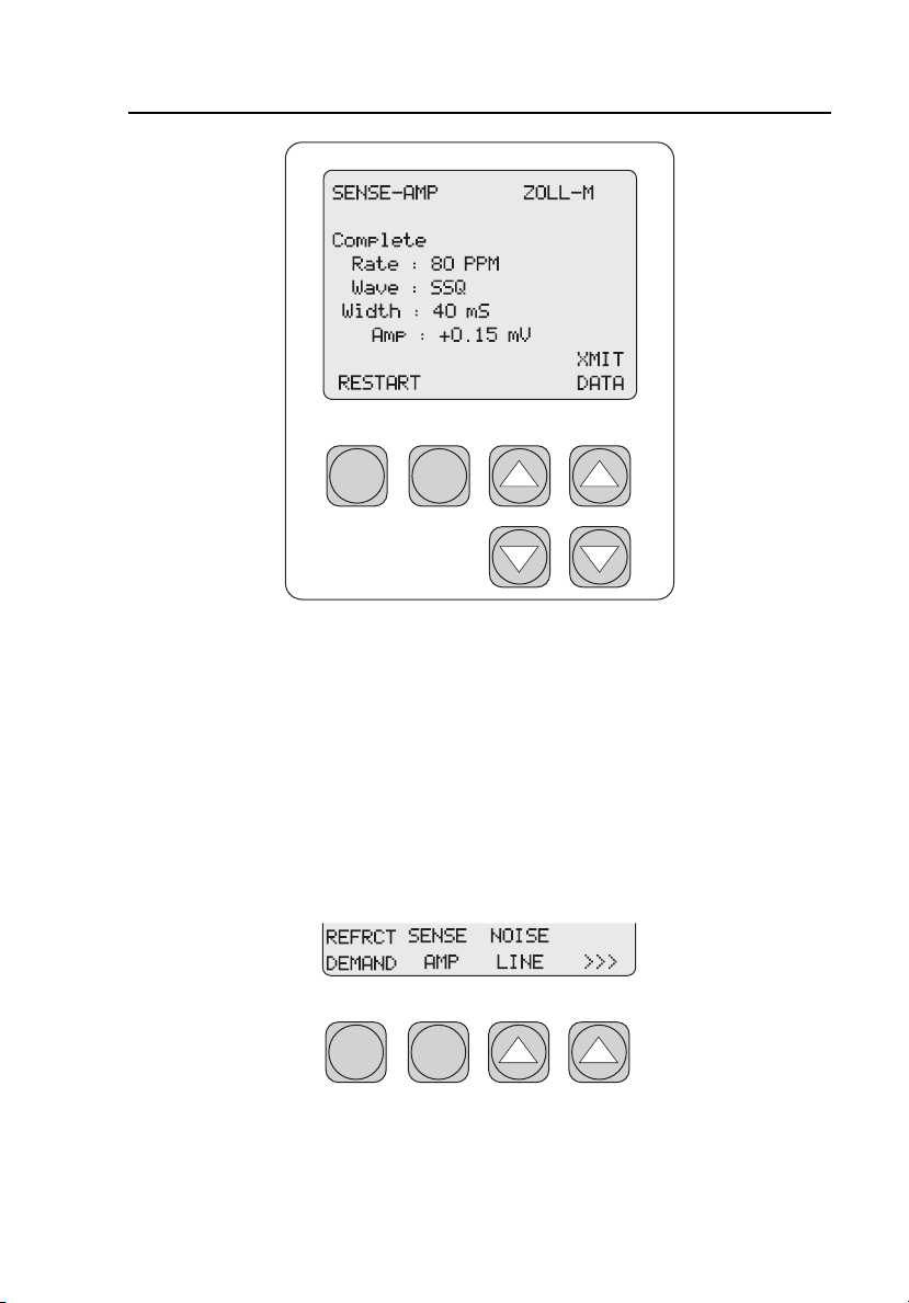
Transcutaneous Pacemaker Testing
Setup and Testing
F1 F2 F3 F4
3
10. Press F4 XMIT DATA to transmit data.
11. Press F1 RESTART to begin the test again.
12. Press ESC to return to previous menu(s).
eyr022.eps
Pacemaker’s Ability to Filter Line Noise
The following test measures a pacemaker’s ability to filter line noise at either
50 or 60 Hz.
F1 F2 F3 F4
1. From the SELECT TEST menu, press F3 NOISE LINE.
eyr012.eps
3-23
Page 78

SigmaPace 1000
Operators Manual
F1 F2 F3 F4
2. Press F3 UP or DOWN arrow key select the line frequency.
3. Press F4 LOAD UP or DOWN arrow key to select the load.
4. Press F1 NEXT to advance the screen.
eyr064.eps
3-24
Page 79

Transcutaneous Pacemaker Testing
Setup and Testing
F1 F2 F3 F4
3
5. Press F3 ECG UP or DOWN arrow key to toggle the ECG function ON
or OFF.
6. Press F4 AMP UP or DOWN arrow key to adjust the amplitude of the
line frequency.
7. Press F1 HOLD to advance the screen.
eyr065.eps
3-25
Page 80

SigmaPace 1000
Operators Manual
F1 F2 F3 F4
eyr066.eps
8. Press F4 XMIT DATA to transmit data.
9. Press F1 RELEASE to release the hold and return to the HOLD screen.
10. Press ESC to return to previous menu(s).
Purpose of the ECG Simulation Test
This test lets the technician check external pacemakers for basic operation,
performance, and intermittent problems. Additionally, it is an excellent
training tool for clinical staff in the setup and use of external pacemakers.
F1 F2 F3 F4
1. From the SELECT TEST menu, press F1 ECG SIM.
eyr013.eps
3-26
Page 81

Transcutaneous Pacemaker Testing
Setup and Testing
F1 F2 F3 F4
3
2. Press F1 OUTPUT to toggle among four simulated operational modes:
• Demand
• Continuous
• Non-capture
• Non-function.
3. Press F3 THRESH UP or DOWN arrow key to adjust the threshold
amplitude.
4. Press F4 NSR RATE UP or DOWN arrow key to adjust the NSR rate.
Note
The NSR rate function is active only during the demand mode of
operation.
eyr025.eps
Long Term Tests
The overall stability of the pacemaker’s pulse rate and amplitude are
monitored continuously over an extended period of time. The user enters the
desired target values for these two parameters into the Analyzer. This program
3-27
Page 82

SigmaPace 1000
Operators Manual
flexibility allows the user to enter either the actual test pacemaker values or the
selected rate and amplitude settings.
Deviation values are independently selectable from 2 % to 20 % in 1 %
increments. The Analyzer compares these incoming pacer pulses to the target
values. When the long-term test is complete, output pulses from the
pacemaker that were not within the selected limits may be reviewed.
F1 F2 F3 F4
1. From the SELECT TEST menu, press F2 LONG TERM.
F1 F2 F3 F4
2. Press F2 RATE to toggle between pulse rate and amplitude. This
parameter works with the LIMIT parameter to assign limits to both.
eyr013.eps
eyr026.eps
3-28
Page 83

Transcutaneous Pacemaker Testing
Setup and Testing
3. For each, pulse rate and amplitude, press F3 LIMIT UP or DOWN arrow
key to select the limit value.
4. Press F4 LOAD UP or DOWN arrow key to select the load.
5. Press F1 NEXT to advance the screen.
F1 F2 F3 F4
3
6. Press F3 AMP UP or DOWN arrow key to adjust the amplitude.
7. Press F4 RATE UP or DOWN arrow key to adjust the rate.
Note
Target values for amplitude and rate must be entered for the test to
perform correctly.
8. Press F1 START to advance the screen and start the test.
3-29
eyr027.eps
Page 84

SigmaPace 1000
Operators Manual
F1 F2 F3 F4
9. Press F1 END to end the test.
F1 F2 F3 F4
eyr028.eps
eyr029.eps
3-30
Page 85

Transcutaneous Pacemaker Testing
Setup and Testing
10. Press F3 REVIEW UP or DOWN arrow key to view deviations falling
outside the selected deviation values for rate and amplitude.
Up to 200 deviations will be stored in the Analyzer memory. Any long
term test exceeding 200 deviations is automatically terminated. The pulse
width at the “out of limit” pacemaker pulse is also reported.
11. Press F4 XMIT to transmit data.
12. Press F1 RESTART to restart the test.
13. Press ESC to return to previous menu(s).
3
3-31
Page 86

SigmaPace 1000
Operators Manual
3-32 4-1
Page 87

Chapter 4
Transvenous Pacemaker Testing
Contents Page
Test Options................................................................................. 4-3
Output....................................................................................... 4-4
Demand Mode .......................................................................... 4-4
Asynchronous Mode................................................................. 4-4
Amplitude Sensitivity............................................................... 4-5
Line Frequency / Noise Immunity............................................ 4-5
Refractory Period ..................................................................... 4-5
Paced Refractory Period (PRP)............................................. 4-5
Sensed Refractory Period (SRP)........................................... 4-5
Interactive Pacemaker/ ECG Simulation.................................. 4-6
Simulated ECG Rate ................................................................ 4-6
PR Interval................................................................................ 4-6
Adjustable Threshold Level ..................................................... 4-6
Operational Modes ................................................................... 4-6
Continuous............................................................................ 4-6
Non-Capture ......................................................................... 4-7
Non-Function........................................................................ 4-7
DC Leakage.............................................................................. 4-7
Static Tests (Pacemaker Power OFF): .................................. 4-8
Dynamic Tests (Pacemaker Power ON): .............................. 4-9
Current Drain Test.................................................................... 4-9
Long Term Test........................................................................ 4-11
Setup and Testing......................................................................... 4-11
Output....................................................................................... 4-13
Demand Mode and Dual-channel (AV) ECG Signal................ 4-16
Continuous Mode and Dual-channel (AV) ECG Signal........... 4-18
Demand Mode Pacemaker’s Ability to Sense ECG Activity ... 4-20
Amplitude of ECG Signal for a Demand Mode Pacemaker ..... 4-23
Pacemaker’s Ability to Filter Line Noise................................. 4-28
DC Leak Test........................................................................ 4-31
DC Load Test........................................................................ 4-34
ECG Simulation Test............................................................ 4-36
Long Term Tests ...................................................................... 4-38
Page 88

SigmaPace 1000
Operators Manual
4-2
Page 89

Transvenous Pacemaker Testing
Test Options
4
Test Options
The scheme for transcutaneous pacemaker testing is shown in Figure 4-1.The
measurement algorithms, protocols, and default waveform selections are based
on the requirements published by Medtronic for their Model 5388 dual
chamber temporary (external) pacemaker. Waveform selections for other
brands and models of pacemakers are available in the Analyzer menus.
Typically, transvenous pacemaker measurements are specified at a test load
setting of 500 Ω, which is the Analyzer default setting. For most transvenous
pacemaker tests, two additional loads of 200 Ω and 1000 Ω are also available.
The test load resistance values track for both the atrial and ventricular
channels.
Atrial Channel
A+
L
O
A
D
A-
M
S
ECG
Sensing
& Pacer
V+
ECG
L
O
M
Ventricular
Channel
Transvenous
Pacemaker
A
D
V-
S
SIGMAPACE 1000
External Pacemaker Analyzer
Figure 4-1. Scheme for Testing Transvenous Pacemakers
V1/C1
LL/F
LA/L
RA/R
RL/N
High Level
Output
eyr005.eps
4-3
Page 90

SigmaPace 1000
Operators Manual
Output
The Analyzer measures the output of the transvenous pacemaker, and displays
the following parameters:
• Pulse Amplitude = milliamperes
• Pulse Rate = pulses per minute
• Pulse Width = milliseconds
• AV Delay = milliseconds
• Voltage = volts
• Energy = joules
To view these parameters, three choices are available from the menu: A+V
Channels, A Channel Only, and V Channel Only.
Demand Mode
Tests are performed simultaneously for both atrial and ventricular channels.
This qualitative test checks the demand mode pacemaker’s ability to interact
with a simulated dual-channel (AV) ECG signal. The Analyzer first measures
the pacemaker’s applied pulse rate, then computes “underdrive” and
“overdrive” rates for the simulated dual-channel (AV) ECG signal. Initially,
the underdrive rate is 90 % of the applied pacemaker rate, and the overdrive
rate is 110 % of the applied pacemaker rate. When testing the attached
pacemaker, operating in the demand mode, output should be active (ON) with
the underdrive ECG signal, and then inhibited (OFF) when the overdrive ECG
signal is selected. The rates of these underdrive and overdrive ECG signals
can be adjusted across a wide physiological range.
Asynchronous Mode
Tests are performed simultaneously for both atrial and ventricular channels.
This qualitative test checks the continuous (or non-demand) mode pacemaker’s
ability to interact with a simulated dual-channel (AV) ECG signal. The
Analyzer first measures the pacemaker’s applied pulse rate and then computes
“underdrive” and “overdrive” rates for the simulated ECG signal. Initially, the
underdrive rate is 90 % of the applied pacemaker rate and the overdrive rate is
110 % of the applied pacemaker rate. When testing the attached pacemaker,
operating in the continuous (or non-demand) mode, output should be active
4-4
Page 91

Transvenous Pacemaker Testing
Test Options
(ON) when either the underdrive ECG signal or overdrive ECG signal is
selected. The rates of these underdrive and overdrive ECG signals can be
adjusted across a wide physiological range by the user.
4
Amplitude Sensitivity
Tests are performed independently for the atrial and ventricular channels. This
quantitative test determines the required amplitude of the simulated ECG
signal to be detected by the demand-mode pacemaker. The amplitude of the
simulated ECG signal is increased in very small steps until the pacemaker
senses it and inhibits the output pulse.
Line Frequency / Noise Immunity
Tests are performed in two formats: atrial channel only and ventricular channel
only. This qualitative test checks the pacemaker’s ability to filter line
frequency noise at either 50 or 60 Hz, and sense a simultaneously applied
simulated ECG signal. The user can change the amplitude of both the line
frequency noise. The simulated ECG signal amplitude is fixed.
Refractory Period
Tests are performed independently for the atrial and ventricular channels.
These two related qualitative tests determine the demand mode pacemaker’s
ability to sense ECG activity immediately following either a paced event
(PRP) or sensed ECG event (SRP).
Paced Refractory Period (PRP)
The Analyzer first measures the pacemaker’s applied pulse rate, then generates
a simulated ECG signal within the expected PRP interval. This coupling
interval is slowly extended until the simulated ECG signal falls outside the
PRP at which time it is sensed by the pacemaker, resetting the escape interval,
resulting in a longer pacing pulse interval.
Sensed Refractory Period (SRP)
The Analyzer now generates a second simulated ECG signal immediately
trailing the first simulated ECG signal used to determine the PRP. This
4-5
Page 92

SigmaPace 1000
Operators Manual
coupling interval is slowly extended until the simulated ECG signal falls just
outside the SRP at which time it is sensed by the pacemaker, resetting the
escape interval, resulting in a longer pacing pulse interval.
Interactive Pacemaker/ ECG Simulation
Tests are performed simultaneously for both atrial and ventricular channels.
The response of the pacemaker to a wide range of simulated ECG signals is
demonstrated using this Analyzer test feature. Several variables are user
selectable to best simulate actual “real life” conditions.
Simulated ECG Rate
The Analyzer outputs either asystole or a normal sinus rhythm (NSR) at rates
covering the bradycardia, normal, and tachycardia range.
PR Interval
The PR interval of the above ECG waveform complex is also user-selectable.
Adjustable Threshold Level
When the measured pacemaker output current exceeds the threshold amplitude
setting (in milliamperes), the Analyzer outputs a simulated ventricular “paced”
beat. The pacemaker output current level required to effect “ventricular
capture” is selectable by the user.
Operational Modes
Three simulated operational modes are available in the Analyzer
Continuous
The user selects a rate, and the Analyzer generates a simulated ECG signal.
The threshold interaction with the pacemaker is observed.
4-6
Page 93

Transvenous Pacemaker Testing
Test Options
4
Non-Capture
The Analyzer operates in the above continuous mode. However, every 8th
expected ventricular capture event is skipped.
Non-Function
The Analyzer operates in the above continuous mode. However no ventricular
capture events occur.
DC Leakage
The integrity of the pacemaker’s final output stage is evaluated during these
leakage tests. See Figure 4-2. Over time, the pacemaker’s active and passive
electronic components can deteriorate and possibly couple dc voltage
potentials to its final output stage.
4-7
Page 94
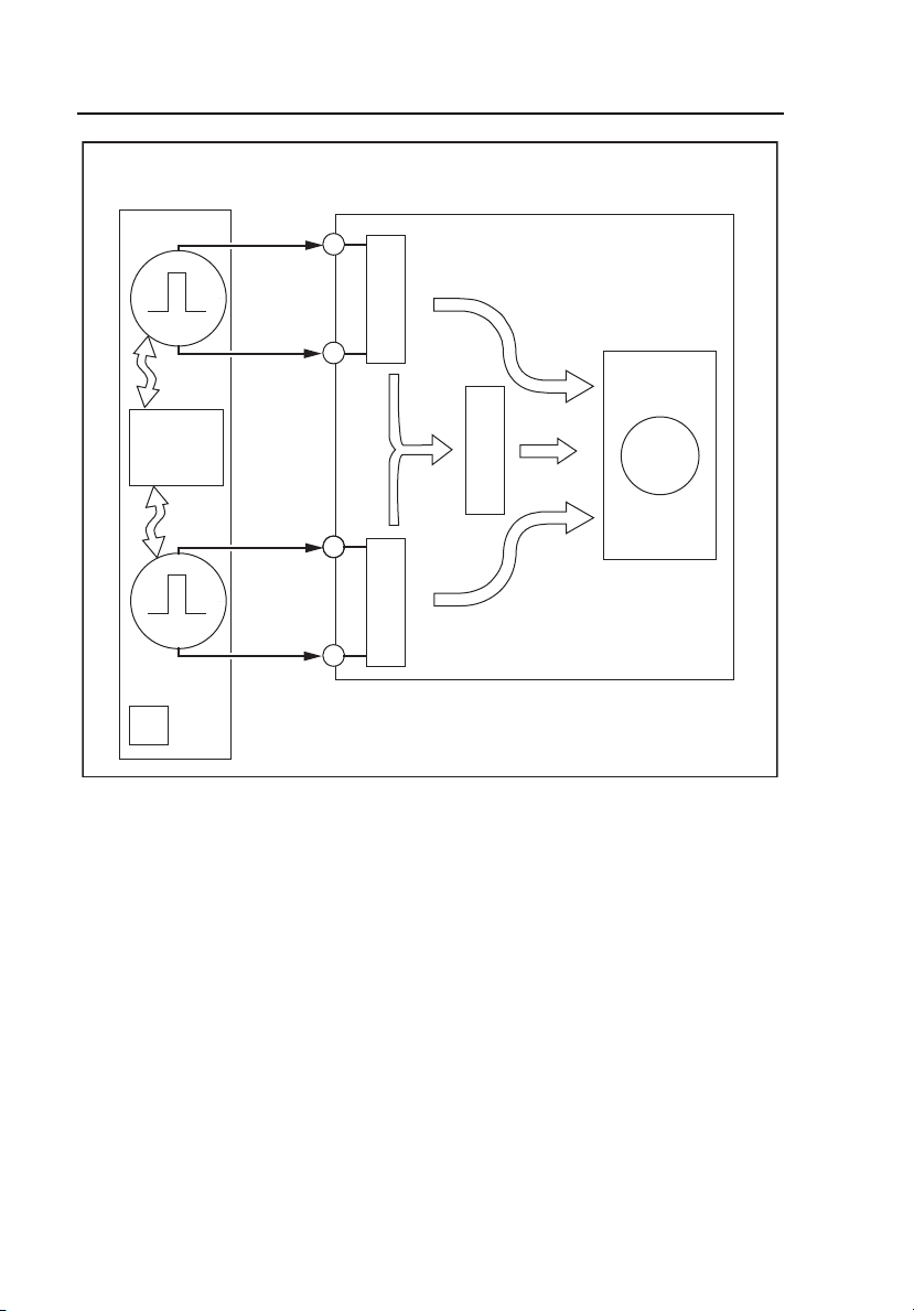
SigmaPace 1000
Operators Manual
Transvenous
Pacemaker
Atrial Channel
ECG
Sensing
& Pacer
Control
Ventricular
Channel
Power
ON/OFF
SIGMAPACE 1000
External Pacemaker Analyzer
L
A+
O
A
D
A-
S
L
A+
O
A
V+
D
L
V+
O
A
D
V-
S
Figure 4-2. DC Leakage Testing
Static &
Dynamic
M
DC
Leakage
eyr006.eps
Potentially harmful dc levels can be detected using the various test
configurations described below:
Static Tests (Pacemaker Power OFF):
These tests continuously measure dc leakage as follows:
• Atrial Channel: dc leakage across the atrial channel 500 Ω test load.
• Ventricular Channel: dc leakage across the ventricular channel 500 Ω
test load.
• AV Channel: dc leakage across an auxiliary 500 Ω test load
connected to the +atrial and +ventricular outputs.
4-8
Page 95

Transvenous Pacemaker Testing
Test Options
4
Dynamic Tests (Pacemaker Power ON):
These tests are triggered measurements of dc leakage, measured prior to the
specific output pulse as follows:
• Atrial Channel: dc leakage across the atrial channel 500 Ω test load.
• Ventricular Channel: dc leakage across the ventricular channel 500 Ω
test load.
• AV Channel: dc leakage across an auxiliary 500 Ω test load
connected to the +atrial and +ventricular outputs.
Note
Refer to the check out procedure for your specific pacemaker
regarding testing protocols and limits for these dc leakage tests.
Current Drain Test
This test measures the load current drawn by the pacemaker from a 9 volt
source. See Figure 4-3. A load test cable (Part # 2201074) is provided with
the Analyzer as a standard accessory to facilitate connections to the recessed
battery terminals of the Medtronic 5388 and 5348.
4-9
Page 96

SigmaPace 1000
Operators Manual
Transvenous
Pacemaker
Internal Battery
Compartment
Power
ON/OFF
SIGMAPACE 1000
External Pacemaker Analyzer
L
O
A
D
DC
Current
S
L
M
O
A
D
mA
S
+
-
9 VDC
Battery
Figure 4-3. Current Drain Test
Readings are made in three pacemaker operating modes:
• Pacemaker Power OFF
• Pacemaker Power ON and Display Backlight OFF
• Pacemaker Power ON and Display Backlight ON
4-10
eyr007.eps
Page 97

Transvenous Pacemaker Testing
Setup and Testing
Standard test leads or short jumpers can be used to make connections on other
brands and models of pacemakers.
4
Long Term Test
Tests are performed for only one channel at a time. The overall stability of the
pacemaker’s pulse rate and amplitude are monitored continuously over an
extended time period. The user can independently input desired test limits for
amplitude and rate (2-20) or use the factory default 10 % limits. Upon
completion of the desired long-term test duration, the user can review
pacemaker output pulses falling outside these test limits.
Setup and Testing
The following describes how to set up and test a transvenous pacemaker.
F1 F2 F3 F4
1. From the Select external pacemaker type screen, press F2 INV to
begin Invasive (transvenous) pacemaker testing.
4-11
eyr001.eps
Page 98

SigmaPace 1000
Operators Manual
F1 F2 F3 F4
eyr031.eps
2. Press the F4 LOAD UP or DOWN arrow key to select the desired load.
Test loads are available at 200, 500, and 1000 Ohms. Both atrial and
ventricular test loads are set simultaneously to the selected value.
3. Press F1 NEXT to advance the display to the SELECT TEST menu.
There are ten available Invasive tests.
F1 F2 F3 F4
eyr032.eps
4. Use the F4 >>> UP arrow key to navigate through the available test
selections.
4-12
Page 99

Transvenous Pacemaker Testing
Setup and Testing
F1 F2 F3 F4
4
F1 F2 F3 F4
F1 F2 F3 F4
Output
The following test measures the output of the transvenous pacemaker.
eyr033.eps
eyr034.eps
eyr035.eps
F1 F2 F3 F4
eyr032.eps
1. From the SELECT TEST menu, press F1 PULSE OUTPUT.
4-13
Page 100

SigmaPace 1000
Operators Manual
F1 F2 F3 F4
eyr037.eps
2. Select the desired configuration:
• Press F2 ATR ONLY to display only atrial channel data.
• Press F3 VENT ONLY to display only ventricular channel data.
3. Press F4 LOAD UP or DOWN arrow key to simultaneously select the
desired test load for the atrial and ventricular channels.
The atrial and ventricular channels independently autorange to best
measure the incoming pacemaker activity. This OUTPUT display can be
used to display single channel atrial, single channel ventricular, and dual
channel atrial and ventricular pacemaker activity. The unused channel
goes blank if no pacemaker activity is sensed.
4. Press F2 ATR ONLY or F3 VENT ONLY to display the following types
of information (the example is atrial channel):
4-14
 Loading...