

Page 1

Nuclear Associates 07-647
R/F QC Phantom
March 2005
Manual No. 07-647-1 Rev. 2
©2004, 2005 Fluke Corporation, All rights reserved.
All product names are trademarks of their respective companies
Operators Manual
Page 2

(Blank Page)
Page 3

Table of Contents
Section 1: Introduction................................................................................................ 1-1
1.1 Introduction .................................................................................................. 1-1
1.2 Description................................................................................................... 1-2
Section 2: Operation.................................................................................................... 2-1
2.1 Procedure .................................................................................................... 2-1
2.2 Analysis ....................................................................................................... 2-2
i
Page 4

(Blank Page)
Page 5

Introduction
Introduction
1
Section 1
Introduction
1.1 Introduction
The R/F QC Phantom was designed to give diagnostic radiologic technologists an easy method for
evaluating the image quality and performance of diagnostic radiographic and fluoroscopic imaging
systems. Its design is based on the same philosophy as the Mammography Accreditation Phantom: ease
of use, simplicity of evaluation, and the ability to provide useful quality control information.
The R/F QC Phantom provides a means for evaluating the constancy of the imaging system, rather than
for doing a thorough evaluation. For a standard R/F system, no more than 5 minutes should be required
to complete the suggested protocol. Additionally, the Phantom includes two low contrast squares to be
used to verify that the brightness and contrast controls of your fluoroscopic monitor are optimally
adjusted.
It is suggested that the Phantom be imaged on all radiographic and fluoroscopic equipment at least
monthly. If feasible, a weekly or even daily frequency is preferable. If used daily, the Phantom will allow
the technologist to determine very quickly whether or not the equipment is functioning well and if it is
ready for clinical use before any patient studies begin.
It is assumed that a responsible technologist is performing the evaluation, and that the guidance of a
trained Quality Control Technologist, Service Engineer or Medical Physicist is available when needed.
“Density
Low
Contrast
“Masses”
Monitor
Adjustment
Squares
Figure 1-1. The R/F QC Phantom
Difference”
Patch
1-1
Page 6

Nuclear Associates 07-647
Operators Manual
1.2 Description
A schematic drawing of the Phantom is shown in Figure 1-1. At the center of the Phantom are pie-shaped
wedges of varying mesh sizes: 20#, 30#, 40#, 60#, 80# and 100# for evaluating high contrast
performance. Surrounding the mesh are four low contrast "masses" of different diameters: 2 mm, 4 mm, 6
mm and 8 mm. At one edge of the Phantom is a small "density difference" patch, for a measure of
contrast on the films. At the opposite edge of the Phantom are two monitor adjustment squares, each
having a low contrast square insert. The copper attenuator in the Phantom allows the Phantom to
simulate the attenuation of a small adult. At the corners of the Phantom are lines for aligning the light
field.
1-2
Page 7

Operation
Procedure
2
Section 2
Operation
2.1 Procedure
As previously stated, it is preferred that system evaluation be performed daily. System evaluation should
occur prior to any patient exams, so that any difficulties detected can be rectified. For mobile c-arms,
evaluation should be performed whenever the system is set up for use. During the setup and evaluation
of the imaging system, you should also ensure that the system is operating correctly, e.g., that the image
intensifier tower moves smoothly and that the locks are working correctly. Any operational deficiencies
should be reported to the appropriate personnel.
Radiographic Systems
1. Setup for the exposure
• Select the Automatic Exposure Control mode using techniques typical for a small abdomen
(e.g., 70 kVp, neutral density, center cell).
• Record these settings.
• Position the Phantom on the table over the AEC detectors.
• Place a loaded cassette in the bucky tray and make the exposure.
• Record the resultant mAs.
2. Process the film as usual
• On the processed film, measure and record the optical density of the background, just outside
the "density difference" patch.
• Measure the optical density of the "density difference" patch.
• Subtract this value from the background OD and record the result.
3. Evaluate the image
• Hang the film on a viewbox.
• Determine the smallest mesh pattern that can be clearly resolved.
• Larger numbers correspond to smaller mesh patterns.
• Record this value.
• Determine and record the smallest low-contrast mass that can be detected.
Fluoroscopic Systems
1. Setup for the evaluation
• Place the Phantom on the table.
• Position the image intensifier tower approximately 12" above the table. Standardizing this
height is important for ensuring reproducibility of the high-contrast mesh patterns.
• Under fluoroscopy, center the Phantom under the image intensifier. Record the kVp and mA
yielded by the system. For the monitor adjustment squares to function properly, the tube
potential should be at least 70 kVp.
2-1
Page 8

Nuclear Associates 07-647
Operators Manual
2. Verify the monitor setup
• Under fluoroscopy, verify that the low-contrast inserts are visible in both monitor adjustment
squares.
• If they are not:
- Turn both the brightness and contrast controls completely counter-clockwise.
- Adjust the brightness so that the black video blanking circle is just visible.
- Adjust the contrast knob until both inserts are visible and the appearance of the image is
not objectionable.
3. Evaluate the fluoroscopic image
• Determine the smallest mesh pattern that can be clearly resolved.
• Larger numbers correspond to smaller mesh patterns.
• Record this value.
• Determine and record the smallest low-contrast mass that can be detected.
4. Evaluate the recorded image
• Make a spot film recording of the Phantom.
• Record the resultant kVp and mAs.
•
Process the film in the usual manner.
• Evaluate the image, recording the smallest resolvable mesh pattern and low contrast mass.
• This procedure may be repeated for 105 mm film and other recording devices.
If any problems are encountered, they should be reported to the QC Technologist, Service Engineer or
Medical Physicist.
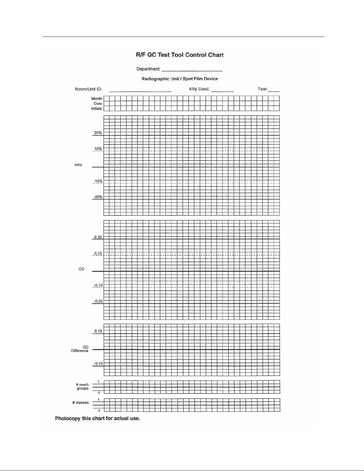
2.2 Analysis (See pages 2-3, 2-4 and 2-5)
As with the Mammography Accreditation Phantom, the results should be plotted on a graph rather than
just recorded in a table. The graph will make it much easier to detect any trends, such as a steady but
slow change in the fluoroscopic kVp or in the radiographic mAs. Such trends are an indication of
degradation in imaging system performance.
A well-tuned fluoroscopy system should be able to resolve at least the 20 mesh at the center of the image
in the 6" mode. From image to image, the smallest mesh visible should not decrease by more than one
step and the number of masses visible should not decrease by more than one. A change larger than this
should be investigated and corrected by a qualified service engineer. The fluoroscopic tube potential
should be between 70 and 90 kVp.
The mAs for radiographic systems, and the kVp and mA for fluoro systems should remain constant to
within 10%. No trends should be observed. A trend is defined as three or more points that move in the
same direction from the prior measurement. Even if a trend does not have any points that exceed the
control parameters, its cause should be investigated and corrected, as it is an indication of potential
system performance degradation. It is also possible to observe trends that do not move consecutively in
the same direction, but instead demonstrate either upward or downward motion over a longer period of
time. Such long-term trends, as when the points exceed control limits, should be monitored closely and
the cause investigated and corrected by a qualified service engineer. Data demonstrating the trend may
prove helpful to the service engineer, when investigating the cause.
2-2
Page 9
Operation
Analysis
2
2-3
Page 10

Nuclear Associates 07-647
Operators Manual
2-4
Page 11

Operation
Analysis
2
2-5
Page 12

Fluke Biomedical
Radiation Management Services
6045 Cochran Road
Cleveland, Ohio 44139
440.498.2564
120 Andrews Road
Hicksville, New York 11801
516.870.0100
www.flukebiomedical.com/rms
 Loading...