

Page 1

Nuclear Associates
Radiographic and Mammographic
Focal Spot Measurements Products
March 2005
Manual No. 38659 Rev. 2
©2004, 2005 Fluke Corporation, All rights reserved. Printed in U.S.A.
All product names are trademarks of their respective companies
Users Manual
Page 2

Fluke Biomedical
Radiation Management Services
6045 Cochran Road
Cleveland, Ohio 44139
440.498.2564
www.flukebiomedical.com/rms
Page 3

Table of Contents
Section 1: Introduction................................................................................................ 1-1
1.1 Introduction .................................................................................................. 1-1
Section 2: Operation.................................................................................................... 2-1
2.1 X-Ray Tube Focal Spot Measurements....................................................... 2-1
2.1.1 Purpose .................................................................................................. 2-1
2.1.2 Equipment Needed/Recommended for X-Ray Tube Focal Spot
Measurement............................................................................................... 2-1
2.1.3 Equipment Needed/Recommended for Mammographic X-Ray Tube
Focal Spot Measurements...................................................................... 2-2
2.1.4 Procedure for Over-Table X-Ray Tube Focal Spot Test Stand
Alignment..................................................................................................... 2-2
2.1.5 Procedure for Under-Table X-Ray Tube Focal Spot Test Stand
Alignment..................................................................................................... 2-4
2.1.6 Procedure for Slit Measurement or Mammographic X-Ray Tube Focal
Spot Measurement ................................................................................. 2-4
2.1.7 Procedure – Slit Measurement of Focal Spots ....................................... 2-7
2.1.8 Procedure – Pinhole Measurement Technique ...................................... 2-8
2.2 Star Measurement Technique...................................................................... 2-9
2.2.1 Physical Description of Star Test Pattern ............................................... 2-9
2.2.2 Instructions for Use................................................................................. 2-9
2.3 Procedure – Star Measurement Technique ............................................... 2-10
2.4 Procedure – Half-Value Layer Measurements ........................................... 2-12
i
Page 4

(Blank Page)
Page 5
Introduction
Introduction
1
Section 1
Introduction
1.1 Introduction
This manual is to be used for the following models:
07-624, 07-624-1000, 07-624-2222 - Slit Cameras
07-622 - Multipurpose Focal Spot/HVL Test Stand
07-623 - Mammography Focal Spot Measurement Test Stand
07-503, 07-509, 07-510, 07-542, 07-543, 07-550 - Star X-Ray Test Patterns for Measuring Focal Spot
Size
07-611, 07-613, 07-617 and 07-633 - X-Ray Pinhole Assemblies
Focal spot size and intensity distribution play a significant role in mammographic image quality. It is
particularly important to verify the size of the focal spot during acceptance testing of new mammographic
equipment or when a new x-ray tube is installed.
The National Electrical Manufacturers Association (NEMA) has developed a standard of describing a
technique for measuring the focal spot size. Some of the aspects of the standard are difficult, if not
impossible, to meet in the clinical setting. This manual follows as closely as possible, the present NEMA
standard.
Additional information regarding focal spot measurement techniques is available in the references cited
on page 2-12. Data is available that indicates that detail screen-film systems can be used in place of
direct x-ray exposure film, with a considerable reduction in x-ray tube loading
the slit measurement technique, the recommended NEMA technique, is a repeatable method for
acceptance testing, but that the star measurement technique can also be used as a repeatable method
for obtaining quality control measurements
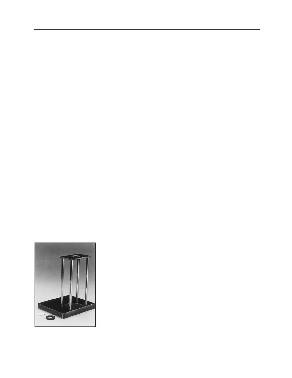
The American College of Radiology has published a document regarding quality control in
mammography. This document, which has separate sections for the radiologist, medical physicist, and
technologist, describes tests that will help assure quality mammographic imaging. The Mammography
Focal Spot Test Stand (Figure 1-1) can be used as one of the tools in the ACR Mammographic Quality
Control Program.
Figure 1-1. Mammography Focal Spot Test Stand (Model 07-623)
1
.
1
. Studies also indicate that
1-1
Page 6

(Blank page)
Page 7

Operation
X-Ray Tube Focal Spot Measurements
Section 2
Operation
2.1 X-Ray Tube Focal Spot Measurements
2.1.1 Purpose
To assure that the tube and x-ray tube focal spot size is within acceptable limits.
2.1.2 Equipment Needed/Recommended for X-Ray Tube Focal Spot
Measurements
1. Slit assembly, Pinhole, or Star Pattern.
2. A Focal Spot Test Stand (See Figure 2-1), with small and large adapter rings, and fluorescent
screen.
3. Focal Spot Test Stand Alignment Device (Figure 2-2).
4. 8" X 10" (20 x 25 cm) screen-film extremity or mammography cassette and film, or direct-exposure
x-ray film.
5. Clear plastic metric ruler.
6. Spirit level.
7. 6X magnifier with graticule scale in 0.1 mm divisions.
Figure 2-1. Multipurpose Focal Spot Test Stand (Model 07-622)
2
2-1
Page 8

Nuclear Associates Radiographic and Mammographic Focal Spot Measurement Products
*
x
-
x
-
Operators Manual
Figure 2-2. Focal Spot Test Stand Alignment Device Figure 2-3. Magnification Insert
2.1.3 Equipment Needed/Recommended for Mammographic X-Ray Tube Focal
Spot Measurements
1. Slit assembly, Pinhole, or Star Pattern.
2. A Focal Spot Test Stand (See Figure 1-1), with adapter ring, fluorescent screen and Magnification
insert (Figure 2-3).
3. Focal Spot Test Stand Alignment Device (Figure 2-2).
4. 18 x 24 cm mammography cassette and film and 8" x 10" direct exposure x-ray film.
5. Clear plastic metric ruler.
6. Spirit level.
7. 6X magnifier with graticule scale in 0.1 mm divisions.
2.1.4 Procedure for Over-Table X-Ray Tube Focal Spot Test Stand Alignment
1. Remove all objects between the focal spot and table, e.g., compression device, diaphragms, cones,
etc., which can be removed easily.
2. Place the focal spot test stand on the imaging table* (Figure 2-4).
3. Place the test stand alignment device in the top of the focal spot test stand (Figure 2-5).
4. Align the array of four beads so they are parallel with the anode-cathode axis of the x-ray tube.
5. Adjust the alignment device-to-film distance and focal spot-to-film distance (if variable) to obtain the
correct magnification factors (Table 2-1).
6. Level the base of the test stand with the spirit level, using the unit adjustments. Verify that the top of
the test stand is also level.
7. Place the fluorescent alignment screen on the test stand base plate.
8. Set a radiographic technique of about 28 kVp, 50 mA, and 2 sec for mammographic units. For R/F
units set the radiographic technique at 75 kVp, 50 mA and 2 sec.
9. Rough alignment* can be carried out using the collimator light with the room lights off.
10. Turn off all room lights and view, on the fluorescent screen, the x-ray image of the five beads*.
(This usually requires two people.)
11. Shift the test stand to assure that the stand is aligned with the central ray*, i.e., the one bead is
centered between the four beads (Figure 2-6).
12. Replace the test stand alignment device with the magnification insert.
13. Place the direct exposure x-ray film in the test stand tunnel.
Unlike conventional
i.e., near the chestwall side.
ray equipment, the central or perpendicular ray is usually located near the edge of the
ray field,
2-2
Page 9

Operation
X-Ray Tube Focal Spot Measurements
14. Select a technique of 28 kVp and 50 mAs for mammographic units. For R/F units use 75 kVp, 300
mA for direct exposure film and 30 mAs for cassette exposure.
15. Expose the film at the selected technique factor. Film density should be between 0.80 and 1.20
above the base-plus-fog level of the film.
Figure 2-4. Focal Spot Test Stand on Table Figure 2-5. Focal Spot Test Stand
Alignment Device
(Over-Table X-Ray Tube) on Top of Test Stand
Figure 2-6. Radiograph of the Five Beads in the Focal Spot Test Stand Alignment Device:
a. b.
a. Correctly aligned
b. Improperly aligned
2
Table 2-1.
Minimum Magnification for Slit, Pinhole,
or Star Measurement Technique
Nominal Focal
Spot Size (F, mm)
F < 0.4
0.4 < F < 2.5
F > 2.5
Magnification
> 3
> 2
> 1
2-3
Page 10

Nuclear Associates Radiographic and Mammographic Focal Spot Measurement Products
Operators Manual
2.1.5 Procedure for Under-Table X-Ray Tube Focal Spot Test Stand Alignment
1. Level the tabletop using a spirit level and place the test stand on x-ray tabletop (Figure 2-7). Assure
that the leveling screws are flush with the bottom of the stand.
2. Level the bottom of the stand using a spirit level, by adjusting the leveling screws.
3. Place the large adaptor ring and test stand alignment device on the base of the stand.
4. Rotate the test stand alignment device array of four beads so they are parallel to the anode-
cathode axis.
5. Repeat steps 4 and 7 from the Procedure for Over-Table X-Ray Tube Focal Spot Alignment,
Section 2.1.4.
6. Place the image intensifier tower over the stand and verify that the tower and x-ray tube are
aligned, i.e., the interlocks allow fluoro.
7. Center the image of the test stand alignment device, using the fluoroscopic image on the TV
monitor as a guide, by moving the stand. It may be necessary to adjust the mA and kVp manually to
provide a good image.
Figure 2-7. Focal Spot Test Stand on Table (Under-Table X-Ray Tube)
2.1.6 Procedure for Slit Measurement For Mammographic X-Ray Tube Focal Spot
Measurements
1. Replace the magnification insert with the slit assembly, parallel to the anode-cathode axis.
2. Place the mammographic cassette in the focal spot test stand tunnel.
3. Select a technique of about 28 kVp and 30 mAs for Kodak Min R Fast screens with TMM II film.
4. Align the slit assembly parallel to the anode-cathode axis to make the focal width measurement.
5. Expose the cassette at the selected technique factors. Film density should be between 0.8 and 1.2
above the base-plus-fog of the film.
6. Rotate the slit assembly 90° to measure the focal length.
7. Expose the cassette or film at the selected technique factor.
8. Process and view the slit images (Figure 2-8).
2-4
Page 11

Operation
X-Ray Tube Focal Spot Measurements
9. On the radiograph of the magnification insert, measure the distance (in centimeters) between the
images of the holes of the magnification insert using the ruler.
10. Divide image hole separation by 1 cm, the separation of the holes in the magnification insert.
Calculate the magnification using the following formula:
2
image hole separation
[
1 cm
For example, assume the image hole separation was measured as 3.20 cm
3.20 cm
[
1 cm
Figure 2-8. Slit Image Parallel and Perpendicular to the Anode-Cathode Axis
11. Measure across the middle of each slit image using the magnifier lens (with a built-in graticule). The
measurement across the band parallel to the anode-cathode axis is related to the width of the focal
spot. The measurement of the band perpendicular to the anode-cathode axis is related to the
"length of the focal spot.
12. To determine focal spot size, divide the measured width and length by the magnification factor. For
example, if the measured length of the slit image is 1.76 mm then:
]
- 1 = 2.20
]
- 1 = Magnification
1.76
[
]
2.20
13. Since many mammographic x-ray tubes are mounted at an angle (the anode-cathode axis is not
parallel to the image receptor), it is necessary to correct the focal spot length measurement for the
tube assembly tilt angle. The following formula is used:
L = F
where
L = the actual focal spot length
F = the users measured length
A = x-ray tube anode (target) angle (Provided by the x-ray tube manufacturer.)
= 0.80 mm (length of focal spot)
A)
]
Sin (A)
[
Sin (T +
2-5
Page 12

Nuclear Associates Radiographic and Mammographic Focal Spot Measurement Products
Operators Manual
T = tube assembly tilt angle (Provided by the x-ray system manufacturer.)
For example, for a 0.80 mm measured focal spot length (F), an anode angle (A) of 20°, and a tube
assembly tilt angle of 8°, one obtains
L = 0.80 mm
L = 0.80 mm
14. Compare the dimensions to the focal spot size tolerance limits in Table 2-2. The manufacturer may
not accept screen-film slit image measurements for acceptance testing purposes. In this case, it
may be necessary to repeat the procedure using direct exposure x-ray film.
Sin (20°)
[
Sin (8° +
0.34
[
0.47
20°)
]
]
= 0.58
mm
Table 2-2.
Focal Spot Size Tolerance Limits
(For Slit Camera Method)
Nominal Focal Spot
Designation (F)
0.05 0.075 0.075
0.1 0.15 0.15
0.15 0.23 0.23
0.2 0.30 0.30
0.25 0.40 0.40
0.3 0.45 0.65
0.4 0.60 0.85
0.5 0.75 1.1
0.6 0.90 1.3
0.7 1.1 1.5
0.8 1.2 1.6
0.9 1.3 1.8
1.0 1.4 2.0
1.1 1.5 2.2
1.2 1.7 2.4
1.3 1.8 2.6
1.4 1.9 2.8
1.5 2.0 3.0
1.6 2.1 3.1
1.7 2.2 3.2
1.8 2.3 3.3
1.9 2.4 3.5
2.0 2.6 3.7
Maximum Focal Spot
Dimensions in mm (F
Width Length
)
eff
2-6
Page 13

Operation
X-Ray Tube Focal Spot Measurements
2.1.7 Procedure - Slit Measurement of Focal Spots
1. Replace the test stand alignment device with the slit assembly, parallel to the anode-cathode axis.
2. Place a direct exposure x-ray film or cassette under the base for over-table x-ray tubes or on top of
the stand for under-table tubes.
3. Using the x-ray tube rating chart, select a technique of about 75 kVp and one-half the maximum
rated mA at 0.1 sec exposure for the appropriate focal spot size.
4. Select the exposure time to obtain about 300 mAs for the direct exposure film or 30 mAs for the
cassette at a 36-inch (90 cm) source-to-image distance (film density should be between 0.8 and 1.2
above the base-plus-fog of the film).
5. Align the slit assembly parallel to the anode-cathode axis to make the focal width measurement.
6. Expose the cassette or film at the selected technique factors (steps, 3 and 4, above).
7. Move the cassette a few inches (to prevent double exposure).
8. Rotate the slit assembly 90° to measure the focal length.
9. Expose the cassette or film at the selected technique factor.
10. Process and view the slit images (Figure 2-9).
11. Measure the center-to-center distance between the localization holes on the radiograph using the
ruler.
12. Divide image localization hole separation by the small adapter ring localization hole distance (40
mm). Calculate the magnification using the formula below:
2
image hole separation
[
40 mm
For example, assume the image hole separation was measured as 90 mm
90 mm
[
40 mm
Figure 2-9. Slit Image Parallel and Perpendicular to the Anode-Cathode Axis
13. Measure across the middle of each slit image using the magnifier lens (with a built-in graticule). The
measurement across the band parallel to the anode-cathode axis is related to the width of the focal
spot. The measurement of the band perpendicular to the anode-cathode axis is related to the length
of the focal spot.
14. To determine focal spot size, divide the measured width and length by the magnification factor. For
example, if the measured width of the slit image measured 1.8 mm then
]
- 1 = 1.25
]
- 1 = Magnification
1.25
]
= 1.44 mm (width of focal spot)
2-7
1.8 mm
[
Page 14

Nuclear Associates Radiographic and Mammographic Focal Spot Measurement Products
Operators Manual
15. Compare the measured dimensions to the Focal Spot Size Tolerance Limits in Table 2-2. The
manufacturer may not accept the screen-film slit image measurements for acceptance testing
purposes. In this case it may be necessary to repeat the procedure using direct exposure x-ray film.
2.1.8 Procedure - Pinhole Measurement Technique
1. Replace the test stand alignment device with the appropriate pinhole assembly. (The size of the
pinhole diameter is engraved on the pinhole assembly.)
The following pinhole assemblies should be used:
Nominal Focal Spot Size (F, in
mm)
0.3 < F <
1.2 < F <
2. Cover the localization holes only, not the pinhole insert, with 0.25 mm lead-equivalent rubber. (This
reduces the exposure and film density of the localization holes so that it will be easy to measure the
distance between them.)
3. Place a cassette under the base for over-table x-ray tubes or on top of the stand for under- table
tubes.
4. Expose the cassette. A suggested x-ray setting for the 0.075 mm pinhole assembly (for use with a
focal spot size between 1.0 mm and 2.5 mm) is 75 kVp and 100 mAs using Kodak Lanex Fine
screens and Kodak TML film.
5. Develop and examine the resulting image of the focal spot (Figure 2-10). If the density of the
densest portion is between 0.8 and 1.2, the exposure is satisfactory. If the density range is
unsatisfactory, adjust the exposure conditions and repeat.
6. Measure the center-to-center distance between localization holes on the radiograph using the ruler
and determine the magnification using the formula:
image hole separation
[
Sin (T + A)
where 13 mm is the separation of the localization holes in the pinhole assembly.
7. Place the focal spot image on an illuminated surface and measure with a 6X magnifier with graticle
scale. Most focal spots consist of two fairly dark lines having a relatively lighter area between them.
The focal spot dimensions are determined by measuring all perceptible portions of the image width
and length.
8. Follow step 14 of the Slit Measurement Procedure in Section 2.1.7.
9. For line-focus tubes, the measured focal spot length
0.7.
10. Suggested focal spot size tolerances are given in Table 2-3. However, these measurements may
not be accepted by the manufacturer for acceptance test purposes. In this case, the size should be
verified using the slit measurement technique.
1.2 07-613 0.030 mm
2.5 07-617 0.075 mm
F > 2.5 07-611 0.100 mm
]
- 1 = Magnification
Pinhole Diameter
Model
should be multiplied by a correction factor of
2-8
Page 15

Figure 2-10. Pinhole Image with Localization Holes
Table 2-3.
Suggested Focal Spot Size Tolerances
(For Pinhole Camera Method)
Nominal Focal
Spot Size (F, mm)
F < 0.8
0.8 < F < 1.5
F > 1.5
Tolerance (%)
Minus Plus
0 50
0 40
0 30
Operation
X-Ray Tube Focal Spot Measurements
2
2.2 Star Measurement Technique
2.2.1 Physical Description of Star Test Pattern
The Model 07-503, 07-503-1 and 07-503-2 consists of 60 spoke pairs divided into four 15° sectors. Each
spoke diverges at an angle of 0.5°.
The Model 07-509, 07-509-1 and 07-509-2 consists of 44 spoke pairs divided into four 45° sectors and
diverging at an angle of 2° for each spoke.
The Model 07-510, 07-510-1 and 07-510-2 is divided into 90 spoke pairs; each spoke diverges at an
angle of 2°.
The Model 07-542, 07-542-1 and 07-542-2 consists of 56 spoke pairs divided into four 28° sectors and
diverging at an angle of 1° per spoke.
The Model 07-543, 07-543-1 and 07-543-2 consists of 48 spoke pairs divided into four 35° sectors. Each
spoke diverges at an angle of 1.5°.
2.2.2 Instructions for Use
Focal spot size can be determined with the 07-503, 07-503-1, 07-503-2, 07-509, 07-509-1, 07 -509-2, 07510, 07-510-1, 07-510-2, 07-542, 07-542-1, 07-542-2, 07-543, 07-543-1 and 07-543-2 test patterns by
observing the regions of blurring which occur when the star pattern is radiographed. Radiation from
different areas of the focal spot will cause a periodic blurring of the pattern image. Knowledge of the
geometric factors and the distance from the center of the pattern to the region where blurring occurs will
permit the calculation of the focal spot size.
2-9
Page 16

Nuclear Associates Radiographic and Mammographic Focal Spot Measurement Products
Operators Manual
NOTE
The minimum focal spot size measurable with the
2° star is 0.5 mm. For smaller focal spots, a 1.5°
star (07-543), a 1° star (07-542) or a 0.5° star (07-
503) should be used.
2.3 Procedure - Star Measurement Technique
1. Replace the test stand alignment device with the appropriate star test pattern.
2. Place a direct exposure x-ray film under the base for over-table x-ray tubes or on top of the stand
for under-table tubes.
3. Select a technique of 75 kVp, one-half of the maximum mA and about 40 mAs.
4. Expose the x-ray film at the selected technique factors.
5. Process the film and examine the image (See Figure 2-10).
6. Determine the magnification (M) by dividing the diameter of the radiographic image of the star
pattern by the true diameter (45 mm) of the spokes only, i.e., do not include the outer edge of the
pattern (See Figure 2-10).
7. Scan image of the star pattern inward from the periphery to find the outer-most region at which the
image of the sectors bends or disappears. This is the region of zero contrast. Measure the diameter
of this region across its greatest extent. Repeat the measurement in the perpendicular direction. Let
these diameters be called D
8. The focal spot size corresponding to the individual diameter dimensions can be determined by
formula:
[
F =
Where: F is the focal spot size in mm.
N is the angle of the star pattern line (which is marked on the test pattern: 0.5°, 1°, 1.5°, or
2°).
D is the diameter of the zero contrast region in mm.
M is the magnification.
9. For the radiograph shown:
N = 2
] [
N D
57.3
x
and D2.
1
(M-1)
]
Magnification M =
(M-1) = 1.18
[
98 mm
45 mm
]
= 2.18
For the anode-cathode dimension:
D1 = 28 mm
2
[
57.3
F
= 0.83 mm
1
x
]
28
[
1.18
]
mm F1 =
2-10
Page 17

For the transverse dimension:
D2 = 34 mm
Operation
Procedure-Star MeasurementTechnique
2
2 34
[
F
=
2
The focal spot is 0.8 mm x 1.0 mm at the kVp and mA setting used.
10. Since these measurements yield the equivalent homogenous focal spot size they cannot be
compared directly to specified tolerances in Table 2-2, or Table 2-3. However, any changes
in the focal spot size with this technique should be indicative of changes in the actual size. In this
case, the size should be verified using the slit measurement technique.
Figure 2-11. Star Pattern Image Showing the Measurement of
]
x
57.3
the Diameter of the Image of the Pattern and the Diameter at Zero Contrast.
[
1.18
1.01
]
=
mm
noted
NOTE
1. Misalignment of the test stand with respect to
the central beam of the x-ray tube can alter the
measurements.
2. The focal spot size may change with mA and
kVp. Refer to methods for evaluating x-ray tube
1
blooming characteristics
.
3. The manufacturer may require the use of direct
x-ray exposed film instead of an extremity or
mammography cassette system for acceptance
testing.
4. With the Star Test Pattern, several regions of
zero contrast may be found on a single film. It is
extremely important that the largest one be
used. If there is any doubt (i.e., the focal spot
calculation yields low values), then a second
exposure with a lower magnification should be
made and evaluated.
2-11
Page 18

Nuclear Associates Radiographic and Mammographic Focal Spot Measurement Products
Operators Manual
5. For the Star Test Pattern, the formula and data
presented yield the equivalent homogeneous
focal spot size, not the actual size.
2.4 Procedure - Half-Value Layer Measurements
1. Place the focal spot test stand on the tabletop. Adjust the leveling screws so that the base is raised
1" (2.5 cm) above tabletop.
2. Place a sheet of lead under the base.
3. Adjust the stand so that the top is located at one-half of source-to-tabletop distance, e.g., for a 40"
source-to-table-top distance adjust the stand to 20".
4. Place both the large and small adaptors in the top of the stand.
5. Collimate the x-ray beam to the top aperture of stand.
6. Place the ionization chamber on the base just above the aperture (Figure 2-11).
7. Select the technique factors that will produce about 300 mR at 80 kVp.
8. Make an exposure without added aluminum and record the result.
9. Add 2 mm of type 1100 aluminum.
9. Make an exposure and record the result.
10. Repeat steps 9 and 10, adding an additional 1 mm of aluminum each time until the exposure
reading is approximately 100 mR.
12. For data analysis, potential problems, and acceptance limits, See Reference 2 on page 2-12.
2-12
Page 19

Figure 2-11.
Arrangement of the Focal Spot
Test Stand for Measurement of
the Half-Value Layer
References:
Operation
Procedure- Half-Value Layer Measurements
2
1. Everson J.D., Gray J.E., "Focal-Spot Measurement: Comparison of Slit, Pinhole and Star
Resolution Pattern Techniques," Radiology
, 1651 (1987), 261-264.
2. Measurement of Dimensions and Properties of Focal Spots of Diagnostic X-Ray Tubes, Standards
Publication No. XR 5-1984 National Electrical Manufacturers Association (NEMA), 2101 L Street
N.W., Washington, DC 20037.
3. J.E. Gray, N. T. Winkler, J.G. Stears, E.D. Frank, "Quality Control in Diagnostic Imaging," (Aspen
Systems Corporation, Rockville, Maryland).
4. American College of Radiology, "Mammography Quality Control-Manual for Radiologists,
Physicists, and Technologists," (1990), Reston, Virginia.
2-13
Page 20

Fluke Biomedical
Radiation Management Services
6045 Cochran Road
Cleveland, Ohio 44139
440.498.2564
www.flukebiomedical.com/rms
 Loading...