

Page 1

Victoreen 07-494
Wide-Range Digital kVp Meter
Operators Manual
December 2006
Manual No. 168001 Rev. 4
©2006 Fluke Corporation, All rights reserved. Printed in U.S.A.
All product names are trademarks of their respective companies
Page 2

Fluke Biomedical
Radiation Management Services
6045 Cochran Road
Cleveland, Ohio 44139
440.498.2564
www.flukebiomedical.com/rms
Page 3

Table of Contents
Section 1: General Information................................................................................... 1-1
1.1 Product Description ..................................................................................... 1-1
1.2 Specifications............................................................................................... 1-2
Section 2: Getting Started........................................................................................... 2-1
2.1 Receiving Inspection.................................................................................... 2-1
2.2 Storage........................................................................................................2-1
2.3 Routine Cleaning......................................................................................... 2-1
2.4 Indicators and Controls................................................................................ 2-2
Section 3: Theory and Applications........................................................................... 3-1
3.1 General........................................................................................................ 3-1
3.2 Filtration Effects........................................................................................... 3-1
3.3 Waveform Effects ........................................................................................ 3-2
3.4 Focus to Detector Distance (FDD)............................................................... 3-2
3.5 mAs Requirements...................................................................................... 3-2
3.6 Detector Positioning..................................................................................... 3-3
3.7 Low Battery.................................................................................................. 3-3
3.8 Applications ................................................................................................. 3-3
Section 4: Operation.................................................................................................... 4-1
4.1 Making a Measurement ............................................................................... 4-1
4.2 Interpreting Front Panel Warning Indications............................................... 4-2
4.3 Viewing the Waveform Output..................................................................... 4-3
Section 5: Calibration and Adjustments.................................................................... 5-1
5.1 Low Battery Threshold Adjustment.............................................................. 5-1
5.2 End of Shot Adjustment............................................................................... 5-3
5.3 50-90 kVp Calibration .................................................................................. 5-3
5.4 80-150 kVp Calibration ................................................................................ 5-3
Section 6: Maintenance and Troubleshooting........................................................... 6-1
6.1 Battery Replacement ................................................................................... 6-1
6.2 Accessing the Circuit Boards....................................................................... 6-1
6.3 Performance Verification (Calibration Constancy)....................................... 6-2
6.4 Verifying Supply Voltages............................................................................ 6-3
i
Page 4

(Blank page)
Page 5
General Information
Product Description
1
Section 1
General Information
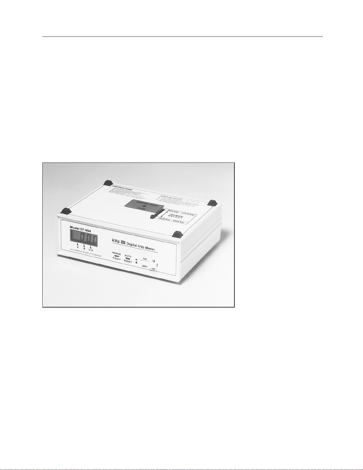
1.1 Product Description
The Model 07-494 Wide-Range Digital kVp Meter (Figure 1-1) is a portable, battery operated unit which
non-invasively measures the effective peak potential applied to a tungsten target diagnostic x-ray tube. It
uses two differentially filtered x-ray detectors whose ratio of integrated outputs is calibrated over the
ranges of 50 to 90 kVp and 80 to 150 kVp. The desired range is selected using the range selector on the
top of the unit.
Figure 1-1. Model 07-494 Wide-Range Digital kVp Meter
1-1
Page 6

Victoreen 07-494
Operators Manual
1.2 Specifications
Range
Resolution
Accuracy
mAs Requirements
Reproducibility
Filtration Effects
Calibration Frequency
Battery
Display
LED Indicators
Controls
Low: 50 kVp to 90 kVp
High: 80 kVp to 150 kVp
0.1 kVp
± 3% or 3 kV, whichever is greater (tungsten target x-ray tube
with 4.5 mm Al total filtration)
See Figure 1-2
± 1 kV or 1%, whichever is greater
50 kVp - 90 kVp range: less than 3.5% with 5.3 mm aluminum
added
80 kVp – 150 kVp range: less than 3% with 8 mm aluminum
added
One (1) year
Type: 9 V alkaline, NEDA 1604 (IEC 6F22) or alkaline equivalent
Life: 75 hr. typical
3 ½ digit, 0.5" high LCD with LO BAT indicator;
Below Range kVp: Flashing middle decimal point
Above Range kVp: Flashing left decimal point
Above Range mAs: Flashing right decimal point
Below Range mAs: Flashing right decimal point and 00.0
display
Auto Reset: New exposure detected, last kVp reading cleared
Range Fault: Range select sliding filter not properly engaged
Power Switch: ON/OFF
Phase Selection Switch: Single phase/3 phase
Filter Range Selection Switch: 50 to 90 kVp or 80 to 150 kVp
Connectors
Dimensions
(H x W x D)
Weight
Environmental Specifications Temperature:
1-2
BNC connector for waveform output
2.5 in. x 8 in. x 6 in.
(6.4 cm x 20.3 cm x 15.2 cm)
2.4 lbs. (1.1 kg)
Operating: 59 to 104° F (15 to 40° C)
Storage: - 0 to 122° F (-18 to +55° C)
Relative Humidity:
Operating: 0 to 90% non-condensing
Storage: 0 to 90% non-condensing
Page 7
Victoreen 07-494
Operators Manual
.
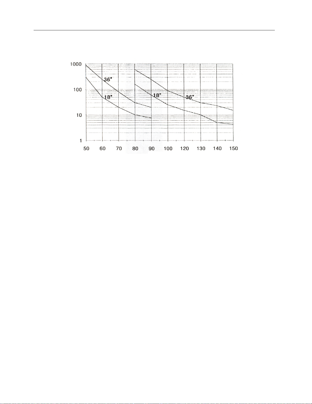
mA
Figure 1-2. mAs vs. kVp, Minimum Requirements (Typical Single Phase X-ray Unit)
kVp
1-2
Page 8

Victoreen 07-494
Operators Manual
(Blank page)
Page 9

Getting Started
Receiving Inspection
Section 2
Getting Started
2.1 Receiving Inspection
Upon receipt of the instrument:
1. Inspect the carton(s) and contents for damage. If damage is evident, file a claim with the carrier and
contact Fluke Biomedical, Radiation Management Services at 440.248.9300.
2. Remove the contents from the packing material.
3. Verify that all items listed on the packing list have been received and are in good condition. The
following items are shipped with the Model 07-494 kVp Meter
a. Part No.168005, Model 07-494 kVp III.
b. Part No.16-29, 9 V Alkaline Battery
c. Part No.168001 Instruction Manual
d. Part No. 010023 Registration Card
If any of the listed items are missing or damaged,
notify Fluke Biomedical at 440.248.9300.
2
2.2 Storage
If necessary to store the kVp meter prior to use, pack it in the original container if possible. Be sure the
storage area is free of corrosive materials, vibrations, and fluctuations in temperature and humidity. Also
be sure the environmental specifications (refer to Section 1-2, Specifications) are not exceeded.
2.3 Routine Cleaning
Do not immerse the Model 07-494 Wide-Range
Digital kVp Meter. This unit is not waterproof. Liquid
could damage the circuits. The unit should be kept
clean and free of dirt and contamination. The unit
may be cleaned by wiping with a damp cloth using
any commercially available cleaning or
decontaminating agent.
2-1
Page 10
Victoreen 07-494
Operators Manual
2.4 Indicators and Controls
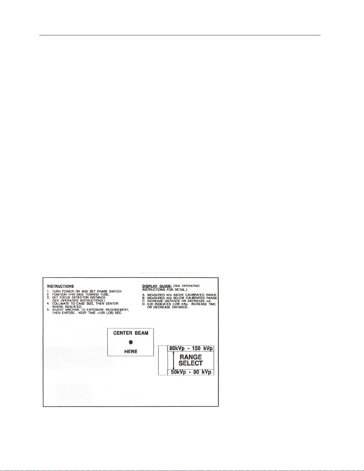
Top Panel
The top panel (Figure 2-1) includes brief operating instructions, beam center indication, display guide for
warning indicators A through D, and the range selector switch.
The range selector switch allows the operator to select the appropriate kVp range for the measurement.
When the range selector is set to 80 - 150 kVp, a second filter pair is positioned above the photodiodes
and a separate calibration is applied to the measurement circuit.
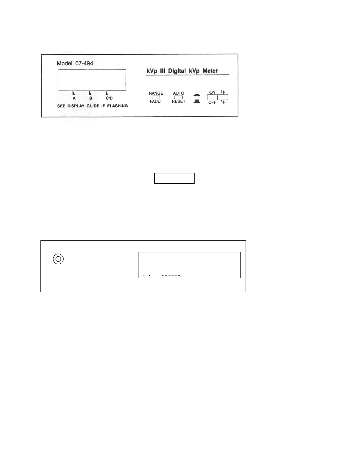
Front Panel
Refer to Figure 2-2 for front panel layout.
Numeric Readout: A 3-½ digit LCD display indicates the kVp value, provides warning status (flashing
decimal points), and indicates low battery voltage (LO BAT). Warning indications are listed on the top
panel and discussed further in Section 4, Operation.
Auto Reset LED: The auto reset LED is lit whenever the kVp Meter detects an x-radiation. The LED will
be on for 0.5 seconds or for the duration of the exposure, whichever is greater. The previous reading is
cleared when the LED turns on.
Range Fault LED: The range fault LED is lit whenever the range selector is between ranges or not
properly engaged.
Power Switch (ON/OFF): The power switch is an alternate action switch used to turn the instrument on or
off. The LCD readout is active when power is applied.
Phase Switch (1φ-3φ). The phase switch allows the operator to select either single phase (1φ) or three-
phase (3φ) operation. When the phase switch is in the 1φ position, the displayed value corresponds to a
single-phase waveform produced by a single-phase x-ray machine. When the phase switch is in the 3φ
position, the displayed value is the single phase calibrated output multiplied by a constant to compensate
for differences between 3 phase (or DC) and single phase waveforms.
Figure 2-1. Top Panel
2-2
Page 11
Getting Started
Indicators and Controls
Figure 2-2. Front Panel
Rear Panel
Refer to Figure 2-3 for rear panel layout.
Battery Access Cover: The battery access cover is located on the rear panel. Refer to Section 5,
Maintenance for battery replacement procedures.
Be sure the unit is turned OFF before removing the
batteries.
BNC Connector: A BNC connector, located on the rear panel, provides a signal from the radiation
detection diodes. The signal can be observed on an oscilloscope during an exposure. However, the
signal lasts only as long as the exposure. Therefore, a storage scope or camera is required to view the
signal for extended periods of time.
2
Figure 2-3. Rear Panel
Scope
CAUTION: Turn off power switch
before replacing battery. Use
MN16404 or equivalent alkaline
2-3
Page 12

Victoreen 07-494
Operators Manual
(Blank page)
Page 13

Theory and Applications
General
3
Section 3
Theory and Applications
3.1 General
The kVp measurement is computed from a measurement of the linear absorption coefficient (µ) of the
hardened x-ray beam. As the kV increases, µ increases, as discussed in the following paragraphs.
An x-ray beam is composed primarily of two parts - the bremsstrahlung radiation and the characteristic
radiation. Bremsstrahlung radiation predominates below 70 kV. When the beam potential crosses the 70
kV threshold, an apparent beam hardening takes place due to the sudden increase in the emission of
higher energy x-rays. The linear absorption coefficient, µ, increases at continually faster rates until
approximately 90 kV. Above 90 kV, the characteristic radiation becomes less important and contributes
less hardening to the beam. The bremsstrahlung radiation again dominates, and μ increases at a slower
rate. Use of dual range filters above 90 kVp helps minimize this effect.
3.2 Filtration Effects
A slight change in the beam spectrum being measured results in a change in the µ as described above.
This change may be caused by filtration differences with respect to the calibration beam. With lower
filtration, the x-ray beam is as hard as the calibration beam and the results are lower. With more filtration,
the beam is harder than the calibration beam and the results are higher. Refer to Table 3-1.
Table 3-1. Filtration Effects
Selected Range kVp
50 – 90 kVp
80 – 150 kVp
The results in Table 3-1 were reduced from data taken with a single-phase machine with 4 mm Al
inherent filtration. The values in the display increase column represents the % change in displayed kV for
each added mm Al filtration. The correlation coefficient (r) was above 0.99 for all curves. The filtration
varied from 0 to 8 mm Al.
To correct the display for tube filtration above 4 mm Al, reduce the display by F% where:
F = (%/mm Al) x (Tube Filtration - 4 mm Al).
Use the %/mm Al value closest to the kVp results.
65
80
100
120
Display Increase
(%/mm AI)
0.34
0.40
0.40
0.45
Tube filtration effects below 4 mm Al have not been studied. It is suggested for the best accuracy in kVp
measurements that the tube filtration be increased to 4 mm Al if it is less than that. To test the filtration
present on the tube, measure the HVL of the beam with 80 kVp set on the tube. For 80 kVp and 4 mm Al
filtration, the HVL should be 3.5 mm Al. An HVL less than 3.5 mm Al indicates that the filtration is less
than 4 mm Al.
3-1
Page 14

Victoreen 07-494
Operators Manual
3.3 Waveform Effects
Beam spectrum changes also occur with different waveforms. Single-phase waveforms display different
readings than three phase waveforms, depending on the position of the range selector switch. Correction
for waveform effect is made by selecting the appropriate position (i.e., single phase or three phase) using
the front panel phase selection switch.
3.4 Focus to Detector Distance (FDD)
The Focus to Detector Distance (FDD) affects the mAs requirements as discussed in Section 3.5, mAs
Requirements. Table 3-2 lists FDD settings generally used to keep the mAs requirement between 20 and
100. The FDD does not affect the accuracy of the kV results.
Table 3-2. FDD Settings
Selected Range kVp FDD
50 – 90 kVp
80 – 150 kVp
50 to 70
70 to 90
80 to 100
100 to 150
18 in. (45 cm)
36 in. (30 cm)
18 in. (45 cm)
36 in. (30 cm)
3.5 mAs Requirements
The curves in Figure 1-2 (see Section 1-2, Specifications) are provided as guidelines for selecting the
mAs required for a particular kVp measurement. Any mAs beyond the required amount is not used in the
measurement.
To determine the mAs required:
1. Locate the kVp to be measured on the horizontal axis.
2. Read the mAs from the selected FDD. It may be necessary to interpolate between distances using
the inverse square law.
As examples:
For kVp = 70 and FDD = 18 in.,
the mAs = 20.
For kVp = 100 and FDD = 30 in.,
the mAs = (30 in. /36 in.) (30 in. /36 in.) 90 = 62.5
The curves in Figure 1-2 (see Section 1.2, Specifications) are derived from single-phase measurements.
Three phase machines generally require 70% of the mAs determined from the curves.
Specific mAs requirements depend on the following factors:
• Detector sensitivity
• Tube filtration
• Radiation waveform
• FDD
• mAs errors in the x-ray machine
3-2
Page 15

Theory and Applications
Detector Positioning
3
3.6 Detector Positioning
The kVp Meter should be positioned in the center of the beam. The measurement area of the meter is 2
square inches, and is located on the top panel of the unit. Measurements made on other parts of the
beam will result in inaccurate readings due to the fact that the beam spectrum is different for different
parts of the beam. The heel effect is an example of such a beam spectrum change. As an illustration of
the effect of detector positioning, place the kVp meter in a selected part of the beam, make an exposure,
and observe the displayed measurement. Then move the detector to another part of the beam, make
another exposure, and observe the displayed measurement. Notice that the two measurements are
significantly different.
3.7 Low Battery
A low battery indication is displayed when the battery voltage drops below a factory-preset value. The
preset value is high enough that there is not an immediate noticeable effect on the measurement results.
However, prolonged use of the Instrument in the low battery condition will result in decreased accuracy.
3.8 Applications
kVp Accuracy Determinations
With the Digital kVp Meter, it is possible to enter a diagnostic x-ray room and, within one minute,
determine kVp accuracy for several stations of the x-ray machine. As a result, a significant cause of poor
image quality can be immediately diagnosed without affecting patient throughput.
Calculating Generator Loading Effects
In an x-ray generator, when the load (mA) changes, the kV may also change. Often, the generator
circuitry has been designed to compensate for this effect so that there is not a change in kV as different
mA stations are selected. To test for this effect:
1. Determine the kV to be investigated and the maximum mA to be tested.
2. Determine the minimum mAs requirements for the kV from Figure 1-2 (see Section 1.2,
Specifications).
3. Set the distance (FDD) such that the high-test mA and 50 ms (1/20 sec.) correspond to the
minimum mAs requirements.
4. Make an exposure.
If a low mAs indication appears on the kVp meter,
set the timer to the next station.
5. Record the value displayed on the kVp meter.
6. Set the mA to the next lower position.
7. Increase the exposure time so that the mAs remains greater than or equal to the value determined
in Step 3.
8. Make an exposure.
9. Record the value displayed on the kVp meter.
10. Compare the values recorded in Step 5 and Step 9 to determine how well the generator
compensates for mA changes.
3-3
Page 16

Theory and Applications
Applications
To eliminate time as a variable, decrease the FDD and mA while holding time constant. Utilizing the
inverse square law:
3
FDD
NEW
= FDD
X SQRT (mA
MAX
NEW
/mA
MAX
):
where:
FDD
FDD
= FDD to be used with new mA,
NEW
= FDD used with the maximum mA, and
MAX
SQRT = Square root.
kVp vs. Time Studies
During an x-ray exposure, the kVp may vary as a function of time. This can be illustrated by keeping the
mA constant and changing the FDD to vary the measurement time.
The kVp Meter accumulates data until certain internal values are reached, and then it displays the result.
The measurement time is independent of the generator time. For example, if the minimum mAs
requirement for a particular kV position is 50, the mA is set to 500, and the exposure time is set to 1
second, the kVp meter will accumulate data only during the first 100 ms interval (=50 mAs). (Refer to the
discussion in Section 3.5, mAs Requirements.) Nine tenths of the shot is wasted and the displayed result
does not indicate what occurs during the tail end of the exposure. A greater portion of the total exposure
can be included by increasing the mAs requirement by increasing FDD. There is no limit on maximum
exposure time.
To implement this application:
1. Select the kV, the mA, and the longest exposure time to be studied. The product of the mA and
time should correspond to the minimum mAs requirements determined from Figure 1-2 (refer to
Section 1.2, Specification).
2. Set the FDD to correspond to the longest exposure time.
3. Make an exposure and record the results.
4. Decrease the FDD, which, in effect, decreases the exposure time according to the inverse square
law.
ISF = inverse square factor = SORT (TMAX)
where,
T= kVp measurement for the kVp, mA and distance values.
5. Make an exposure and record the results.
For a value of 65 kVp at a maximum FDD of 36 inches, using the low range filter set the minimum
required mAs is 150 (from Figure 1-2).
If TMAX = 2 sec, tube current = (150 mAs/2 s) = 75 mA (Table 3-3). If TMAX = 0.5 sec, tube current =
(150 mAs/0.5 s) = 300 mA (Table 3-4).
Table 3-3. kVp vs. Time Study at 75 mA
mA T (sec) ISF X FDD
MAX
FDD (Inches) Measured kVp
75 2.000 36.0
75 1.000 0.707 25.5
75 0.500 0.500 18.0
75 0.250 0.354 12.7
75 0.1250 0.250 9.0
3-5
Page 17

Table 3-4. kVp vs. Time Study at 300 mA
Theory and Applications
Applications
3
mA T (sec) ISF X FDD
300 0.500 1.000 36.0
300 0.250 0.707 25.5
300 0.125 0.500 18.0
300 0.067 0.365 13.1
MAX
FDD (Inches) Measured kVp
mAs Reciprocity Corrections
A mAs reciprocity examination of an x-ray system involves variation of the mA or time or both
simultaneously. An ionization chamber (RAD-CHECK Plus, Model 06-526) is used to measure the output
of the machine and mR values are then calculated. The mR values should be proportional to the mAs
quantity. Normally the kV is held constant on the generator.
As discussed above, the kV may not be a constant function of mA and time if there is a malfunction in the
machine.
When mAs reciprocity is being tested, noted variations in the mR value may be due to kV fluctuations as
well as mA and timer nonlinearities. A simple correction for mAs reciprocity fluctuations due to kV
changes can be made if the kV fluctuations are known. If the percent change in kV is small, the mR
output will change as the square function of the kVp. That is, the percent change in mR output is double
the percent change in kV over a small percentage range (Table 3-5).
Table 3-5. mAs Reciprocity
Measured kVp mA Time mAs
80 100 0.1 s 10 160 16.0
82 300 0.1 s 30 525 17.5
In Table 3-5 there is a 9.4% increase in mR/mAs values. There is a 2.5% increase in kVp value which
would contribute to an approximate 5% increase in mR output. The 94% non-linearity in mAs reduces to
9.4% -5% = 4.4% which is acceptable.
mR mR/mAs
From this analysis, it is evident that the mA/kV compensation needs correction, whereas, without this
analysis, the mA or time looks suspect. If the changes in kV and mAs are in the opposite direction, the
mAs reciprocity results from the mR values may be very nearly linear and a simple reciprocity check
would indicate that the machine seems to be functioning properly. However, the use of the kVp Meter
would indicate the kV error and possibly an error in the mAs which was being cancelled out by the kV
error.
Waveform Diagnostics
If the mA is held strictly constant, and filtration does not change through the exposure, then variations in
the radiation waveform can be interpreted as variations in the kV waveform. It is difficult to reduce the kV
waveform from a single detector waveform even if the mA is held strictly constant. Relative judgments can
be made from the radiation waveform; however, absolute judgments should be avoided. For example,
the maximum observed point on a radiation waveform corresponds to the maximum kV point in the
waveform, but it may also be closely aligned to a maximum in the mA waveform.
The radiation waveform can exhibit symptoms of one or more type of malfunctions in an x-ray system as
listed in to Table 3-6.
Table 3-6. Waveform Diagnostics
3-5
Page 18

Theory and Applications
Problem Symptom
Preheat problems Waveform intensity continues to increase over
the first few cycles.
Arcing Waveform exhibits sharp rises and spikes with
a duration of 10 to 1000 microseconds.
Overshoot Problems Waveform exhibits overshoot on the first 2 or
3 pulses (3 phase machine).
Contactor Bounce Waveform peaks contain noise or smaller
peaks riding on major peaks.
Rectifier Imbalance Relative peak heights are different and
repeatable (i.e., one high and one low, or, in a
three phase machine, high-medium-low, highmedium-low, high-medium-low.)
Load Effects Waveform exhibits drooping during a long
exposure.
Applications
3
3-5
Page 19

Operation
Making a Measurement
Section 4
Operation
4.1 Making a Measurement
Use the following procedure to make a kVp measurement:
1. Turn the power switch to the ON position. The following should appear on the display:
00.0
If the low battery indication is displayed, or if the
display fails to respond, replace the battery. Refer
to Section 6, Maintenance for battery replacement
procedures.
2. Set the phase switch to the single-phase (1φ) or three-phase (3φ) position according to the type of
machine being measured.
If a fluoroscopic or constant potential is being
measured, set the switch to the three-phase (3φ)
position. (For an x-ray machine operated in the
fluoroscopic mode, the loading on the generator is
much lighter than normal and the radiation
spectrum more closely resembles that produced by
a three-phase, rather than single-phase,
generator.)
3. Set the range selector switch (located on the top panel) to the appropriate range for the kV to be
measured.
4. Set the desired Focus to Detector Distance (FDD), using the guidelines listed in Table 4-1.
4
Table 4-1. FDD Settings
Selected Range kVp FDD
50 – 90 kVp
80 – 150 kVp
5. Collimate the beam to the case size, using the light field.
6. Position the detector so that it is centered in the beam as indicated on the top panel.
7. Determine the mAs value using the guidelines discussed in mAs Requirements (refer to Section 3,
Theory and Applications).
8. Make an exposure and read the displayed kVp.
50 to 70
70 to 90
80 to 100
100 to 150
18 in. (45 cm)
36 in. (30 cm)
18 in. (45 cm)
36 in. (30 cm)
4-1
Page 20

Victoreen 07-494
Operators Manual
If a kVp value is not displayed, try doubling the
exposure time or decreasing the FDD by 30%.
9. Observe any displayed warnings, including flashing decimals or a low battery indication.
Warning indications are interpreted on the top
panel and in the following paragraphs.
The Digital kVp Meter has an auto reset feature. It senses when a new exposure takes place, resets the
display for a new reading and turns on the Auto Reset LED for 0.5 seconds or the duration of the
exposure, whichever is greater.
4.2 Interpreting Front Panel Warning Indications
Front panel warning indications are listed in Table 4-2.
A flashing decimal point above the A on the front panel indicates that the measured kVp is above the
calibrated range; that is, the kVp is above 150 kVp with the range selector in the 80 to 150 kVp setting or
above 90 kVp with the range selector in the 50 to 90 kVp setting.
A flashing decimal point above the B on the front panel indicates that the measured kVp is below the
calibrated range; that is, that the kVp is below 80 kVp with the range selector in the 80 to 150 kVp setting
or below 50 kVp with the range selector in the 50 to 90 kVp setting.
Indication
A
B
C/D
(Display ≠ 00.00)
C/D
Display = 00.0
A flashing decimal point above the C/D on the front panel with a displayed value other than 00.0 indicates
that beam intensity is too high and the measurement is completed with less than 50 ms of radiation
waveform. Increase the FDD or decrease the mA to produce more accurate results. This is particularly
important for single-phase x-ray machines because the radiation spectrum changes dramatically
throughout e duration of 4 pulses. If the measured waveform contains less than 6 pulses of single-phase
rectification, a partial pulse has a significant contribution to the value of the average of the pulses. It is
less important for 3 phase machines because the radiation spectrum remains relatively constant
throughout the exposure.
Explanation
Measured kVp > calibrated range.
Measured kVp < calibrated range.
Beam intensity too high; measurement time too
short.
Beam intensity too low; measurement time too long.
4-2
Page 21

Operation
Interpreting Front Panel Warning Indications
4
For displayed values greater than 95 kVp a flashing
decimal point above the C/D on the front panel may
be impossible to avoid for any combination of mA
or distances. The sensitivity of the kVp Meter above
95 kVp increases such that the mAs requirements
become very low at short distances. More filtration
can be added to the X-ray beam with the sacrifice
of accuracy. Filtration effects are discussed in more
detail in Section 3, Theory and Applications.
A flashing decimal point the C/D on the front panel with a displayed value equal to 00.0 indicates that the
minimum mAs requirements have not been met. Increase either the time or the mA setting or decrease
distance to obtain the required results.
4.3 Viewing the Waveform Output
The BNC connector on the rear panel provides a signal from the unfiltered radiation detection diodes in
the kVp Meter. During the x-ray exposure, a voltage is present at the BNC connector and available for
display on an oscilloscope. Examination of the waveform will require photographing it on a conventional
oscilloscope or using a storage oscilloscope.
4-3
Page 22

Victoreen 07-494
Operators Manual
(Blank page)
Page 23

Calibration and Adjustment
Low Battery Threshold Adjustment
Section 5
Calibration and Adjustment
This instrument has been factory calibrated. Recalibration should be performed by the factory or a
qualified calibration facility every 12 months. Other than calibration, there are six potentiometers which
may require adjustment. The procedures are outlined in this Section. Refer to Figure 5-1 for
potentiometer location
5.1 Low Battery Threshold Adjustment
Potentiometer R25 adjusts the threshold for indicating LO BAT on the LCD display. Use the following
procedure:
1. Open the battery compartment on the rear panel.
2. Remove and disconnect the battery.
3. Connect a voltmeter between battery plus (TP3).
4. Connect a voltmeter between battery plus (TP3) and analog ground (TP4).
5. Turn on the power supply and adjust it for 9 V.
6. Turn on the kVp Meter. The voltmeter should read between 2.4 V and 3.2 V.
7. Slowly decrease the power supply voltage until the voltage at the test point starts to drop (between
6.5 V and 7.5 V).
8. Slowly increase the power supply until the voltage across the test points just returns to the value it
had prior to dropping off.
9. Turn R25 until LO BAT disappears from the display.
10. Turn R25 slowly in the opposite direction just until LO BAT reappears on the display.
11. Connect the voltmeter between analog ground and the power supply negative terminal.
12. Increase the power supply voltage until the voltmeter reads 4.5 V, being careful not to exceed 9 V
from the power supply. LO BAT should turn off at this point.
13. Replace the battery and close the battery compartment.
5
5-1
Page 24

Victoreen 07-494
Adj
Operators Manual
80 - 150 kVp
Calibration
Adjustments
TP1
R
R
TP3
TP2
Below
Batter
TP8
50 – 90 kVp
Calibration
ustments
R
RTP1
R33 TP7
Figure 5-1. Adjustment and Test Point Locations
R60
Three Phase
Adjustments
(R19 and R60)
R19
TP5
TP9
Low Battery
Threshold
Adjustment
TP1
TP4
5-2
Page 25

Calibration and Adjustment
End of Shot Adjustment
5.2 End of Shot Adjustment
R33 provides adjustment of the radiation detection diode sensitivity. Use the following procedure:
1. Connect the positive lead of a DVM to TP3.
2. Connect the negative lead of the DVM to TP4.
3. Record the DVM reading.
4. Connect the positive lead of the DVM to TP8.
5. Adjust R33 to obtain a reading on the DVM equal to 50% of the reading recorded in Step 3 (at
TP3).
The reading obtained in Step 5, after adjustment of
R33 should be between 1.2 and 1.5 V.
5.3 50 - 90 kVp Calibration
The adjustments for the 50 - 90 kVp range are R4 and R5. An independent accurate means of
measuring the kVp of the x-ray machine is necessary for proper calibration. The kVp meter must be
calibrated at 50 kVp and 85 kVp (+1%) to be within specification. Use the following procedure:
5
1. Set the front panel phase switch for single-phase or three-phase depending on the type of x-ray
machine used for calibration.
2. Set the range selector switch to the 50 - 90 kVp range.
3. Remove the cover from the meter.
4. Locate the meter at an FDD of 24 inches.
5. Set the x-ray machine to 50 kVp, 300 mA, and 1.5 seconds.
6. Make an exposure.
7. Adjust R5 until the display reads 50 kVp.
8. Set the x-ray machine to 85 kVp, 300 mA, and 0.3 seconds.
9. Make an exposure.
10. Adjust R4 until the display reads 85 kVp.
11. Repeat Steps 5 through 10 until the readings are accurate.
5.4 80 - 150 kVp Calibration
The two adjustments for the 80 kVp to 150 kVp range are R3 and R6. In this range the kVp meter must
be calibrated at 85 kVp and 140 kVp (±1%) to be within specification. Use the following procedure:
1. Set the front panel phase switch for single-phase or three-phase depending on the type of x-ray
machine used for calibration.
2. Set the range selector switch to the 80 - 150 kVp range.
3. Remove the cover from the meter.
4. Locate the meter at an FDD of 24 inches.
5. Set the x-ray machine to 85 kVp, 50 - 100 mA, and 0.3 seconds.
6. Make an exposure.
5-3
Page 26

Victoreen 07-494
Operators Manual
7. Adjust R6 until the display reads 85 kVp.
8. Set the x-ray machine to 140 kVp, 50 mA, and 0.3 seconds.
9. Make an exposure.
If the C/D decimal point is flashing, indicating that
the intensity of the exposure is too high, decrease
the mA or increase the FDD and repeat the
exposure.
10. Adjust R3 until the display reads 140 kVp.
11. Repeat Steps 5 through 10 until the readings are accurate.
5-4
Page 27

Maintenance and Troubleshooting
Battery Replacement
6
Section 6
Maintenance and Troubleshooting
6.1 Battery Replacement
When the internal battery no longer provides sufficient voltage for proper operation, a LOW BAT indicator
will appear in the upper left corner of the display. When this indication appears replace the battery as
follows:
1. Turn the power OFF.
2. Open the battery compartment on the rear panel.
3. Remove and disconnect the old battery.
4. Insert and connect a fresh 9 V NEDA type 1604 (or equivalent) battery.
5. Snap the battery compartment door closed.
6.2 Accessing the Circuit Boards
Use the following procedure to gain access to the circuit board components and test points:
Refer to Figure 5-1 (see Section 5, Calibration and
Adjustments) for adjustment and test point
locations.
1. Remove the two screws from the case bottom.
2. Carefully lift the top cover to expose the circuit board.
3. If necessary, remove the four screws which attach the slide filter to the circuit board to gain access
to the circuitry below the slider.
3. If required, remove the circuit board by removing the 4 nuts which hold it in the lower case.
To reassemble the unit:
1. Position the circuit board so that the mounting holes align with the screws in the lower case.
2. Position the standoff on the diode lead shield and attach the slide filter plate.
3. Carefully fit the top and bottom covers together.
4. Replace the two cover screws
6-1
Page 28

Victoreen 07-494
Operators Manual
6.3 Performance Verification (Calibration Constancy)
In this section, two methods are described for verifying the accuracy of the kVp meter. Both methods
require a careful collection of installation data and periodic re-measurement of that data. The voltage
divider method is more direct than the multiple x-ray machine method. However, if at least five x-ray
machines are used in the multiple machine test, the results are very positive.
Voltage Divider Method
If available, an x-ray voltage divider should be used concurrently during the initial testing of the kVp
Meter.
1. Choose two x-ray machines suited for the test. It is recommended that different types of machines
be used (e.g., use one three phase machine and one single phase machine).
2. Make comparative measurements of the voltage divider and the kVp Meter.
3. If an oscilloscope is used to measure the voltage divider, use an independent voltmeter to measure
the scope sensitivity each time.
Data with a kVp test cassette may be useful. Be
sure to note positioning error and film usage when
using the cassette.
4. Record all parameters of the measurement, including geometry, cable connections, tube ID,
generator ID, divider and kVp Meter waveform oscilloscope pictures, oscilloscope and voltmeter ID.
5. Periodically (every 6 months) or when a serious discrepancy occurs, repeat Steps 1 through 4 to
determine which piece of equipment is in error.
If two dissimilar x-ray machines are used, the
possibility of a systematic error is reduced. The kVp
Meter, divider, cassette results, and x-ray settings
should also be examined for constancy.
Multiple X-Ray Machine Method
If a voltage divider is not available, the following method may be used:
1. Choose several (if possible, at least five) x-ray machines suited for the test.
2. Make comparative measurements with each machine.
Data with a kVp test cassette may be useful. Be
sure to note positioning error and film usage when
using the cassette.
3. Record all parameters of the measurement, including geometry, cable connections, tube ID,
generator ID, and kVp Meter waveform oscilloscope pictures, oscilloscope, and voltmeter ID.
6-2
Page 29

Maintenance and Troubleshooting
Performance Verification (Calibration Constancy)
4. Periodically (every 6 months) or when a serious discrepancy occurs, repeat Steps I through 3 to
determine which piece of equipment is in error.
If the kVp meter suddenly produces different results
from previous tests on only one machine, then
there is a strong probability that the kVp Meter is
operating correctly. If all of the x-ray measurements
suddenly change, then the kVp Meter may not be
operating correctly.
6.4 Verifying Supply Voltages
Troubleshooting the kVp meter consists of verifying the supply voltages.
Equipment recommended for troubleshooting the kVp Meter includes:
1. A digital voltmeter (Fluke Model 77 or equivalent).
2. A storage oscilloscope (Tektronix Model 2430 or equivalent).
Use the following procedure:
6
1. Connect the DVM negative lead to TP4 (circuit ground).
All measurements will be made with reference to
TP4.
2. Apply power to the unit under test.
3. Test for the voltages listed in Table 7-1.
3. If any of the voltages cannot be verified, replace the faulty component (refer to the comments
column of Table 7-1).
The waveforms in Figures 6-2, 6-3, and 6-4 are provided for reference.
Table 6-1. Test Point Voltages
Test Point Voltage Comments
TP3 2.4 to 3.2 V Derived from U101 on VRM board.
TP5 -5.0 to 6.0 V Derived from U101 on VRM board.
TP10 1.2 to 1.6 V Derived from voltage divider R22, R23
6-3
Page 30

Victoreen 07-494
Operators Manual
CH1 = TP1
CH2 = TP8
Setup: Single phase x-ray machine
74.5 kVp @ 300 mA
28 “ SDD
CH1 1V
CH2 1V
CH1gnd
CH2gnd
Figure 6-2. Oscilloscope Waveform A
A 20ms -328mV CH1
CH1
CH2
6-4
Page 31

CH1 = TP1
CH2 = TP9
Setup: Single phase x-ray machine
74.2 kVp @ 300 mA
28 “ SDD
CH1 1V A 20ms 563mV CH1
CH2 1V
CH1gnd
CH2gnd
Figure 6-3. Oscilloscope Waveform B
Maintenance and Troubleshooting
Verifying Supply Voltages
CH1
CH2
6
6-5
Page 32

Victoreen 07-494
Operators Manual
CH1 = TP1
CH2 = TP2
Setup: Single phase x-ray machine
75.5 kVp @ 300 mA
28 “ SDD
CH1 1V A 20ms 563mV CH2
CH2 1V
CH1gnd
CH2gnd
Figure 6-4. Oscilloscope Waveform C
CH1
CH2
6-6
Page 33

(Blank Page)
Page 34

Fluke Biomedical
Radiation Management Services
6045 Cochran Road
Cleveland, Ohio 44139
440.498.2564
www.flukebiomedical.com/rms
 Loading...