

Page 1

Nuclear Associates 07-443
Clamshell Densitometer
February 2005
Manual No. 166001 Rev. 5
©2004, 2005 Fluke Corporation, All rights reserved. Printed in U.S.A.
All product names are trademarks of their respective companies
Users Manual
Page 2

Fluke Biomedical
Radiation Management Services
6045 Cochran Road
Cleveland, Ohio 44139
440.498.2564
www.flukebiomedical.com/rms
Page 3

Table Of Contents
Section 1: General Information................................................................................... 1-1
1.1 Product Description ..................................................................................... 1-1
1.2 Specifications............................................................................................... 1-2
Section 2
2.1 Zeroing the Unit ........................................................................................... 2-1
2.2 Making a Measurement ............................................................................... 2-1
2.3 Receiving Inspection.................................................................................... 2-2
2.4 Storage ........................................................................................................ 2-2
2.5 Battery Installation/Replacement ................................................................. 2-2
2.6 Display ......................................................................................................... 2-3
2.7 Controls ....................................................................................................... 2-3
2.8 Routing Cleaning ......................................................................................... 2-4
Section 3: Maintenance/Calibration ........................................................................... 3-1
3.1 Calibration Check ........................................................................................ 3-1
3.2 Step Table Accuracy.................................................................................... 3-1
3.3 Maintenance ................................................................................................ 3-2
3.4 Recommended Spare Parts......................................................................... 3-3
: Operation.................................................................................................... 2-1
i
Page 4

Page 5
General Information
Product Description
1
Section 1
General Information
1.1 Product Description
The Model 07-443 Densitometer is designed to measure transmission density per ANSI specification
PH2.19-1986. The unit’s high accuracy and reliability allow precise and repeatable measurement to be
made quickly and easily with very little operator training. In addition, due to its solid-state design and
rugged construction, the Model 07-443 requires a minimum amount of maintenance. By using the 07-443
Densitometer, readings of optical density for film media can be obtained directly, accurately, and
reproducibly.
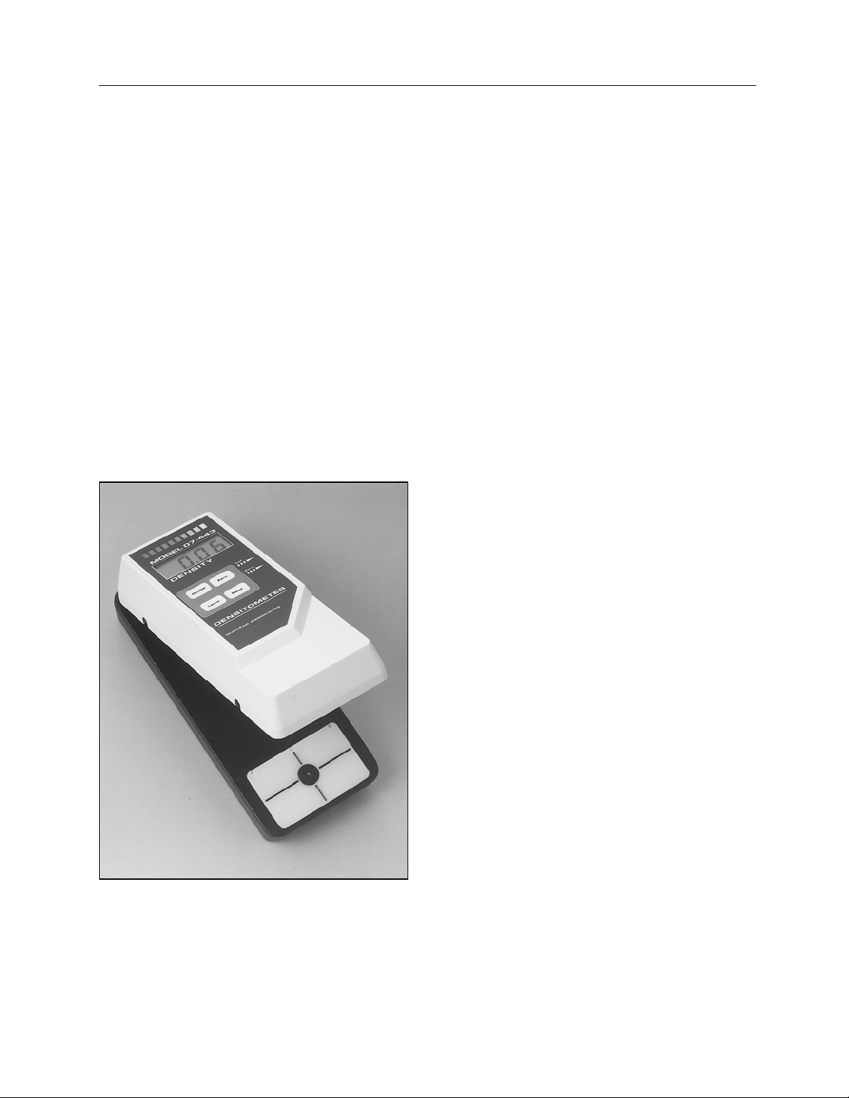
The 07-443 Densitometer features a rugged aluminum bottom casting, which houses four (4) AA batteries
and the detector light source. The top section of the Densitometer holds the 3 1/2 digit display, ON/OFF
push-button, and the READ, LAMP, and ZERO push-buttons. Refer to Figure 1-1 for a general view.
A 1 mm aperture is included as an accessory with the instrument. When changing apertures, the
instrument must be readjusted to zero by using the zero adjustment potentiometer located on the side of
the instrument.
Figure 1-1. Model 07-443 Densitometer
1-1
Page 6

Nuclear Associates 07-443
Operators Manual
1.2 Specifications
Density Range: 0 - 4.00 Density
Accuracy: +
Reproducibility: +
Operating Conditions: 50° F to 104° F (10° C to 40° C)
Maximum 90% Relative Humidity (non-condensing)
Aperture: 2 mm (1 mm Accessory)
Measuring Length: 5.3 inches (135 mm)
Display: 3 Digit 1/2 inch LCD, w/Polarity and Low Battery Indicator
Zero Range: Auto zeroes up to density 1.00 D
Sensor: 20 R/sec High Efficiency Silicon Photodiode
Controls: Zero: Push-button; automatically zeroes unit
Power: ON/OFF push-button turns unit power on/off
Calibration Control: Screwdriver adjustment; 20 turn potentiometer used to calibrate against a know
READ Push-button: Initiates read sequence
LAMP Push-button: Turns light source on for three (3) seconds
Light Source: Ultra bright lamp turns on during measurement; provides extremely long life with
Dimensions (H x W x D): 2.40 x 3.20 x 7.10 in. (61 x 81 x 180 mm)
Weight: 1.72 lbs. (78 g)
Power: Four (4) 1.5 V AA Batteries
Supplied Accessory: Part No. 010128, 5 step precision wedge Part No. 166055, 1 mm Aperture
Certification: Designed to measure diffuse transmission density per ANSI specification PH 2-
19-1986
0.02 D over specified range
0.01 D
step tablet.
minimal spectral and intensity degradation; reduces specimen heating to a
minimum.
1-2
Page 7

Operation
Zeroing the Unit
Section 2
Operation
2.1 Zeroing the Unit
Each time the Model 07-443 Densitometer is turned ON, and before a measurement is made, it must be
zeroed to ensure accurate measurements. Use the following procedure:
1. Press the ON/OFF push-button to turn the unit on.
2. Gently close the top section of the Densitometer until the Photo Head touches the aperture.
3. Holding the unit in the closed position, press the ZERO button once and wait until the display reads
0.00.
4. Slowly allow the top section of the unit to return to the open position.
5. Should the unit complete the Auto-Zero sequence and show a value either slightly higher or lower
than 0.00, it may be necessary to manually adjust the display to obtain a reading of 0.00. The Zero
Adjustment Pot, located along the right edge of the unit, is used for this purpose.
The zeroing procedure also allows the BASE/FOG value to be subtracted from all subsequent
measurements as follows:
1. Press the ON/OFF push-button to turn the unit on.
2. Place the BASE/FOG area over the aperture.
3. Gently close the top section of the unit until the photo head and the aperture are pressed tightly
against the film.
4. Holding the unit in the closed position, press the ZERO button and wait until the display reads 0.00.
5. Slowly open the unit.
The zero reference is now set to the BASE/FOG value. Subsequent measurements will be made
with respect to the BASE/FOG value.
2
2.2 Making a Measurement
1. Push the ON/OFF button to turn the unit on.
2. Zero the instrument (refer to Zeroing the Unit, step 2 through 4).
3. With a piece of film media or step wedge in hand, press the LAMP button. The lamp in the bottom
casting will turn on and stay on for about three (3) seconds.
4. Place the film media or step wedge on the light table and position the area to be measured over the
aperture (refer to Figure 2-1).
Press the LAMP Button as necessary to keep the
lamp illuminated.
NOTE
2-1
Page 8

Nuclear Associates 07-443
Operators Manual
5. When the film is in position, gently close the top section of the unit until the photo head and
aperture are pressed tight against the film.
6. Press the READ button. The measured density will be displayed.
7. Slowly allow the top section of the unit to return to the open position.
8 Remove the film media or step wedge.
9. Repeat steps 3 through 8 as required to make additional measurements.
Figure 2-1. Aperture Location
2.3 Receiving Inspection
Upon receipt of the unit:
1. Check the shipping carton (s) and their contents for in-shipment damage. If damage is evident, file
a claim with the carrier and contact Fluke Biomedical at 440.498.2564, or by Fax at 440.542.3682
immediately.
2. Check that all items listed on the packing slip are present and in good condition. If any items are
missing or damaged, contact Fluke Biomedical at 440.498.2564, or by Fax at 440.542.3682.
2.4 Storage
If the unit is to be stored prior to use, pack it in the original container (s) if possible, and store in an
environment free of corrosive materials, fluctuations in temperature and humidity, and vibration and
shock.
2.5 Battery Installation/Replacement
Use the following procedure to install/replace batteries.
NOTE
2-2
Page 9

A LOW BAT indicator will be displayed when the
batteries need to be replaced. This indicator may
flash briefly when a READ sequence is initiated;
however, the batteries need replaced only if the
indicator remains on for several seconds.
1. Remove the four (4) screws securing the battery cover on the bottom of the aluminum casting of the
densitometer.
2. If applicable, remove the used batteries.
3. Insert four (4) fresh AA alkaline batteries, being careful to observe proper polarity.
4. Replace and secure the cover, using the four (4) screws removed in step 1.
NOTE
When battery installation/replacement is complete,
be sure all hardware is back to its original place,
and all screws are tight.
2.6 Display
Density measurements are displayed on a 3 digit 1/2 in. LCD, featuring polarity and low battery
indications.
2.7 Controls
The Densitometer controls include an ON/OFF push-button (turns unit on/ off), a ZERO push-button
(automatically zeroes the unit), a LAMP Push-button (turns light source on for three (3) seconds), a READ
Push-button (initiates read sequence), Calibration Control, and Zero Adjustment. The Calibration Control
is a screwdriver adjustment for a 20-turn potentiometer that is used to calibrate against a known step
table. The Zero Adjustment pot is used to manually set the Auto-Zero for a reading of 0.00. Refer to
Figure 1-1.
2.8 Routine Cleaning
Do not immerse the Model 07-443. The unit is not
waterproof. Liquid could damage the circuits. The
unit should be kept clean and free from dirt and
contamination. The unit may be cleaned by wiping
with a damp cloth using any commercially available
cleaning or decontaminating agent.
Keep the underside of the photohead clean using
alcohol and a soft cloth as required. DO NOT USE,
under any circumstances, any other solvent.
CAUTION
2-3
Page 10

Page 11

Maintenance/ Calibration
Calibration Check
3
Section 3
Maintenance/ Calibration
3.1 Calibration Check
It is a good practice to perform a calibration check on the Densitometer at least once every two (2) weeks,
(more or less depending on the frequency of use of the unit). Use the following procedure:
1. Zero the instrument (refer to Section 3 -Operation).
2. Place step # 4 of the supplied precision step wedge over the aperture.
3. With the wedge in position, gently close the top section of the unit until the Photo Head and the
Aperture are pressed lightly against the wedge.
4. Press the READ button. The measured density will be displayed.
5. Slowly allow the top section of the unit to return to the open position.
6. Remove the step wedge.
7. Compare the density displayed in step 4 to the stated density on the step wedge.
8. Using a screwdriver, adjust the potentiometer (accessible from the right hand side of the top section
of the unit) until the reading displayed matches the stated density.
9. Press the READ button and wait for a reading. Repeat for each change in the calibration
potentiometer.
3.2 Step Table Accuracy
For quality control purposes, the calibration of the instrument with the supplied step tablet is sufficient.
However, it should be noted that the slope of the indicated density curve will change if any color shifts are
caused by the materials being measured. Although the light source is close to the ANSI standard of
typical response of the human eye, it is not exact. Therefore, films that produce a spectral shift may
produce consistently higher or lower density readings. In such cases, a calibrated step wedge of the
same material as being measured is necessary to adjust instrument calibration.
3-1
Page 12

Nuclear Associates 07-443
Operators Manual
3.3 Maintenance
This instrument contains CMOS integrated circuits.
Static charge normally present in a dry environment
or leakage current in soldering irons, or other nongrounded tools can instantly destroy CMOS
components. Do not attempt to remove or replace
ICs in this device without observing anti-static and
leakage current precautions. Service should be
performed only by a technician thoroughly familiar
with CMOS devices.
As with any precision measurement instrument, certain precautions and periodic maintenance procedures
are necessary:
1. Keep the underside of the photohead clean, using alcohol and a soft cloth as required. Do not use,
under any circumstances, any other solvent.
2. Periodically check the alignment of the aperture and the photo head. Misalignment may be due to:
a. Dropping the instrument.
b. Using excessive pressure to hold the instrument closed.
c. Letting the top section “slam” in the open position.
LAMP REPLACEMENT
WARNING
Use the following procedure to replace the lamp:
1. Remove the four (4) screws securing the cover on the bottom of the aluminum casting of the
densitometer.
2. Remove the cover to gain access to the pc board underneath.
3. Remove the two (2) screws holding the printed circuit board to the casting.
4. Remove the printed circuit board to gain access to the lamp.
5. Unsolder the used lamp.
6. Insert and solder the new lamp in place.
CAUTION
Too much heat from a solder iron can damage the
lamp. A 15-watt iron is recommended.
7. Replace and secure the printed circuit board to the casting using the two (2) screws removed in
step 3.
8. Replace and secure the cover, using the four (4) screws removed in step 1.
When lamp replacement is complete, be sure all
hardware is back to its original place on the
instrument. Also, be sure all screws are tight and
all washers are properly positioned.
NOTE
3-2
Page 13

Maintenance/ Calibration
Maintenance
If the photo head and the aperture are out of
alignment, contact Fluke Biomedical at
440.498.2654 or by Fax 440.542.3682.
NOTE
3.4 Recommended Spare Parts
Recommended spare parts are shown below:
Description
AA Alkaline Battery 750003 4
5 Step Calibration Tablet 010128 1
5 Step Calibration Tablet Label 010093 1
Lamp 680041 2
1 mm Aperture 166055 2
2 mm Aperture 166060 2
Part Number
Quantity
3
3-3
Page 14

Fluke Biomedical
Radiation Management Services
6045 Cochran Road
Cleveland, Ohio 44139
440.498.2564
www.flukebiomedical.com/rms
 Loading...