

Page 1

Nuclear Associates 07-440
Digital Densitometer II with RS-232C Interface
March 2005
Manual No. 163001 Rev. 3
©2003, 2005 Fluke Corporation, All rights reserved. Printed in U.S.A.
All product names are trademarks of their respective companies
Operators Manual
Page 2

Fluke Biomedical
Radiation Management Services
6045 Cochran Road
Cleveland, Ohio 44139
440.498.2564
www.flukebiomedical.com/rms
Page 3

Table of Contents
Section 1: General Information................................................................................... 1-1
1.1 Introduction .................................................................................................. 1-1
1.2 Specifications............................................................................................... 1-2
Section 2
2.1 General ........................................................................................................ 2-1
2.2 Receiving Inspection.................................................................................... 2-2
2.3 Setup ........................................................................................................... 2-2
Section 3: Maintenance and Calibration .................................................................... 3-1
3.1 Periodic Maintenance .................................................................................. 3-1
3.2 Aperture Alignment ...................................................................................... 3-2
3.3 Calibration.................................................................................................... 3-2
3.4 Lamp Replacement...................................................................................... 3-3
3.4.1 Table Lamps ............................................................................................ 3-3
3.4.2 Measurement Light Source...................................................................... 3-4
3.5 Recommended Spare Parts......................................................................... 3-5
: Operation.................................................................................................... 2-1
i
Page 4

(Blank page)
Page 5
General Information
Introduction
1
Section 1
General Information
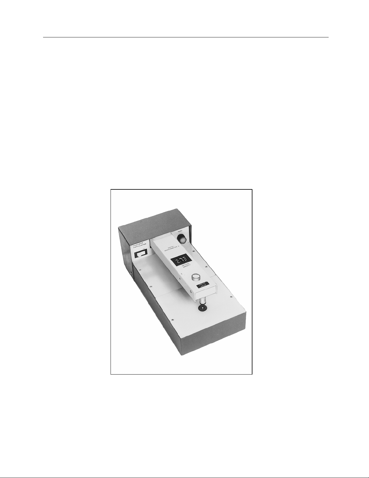
1.1 Introduction
The Model 07-440 Digital Densitometer is designed to measure optical density with high accuracy and
reliability. With minimum training, an operator can make the precise, repeatable measurements necessary
for accurate photographic film exposure and processing control. At the push of a button, the result of each
measurement is transmitted via an RS-232 interface which allows the operator to acquire this data on a
computer system.
Solid state dependability together with rugged construction make the instrument exceptionally stable over
long periods. Due to the dependability and construction of the instrument, maintenance requirements are
minimal.
Figure 1-1. Digital Densitometer II, Model 07-440
1-1
Page 6

Nuclear Associates 07-440
Operators Manual
1-2. Specifications
Table 1-1. Instrument Specifications
Feature
Density Range 0-4.50
Response Time
Warm-Up Time
Accuracy
Density Subtraction Zero control permits density subtraction of up to 4.50 with 3 mm aperture. Minus sign
Zero Control 10 turn control permits exact zeroing with flashing minus sign indicating correct zero
Zero Drift
Spectral Response
Supplied Apertures
Throat
Illuminated Table Area
Detector
Detector Light Source White LED provides extremely long life with minimum spectral and intensity
Readout Located on measurement arm; three L.E.D. digits with minus sign, 10 mm (0.4 in.)
Dimensions
(H x W x D)
Weight
Shipping Weight
Power Switch Selectable
Operating Conditions 10° C to 40° C (50° F to 104° F)
RS-232C Interface
Supplied Accessories Part No. 010128 Step Tablet for calibration
Specifications
<
2 seconds at optical density of 3.00
10 seconds maximum
± 0.02 at density of 3.00 with 1 mm aperture
included on display to show negative relative densities.
to within 0.002.
Negligible
Centered at approximately 465 nanometers
3 mm, 2 mm, and 1 mm diameter Aluminum
210 mm (8.25 in.)
120 x 140 mm (4.75 x 5.5 in.)
Silicon diode
degradation. Also reduce specimen heating to a minimum.
high.
4.9 in. x 6.3 in. x 13.4 in.
(125 mm x 160 mm x 340 mm)
7.5 lbs. (3.4 kg)
10 lbs. (4.3 kg)
115 VAC, 50/60 HZ, 15 W
230 VAC Unit available
Order #07-440-20
Fuses
For 115 VAC - Use 1.0 A, 250 V, AGC Fast Acting
For 230 VAC - Use 0.5 A, 250 V, AGC Fast Acting
Maximum 90% relative humidity, non-condensing
User selectable baud rates ASCII format
Four #37 lamps
One extra O-ring light seal
One set of three apertures
1-2
Page 7

Operation
General
Section 2
Operation
2.1 General
1. Select and position the proper aperture (small flat side UP) as outlined in Section 2-3, Set-Up.
2. Set the ZERO control as outlined in Section 2.3, Setup.
3. Place the film over the aperture with the emulsion side up.
4. Press down on the measurement arm as indicated (PRESS HERE) until firm contact is made with
the aperture.
5. Read the optical density on the digital display.
NOTE
For high densities and/or small apertures, it may
take a second or two for the reading to reach
equilibrium.
2
DENSITY SUBTRACTION
The difference between two densities may be determined as follows:
1. Turn the ZERO control so that it reads zero (flashing minus sign) over the first (reference) film area.
2. Take a reading over a second film area.
3. The relative density, positive or negative, of the second area measured will be indicated on the
display.
Be sure to check the ZERO (Step 1) before making
subsequent readings. Although the zero drift is
small, a routine check prevents the possibility of an
Incorrect reading if, for example, the ZERO knob
has been accidentally disturbed.
NOTE
2-1
Page 8

Nuclear Associates 07-440
Operators Manual
RS-232C INTERFACE OPERATION
To perform data transmission over the RS-232 interface, press the SEND button. After the SEND button
is pressed, the ASCII character sequence is:
±XXX
For example +3.24 will be received as +324. To correlate this number with optical density, divide by 100.
2.2 Receiving Inspection
Upon receipt of the unit:
1. Check the shipping carton (s) and their contents for in-shipment damage. If damage is evident, file
a claim with the carrier and contact the Customer Service Department at Fluke Biomedical,
Radiation Management Services 440.498.2564 immediately.
2. Remove the packing material and the tape which secures the measuring arm. Check that all items
listed on the packing slip are present and in good condition. If any items are missing or damaged,
contact the Customer Service Department at Fluke Biomedical, Radiation Management Services at
440.498.2564.
2. Verify that the following accessories have been received and are in good condition:
a. Step Tablet (P/N 010128)
b. Four (4) #37 lamps
c. One (1) extra o-ring light seal
d. One (1) set of three (3) apertures
NOTE
If any of the listed items are missing or damaged,
notify the Customer Service Department at Fluke
Biomedical, Radiation Management Services
440.498-2564.
2.3 Setup
Disconnect the unit from the power supply before
removing cover or changing fuses.
POWER
1. Plug the instrument into an appropriate receptacle. Voltage may vary from 100 to 130 V (200 to 260
V) without affecting the accuracy of the readings.
2. Turn the power switch to the ON position. The display should indicate all digits and the table should
be illuminated.
WARNING
2-2
Page 9

Operation
Setup
2
ZERO SET
1. Place the supplied 3 mm aperture in position under the photohead, in the depression over the filter
light source WITH THE FLAT SIDE UP.
2. Position the ZERO Control fully counterclockwise.
3. Apply pressure to the measurement arm as indicated (PRESS HERE) until it makes firm contact
with the aperture. The display should read 0.010 to 0.20 (positive).
4. Turn the ZERO control clockwise until the minus sign (located just above the left hand digit) flashes
on and off, indicating an exact zero condition.
BAUD RATE SELECTION
The unit is shipped with the baud rate factory set for 9600, 8 data bits with one stop bit. Use the following
procedure to change the baud rate and/or data bits, stop bit, and parity combination.
1. Remove the four (4) screws on white panel containing the power switch.
2. Carefully slide the panel forward to gain access to the dip switches.
3. Position SW1-3 to SW1-6 as indicated in Table 2-1 for the desired baud rate selection.
4. Position SW1-1 and SW1-2 as indicated in Table 2-2 for the desired data bit, stop bit, and parity
combination.
5. RS-232 Cable Connections are as follows:
a. Pin 2: Transmit
b. Pin 3: Receive (Not Used)
b. Pin 7: Signal Ground
Table 2-1. Baud Rate Selection
Switch SW1 - Position
Baud Rate
300 OFF OFF ON OFF
1200 OFF ON OFF OFF
2400 ON OFF OFF OFF
4800 OFF ON ON OFF
9600 OFF ON ON ON
6 5 4 3
Table 2-2. Data Bit, Stop Bits, and Parity Selection
Selection
8 DATA, 2 STOP, NO PARITY OFF OFF
8 DATA, 1 STOP, NO PARITY OFF ON
7 DATA, 2 STOP, NO PARITY ON OFF
7 DATA, 1 STOP, NO PARITY ON ON
Switch SW1 - Position
1 2
2-3
Page 10

Nuclear Associates 07-440
Operators Manual
(Blank page)
Page 11

Maintenance & Calibration
CAUTIO
Periodic Maintenance
Section 3
Maintenance & Calibration
WARNING
Disconnect the unit from the power supply
before removing cover or changing fuses.
3.1 Periodic Maintenance
As with any precision measurement instrument, certain precautions and periodic maintenance are
necessary.
3
ROUTINE CLEANING
Do not immerse the Model 07-440 Digital
Densitometer. The unit is not waterproof. The unit
should be kept clean and free from dirt and
contamination. The unit may be cleaned by wiping
with a damp cloth using any commercially available
cleaning or decontaminating agent.
Keep the underside of the photohead clean using
alcohol and soft cloth as required. DO NOT USE
UNDER ANY CIRCUMSTANCES, ANY OTHER
SOLVENT.
N
CAUTION
,
3-1
Page 12

Nuclear Associates 07-440
Operators Manual
Periodically check the alignment of the aperture and the photohead, especially if the instrument has been
dropped. Inherent mechanical design makes this alignment check easy:
a. Remove the aperture in use.
b. Press down on the measurement arm.
c. Check that the o-ring light seal fits exactly into the depression normally occupied by the
aperture.
NOTE
If the arm is out of alignment, perform the
procedure outlined in Aperture Alignment.
If the instrument is used to measure halftones:
a. The 3 mm aperture should be used to reduce the effect of the sampling area.
b. Take into consideration the effects of the maximum density of silver in the dots and fringes around
the dots.
c. Avoid comparing a soft-edged dot film with a hard-edged dot film.
3.2 Aperture Alignment
The aperture alignment should be checked, as described earlier in this Section, at least once a year.
Correct any noted misalignment using the following procedure:
1. Unplug the power cord.
2. Remove the top rear cover by taking out the four (4) screws securing it to the base.
3. Using a 5/32 inch (4 mm) Alien hex wrench, loosen the three (3) screws at the rear of the arm
spring, one complete turn. DO NOT LOOSEN THE THREE (3) SCREWS ON THE ARM ITSELF.
4. Inspect the o-ring for damage. If damage is evident, replace it.
5. Push the arm down, with the aperture removed, until the o-ring is exactly centered in the aperture
holder.
6. Tighten the three (3) spacing screws, alternately, a quarter turn at a time, until they are fast, while
still holding the arm down.
7. The arm should now be exactly aligned.
3.3 Calibration
A calibrated quality control step tablet, P/N 07-440-100, is supplied with the instrument at the time of
shipment. This tablet has been factory calibrated with the instrument. Although it is calibrated with high
accuracy, its primary use is to check for any drift in the instrument supplied with it. To check long term
precision of the instrument, the step tablet should be used at least monthly according to the directions on
the envelope.
If the instrument is to be calibrated using another standard calibration step tablet, the following
considerations should be taken into account:
1. Use a 3 mm aperture and plot indicated readings versus readings on the calibration sheet supplied
with the tablet the slope of this line should be exactly 1.00.
3-2
Page 13

Maintenance & Calibration
G
Calibration
2. Using a small screwdriver, adjust the CAL until the desired calibration is achieved. This can be
done by drawing the best straight line through the plotted points, with the origin at zero and noting
the correction necessary at, for example, a density near 2.50.
4. Put the tablet on a step reading close to 2.50 and adjust the CAL control until the correct reading is
shown.
The calibration method is necessary due to the inaccuracy inherent in even the best calibrated step
tablets. Assuming a Step Tablet calibration accuracy of to ± 0.01 (or 3% of indicated density) and a
perfect densitometer, the errors on a brand new tablet (with no emulsion flaws or wear) would be as
shown in Table 3-1.
While the accuracy should be checked once a year, in most cases no CAL adjustment will be necessary.
For quality control purposes, the calibration of the instrument with a film tablet is quite sufficient. However,
it should be noted that the slope of the indicated density curve will change if any color shifts are caused
by the materials being measured. Although the light source is close to the ANSI standard of typical
response of the human eye, it is not exact. Therefore, films which produce a spectral shift may produce
consistently higher or lower density readings. In such cases, a calibrated step wedge of the same material
as is being measured is necessary to adjust instrument calibration.
3
3.4 Lamp Replacement
WARNIN
Disconnect the unit from the power supply before
removing cover or changing fuses.
3.4.1 Table Lamps
The four (4) #37 lamps which provide table illumination have a life expectancy of approximately 1500
hours. #74 lamps can be used in their place to provide greater brilliancy, but average life is only about
500 hours. Use the following procedure to replace the lamps:
1. Remove the two (2) screws holding the plastic table to the case.
2. Carefully lift out the table using the finger slots provided on either side.
3. The lamps will be clearly visible and, being of the wedge base type, can be removed by pulling up
on them.
4. Insert the four (4) #37 replacement lamps provided in the spare parts kit supplied at the time of
shipment.
When inserting new lamps, make sure that the wire
contacts are in proper position, otherwise good
contact will not be made.
NOTE
3-3
Page 14

Nuclear Associates 07-440
G
Operators Manual
Table 3-1. Step Tablet Accuracy
Tablet Density Total Tablet Error
0.10 0.01 0.02
0.30 0.01 0.02
0.50 0.02 0.03
1.00 0.03 0.04
1.50 0.05 0.06
2.00 0.06 0.07
2.50 0.08 0.09
3.00 0.09 0.10
3.50 0.11 0.12
3.4.2 Measurement Light Source
Disconnect the unit from the power supply before
removing cover or changing fuses.
Total Error Assuming
Instrument Error ± 0.01
WARNIN
The LED used for photometric measurements is P/No. 65-158. This LED should have an extremely long
life. If the LED requires replacement, use the following procedure:
1. Remove the two (2) screws holding the plastic table to the case.
2. Carefully lift out the table using the finger slots provided on either side.
3. Pull off the tabs attached to the wires of the measurement from the printed circuit board.
NOTE
It is best to use pliers on the tabs while pushing
down on the printed circuit board.
4. Loosen the screw holding the LED Socket Assembly in the LED/aperture holder and remove the
LED Socket Assembly (see Figure 3-1).
3-4
Page 15

Maintenance & Calibration
G
Lamp Replacement
Figure 3-1. LED/Socket Assembly
5. Replace with a new LED, being careful to tighten the LED/Aperture Holder screw only enough to
hold the LED Socket Assembly in place. When the LED is properly positioned vertically, it will
almost touch the aperture in the holder.
6. Return the light table top to its position on the board and fasten it in place.
WARNIN
This instrument contains CMOS Integrated circuits.
No service should be attempted unless by a
qualified technician thoroughly familiar with CMOS
devices. Static charges normally present in a dry
atmosphere or leakage current in soldering irons or
other non-grounded tools can instantly destroy
CMOS integrated devices. Do not attempt to
remove or replace any IC sockets without
observing anti-static and leakage current
precautions.
3
3.5 Recommended Spare Parts
Recommended spare parts are listed below. Table 3-1 provides a parts lists for the Main Board Assembly
and the RS-232 Interface Board Assembly, respectively. Figure 3-1A and 3-1B (RS-232C Interface Board
Schematic Diagram), and Figure 3-2 (RS-232C Interface Board Component Layout) are provided for
reference.
Description
Table Lamps, #37 680011
Measurement LED 65-158
LED Socket Assembly 112327
O-ring, Light Seal 0960013
Aperture Set, l ea. 1, 2 & 3 mm 112023
Fuse for 115 VAC, 1 A, AGC, 760001
Fuse for 230 VAC, 0.5 A, AGC, 760004
Part No.
3-5
Page 16

Nuclear Associates 07-440
Operators Manual
Table 3-1 RS-232 Board Parts List (112210, Rev B)
Reference Part No. Description Qty.
C1 -19 21-2172-104 CAPACITOR 100000 PF, 50 V, 10% 19
C20,21,26,27 21-2103 CAPACITOR 1 μF, 25 V 4
C22 201041 CAPACITOR .1 μF, 12 V 1
C23 201021 CAPACITOR .1000 PF, 500 V, 20% 1
C24,25,28,29 221061 CAPACITOR 10 μF, -10/+50% 4
C30,31 21-2098 CAPACITOR 56 PF, 300 V 2
J1 67-75-10 CONNECTOR, 10 POS, RT ANGLE 1
J2 92-9102-A HEADER, P POS, MALE 1
@RESET 92-9041-A CONNECTOR, 36 PIN, HEADER, M 1
Q1-4 620002 TRANSISTOR MPS-A13 4
R1-4 185-125-4.7K RESISTOR, 4.7 K, 1/8W, 5% 4
R5-8 185-125-100K RESISTOR, 100 K, 1/8W, 5%, C-F 4
R9-13 185-125-10K RESISTOR, 10 K, 1/8 W, 5%, C-F 4
R14 185-3977-3 RESISTOR, 10 M, .25 W, 5%, C-F 1
RP1 185-3974-1 RES NETWORK, 100 K, 8-PIN 1
SW1 92-8006-A SWITCH, DIP, SPST, 16 PIN. 5A 1
U1,5,8 630061 IC, 74HC74, DUAL D FLIP-FLOP 3
U2,7 630050 IC,74HC00, QUAD 2-IN NAND 2
U3 63-137 IC, 74HC14, HEX INVERTER 1
U6 630062 IC, 74HC04, HEX INVERTER 1
U4 360058 IC, 74HC32, QUAD 2-IN OR 1
U9 63-140 IC, 74HC393, DUAL COUNTER 1
U10 630059 IC, 74HC138. 3 TO 8 DECODER 1
U11 62-465 IC, 74HC20 1
U12 62-436 IC, 74HC221 1
U13-14 64-466 IC, 74HC541 2
U15-17 62-467 IC, 74HC74 3
U18 62-358 IC, 6402 UART 1
U19 62-185 IC, 4702, BIT RATE GENERATOR 1
U20 62-468 IC, 232/RS-232, DIRVER/RECEIVER 1
@U1-9, 11 33-139-14 SOCKET. IC, 14 PIN, PCB MOUNT 10
@ U10,12,19,20 33-139-16 SOCKET. IC, 16 PIN, PCB MOUNT 4
@U13-17 33-139-20 SOCKET, IC, 20 PIN, PCB MOUNT 5
@U18 33-139-40 SOCKET, IC, 40 PIN, PCB MOUNT 1
VR1 640048 IC, LM2931, REGULATOR, + 5 V 1
Y1 92-7012-A CRYSTAL, 2.456 MHZ 1
3-6
Page 17

Maintenance & Calibration
Recommended Spare Parts
3
Figure 3-1A. RS232C Interface Board Schematic Diagram (112213, Rev. 2)
3-7
Page 18

Nuclear Associates 07-440
Operators Manual
Figure 3-1B. RS232C Interface Board Schematic Diagram (112213, Rev. 2)
3-8
Page 19

Maintenance & Calibration
Recommended Spare Parts
3
Figure 3-2. RS232C Interface Board Component Layout (112210, Rev. 2)
3-9
Page 20

Fluke Biomedical
Radiation Management Services
6045 Cochran Road
Cleveland, Ohio 44139
440.498.2564
www.flukebiomedical.com/rms
 Loading...