

Page 1

Nuclear Associates 07-424
Digital Densitometer II
March 2005
Manual No. 112111 Rev. 4
©2003, 2005 Fluke Corporation, All rights reserved. Printed U.S.A.
All product names are trademarks of their respective companies
Operators Manual
Page 2

Fluke Biomedical
Radiation Management Services
6045 Cochran Road
Cleveland, Ohio 44139
440.498.2564
www.flukebiomedical.com/rms
Page 3

Table of Contents
Section 1: General Information ....................................................................... 1-1
1.1 Introduction .................................................................................................. 1-1
1.2 Specifications............................................................................................... 1-2
Section 2
2.1 Setup for Operation ..................................................................................... 2-1
2.2 Operation ..................................................................................................... 2-1
Section 3: Maintenance and Calibration .................................................................... 3-1
3.1 Precautions.................................................................................................. 3-1
3.2 Aperture Alignment ...................................................................................... 3-2
3.3 Calibration.................................................................................................... 3-2
3.4 Lamp Replacement...................................................................................... 3-3
3.4.1 Table Lamps ............................................................................................ 3-3
3.4.2 Measurement Light Source...................................................................... 3-4
3.5 Recommended Spare Parts......................................................................... 3-5
: Operation.................................................................................................... 2-1
i
Page 4

(Blank page)
Page 5
General Information
Introduction
1
Section 1
General Information
1.1 Introduction
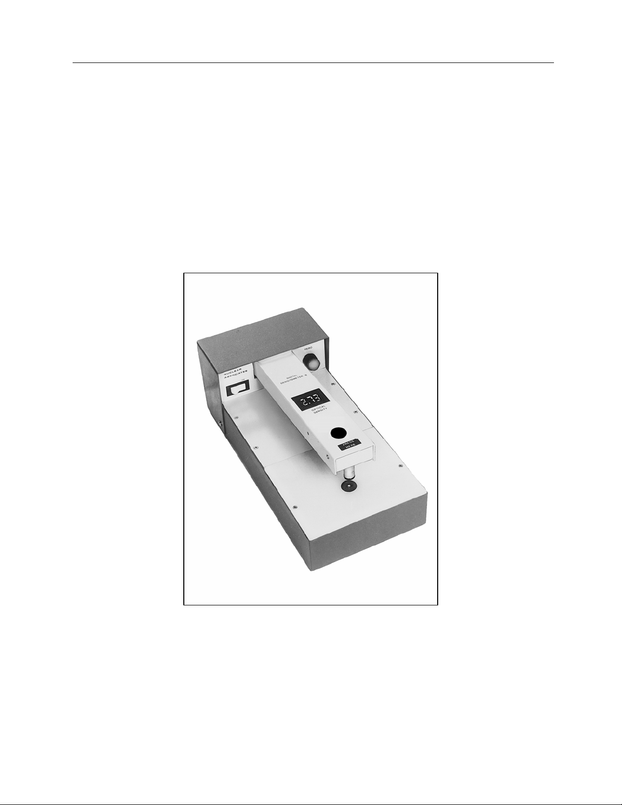
The Model 07-424 Digital Densitometer is designed to measure black/white transmission density with high
accuracy and reliability. With minimum training, an operator can make the precise, repeatable
measurements necessary for accurate photographic film exposure and processing control. Solid-state
dependability together with rugged construction makes the unit exceptionally stable over long periods.
Due to the dependability and construction of the instrument, maintenance requirements are minimal.
Figure 1-1. Digital Densitometer II, Model 07-424
1-1
Page 6

Nuclear Associates 07-424
Operators Manual
1-2. Specifications
Table 1-1. Instrument Specifications
Feature Specifications
Density Range: 0-4.50
Response Time: 2 seconds or faster at optical density 3.00
Warm-Up Time: 10 seconds maximum
Accuracy: +0.02 at density of 3.00 with 1 mm aperture
Density Subtraction: Zero control permits density subtraction of up to 4.50 with 3 mm aperture.
Minus sign included on display to show negative relative densities.
Zero Control: 10-turn control permits exact zeroing with flashing minus sign indicating
correct zero to within 0.002.
Zero Drift: Negligible
Spectral Response: Centered at approximately 465 nanometers
Apertures Supplied: 3 mm, 2 mm and 1 mm dia. Aluminum
Throat: 210 mm (8.25 in.)
Illuminated Table Area: 120 x 140 mm (4.75 x 5.5 in.)
Detector: Silicon diode
Detector Light Source: White LED provides extremely long life with minimum spectral and intensity
degradation. Also reduce specimen heating to a minimum.
DESIGNED TO MEASURE DIFFUSE TRANSMISSION
DENSITY PER ANSI SPECIFICATION PH2-1 9-1959.
Readout: Located on measurement arm, three L.E.D. digits with minus sign, 10 mm
(0.4 in.) high
Dimensions: 4.9 in. x 6.3 in. x 13.4 in
(H x W x D) (125 mm x 160 mm x 340 mm)
Weight: 7.5 Ibs. (3.4 kg)
Shipping Weight: 10 Ibs. (4.3 kg)
Power: Switch selectable, 115 VAC, 50/60 Hz, 15W 230 VAC
Unit available: order #07-424-220
Fuses: For 115 VAC use 1.0 A, 250 V, AGC, Fast Acting
For 230 VAC use 0.5A, 250 V, AGC, Fast Acting
Operating Conditions: 10° C - 40° C (50° F to 104° F) Maximum 90% relative humidity, non-
condensing
Accessories Supplied: Four #37 lamps, one extra o-ring light seal, one set of three apertures
1-2
Page 7

Operation
Setup for Operation
Section 2
Operation
2.1 Setup For Operation
1. Remove the packing material and the tape that secures the measuring arm. Locate the two (2)
plastic envelopes that have been shipped with the instrument. The first contains one (1) #37 lamp,
and an o-ring. The second contains three (3) apertures; 1, 2 and 3 mm. Remove the apertures to
be used for measurement.
2. Plug the instrument into an appropriate receptacle. Voltage may vary from 100 to 130 V (200 to 260
V) without affecting the accuracy of the readings.
3. Turn the power switch to ON. The display should indicate all digits and the table should be
illuminated.
4. Place the 3 mm aperture in position under the photohead in the depression over the filter light
source WITH THE FLAT SIDE UP. Now press the arm down in firm contact with the aperture by
placing your hand on the PRESS HERE area of the arm. The display should read 0.010 to 0.20
(positive), with the ZERO control fully counter-clockwise. Now zero the unit by turning the ZERO
control clockwise until the minus sign (located just above the left hand digit) flashes on and off. This
indicates an exact zero condition.
2
2.2 Operation
1. Select the proper aperture (small flat side UP).
2. Set the ZERO control.
3. Place the film over the aperture with the emulsion side up.
4. Press down on the arm, as indicated, and read optical density on the digital display for high
densities and/or small apertures, it may take a second or two for the reading to reach equilibrium.
5. Density Subtraction
that it reads zero (flashing minus sign) over one film area, then reading a second film area. The
relative density, positive or negative, of the second area measured, will be indicated on the display.
5. On all subsequent readings, check the ZERO before reading a density. While the zero drift is small,
a routine check prevents the possibility of an incorrect value, if, for example, the ZERO knob has
been accidentally disturbed.
: You may find the difference in two densities by turning the ZERO control so
2-1
Page 8

Nuclear Associates 07-424
Operators Manual
(Blank page)
Page 9

Maintenance & Calibration
Precautions
Section 3
Maintenance & Calibration
3.1 Precautions
As with any precision measurement instrument, certain precautions and periodic maintenance are
necessary.
1. Routing Cleaning:
3
Do not immerse the Model 07-424 Digital
Densitometer. The unit is not waterproof. Liquid
could damage the circuits. The unit should be kept
cleaned free from dirt and contamination. The unit
may be cleaned by wiping with a damp cloth using
any commercially available cleaning or
decontaminating agent.
Keep the underside of the photo head clean using
alcohol and a soft cloth as required.
DO NOT USE (UNDER ANY CIRCUMSTANCES)
ANY OTHER SOLVENT.
2. Periodically check the alignment of the aperture and the photohead, especially if the instrument has
been dropped. Inherent mechanical design makes this alignment check easy. Simply remove the
aperture in use with your fingernail and press down on the arm. The o-ring light seal should fit
exactly into the depression normally occupied by the aperture. If the arm is out of alignment, refer to
Section 3.2 for instructions on realignment.
3. If the instrument is used to measure halftones, the 3 mm aperture should be used to reduce the
effect of sampling area. Take into consideration the effects of the maximum density of silver in the
dots and fringes around the dots. Avoid comparing a soft edged dot film with a hard-edged dot film.
CAUTION
3-1
Page 10

Nuclear Associates 07-424
Operators Manual
3.2 Aperture Alignment
Normally the densitometer will operate for a long period of time with little or no maintenance. However, a
periodic check should be made to ensure top performance. The following procedures should be done
yearly.
Check aperture alignment as described in Section 3.1, step 2. If any misalignment is noted, correct it as
described below.
1. Unplug the power cord.
2. Remove the top rear cover by taking out the four (4) screws securing it to the base.
3. Using a 5/32-inch (4 mm) Allen hex wrench, loosen the three (3) screws at the rear of the arm
spring, one complete turn.
DO NOT LOOSEN THE THREE (3) SCREWS ON
THE ARM ITSELF.
4. First inspect the o-ring for damage. If it is, replace it. The push the arm down, with the aperture
removed, until the o-ring is exactly centered in the aperture holder.
5. Tighten the three (3) spring screws, alternately, a quarter turn at a time, until they are fast, while still
holding the arm down.
6. The arm should now be exactly aligned.
NOTE
3.3 Calibration
A calibrated quality control step tablet, P/N 010128, is supplied with the instrument. To check long-term
precision of the instrument, the step tablet should be used at least monthly according to the directions on
the envelope. A step tablet is furnished with the instrument at the time of shipment. Factory calibration is
performed so that the instrument and the step tablet are simultaneously calibrated. Although this step
tablet is calibrated with high accuracy, its primary use is to check for any drift in the instrument supplied
with the step tablet.
If the instrument is to be calibrated using another standard calibration step tablet such as Eastman Kodak
#3 (Catalog Model No.07-460), the following considerations should be taken into account.
2. Use a 3 mm aperture and plot indicated readings versus readings on the calibration sheet supplied
with the tablet. The slope of this line should be exactly 1.00.
3. Using a small screwdriver, adjust the CAL until the desired calibration is achieved. This can be
done by drawing the best straight line through the plotted points, with the origin at zero and noting
the correction necessary at, for example, a density near 2.50.
4. Put the tablet on a step reading close to 2.50 and adjust the CAL control until the desired correction
has been made, such as increasing the indicated reading +0.02.
The calibration method is necessary due to the inaccuracy inherent in even the best calibrated step
tablets. Eastman Kodak rates the accuracy of their #3 Step Tablet calibration at +0.01 or 3% of indicated
density, whichever is greater. Thus with a perfect densitometer, the errors on a brand new tablet (with no
emulsion flaws or wear), would be as shown in Table 3-1.
3-2
Page 11

G
3.4 Lamp Replacement
Maintenance & Calibration
Lamp Replacement
3
WARNIN
Disconnect the unit from the power supply before
removing cover or changing fuses.
3.4.1 Table Lamps
The four (4) #37 lamps which provide table illumination have a life expectancy of approximately 1500
hours. #74 lamps can be used in their place to provide greater brilliancy, but average life is only about
500 hours. Use the following procedure to replace the lamps:
1. Remove the two (2) screws holding the plastic table to the case.
2. Carefully lift out the table using the finger slots provided on either side.
3. The lamps will be clearly visible and, being of the wedge base type, can be removed by pulling up
on them.
4. Insert the four (4) #37 replacement lamps provided in the spare parts kit supplied at the time of
shipment.
When inserting new lamps, make sure that the wire
contacts are in proper position, otherwise good
contact will not be made.
NOTE
Table 3-1. Step Tablet Accuracy
Tablet Density Total Tablet Error
0.10 0.01 0.02
0.30 0.01 0.02
0.50 0.02 0.03
1.00 0.03 0.04
1.50 0.05 0.06
2.00 0.06 0.07
2.50 0.08 0.09
3.00 0.09 0.10
3.50 0.11 0.12
Total Error Assuming
Instrument Error ± 0.01
3-3
Page 12

Nuclear Associates 07-424
G
Operators Manual
3.4.2 Measurement Light Source
Disconnect the unit from the power supply before
removing cover or changing fuses.
The LED used for photometric measurements is P/No. 65-158. This LED should have an extremely long
life. If the LED requires replacement, use the following procedure:
1. Remove the two (2) screws holding the plastic table to the case.
2. Carefully lift out the table using the finger slots provided on either side.
3. Pull off the tabs attached to the wires of the measurement from the printed circuit board.
WARNING
NOTE
It is best to use pliers on the tabs while pushing
down on the printed circuit board.
4. Loosen the screw holding the LED Socket Assembly in the LED/aperture holder and remove the
LED Socket Assembly (see Figure 3-1).
Figure 3-1. LED/Socket Assembly
5. Replace with a new LED, being careful to tighten the LED/Aperture Holder screw only enough to
hold the LED Socket Assembly in place. When the LED is properly positioned vertically, it will
almost touch the aperture in the holder.
6. Return the light table top to its position on the board and fasten it in place.
WARNIN
This instrument contains CMOS Integrated circuits.
No service should be attempted unless by a
qualified technician thoroughly familiar with CMOS
devices. Static charges normally present in a dry
atmosphere or leakage current in soldering irons or
other non-grounded tools can instantly destroy
CMOS integrated devices. Do not attempt to
remove or replace any IC sockets without
3-4
Page 13

Maintenance & Calibration
Lamp Replacement
3
observing anti-static and leakage current
precautions.
3.5 Recommended spare parts
Recommended spare parts are listed below. Table 3-1 provides a parts lists for the Main Board Assembly
and the RS-232 Interface Board Assembly, respectively. Figure 3-1A and 3-1B (RS-232C Interface Board
Schematic Diagram), and Figure 3-2 (RS-232C Interface Board Component Layout) are provided for
reference.
Description
Table Lamps, #37 680011
Measurement LED 65-158
LED Socket Assembly 112327
O-ring, Light Seal 0960013
Aperture Set, l ea. 1, 2 & 3 mm 112023
Fuse for 115 VAC, 1 A, AGC, 760001
Fuse for 230 VAC, 0.5 A, AGC, 760004
Part No.
3-5
Page 14

Fluke Biomedical
Radiation Management Services
6045 Cochran Road
Cleveland, Ohio 44139
440.498.2564
www.flukebiomedical.com/rms
 Loading...