

Page 1

Nuclear Associates
06-526 & 06-526-2200
RAD-CHECK™ PLUS
March 2005
Manual No. 136201 Rev. 5
©2003, 2005 Fluke Corporation, All rights reserved. Printed in U.S.A.
All product names are trademarks of their respective companies
Operators Manual
Page 2

Fluke Biomedical
Radiation Management Services
6045 Cochran Road
Cleveland, Ohio 44139
440.498.2564
www.flukebiomedical.com/rms
Page 3

Table of Contents
Section 1: General Information................................................................................... 1-1
1.1 Product Description ..................................................................................... 1-1
1.2 Specifications ...........................................................................................................1-2
1.3 Manual Addenda ......................................................................................................1-3
1.4 Customer Service/Technical Assistance ..................................................................1-3
Section 2:
2.1 Exposure Mode ........................................................................................................2-1
2.2 Exposure Rate Mode................................................................................................2-3
2.3 Optional Remote Detector Operation .......................................................................2-3
2.4 Applications ..............................................................................................................2-4
2.5 Radiographic Output (mR/mAs) Dose Measurements .............................................2-4
2.6 Determining Minimum Filtration Requirements (Beam Quality - HVL) .....................2-5
2.7 mAs Reciprocity .......................................................................................................2-6
2.8 Fluoroscopic Exposure Rate ....................................................................................2-6
2.9 Accuracy Considerations..........................................................................................2-7
2.9.1 Electrometer Drift................................................................................................2-7
2.9.2 Air Density Corrections.......................................................................................2-7
2.10 Sources of Error .....................................................................................................2-10
2.11 Precautions ............................................................................................................2-10
2.12 Operational Checks................................................................................................2-11
2.13 Drift Rate ................................................................................................................2-11
2.14 Battery Voltage.......................................................................................................2-11
2.15 Zero Set..................................................................................................................2-11
Section 3: Maintenance ............................................................................................... 3-1
3.1 Introduction...............................................................................................................3-1
3.2 Cleaning the Instrument ...........................................................................................3-1
3.3 Circuit Description (General) ....................................................................................3-1
3.4 Auto Reset (Dose Mode)..........................................................................................3-1
3.5 VRM Display.............................................................................................................3-2
3.6 Calibration and Adjustments.....................................................................................3-2
3.7 Zero (R33) ................................................................................................................3-3
3.8 Offset (R30, U4) .......................................................................................................3-3
3.9 Rate Calibration (R25)..............................................................................................3-3
3.10 Auto-Reset (R9) .......................................................................................................3-3
3.11 Remote Detector Calibration ....................................................................................3-3
3.12 Troubleshooting........................................................................................................3-4
3.13 Replacement Parts...................................................................................................3-4
3.14 Return Authorization.................................................................................................3-5
3.15 Protecting Your Warranty .........................................................................................3-5
Operation.................................................................................................... 2-1
i
Page 4

(Blank page)
Page 5
General Information
Product Description
Section 1
General Information
1.1 Product Description
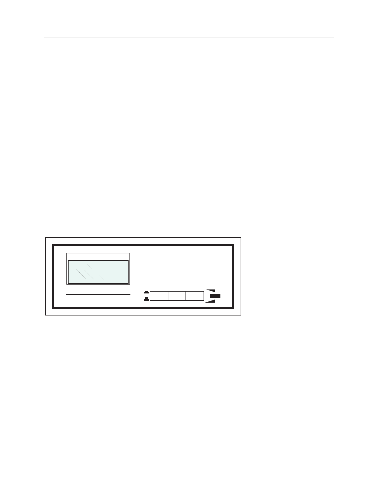
The RAD-CHECK™ PLUS (see Figure 1-1) is a battery operated, portable unit which measures the
output radiation of diagnostic x-ray equipment. The exposure is displayed on a 3 1/2 digit liquid crystal
display (LCD) as either:
1. Exposure, in Roentgens (0.001 to 1.999 R) or SI units of milligrays (0.01 to 19.99 mGy).
2. Rate, in Roentgens per minute (0.01 to 19.99 R/min) or Si units of milligrays per minute (0.1 to
199.9 mGy/min).
Radiation is detected with an internal ionization chamber, or with an optional remote ionization chamber
(part number 6000-528 or 6000-529).
1
The optional detectors consist of an ionization chamber and a 15-foot cable assembly. They are
designed to be used with the RAD-CHECK PLUS for measuring dose and dose rates from diagnostic xray machines. They can also be used with any properly configured charge measuring electrometer.
MODEL 06-526
EXPOSURE-R RATE-R/min
RAD-CHECK™ PLUS
Figure 1-1. RAD-CHECK PLUS X-ray Exposure Meter
RATEON RESET
DOSEOFF
1-1
Page 6
Nuclear Associates 06-526 & 06-526-2200
Operators Manual
1.2 Specifications
RAD-CHECK PLUS
Range Dose 0.001 to 1.999 R (.01 to 19.99 mGy)
Range Rate 0.01 to 19.99 R/min (0.1 to 199.9 mGy/min)
Measurement Area 18.3 cm2 (4.8 in Ø) effective
Standard Calibration
Chamber Bias Supply 270 V
Reproducibility Short term within 1% of full scale
Energy Response 5% from 30 kVp to 150 kVp
Electrometer Drift < 1 mR/min
Maximum
Instantaneous
Exposure Rate
Reset Switch ±1 mR of zero
Power Supply
Display 3 1/2 digit LCD; 1/2 inch high digits; low battery indication
Operating Conditions 10° to 40° C (50° to 104° F)
Relative Humidity 90%, non-condensing
Dimensions 6 (w) x 6.3 (d) x 2.5 in (h) (154 x 160 x 64 mm)
Weight 1.1 lbs (500 g)
5% at 75 kVp with 4 mm Al filtration at 22° C (72° F) and one
atmosphere - 760 mm of Hg
20 R/sec
9 V alkaline battery (Duracell type MN 1604 or equivalent). 50 hour
operation in manual or external mode; 100 hour operation in auto
mode
Optional External Detectors (Part No. 6000-528 (30 cc) & 6000-529 (3 cc Mammo))
Radiation
Measurement
Nominal Sensitivity
Volume
Energy Response
Wall 0.031 inch phenolic
Termination Signal; coaxial, fully guarded BNC HV; recessed banana plug
Cable Length 15 feet
Dimensions
* Specifications are subject to change without notice.
Model 6000-528: x-rays from 30 to 150 kVp
Model 6000-529: x-rays from 16 to 90 kVp
Model 6000-528: 9 nC/R
Model 6000-529: 1 nC/R
Model 6000-528: nominal 30 cc
Model 6000-529: nominal 3 cc
Model 6000-528: 30 to 150 kVp, within 7%
Model 6000-529: 16 to 90 kVp, within 7%
Model 6000-528:
4 (w) x .54 (d) x 4 in (h) (101.6 x 13.7 x 101.6 mm)
Model 6000-529:
1.57 inch Ø x .54 inch deep (40 mm x 15 mm)
1-2
Page 7

General Information
Manual Addenda
1.3 Manual Addenda
Any improvements or changes concerning the instrument or manual will be explained in an addenda
included with the manual. Be sure to note these changes and incorporate them into the manual.
1.4 Customer Service / Technical Assistance
Should you require operation or application assistance or service of your instrument, contact Fluke
Biomedical, Radiation Management Services at 440.248.9300.
1
1-3
Page 8

Nuclear Associates 06-526 & 06-526-2200
Operators Manual
(Blank page)
Page 9

Operation
Exposure Mode
2
Section 2
Operation
WARNING
Extreme caution should be used when making
connections with the chamber and rear panel
connectors.
An electrical shock hazard exists between the ion
chamber bias connector and ground (HV Out).
WARNING
2.1 Exposure Mode
1. Turn the power switch to the ON position.
NOTE
RAD-CHECK PLUS performs to the specifications
immediately on application of power. However, a
five-minute warm-up period is suggested to
minimize the drift associated with surface charge
distribution.
a. If LOW BAT appears in the upper left corner of the display, the battery voltage is low. Refer to
the Battery Voltage section for battery replacement procedures.
b. If no display is present, the battery may be fully discharged. Refer to the Battery Voltage
section for battery replacement procedures.
2. Set the front panel selector switch to DOSE.
3. Set the rear panel switch to the desired position, refer to Figure 2-1:
a. Select the manual (MAN) position if automatic reset is not desired or x-ray intensity is too low
for auto reset.
NOTE
When the rear panel switch is set to the manual
position, the display must be reset, using the front
panel button, after each exposure.
b. Select the (AUTO) position if automatic reset of the electronic circuit is desired after each
exposure. Minimum operating parameters are discussed later in this section.
2-1
Page 10

Nuclear Associates 06-526 & 06-526-2200
Operators Manual
c. Select the external detector (EX DET) position if using the remote ion chamber (part number
6000-528). (Other ion chambers may be read if the proper connection is made. The RADCHECK PLUS provides a 270 V chamber bias for this purpose.)
NOTE
When the rear panel switch is set to the EX DET
position, the display must be reset, using the front
panel button, after each exposure. The internal ion
chamber is still connected when the switch is set to
the EX DET position. Be sure to keep the internal
ion chamber out of the radiation beam when using
an external chamber.
4. Using the collimator light field, adjust the field size to 6 inch (15 cm) in diameter (i.e. the size of the
RAD-CHECK PLUS case).
5. Position the instrument so that the primary beam is centered on, and perpendicular to, the detector
(represented by the black disk on top of the unit). For under-table tubes, invert the RAD-CHECK
PLUS so that the detector faces the x-ray tube.
6. Press the RESET button to zero the display; make the x-ray exposure.
NOTE
It is not necessary to press the RESET button when
the rear panel switch is in the AUTO position.
7. Read the exposure in roentgens (R). To minimize drift effects, readings should be recorded
immediately.
CAUTION
If the display does not update, and the unit is in the
AUTO mode, press the front panel RESET button.
Select a higher kVp or mA, or use the manual reset
mode, and make another exposure.
REMOTE
CHAMBER
INTER (MAN)
INTER (AUTO)
EX DET
ZERO
CAUTION: DO NOT CHANGE SWITCH
POSITION WITH POWER ON
HV
CAUTION: TURN OFF
POWER SWITCH BEFORE
REPLACING BATTERY.
USE MN1604 OR EQUIV.
ALKALINE BATTERY.
136058
Figure 2-1. Rear Panel
2-2
Page 11

Operation
Exposure Rate Mode
2.2 Exposure Rate Mode
1. Turn the power switch to the ON position.
NOTE
RAD-CHECK PLUS performs to the specifications
immediately on application of power. However, a
five-minute warm-up period is suggested to
minimize the drift associated with surface charge
distribution.
a. If LOW BAT appears in the upper left corner of the display, the battery voltage is low. Refer to
the Battery Voltage section for battery replacement procedures.
b. If no display is present, the battery may be fully discharged. Refer to the Battery Voltage
section for battery replacement procedures.
2. Set the front panel selector switch to RATE.
3. Set the rear panel switch to either the MAN or EX DET position. The AUTO position is not used in
the rate mode.
NOTE
When operating in the exposure rate mode,
pressing the RESET button is not necessary. Be
sure to keep the internal ion chamber out of the
radiation beam when using an external chamber.
4. Using the collimator light field, adjust the field size to 6 inch (15 cm) in diameter (i.e. the size of the
RAD-CHECK PLUS case).
5. Position the instrument so that the primary beam is centered on, and perpendicular to, the detector
(represented by the black disk on top of the unit). For under-table tubes, invert the RAD-CHECK
PLUS so that the detector faces the x-ray tube.
6. Energize the x-ray equipment.
7. Read the exposure rate in roentgens per minute (R/min). To minimize drift effects, readings should
be recorded immediately.
2
2.3 Optional Remote Detector Operation
To use the remote detector:
1. Connect the remote cable to the rear panel connectors.
a. The coaxial BNC on the chamber body is the signal input.
b. The recessed banana plug is the high voltage connection for the chamber bias.
c. The middle receptacle is threaded with a standard 1/4-20 thread for accessory mounting.
2. Set the rear panel selector to EX DET.
3. Turn the unit ON.
2-3
Page 12

Nuclear Associates 06-526 & 06-526-2200
Operators Manual
NOTE
Be sure not to pinch or crush the cable as this may
cause an error in the readings. Keep the internal
chamber out of the radiation beam. Internal
chamber is still connected to the electrometer.
4. Using the collimator light field, adjust the field size to 15 cm (6 in) in diameter (i.e. the size of the
RAD-CHECK PLUS case).
5. Position the instrument so that the primary beam is centered on, and perpendicular to, the detector
(represented by the black disk on top of the unit). For under-table tubes, invert the RAD-CHECK
PLUS so that the detector faces the x-ray tube.
6. Press the RESET button to zero the display; make the x-ray exposure.
7. Read the exposure roentgens (R) or the exposure rate (R/min). To minimize drift effects, readings
should be recorded immediately.
WARNING
When finished, turn the unit OFF before
disconnecting the cables to the remote detector.
2.4 Applications
RAD-CHECK PLUS can be used to measure radiation output as required by quality assurance
procedures. Several applications are discussed in the following paragraphs.
In each of these applications, it is important that all data pertaining to tests performed be recorded for
later comparison. Records should include the date, technique factor used, and readings obtained.
2.5 Radiographic Output (mR/mAs) Dose Measurements
1. Set up the x-ray field as follows:
a. Using the collimator light field, adjust the field size to 6 x 6 inch (15 x 15 cm). This adjustment
is equal to the size of the RAD-CHECK PLUS case.
b. Position the instrument so that the primary beam is centered on, and perpendicular to the
detector (represented by the black disk on top of the unit).
2. Select the desired x-ray technique (kVp, mA, and time).
3. Make the exposure.
4. Record the mR reading.
5. Calculate the mR/mAs value.
6. Record the value calculated in Step 5 and the technique factors selected in Step 2 (for reference at
a later date).
2-4
Page 13

Operation
Determining Minimum Filtration Requirements (Beam Quality-HVL)
2
2.6 Determining Minimum Filtration Requirements (Beam Quality HVL)
1. Select a tube potential which is commonly used and is in the highest kVp range of the x-ray
machine. Refer to Table 2-1.
2. Position the x-ray tube and the RAD-CHECK PLUS.
3. With no added filtration in the beam, make an exposure and record the reading.
4. Using the optional Half-Value Layer Kit (or equivalent), tape the increments of filtration to the face
of the collimator.
5. Make an exposure and record the reading for each total thickness of filtration as indicated in Table
2-1.
The information contained in Table 2-1 was
extracted from DHEW Publications (FDA) 76-8014
"Suggested Optimum Survey Procedures for
Diagnostic X-Ray Equipment."
6. Plot the exposure reading (log Scale) verses the total added filtration thickness on semilog paper.
7. Determine the exposure value which is 50% of the radiation recorded in Step 3. The corresponding
thickness is the HVL value. Refer to Table 2-1 for the minimum HVL values required for that
particular kVp.
To check the minimum filtration requirement at a particulate kVp:
NOTE
1. At a pre-selected kVp, record an exposure reading with no filtration.
2. Record an exposure reading with the minimum filtration requirement taped to the collimator.
The minimum filtration required has been met if the second exposure is less than or equal to one-half of
the first reading.
Table 2-1. Minimum Filtration Requirements
kVp Range
Below 50 0.5, 1.0, 1.5, 2.0 30 0.3
40 0.4
49 0.5
50 to 70 1.0, 1.5, 2.5, 3.5 50 1.2
60 1.3
70 1.5
Above 70 1.5, 2.5, 3.5, 4.5 71 2.1
80 2.3
90 2.5
100 2.7
110 3
120 3.2
Total added filtration
steps (mm Al)
kVp
Measured
HVL
(mm Al)
2-5
Page 14

Nuclear Associates 06-526 & 06-526-2200
Operators Manual
130 3.5
140 3.8
150 4.1
2.7 MAS Reciprocity
At any given kVp, combinations of time and mA that yield equal mAs values should produce equal
exposure (output) values.
1. Make an exposure at each mA station, varying the time to maintain mAs constant. Do not adjust
kVp.
2. Record the exposure value obtained.
Variations exceeding the 10% average value may indicate the need for equipment re-calibration.
2.8 Fluoroscopic Exposure Rate
1. Position the RAD-CHECK PLUS with the detector circle facing the x-ray tube (inverted for undertable tubes).
2. Using the optional 07-706 Patient Phantom (or equivalent), place two 3/4 inch aluminum
attenuators between the RAD-CHECK PLUS and the image intensifier.
3. Center the detector in the fluoroscopic beam as follows:
a. Turn on the x-ray beam at a low mA setting.
b. Use the image intensifier to view the RAD-CHECK PLUS image.
c. Press the RATE button on the RAD-CHECK PLUS front panel.
d. Turn the fluoroscope on and read the display.
To prevent damage to the image intensifier, the
aluminum attenuators must be in place while
making an exposure.
4. Place a 1/8 inch lead beam stop plate (also included in the 07-706 Patient Phantom) or equivalent
(folded lead apron) between the RAD-CHECK PLUS and the image intensifier tube. This drives the
automatic brightness control to maximum output.
On equipment without automatic brightness
controls, select maximum output settings.
21CFR1020 requires that the maximum exposure
rate be less than 10 R/min (Cg/min).
CAUTION
NOTE
2-6
Page 15

Operation
Accuracy Considerations
2
2.9 Accuracy Considerations
2.9.1 Electrometer Drift
Each instrument has a constant drift which can be measured in a zero radiation field. Drift is expressed
as mR/min and has a typical value of 1 mR/min or less. By recording the drift rate, this error can be
corrected. Refer to Table 2-2. Drift of the internal chamber can only be measured in the manual mode.
2.9.2 Air Density Corrections
Temperature and pressure have a definite effect on the response from the ion chamber; they determine
the number and density of molecules present for ionization. Figure 2-2 shows the correction factors used
for changes in temperature and altitude (from 22°C and sea level). To achieve maximum accuracy, use
the following equation:
Corrected Exposure =
(Measured Exposure - Drift x Exposure Time) (CF
Where CTT and CFP are the correction factors for temperature and pressure respectively. Note that no
more than 2% errors result over the temperature range of 60° to 82°F (16° to 28°C), so that the
temperature correction can normally be disregarded.
) (CFP)
T
In the above equation, CF
= T(°C) + 273
CF
T
295
= 760
CF
P
P(mm Hg)
Where:
T(°C) = temperature measured in degrees C, and
P (mm Hg) = pressure measured in mm Hg
and CFP can be calculated (rather than approximating using Figure 2-2).
T
2-7
Page 16

Nuclear Associates 06-526 & 06-526-2200
Operators Manual
Table 2-2. Periodic Drift Rate Record
Date Drift (mR) Time (Min) Rate (mR/Min)
* / /
* The first reading is performed at the factory for future references over the life of the instrument.
Figure 2-2. Temperature Altitude Correction Graphs
2-8
Page 17

A
Maximum Threshold for Automatic Reset
Typical 1 Phase mAs Required
(May vary on different machines)
40 80 120
18"
keV
24"
30"
Figure 2-3. Auto Reset Technique Requirements
1.2
1.1
Correction
Factor
1.0
0.9
.2 .3 .4 .5 .6 .7 .8 .9 4321
HVL - mmAl
= 20 kV
= 40 kV
= 30 kV
= 50 kV
Figure 2-4. Energy Dependence
60 kV
200
100
50
20
m
75 kV
Operation
Accuracy Considerations
Calibration
Point
2
2-9
Page 18

Nuclear Associates 06-526 & 06-526-2200
Operators Manual
2.10 Sources of error
If an incorrect measurement is suspected, check the items listed below as they are potential sources of
error:
1. Low battery voltage.
2. Failure to properly zero the unit before/between measurements.
3. Uncorrected drift error over long exposure times.
4. Unusual atmospheric conditions requiring a correction factor.
5. External low energy backscatter.
6. Capacitive effects (see precautions).
7. Static discharge (see precautions).
8. If using the remote detector, a damaged cable or connector.
9. Operating the unit beyond specified limits of temperature, x-ray energy, etc.
2.11 Precautions
CAUTION
Due to the high voltage inside the ion chamber and
its delicate nature, puncturing or removing the
chamber cover may result in damage to the unit or
a change in calibration.
CAUTION
If a large amount of static electricity is present,
small to moderate absolute errors may occur as a
result of touching the exposed window. This is
most likely to occur when the ambient humidity is
very low.
CAUTION
Because of the highly sensitive nature of the
electrometer input circuit, changing the position of
the instrument can cause small changes in the
reading due to capacitive effects. This is a
reversible error and can be corrected by returning
the unit to its original position or manually resetting
the unit.
2-10
Page 19

Operation
Accuracy Considerations
CAUTION
Exposures in the AUTO mode which do not trigger
the reset will accumulate in the electrometer until a
reset occurs either from a proper exposure or
manually. If exposure reset occurs, the display will
include the most recent exposure and the
accumulated exposures which
did not reset.
2
2.12 Operational Checks
Regular monitoring of the instrument's performance is necessary to achieve maximum accuracy.
2.13 Drift Rate
Periodic measurements of the drift rate should be recorded for reference when long exposure periods are
used. Refer to Table 2-2.
2.14 Battery Voltage
Correct battery voltage is important for proper operation of the unit. Installation and replacement of the
battery requires the removal of the rear access panel. Refer to Figure 2-1. A MN1604 alkaline battery
(P/N 16-29 or equivalent) is recommended. However, any standard 9 V transistor battery will work, but
with shorter life. The battery should be replaced after a maximum of one year's use.
Turn the unit off before replacing the battery.
WARNING
2.15 Zero Set
Due to aging of circuit components, small changes in the zero reading can be expected over the lifetime
of the unit. A Zero adjustment, located on the rear panel, is provided to permit field adjustment as follows:
1. Turn the unit ON.
2. Wait five minutes.
3. Set the front panel switch to DOSE.
4. Set the rear panel switch to MAN.
5. Press RESET.
6. Adjust ZERO if necessary so that the display shows 0.000.
2-11
Page 20

Nuclear Associates 06-526 & 06-526-2200
Operators Manual
(Blank page)
Page 21

Maintenance
Introduction
3
Section 3
Maintenance
3.1 Introduction
The RAD-CHECK PLUS contains three functional elements: the ion chamber, the electrometer circuit,
and the Voltage Ratio Module (VRM).
The ion chamber consists of electricity charged plates enclosing a constant volume. Under manual
operation (no radiation), no free ions exist in this volume. When exposed to an ionization source, ions are
created in direct relationship to the field strength. The ions are collected, producing an output current.
3.2 Cleaning the Instrument
Do not immerse the Model 06-526, 06-526-2200. The unit is not waterproof. Liquid could damage the
circuits. The unit should be kept clean and free from dirt and contamination. The unit may be cleaned by
wiping with a damp cloth using any commercially available cleaning or decontaminating agent.
3.3 Circuit Description (General)
The electrometer circuit is either a charge integration circuit or a current to voltage circuit depending on
the selection of DOSE or RATE respectively.
The DOSE or RATE mode is selectable using the front panel switch. When operating in the DOSE mode,
the electrometer circuit is a charge integration circuit. When operating in the RATE mode, the
electrometer circuit is a current to voltage converter.
Use care 270 VDC is present inside the unit
WARNING
3.4 Auto Reset (DOSE Mode)
When the rear panel switch is placed in the AUTO RESET position, diode D8 is active; radiation causes a
current to flow through D8. This current produces a voltage which is input to voltage a comparator.
When the threshold is exceeded, the comparator changes its output state causing comparator U1B to
change state. U1B turns on transistor Q1 which closes relay RR2. RR2 remains closed as long as
radiation is present.
When radiation is removed, RR2 opens and one-shot multivibrator U2A/U2B pulses RR2 to discharge
C11. This sets up the integrator for the next shot. In manual or external modes, D6 and R13 bypass the
auto reset and RR2 remains closed.
3-1
Page 22

Nuclear Associates 06-526 & 06-526-2200
Operators Manual
The high voltage utilized by the ion chamber is generated by the blocking oscillator circuit comprised of
Q4 and associated components. Zener diode CR3 determines the output voltage thus enabling the circuit
to be less sensitive to changes in input voltage.
The electrometer and the blocking oscillator operate from an internal +5 V supply generated by U5.
Transistor Q3 detects low battery voltage and turns on the LOW BAT display through R36.
U3 is a buffer for C13 that retains the last output of U4 through R32. The output of U3 is displayed on the
VRM through selection of the DOSE switch position (SW2B). R33 is the zero (offset) adjustment for U4.
CR1 provides a 1.2 V reference for the digital display VRM (at pin 7).
3.5 VRM Display
The voltage ratio module consists of an auto-zeroing, dual-slope analog to digital converter and a 3 1/2
digit liquid crystal display (LCD). The VRM converts two independent voltages into a display reading
representing the ratio of the two voltages:
Display = (IN HI - IN LOW)
(RFH-RFL)
Because of the compact nature of the VRM board, it should be completely replaced if defective, rather
than attempting repairs.
3.6 Calibration and Adjustments
This instrument has been calibrated to ± 5% at 75 kVp with 4 mm Al filtration at 72°F (22°C) and 760 mm
of Hg (one atmosphere).
The user should be aware that changes in altitude
and temperature will affect the reading (refer to Air
Density Corrections in Section 2).
The voltages listed below should be checked before continuing with adjustments or calibrations.
1. TP6 - TP8 = + 7 to + 9 V
2. TP6 - TP9 = + 5 V ± 0.5
3. TP12 - TP10 = - 270 V ± 10% (use an electrostatic voltmeter)
3. TP6 - TP4 = 1.1 V ± 0.2 V (see the adjustment for R19 for information)
The control functions are discussed in the following paragraphs. Refer to the internal circuit board for
component locations.
NOTE
3-2
Page 23

3.7 Zero (R33)
This adjustment eliminates offset and aging errors common to operational amplifiers.
1. With the cover on the unit, set the front panel switch to DOSE.
2. Set the rear panel switch to MAN.
3. Reset the display, observe for several minutes, and adjust R33 as required.
3.8 Offset (R30, U4)
1. Set the front panel switch to DOSE.
2. Set the rear panel switch to AUTO-RESET.
3. Press the RESET button on the front panel. The display should read 0.00.
4. If necessary, adjust R30 to display a 0.00 reading.
Maintenance
Zero (R33)
3
Use a voltmeter between TP4 and TP9 for
accuracy.
NOTE
3.9 Rate Calibration (R25)
Adjust the rate calibration using a known source.
3.10 Auto-Reset (R9)
Adjust the Auto Reset for 175 mV U1-6, TP13 to GND (TP12).
3.11 Remote Detector Calibration
Calibration of the external detectors can be performed by the user as follows:
1. Set the x-ray machine to 100 kV, 300 mA, 0.5 sec.
Do not exceed tube-rating limit.
2. Position RAD-CHECK PLUS at 40 inches.
3. Measure 5 exposures. Record the average as "True." All five should be within 3%.
4. Connect the external chamber.
5. Set the rear panel selector switch to EX DET.
6. Position the external chamber in the same position and same height (tops of chambers) as the
RAD-CHECK PLUS. Keep internal chamber out of the radiation beam.
7. Move the RAD-CHECK PLUS to the control booth.
CAUTION
3-3
Page 24

Nuclear Associates 06-526 & 06-526-2200
Operators Manual
8. Measure 5 exposures. Record the average as "Measured." All five should be within 3%.
9. Calculate correction factor (cf):
cf = True
Measured
10. Reposition RAD-CHECK PLUS and measure 1 exposure to verify that the x-ray machine did not
change.
All readings on the RAD-CHECK PLUS using the external chamber should be multiplied by the correction
factor. (HINT: Write the correction factor on a small sticker and put it on the chamber.)
3.12 Troubleshooting
WARNING
Extreme caution should be used when making
connections with the chambers and rear panel
connectors.
WARNING
An electrical shock hazard exists between the ion
chamber bias connector and ground (HV Out).
When there is a problem with the unit, refer to the table below for possible causes and corrective action.
Symptom Possible Cause Correction Action
No display &
No reset light
Display ON;
No reading
Inaccurate readings Exposure level too low (see Figure 2-3) Position rear panel selector switch to
Does not zero Adjust rear panel zero (see Zero Set)
Low battery voltage Replace battery
Defective/damaged ion chamber Recalibrate chamber
Dead battery
Broken battery snap lead
Defective ON/OFF switch
Rear panel selector switch positioned
incorrectly
Replace battery
Replace lead
Replace switch
Check and correct switch position
MAN reset position
Return unit to factory for chamber
repair/replacement
3.13 Replacement Parts
Unless otherwise noted, resistors are .25 W, 5% carbon film; non-polarized capacitors are ceramic disk
type, 20% tolerance, 100 VDC; and capacitors marked "FILM" are 10% tolerance, 100 VDC. Non-limited
parts are standard components and should be available through local suppliers.
If it is necessary to order replacement parts, contact Fluke Biomedical at 440.248.9300.
3-4
Page 25

Maintenance
Return Authorization
3.14 Return Authorization
Upon receipt of the unit:
1. Check the shipping cartons(s) and their contents for in-shipment damage. If damage is evident, file
a claim with the carrier and contact Fluke Biomedical at 440.248.9300 immediately.
2. Check that all items listed on the packing slip are present and in good condition. If any items are
missing or damaged, contact Fluke Biomedical at 440.248.9300 immediately.
3.15 Protecting Your Warranty
Should your instrument require warranty service, contact Fluke Biomedical at 440.248.9300.
3
3-5
Page 26

Fluke Biomedical
Radiation Management Services
6045 Cochran Road
Cleveland, Ohio 44139
440.498.2564
www.flukebiomedical.com/rms
 Loading...