

Page 1

05-450
Digital Doorway Monitor
Users Manual
PN 4484936
Rev. 1, April 2014
© 2014 Fluke Corporation. All rights reserved. Specifications are subject to change without notice.
All product names are trademarks of their respective companies.
Page 2

Warranty and Product Support
Fluke Biomedical warrants this instrument against defects in materials and workmanship for one year from
the date of original purchase OR two years if at the end of your first year you send the instrument to a Fluke
Biomedical service center for calibration. You will be charged our customary fee for such calibration. During
the warranty period, we will repair or at our option replace, at no charge, a product that proves to be
defective, provided you return the product, shipping prepaid, to Fluke Biomedical. This warranty covers the
original purchaser only and is not transferable. The warranty does not apply if the product has been
damaged by accident or misuse or has been serviced or modified by anyone other than an authorized Fluke
Biomedical service facility. NO OTHER WARRANTIES, SUCH AS FITNESS FOR A PARTICULAR
PURPOSE, ARE EXPRESSED OR IMPLIED. FLUKE SHALL NOT BE LIABLE FOR ANY SPECIAL,
INDIRECT, INCIDENTAL OR CONSEQUENTIAL DAMAGES OR LOSSES, INCLUDING LOSS OF DATA,
ARISING FROM ANY CAUSE OR THEORY.
This warranty covers only serialized products and their accessory items that bear a distinct serial number
tag. Recalibration of instruments is not covered under the warranty.
This warranty gives you specific legal rights and you may also have other rights that vary in different
jurisdictions. Since some jurisdictions do not allow the exclusion or limitation of an implied warranty or of
incidental or consequential damages, this limitation of liability may not apply to you. If any provision of this
warranty is held invalid or unenforceable by a court or other decision-maker of competent jurisdiction, such
holding will not affect the validity or enforceability of any other provision.
7/07
Page 3

Notices
All Rights Reserved
Copyright 2014, Fluke Biomedical. No part of this publication may be reproduced, transmitted, transcribed, stored in a
retrieval system, or translated into any language without the written permission of Fluke Biomedical.
Copyright Release
Fluke Biomedical agrees to a limited copyright release that allows you to reproduce manuals and other printed materials
for use in service training programs and other technical publications. If you would like other reproductions or distributions,
submit a written request to Fluke Biomedical.
Unpacking and Inspection
Follow standard receiving practices upon receipt of the instrument. Check the shipping carton for damage. If damage is
found, stop unpacking the instrument. Notify the carrier and ask for an agent to be present while the instrument is
unpacked. There are no special unpacking instructions, but be careful not to damage the instrument when unpacking it.
Inspect the instrument for physical damage such as bent or broken parts, dents, or scratches.
Technical Support
For application support or answers to technical questions, either email techservices@flukebiomedical.com or call 1-800850-4608 or 1-440-248-9300. In Europe, email techsupport.emea@flukebiomedical.com or call +31-40-2675314.
Claims
Our routine method of shipment is via common carrier, FOB origin. Upon delivery, if physical damage is found, retain all
packing materials in their original condition and contact the carrier immediately to file a claim. If the instrument is delivered
in good physical condition but does not operate within specifications, or if there are any other problems not caused by
shipping damage, please contact Fluke Biomedical or your local sales representative.
Returns and Repairs
Return Procedure
All items being returned (including all warranty-claim shipments) must be sent freight-prepaid to our factory location. When
you return an instrument to Fluke Biomedical, we recommend using United Parcel Service, Federal Express, or Air Parcel
Post. We also recommend that you insure your shipment for its actual replacement cost. Fluke Biomedical will not be
responsible for lost shipments or instruments that are received in damaged condition due to improper packaging or
handling.
Use the original carton and packaging material for shipment. If they are not available, we recommend the following guide
for repackaging:
Use a double–walled carton of sufficient strength for the weight being shipped.
Use heavy paper or cardboard to protect all instrument surfaces. Use nonabrasive material around all
projecting parts.
Use at least four inches of tightly packed, industry-approved, shock-absorbent material around the
Returns for partial refund/credit:
Every product returned for refund/credit must be accompanied by a Return Material Authorization (RMA) number,
obtained from our Order Entry Group at 1-440-498-2560.
Repair and calibration:
To find the nearest service center, go to www.flukebiomedical.com/service or
In the U.S.A.:
Cleveland Calibration Lab
Tel: 1-800-850-4608 x2564
Email: globalcal@flukebiomedical.com
Everett Calibration Lab
Tel: 1-888-99 FLUKE (1-888-993-5853)
Email: service.status@fluke.com
In Europe, Middle East, and Africa:
Eindhoven Calibration Lab
Tel: +31-40-2675300
Email: ServiceDesk@fluke.com
In Asia:
Everett Calibration Lab
Tel: +425-446-6945
Email: service.international@fluke.com
instrument.
Page 4

To ensure the accuracy of the Product is maintained at a high level, Fluke Biomedical recommends the product
be calibrated at least once every 12 months. Calibration must be done by qualified personnel. Contact your local
Fluke Biomedical representative for calibration.
Certification
This instrument was thoroughly tested and inspected. It was found to meet Fluke Biomedical’s manufacturing
specifications when it was shipped from the factory. Calibration measurements are traceable to the National Institute of
Standards and Technology (NIST). Devices for which there are no NIST calibration standards are measured against inhouse performance standards using accepted test procedures.
WARNING
Unauthorized user modifications or application beyond the published specifications may result in electrical shock hazards
or improper operation. Fluke Biomedical will not be responsible for any injuries sustained due to unauthorized equipment
modifications.
Restrictions and Liabilities
Information in this document is subject to change and does not represent a commitment by Fluke Biomedical.
Changes made to the information in this document will be incorporated in new editions of the publication. No
responsibility is assumed by Fluke Biomedical for the use or reliability of software or equipment that is not
supplied by Fluke Biomedical, or by its affiliated dealers.
Manufacturing Location
The 05-450 is manufactured for Fluke Biomedical, 6920 Seaway Blvd., Everett, WA, U.S.A.
Page 5

Table of Contents
Title Page
Introduction ............................................................................................ 1
Safety Information ................................................................................. 3
Symbols ................................................................................................. 4
General Specifications ....................................................................... 5
Driver Option Specification ........................................................ ........... 6
Getting Started ...................................................................................... 7
Power Up ........................................................................................... 7
Radiation Units .................................................................................. 8
Checking Parameters ........................................................................ 8
Setting Alarm-Points .......................................................................... 9
Operational Check (Optional) ............................................................ 9
Operator Controls and Setup ................................................................ 10
Calibration Controls ........................................................................... 10
Dipswitch (under calibration cover) ................................................... 11
RS-232 Output ................................................................................... 12
9-Pin Data Connector ........................................................................ 13
Detector Setups ................................................................................. 13
Common Options and Modifications...................................................... 14
Time and Date Stamp Option ............................................................ 14
Description ..................................................................................... 14
Setup ............................................................................................. 14
Date and Time ............................................................................... 14
RS232 Data Format ....................................................................... 14
Modifications to the Product for Optimum Performance .................... 14
Calibration ............................................................................................. 15
High Voltage ...................................................................................... 15
Calibration Parameters ...................................................................... 15
Analog Output .................................................................................... 16
Discriminator ...................................................................................... 16
Battery Charge .................................................................................. 16
Receiving and Installation ..................................................................... 17
Unpacking .......................................................................................... 17
Installation ......................................................................................... 17
Location ......................................................................................... 17
Detectors ....................................................................................... 17
Instrument (Counter) ..................................................................... 17
i
Page 6

05-450
Users Manual
Cables ........................................................................................... 17
Optional Remote Alarms ............................................................... 18
Maintenance .......................................................................................... 18
Cleaning Instructions and Precautions .............................................. 18
Replacement of Mains Fuse .............................................................. 18
Detector Connector ........................................................................... 18
Recycling ........................................................................................... 19
Drawings ............................................................................................... 20
ii
Page 7

List of Figures
Figure Title Page
1. Front Panel ................................................................................................ 2
2. Left Side-Panel .......................................................................................... 7
3. Alarm Point Notice ..................................................................................... 8
4. Typical Installation 385x442 ...................................................................... 20
5. Detector Enclosure 385x106 ..................................................................... 21
6. Detector Mounting 385x120 ...................................................................... 22
iii
Page 8

05-450
Users Manual
iv
Page 9

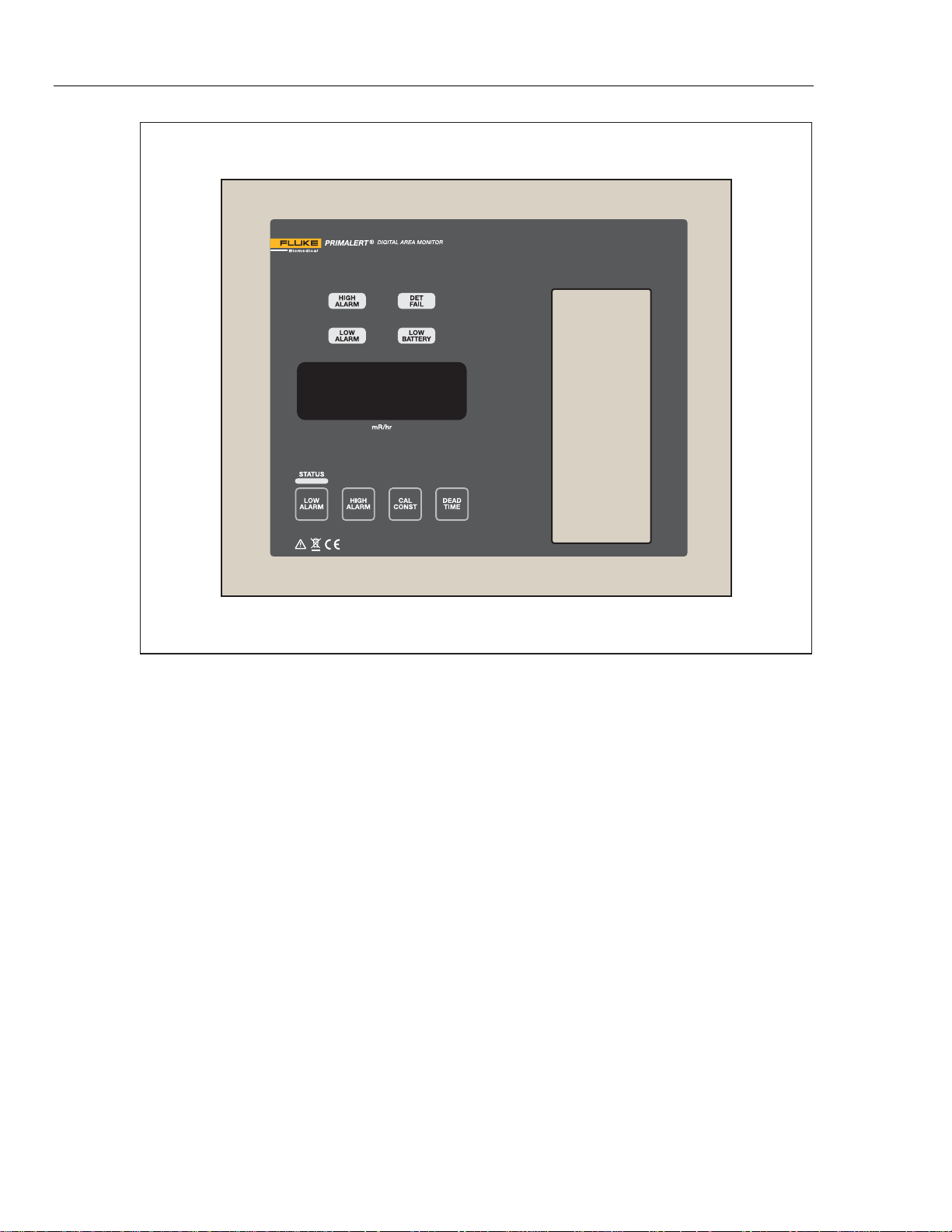
Introduction
Model 05-450 and 05-450-2200 Digital Doorway Monitor (the Product) is
designed to monitor for nuclear radiation. Featuring a wall-mount chassis, the
Product has a four-digit LED display that is readable from 9 m (30 ft) away.
Backlit indicators warn of low radiation alarm (yellow), high radiation alarm (red),
instrument failure (red) and low battery (yellow). A green status light is a positive
indication of instrument operation.
Parameters are protected under a calibration cover. Calibration is easily
accomplished by moving the CAL dipswitch to the right, and using the
pushbuttons to increment or decrement the calibration constant, dead time
correction, and alarm point parameters. Parameters are stored in non-volatile
memory (retained even with power disconnected).
A five-decade logarithmic analog output is provided. A battery backup provides
48 hours of additional use after the primary power is removed.
Note
The detector does not contain any consumable materials.
Note
If the detector is used in a manner not intended by the manufacturer,
the detector may not function properly.
The Product has two scintillation detectors, each with internal lead shield to
reduce background radiation. Detectors may be supplied with or without
environmental enclosures. The scintillation detectors detect low levels of waste
radiation. These detectors are usually, but not always, used in scrap yards or
hospitals. Lead shields around the crystal allows specific coverage areas for
radiation detection. Figure shows the Product.
1
Page 10
05-450
Users Manual
Figure 1. Front Panel
huk01.eps
2
Page 11

Digital Doorway Monitor
Safety Information
Safety Information
A Warning identifies conditions and procedures that are dangerous to the user.
A Caution identifies conditions and procedures that can cause damage to the
Product or the equipment under test.
Warning
To prevent possible electrical shock, fire, or personal injury:
• Read all safety information before you use the Product.
• Carefully read all instructions.
• Do not use the Product around explosive gas, vapor, or in
damp or wet environments.
• Use the Product only as specified, or the protection
supplied by the Product can be compromised.
• Use this Product indoors only.
• Use only the mains power cord and connector approved for
the voltage and plug configuration in your country and
rated for the Product.
• Replace the mains power cord if the insulation is damaged
or if the insulation shows signs of wear.
• Make sure the ground conductor in the mains power cord is
connected to a protective earth ground. Disruption of the
protective earth could put voltage on the chassis that could
cause death.
• Do not put the Product where access to the mains power
cord is blocked.
• Do not operate the Product with covers removed or the
case open. Hazardous voltage exposure is possible.
• Batteries contain hazardous chemicals that can cause
burns or explode. If exposure to chemicals occurs, clean
with water and get medical aid.
• Have an approved technician repair the Product.
• Use only specified replacement parts.
• Do not use the Product if it is damaged.
• Disable the Product if it is damaged.
• Use only specified replacement fuses.
• For continued protection against the risk of fire, replace
only with fuse of the specified type and current rating.
• The operator or responsible body is cautioned that the
protection provided by the equipment may be impaired if
the equipment is used in a manner not specified by Fluke
Biomedical.
3
Page 12

05-450
Users Manual
• Only certified technician or calibration personnel should
replace battery.
• Do not touch the circuit board in the calibration window due
to potential for electric shock.
• Do not touch the center pin of the detector connector
unless the unit has been turned off and power has been
removed or at least 1 minute.
• To prevent contact with internal hazardous live parts that
are accessible using a tool: turn off the Product and
disconnect the power cord. Allow the Product to sit for
1 minute before accessing internal components.
Symbols
Table 1 shows the symbols used in this manual or on the Product.
Table 1. Symbols
Symbol Description
Risk of Danger. Important information. See Manual.
Hazardous voltage. Risk of electric shock.
AC (Alternating Current)
Protective conductor terminal
This product complies with the WEEE Directive (2002/96/EC) marking
requirements. The affixed label indicates that you must not discard this
electrical/electronic product in domestic household waste. Product
Category: With reference to the equipment types in the WEEE Directive
Annex I, this product is classed as category 9 "Monitoring and Control
Instrumentation" product. Do not dispose of this product as unsorted
municipal waste. Go to Fluke’s website for recycling information.
4
Page 13

Digital Doorway Monitor
General Specifications
General Specifications
Detectors .................................................................. Two 7.6 cm x 2.5 cm (3 in x 1 in) thick, shielded NaI (T1) scintillation
Display ...................................................................... 4-digit LED display with 2 cm (0.8 in.) character height
Display Range .......................................................... 000.0 to 9999
Display Units ............................................................ Can be made to display in: µR/hr, mR/hr, R/hr, µSv/h, mSv/h, Sv/h,
Linearity .................................................................... Readings within 10 % of true value with detector connected
Operating Range ...................................................... Depends on the type of detectors used and the units of measure
Response .................................................................. Typically 3 seconds from 10 % to 90 % of final reading
Status (green light) .................................................. Indicates the instrument is functioning properly
Low Alarm ................................................................. Indicated by a yellow light and slow beep (1 per second) audible tone
High Alarm ................................................................ Indicated by a red light and a fast beep (4 per second) audible tone
Audible indicators can be configured as a single beep if desired.
Audio intensity is controlled by rotating the baffle on the audio
device.
DET Fail ..................................................................... Indicated by a red light and an audible tone greater than 68 dB at 2 ft
Low Battery .............................................................. Indicated by a yellow light, beginning when 2 hours of battery life
Connector ................................................................. Dependent upon the system
Calibration Controls ................................................ Accessible from the front of instrument (protective cover provided)
High Voltage ............................................................. Adjustable from 600 volts to 1200 volts
Dead time .................................................................. Adjustable to compensate for dead time of the detector and
Overload ................................................................... A display reading of -OL- and audible FAIL alarm indicate detector
Over-range ................................................................ A display reading of ˝----˝ and activated low and high alarms indicate
Data Output .............................................................. A 9-pin connector with female sockets provides 5-decade log output,
RS-232 Output .......................................................... A 2 second dump for computer data logging
Remote (optional) .................................................... Model 05-446 Remote unit
Power ........................................................................ 95 Vac to 135 Vac (178 Vac to 240 Vac available) 50 Hz to 60 Hz
Battery Life ............................................................... Typically 48 hours in non-alarm condition; 12 hours in alarm
Battery Charger ........................................................ Battery is continuously trickle charged when the instrument is
Instrument Construction ......................................... Aluminum housing with ivory powder-coat finish
detectors with up to 200 ft cables (NEMA 4x enclosures included.)
µrem/hr, mrem/hr, rem/hr, cpm, cps, and others
(can be set at any point from 0.0 to 9999)
(can be set at any point from 0.0 to 9999)
Note
for conditions of detector overload, no count from detector or
instrument failure
remain
electronics (can be read on the display)
saturation. It is normally set to initiate just above the highest range of
the detector.
that the radiation field being measured has exceeded the counting
range of the instrument (or when dead time correction accounts for
more than 75 % of the displayed reading).
RS-232 output, signal ground connection, FAIL and HIGH ALARM
signals (current sink), and direct connection to battery and ground
single phase (less than 100 mA typical, 1 amp max), 6 Volt sealed
lead acid rechargeable backup battery (Built-in)
condition
connected to line power and turned on
5
Page 14

05-450
Users Manual
Temperature range .................................................. -20 °C to 50 °C (-4 °F to 122 °F). May be certified for operation from
Maximum relative humidity .................................... Less than 95% (non-condensing)
Size
Electronics (H x W x D) .......................................... 24.6 cm x 18.7 cm x 6.4 cm (9.7 in x 7.4 in x 2.5 in)
Detectors (H x W x D) ............................................ 33 cm x 43.2 cm x 21.6 cm (13 in x 17 in x 13 in)
Weight
Electronics ............................................................. 2.36 kg (5.2 lb)
Detectors ............................................................... 14.5 kg (32 lb)
Indoor use only
Maximum altitude ..................................................... 5000 m (120 V nominal), 2000m (220 V nominal)
Safety ........................................................................ IEC 61010-1, Overvoltage category II, Pollution degree 2.
Electromagnetic Compatibility (EMC) .................... IEC 61326-1 (Basic EM environment); CISPR 11, Group 1, Class A
USA (FCC) ................................................................ 47 CFR 15 subpart B, this product is considered an exempt device
Korea (KCC) ............................................................. Class A Equipment (Industrial Broadcasting & Communication
-40 °C to 65 °C (-40 °F to 150 °F)
Group 1 equipment: group 1 has intentionally generated and/or use
conductively coupled radio-frequency energy which is necessary for
the internal functioning of the equipment itself.
Class A equipment is equipment suitable for use in all
establishments other than domestic and those directly connected to
a low voltage power supply network which supplies buildings used
for domestic purposes. Caution - There may be potential difficulties
in ensuring electromagnetic compatibility in other environments, due
to conducted and radiated disturbances.
per clause 15.103
Equipment)
This product meets requirements for industrial (Class A)
electromagnetic wave equipment and the seller or user should take
notice of it. This equipment is intended for use in business
environments and not to be used in homes.
Driver Option Specification
Power Required ........................................................ 7.5 V dc at 100 mA; minimum V
Terminating Resistor ............................................... 250 Ω
Recorder Output Connections (9-pin D-sub connector)
Pin 5 is SIG, current output (was voltage output)
Pin 6 is LGND, Isolated Loop Return or Loop Ground
Board Header Pinout
P1-1) .................................................................. Loop GND (Isolated)
P1-2) .................................................................. 4 mA to 20 mA current output (Isolated)
P2-1) .................................................................. +7.5 V dc , RAWDC from main circuit board (LMI PN: 5396-160)
(May range from +5.5 V dc to 15 V dc)
P2-2) .................................................................. GND
P2-3) .................................................................. RCDR voltage in or analog input (0 V dc -1.25 V dc)
= 5.5 V and maximum Vin= 15 V
in
6
Page 15

Digital Doorway Monitor
Getting Started
Getting Started
The Product is designed for ease of use. This section of the manual is designed
to help the first-time user get started. Initial power-up and basic features of the
instrument are contained in this section. Other sections of the manual provide
more detailed information
Power Up
Plug the power cord into a suitable wall (Mains) outlet.
Note
The Product will normally be wired internally for 120 V ac. If
requested, the Product may be wired for 220 V ac Check the label
next to the ac input receptacle to verify the required input voltage.
If the RS-232 feature is used, plug in a suitably wired 9-pin connector cable. See
the section 9-Pin Data Connector. for pin assignment. Turn power ON with the
left side panel switch. Do not turn power OFF unless the unit is to be removed
from service.
Figure shows the left side-panel.
Use only with a 250V fuse
LINE FUSE: 2 EACH LITTEL FUSE F1A, L250V
Figure 2. Left Side-Panel
INPUT:120 VAC 50/60 HZ 250W
Read and then remove the sticker (see Figure ) from the instrument calibration
cover. Checking and setting of the alarm point(s) is discussed in detail below and
in the sections Setting Alarm-Points and Calibration Controls in this manual.
7
Page 16

05-450
Users Manual
Please set the alarm point(s) on this insturment
to conform to your requirements. The
factory-set alarm points may be incorrect for
your use.
Refer to the instrument manual for more
information on setting alarm points.
FAILURE TO RESET THE ALARM POINT(S)
MAY RESULT IN EXCESSIVE ALARMS OR
LACK OF SENSITIVITY.
Initial power-up will momentarily activate the internal front-panel lights, sound the
audio, and display "8888" on the 4-digit LED display. The firmware version
number (39665Nyy) is then displayed as "396" and "65yy" (where yy represents
the current version number).
When the instrument has finished measuring background, it will display the
current radiation reading and begin checking for an alarm condition.
Radiation Units
The Product may be calibrated for almost any desired radiation units of measure.
Common units of measure include mR/hr, µR/hr, R/hr, mSv/h, µSv/h, cps, cpm,
and kcpm. In each case, the unit of measure is indicated underneath the fourdigit display. Throughout the rest of this manual, the notation <units> will be used
as a substitute.
Checking Parameters
Check the low alarm point setting by pressing the LOW ALARM button. The low
alarm point will be displayed as long as the button is pressed. The low alarm
point is in units of <units>. The low alarm point can be set from 0.1 <units> to
9999 <units>.
Check the high alarm point setting by pressing the HIGH ALARM button. The
high alarm point will be displayed as long as the button is pressed. The
highalarm point is in units of <units>. The high alarm point can be set from 0.1
<units> to 9999 <units>.
Figure 3. Alarm Point Notice
huk02.eps
8
Check the calibration constant by pressing the CAL CONST button. The
calibration constant will be displayed as long as the button is pressed. The
calibration constant is in units of cpm (counts per minute) per <units>*. The
calibration constant can be set from 0.1 cpm/<units> to 9999 cpm/<units>.
Check the detector dead time correction by pressing down on the DEAD TIME
button. The dead time correction will be displayed as long as the button is
pressed. The dead time correction is in units of microseconds*. The dead time
correction can be set from 0.1 microseconds to 9999 microseconds.
Page 17

Digital Doorway Monitor
Getting Started
Setting Alarm-Points
The LOW ALARM and HIGH ALARM points can only be changed while the
instrument is in calibration mode. Switch the top dipswitch CAL MODE (behind
the calibration cover) to the right to place the instrument into calibration mode.
Changing alarm points is done by holding down the corresponding parameter key
and pressing the up or down arrow buttons. Alarm points can be set in the range
of 0.1 to 9999. When an alarm point is changed, the instrument will sound an
audible beep to confirm the saving of the parameter, and will then return to
displaying the current radiation level.
Note
Once the alarm point(s) is set, it is important to remember to switch
the CAL MODE switch back to the left. This action protects the
parameters from inadvertent changes.
Operational Check (Optional)
The operational check is an important assurance that the radiation detector and
electronics are working correctly.
Note
The manufacturer of this instrument suggests that an operational
check be performed on a regular basis. Local procedures may
supersede this suggestion.
For an operational check, use a radiation check source (not included, but
available). When not being used, store the check source in a secure area.
Note
Most check sources present very minimal risks and are therefore
unlicensed (Exempt Quantity Sources reference: 10 CFR 30.71
Schedule B). The radioactive element is sealed (permanently
bonded or fixed inside a capsule) so you need not wash your hands
after handling. Radiation exposure while handling this source is very
minimal with no identified long or short term risks. Although the
amount of radiation given off by exempt sources is so low that it
presents no significant hazard, they should be handled with care and
respect. Time, distance, and shielding are the best ways to control
exposure.
1. Taking the source in hand, place it so that it is located on or near the center
(same location each time) of the detector. Hold it there for approximately
5 seconds or until the reading stabilizes. Take note of the displayed level of
radiation.
2. Verify that the reading is within 20 % of the last reading obtained. Remove
the source from the detector.
3. If an alarm is activated, ensure that all visual and audible devices (if
applicable) work correctly.
4. Repeat the procedure for the other detector(s) if it was not triggered by the
first test.
9
Page 18

05-450
Users Manual
Operator Controls and Setup
Calibration Controls
Remove the calibration cover to expose the calibration controls. The calibration
controls include the up/down buttons, five calibration potentiometers, and the
option dipswitch (detailed in the following subsection). The five potentiometers
are detailed below:
Warning
To prevent possible electrical shock, fire, or personal injury:
• To prevent contact with internal hazardous live parts that
are accessible using a tool: turn off the Product and
disconnect the power cord. Allow the Product to sit for
1 minute before accessing internal components.
• Do not touch the circuit board in the calibration window
due to potential for electric shock.
• ANALOG: Used to adjust the logarithmic analog voltage output. Adjusted in
calibration mode to the full-scale voltage reading or adjusted to a known point
at some given reading.
• HV: Used to set the high voltage required for detector operation. Adjustable
from 0 V dc to 2500 V dc. The high voltage required will depend on the type
of detector used. Internal GM detectors typically require 550 V dc. Be sure to
check the high voltage with a high impedance (1000-Mohm impedance)
voltmeter only. A high-voltage checkpoint is located next to the HV
potentiometer.
• DISC: Internal discriminator used to set negative pulse threshold for counting
pulses from the detector. Pad allows direct measurement of threshold
voltage. Utilize a Ludlum Model 500 Pulser or equivalent to inject pulses of
the desired threshold size. The pulse height threshold is adjustable from
2.0 mV dc to 100 mV dc.
• BAT CHARGE: Used to set the backup battery trickle charging voltage. It is
set to 6.9 V dc while the battery is disconnected.
• OVERLOAD: Used to set the detector current overload point. When
excessive radiation causes the detector to overload, this set point will cause
the FAIL light to engage, and the display will be forced to -OL-.
10
Page 19

Digital Doorway Monitor
Operator Controls and Setup
Dipswitch (under calibration cover)
When the calibration cover is removed, a four-pole dipswitch is accessible that
can activate or deactivate options. These four options are: CAL MODE, LATCH
ALARM, RANGE, and SINGLE BEEP.
• Dipswitch 1: Switching the top CAL MODE switch to the right places the
instrument into calibration mode. Parameters can only be changed while the
instrument is in calibration mode. Calibration mode also changes the analog
output to full-scale so that the full-scale voltage may be set by the ANALOG
potentiometer. Calibration mode also slows the response time of the display
and increases the accuracy. If the display seems too erratic, leaving this
switch in the calibration mode during operation will help. Moving the CAL
MODE switch back to the left locks the parameters and disables any further
changes.
• Dipswitch 2: The second switch, LATCH ALARM, changes the high alarm to
a latching alarm. This switch does not affect the low alarm, which is always
non-latching. When switched to the left, the high alarm is non-latching; the
alarm automatically turns off when the radiation level drops below the alarm
point. When switched to the right, the high alarm light and audio signals are
latched until either the LOW ALARM or HIGH ALARM button is pressed.
• Dipswitch 3: The third switch, RANGE, selects the range of the instrument.
To select the 0.1 <units> -999.9 <units> range, switch the
RANGE switch to
the left. To select the 1 <units> -9999 <units> range, switch the RANGE
switch to the right.
• Dipswitch 4: Switching the fourth switch to the right places the instrument
into SINGLE-BEEP mode. This option limits the audio output to a single half-
second beep on LOW ALARM and HIGH ALARM. DET FAIL audio output
(steady tone) is not limited.
11
Page 20

05-450
Users Manual
RS-232 Output
With the CAL MODE dipswitch in the left position, the Product dumps RS-232
data onto pin 4 of the 9-pin connector every 2 seconds.
An example program which shows how an IBM compatible PC can be used to
collect the data follows:
‘Demonstration Program
‘Model 05-450 communication program written for QuickBasic
‘This program causes the computer screen to display the data being dumped
from the Model 05-450.
‘Needs the following cable:
‘ Model 05-450 PC (9-pin) PC (25-pin)
‘ pin 4 TXD pin 2 pin 3
‘ pin 2 GND pin 5 pin 7
‘Cable connector has male pins on Model 05-450 side
‘Cable connector has female pins on PC side
‘open up communications with serial port #1
‘at 2400 bps (baud), no parity, 8 data bits, 1 stop bit
‘no handshaking, buffer size of 8k
OPEN “COM1: 2400,n,8,1,bin,CS0,DS0,CD0,RB0” FOR INPUT AS #1
‘open up filename• for output
CLS ‘clear the screen
LOCATE 1
PRINT ‘Press Esc key to stop reading data.
COM(1) ON ‘enable coml trapping
ON COM(1) GOSUB Getcomport ‘if something comes in coml, then get it
WHILE (1) ‘loop until Esc key is hit
comment•= INKEY•
IF comment• = CHR• (27) THEN GOTO endloop
WEND
endloop:
COM (1) OFF
CLOSE#1 ‘CLOSE COM port.
END
Getcomport:
WHILE LOC(1) <>0
ComportInput•=INPUT•(1,#1) ‘bring in data from serial port
PRINT ComPortInput•; ‘pint data to screen
WEND
RETURN
The RS-232 data includes the current radiation readings and the current
condition of the status lights. The data is presented in the following format:
BYTE1 0 x
BYTE2 x x
BYTE3 x OR x
BYTE4 x x
BYTE5 . .
BYTE6 x 0
BYTE7 Audio Status =1=on
BYTE8 High Alarm Status =1=on
BYTE9 Low Alarm Status =1=on
BYTE10 Over Range Status =1=on
BYTE11 Monitor Status =1=on
BYTE12 Error Code
BYTE13 Carriage Return (ODH)
BYTE14 Line Feed (0AH)
12
Page 21

Digital Doorway Monitor
Operator Controls and Setup
9-Pin Data Connector
The 9-pin connector provides output signals from the instrument and input
voltage to the instrument. The pin assignments are:
pin1- +BATTERY
pin2- GND IN
pin3- FAIL_L
pin4- RS232 DUMP
pin5- ANALOG OUT
pin6- NA
pin7- HIGH ALARM_L
pin8- EXT RESET_L
pin9- +5VDC OUT
The FAIL and HIGH ALARM digital signal outputs are open drain 2N7002
outputs, able to sink about 50 mA each.
Detector Setups
Typical response and set points for the Product with NaI(TI) Scintillation
Detectors are as follows:
• Operating Voltage: 600 V dc to 1200 V dc determined by comparing plateaus
• Threshold: 10 mV dc (using a 39-inch cable)
• Calibration Constant: 2400 cpm/μR/hr
• Dead Time Correction: 5 µsec
• Linear Range with DTC: 10 µR/hr to 1500 µR/hr
Typical Checkpoints:
100 µR/hr
150 µR/hr - calibration constant set point
200 µR/hr
500 µR/hr
1000 µR/hr - dead time correction set point
1500 µR/hr
13
Page 22

05-450
Users Manual
Common Options and Modifications
Time and Date Stamp Option
Description
When an alarm or failure occurs, the Product will print the current reading, date,
time, and either ALARM or FAIL to the RS-232 port. The instrument will print
once every 30 seconds as long as the alarm or fail condition is present.
Setup
You will need the following: the Product, a 1220 40-column printer, and a cable
(LMI PN: 8303-674)
The printer should be configured at 2400 bps (baud), no parity, 8 data bits, 1 stop
bit, and no handshaking. See printer manual for proper setup instructions.
Date and Time
Check the month and day (MMDD) by pressing the LOW ALARM and
HIGH ALARM buttons simultaneously. The month and day will be displayed as
long as those buttons are pressed. The month and day can be set from 0101 to
1231.
Check the year (YYYY) by pressing the LOW ALARM and CAL CONST buttons
simultaneously. The year will be displayed as long as those buttons are pressed.
The year can be adjusted from 0000 to 9999.
Check the hours and minutes (HHMM) by pressing the LOW ALARM and
DEAD TIME buttons simultaneously. The hours and minutes will be displayed as
long as those buttons are pressed. The hours and minutes can be adjusted from
0000 to 2359.
RS232 Data Format
The data will be sent to the RS-232 port as:
Byte 1 0 x Byte 18 Space (20H)
Byte 2 x x Byte 19 H
Byte 3 x OR x Byte 20 H
Byte 4 x x Byte 21 :
Byte 5 . . Byte 22 M
Byte 6 x 0 Byte 23 M
Byte 7 Space (20H) Byte 24 :
Byte 8 Space (20H) Byte 25 S
Byte 9 Space (20H) Byte 26 S
Byte 10 M Byte 27 Space (20H)
Byte 11 M Byte 28 A Space
Byte 12 / Byte 29 L F
Byte 13 D Byte 30 A OR A
Byte 14 D Byte 31 R I
Byte 15 / Byte 32 M L
Byte 16 Y Byte 33 Carriage Return (0DH)
Byte 17 Y Byte 34 Line Feed (0AH)
Example output:
0642.1 04/21/95 16:56:24 ALARM
0000.0 04/21/95 08:32:16 FAIL
14
Modifications to the Product for Optimum Performance
The Product main board (LMI PN: 5396-160) has these modifications:
• U531 changes from an LM358 to an OPA2343UA; LMI PN: 06-6582
• C531 changes from 10 μF tantalum to 0.047μF “poly film” (Polypropylene
sulfide), LMI PN: 04-5729.
• R432 changes from 100 k to 1 mg, LMI PN: 12-7844
Page 23

Digital Doorway Monitor
Calibration
Calibration
High Voltage
The high voltage is adjustable from 600 V dc to 1200 V dc using the HV
potentiometer located under the calibration cover. Ensure that the high voltage is
checked only with a high impedance (≥1000 megohm) voltmeter only. A high-
voltage checkpoint is located next to the HV potentiometer. The high voltage
required will depend on the type of detectors used. Normally, each detector in a
two detector system is separately plateaued and documented. The two plateau
sheets are then compared and an operating voltage is selected that is compatible
to both detectors.
Warning
To prevent possible electrical shock, fire, or personal injury do
not touch the circuit board in the calibration window due to
potential for electric shock.
Calibration Parameters
The calibration parameters, LOW ALARM, HIGH ALARM, CAL CONST, and
DEAD TIME can only be changed while in calibration mode. Switch the top
dipswitch CAL MODE to the right to switch into calibration mode. Changing any
parameter is done by holding down the parameter key and pressing the up or
down arrow buttons. Any parameter can be set in the range of 0.1 to 9999. If a
parameter is changed, the instrument will beep to confirm the saving of the
parameter, and then return to displaying the current radiation level.
The calibration constant (CAL CONST) is set when the detector is exposed to a
"low" radiation field. A "low" radiation field in this case is defined as a field where
dead time losses do not exceed 5 %. The calibration constant is usually given for
a certain detector. Once the calibration constant is set and checked at a low
radiation field, the dead time correction can be set.
The dead time correction (DEAD TIME) is set when the detectors are exposed to
a "high" radiation field. A "high" radiation field in this case is defined as a field
where dead time losses exceed 30 %. The dead time correction will elevate the
ratemeter reading to account for counts arriving at the detector during the
detector's dead time. Scintillation detectors generally have short dead times from
1 microsecond to 10 microseconds.
Note
Once parameters are set, it is important to remember to switch the
CAL MODE switch back to the left. This action protects the
parameters from inadvertent changes.
15
Page 24

05-450
Users Manual
Analog Output
The analog output is a five-decade logarithmic voltage-out. The maximum
voltage-out while under primary power is 6 volts. The maximum voltage out while
under battery backup power is 4.5 volts. The five decades are:
• 0.1<units> to 1.0 <units>*
• 1 <units> to 10 <units>*
• 10 <units> to 100 <units>*
• 100 <units> to 1000 <units>*
• 1000 <units> to 10000 <units>*
When the CAL MODE dip switch is switched to the right, the analog output goes
to full scale. The analog output goes to full scale during a DET FAIL condition.
Discriminator
The DISC potentiometer located under the calibration cover is used to set the
threshold for pulses coming from the detector. The desired pulse threshold
depends on the type of detector used. It is adjustable from 2.0 mV dc to
100 mV dc.
Battery Charge
The potentiometer labeled BAT, located under the calibration cover, is used to
set the backup battery trickle-charge voltage. This is typically set to 6.9 V dc with
the battery disconnected.
16
Page 25

Digital Doorway Monitor
Receiving and Installation
Receiving and Installation
Unpacking
Remove the calibration certificate and place it in a secure location. Remove the
instrument and accessories (cables, detectors, and other parts) and ensure that
all of the items listed on the packing list are in the carton. Check individual item
serial numbers and ensure calibration certificates match. The Product serial
number is located on the lower left corner of the front panel. Most detectors have
a label on the base or body of the detector for model and serial number
identification.
Note
If multiple shipments are received, ensure that the detectors and
instruments are not interchanged. Each instrument is calibrated to
specific detectors, and is therefore not interchangeable.
Installation
The following is intended to be a general guide for installing the Product. Exact
installation details depend on the customer’s specific location and use.
Location
The placement of the detector will depend on the relative importance of the
following factors:
• Exclusiveness – finding a point that all waste goes through
• Proximity – closer to the waste means more sensitivity
• Shielding - smaller containers mean less shielding around possible sources
of radiation.
• Accountability – finding out where the waste is coming from
Detectors
Place detectors as close as is practical to the load. Elevate the detectors to the
typical center of the load.
Instrument (Counter)
Connect the instrument to Mains power. The Product is designed for indoor use
only and must be protected from adverse weather conditions.
The Product will normally be wired internally for 120 V ac. If
requested, the unit may be wired for 220 V ac. Check the label next
to the ac input receptacle to verify the required input voltage.
Cables
Route cables from the detectors to the instrument. Protect the cables from
physical abuse. Plastic or metal conduit may be used to protect the cables.
To prevent possible electrical shock, fire, or personal injury, do
not touch the center pin of the detector connectors unless the
unit has turned off and the power has been removed for at least
1 minute.
Note
Warning
17
Page 26

05-450
Users Manual
Note
Since the coaxial cable supplies high voltage for detector operation,
splicing or re-terminating cables must be done very carefully.
Improper termination will result in shorting out the high voltage, a
DET FAIL condition and/or blown fuse condition.
Optional Remote Alarms
Remote alarm monitors such as the Model 05-446 may be operated by the
Product.
Maintenance
Warning
To prevent possible electrical shock, fire, or personal injury:
• Do not operate the Product with covers removed or the
case open. Hazardous voltage exposure is possible.
• Batteries contain hazardous chemicals that can cause
burns or explode. If exposure to chemicals occurs, clean
with water and get medical aid.
• Have an approved technician repair the Product.
• Use only specified replacement parts.
• Only certified technician or calibration personnel should
replace battery.
Cleaning Instructions and Precautions
The Product may be cleaned externally with a damp cloth using only water as the
wetting agent. Do not immerse the instrument in any liquid. Observe the following
precautions when cleaning:
1. Turn the instrument OFF and disconnect the instrument power cord.
2. Allow the instrument to sit for 1 minute before cleaning.
Replacement of Mains Fuse
Fuses should be changed by a maintenance technician approved by the
manufacturer only.
Warning
For continued protection against the risk of fire, replace only
with fuse of the specified type and current rating.
Detector Connector
Cables should be installed by qualified personnel only.
Warning
To prevent possible electrical shock, fire, or personal injury, do
not touch the center pin of the detector connectors unless the
unit has turned off and the power has been removed for at least
1 minute.
18
Page 27

Digital Doorway Monitor
Maintenance
Recycling
The manufacturer of this instrument supports the recycling of the electronics
products it produces for the purpose of protecting the environment and to comply
with all regional, national, and international agencies that promote economically
and environmentally sustainable recycling systems. To this end, the
manufacturer strives to supply the consumer of its goods with information
regarding reuse and recycling of the many different types of materials used in its
products. With many different agencies, public and private, involved in this
pursuit it becomes evident that a myriad of methods can be used in the process
of recycling. Therefore, the manufacturer does not suggest one particular method
over another, but simply desires to inform its consumers of the range of
recyclable materials present in its products, so that the user will have flexibility in
following all local and federal laws.
The following types of recyclable materials are present in manufacturer’s
electronics products, and should be recycled separately. The list is not allinclusive, nor does it suggest that all materials are present in each piece of
equipment:
• Batteries Glass Aluminum and Stainless Steel
• Circuit Boards Plastics Liquid Crystal Display (LCD)
Products, which have been placed on the market after August 13, 2005, have
been labeled with a symbol recognized internationally as the “crossed-out
wheelie bin.” This notifies the consumer that the product is not to be mixed with
unsorted municipal waste when discarding; each material must be separated.
The symbol will be placed near the AC receptacle, except for portable equipment
where it will be placed on the battery lid.
The symbol appears as such:
19
Page 28

05-450
Users Manual
Drawings
Figure 4. Typical Installation 385x442
375-30RWM Typical Installation
375-30rwmtypicalinstallation.eps
20
Page 29

Digital Doorway Monitor
Drawings
Figure 5. Detector Enclosure 385x106
M3503_3530_375-30 Enclosure
21
Page 30

05-450
Users Manual
22
375-30_3530 Detector Mounting
Figure 6. Detector Mounting 385x120
Page 31

0
1.6481.648
Use #6 screws
6.000
Drawing to actual size may be used as template.
2.679
Anchors must be able to hold
12 pounds per screw, and must be appropriate
for wall construction.
Minimum clearance
3 3
0
Page 32

05-450
Users Manual
24
 Loading...