

Page 1

Nuclear Associates 05-433
Primalert™ 10 Teletherapy Radiation Monitor
February 2005
Manual No. 105012 Rev. 5
©2004, 2005 Fluke Corporation, All rights reserved. Printed in U.S.A.
All product names are trademarks of their respective companies
Operators Manual
Page 2

Fluke Biomedical
Radiation Management Services
6045 Cochran Road
Cleveland, Ohio 44139
440.498.2564
www.flukebiomedical.com/rms
Page 3

Table Of Contents
Section 1: Introduction................................................................................................ 1-1
1.1 Introduction.................................................................................................. 1-1
Section 2: Specifications ............................................................................................ 2-1
2.1 Specifications............................................................................................... 2-1
Section 3: Installation.................................................................................................. 3-1
3.1 Mounting...................................................................................................... 3-1
3.2 Power........................................................................................................... 3-1
3.3 Optional Power............................................................................................3-1
3.4 Grounding.................................................................................................... 3-1
3.5 Routing Cleaning.........................................................................................3-5
Section 4: Operation.................................................................................................... 4-1
4.1 Setup ........................................................................................................... 4-1
4.2 Testing......................................................................................................... 4-1
4.3 Lamp Replacement...................................................................................... 4-3
Section 5: Range Switch Modification ...................................................................... 5-1
5.1 Range Switch Modification........................................................................... 5-1
Section 6: Warning ...................................................................................................... 6-1
6.1 Warning ....................................................................................................... 6-1
i
Page 4

Page 5
Introduction
Introduction
1
Section 1
Introduction
1.1 Introduction
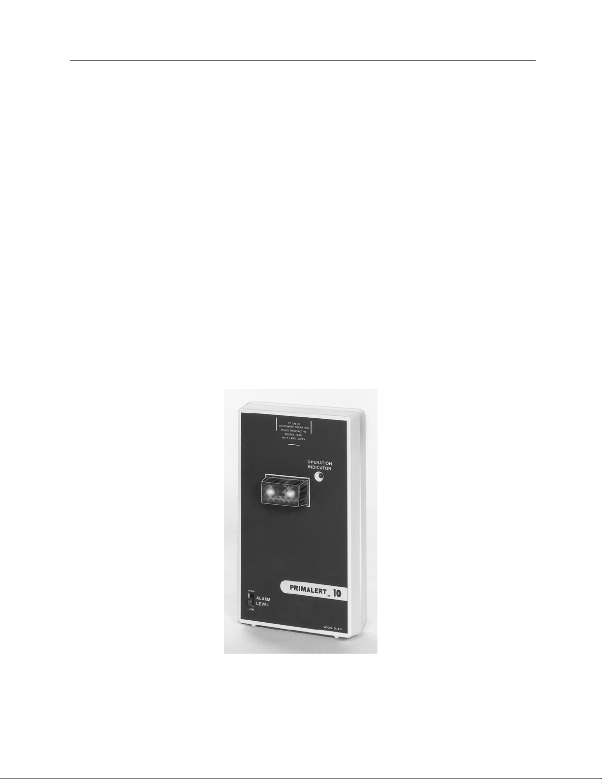
The Primalert 10 is a compact monitor providing a dependable, continuous means of monitoring radiation
levels and alerting personnel to hazardous conditions. If a therapy system malfunctions, it’s controls may
falsely indicate a safe condition even though the source/beam is on, posing a threat of excessive
radiation exposure to the therapist and technician.
The Primalert 10 monitor is activated when the radiation level exceeds a preset value. The alarm level
(2.5 mR/h or 20 mR/h) is selected by means of a slide switch on the front panel. A pair of bright red lamps
on the face of the instrument flash a warning and continue to flash until safe conditions are reestablished.
Since the system can be activated by scattered radiation, it may be mounted anywhere in the radiation
therapy room. A flashing green OPERATION INDICATOR light continuously monitors the background
radiation and provides visible proof that the instrument is functioning. In high radiation fields (over 100
R/h), the unit will not jam and will continue to alarm.
The Primalert 10 also has a jack for attaching an optional remote Primalarm™ (Model 05-434) at a
location up to 100 feet from the main unit. The Primalarm provides audible and visual warnings of an
alarm condition.
Figure 1-1 Primalert 10
1-1
Page 6

Nuclear Associates 05-433
Operators Manual
Page 7

Specifications
Specifications
Section 2
Specifications
2.1 Specifications
Detector Energy compensated GM tube
137
Energy Dependence -10%, +40% from 50 keV to 2 Me, as referenced to
Selectable Alarm Level 2.5 mR/h or 20 mR/h (See Section 5, Range Switch Modification)
Visual Alarm Two flashing red lamps. 18 (field of view)
Alarm Reset Automatic (when radiation level drops below preset value)
External Alarm Jack on bottom of case permits
Feature Attachment of external audible visual alarm (Primalarm) at remote location
from the main unit
Cs
2
Response Time for Alarm 2 to 3 seconds
Power Part 14-314 (United States, Canada)
Input 117 VAC, 60 Hz 12 W
Output 12 VDC, 500 mA
Part 14-400 (Europe)
Input 230 VAC 50 Hz
Output 12 VDC, 500 mA
Part 14-417 (United Kingdom)
Input 230 VAC 50 Hz
Output 12 VDC, 580 mA
Part 14-417, Part 14-416 (Australia)
Dimensions 6 in. x 3.5 in. x 1.5 in.
(H x W x D) 15.2 cm x 8.9 cm x 3.8 cm
Operating Conditions 10° C to 40° C (50° F to 104°F) Maximum of 90% relative humidity
(non-condensing)
Accessories Supplied Appropriate 115 V (230V) CE approved converter
Wall mounting bracket P/N 102007
Spare #74 lamp. P/N 680010
T-1¾ bulb, 14 V C 0.1 A, #74 Midget
Accessories Available Primalarm Remote Alarm Unit P/N 05-434
137
10 uCi,
Primapak™ P/N 05-441 Backup battery Pack
Cs license exempt check source P/N 62-103
2-1
Page 8

Nuclear Associates 05-433
Operators Manual
Page 9

Installation
Mounting
3
Section 3
Installation
3.1 Mounting
The mounting bracket supplied may be attached to any convenient vertical mounting surface. Before
mounting the bracket to the wall, however, make sure that the six-foot converter power cord will reach the
nearest power outlet.
The wall-mounting bracket comes supplied with double-sided foam tape already attached. Just peel off
the protective paper covering and firmly apply to the mounting surface.
Once in place, the bracket cannot be moved or
removed without destroying the tape. Make sure of
your installation site before applying. If you wish to
attach the bracket with screws, mounting holes are
also provided.
3.2 Power
The plug on the end of the converter power cord should first be inserted into the jack on the bottom of the
Primalert. The converter should then be plugged into the wall outlet.
3.3 Optional Power
The Primapak Backup battery pack (P/N 05-441) provideds a sourced of 12 to 16 VDC power.
The converter plug supplies this voltage.
The plug is a Switchcraft S760, or equivalent, with the sleeve negative and pin positive. The current
drain at background radiation levels is about 25 mA and about 250 mA at full alarm levels.
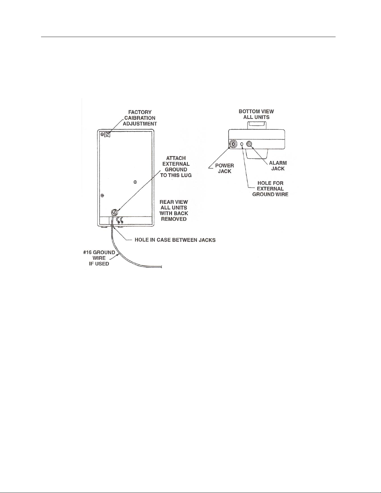
3.4 Grounding
If it is desired to ground the instrument with a separate ground wire, as may be required under certain
codes, Figure 3-1 shows how to accomplish this. Simply remove the back cover by loosening the single
screw in the center of the cover. Note the position of the ground terminal in Figure 3-1. Attach the wire by
running it up through the small hole between the jacks. At least a #16 gauge wire should be used for this
purpose.
3-1
Page 10
Nuclear Associates 05-433
Operators Manual
3.5 Routing Cleaning
Do not immerse the Model 05-433 Primalert 10. The unit is not waterproof. Liquid could damage the
circuits. The unit should be kept clean and free from dirt and contamination. The unit may be cleaned by
wiping with a damp cloth using any commercially available cleaning or decontaminating agent.
Figure 3-1 Instrument Grounding Diagram
3-2
Page 11

Operation
Setup
4
Section 4
Operation
4.1 Setup
Attach the power cord (converter) into the Primalert and plug converter unit into the wall receptacle as
noted in Section 3. The unit should alarm for 2 to 3 seconds before the automatic reset extinguishes the
indicators.
The unit should now be operational with the OPERATION INDICATOR flashing on or off with each
background pulse received.
4.2 Testing
Test the unit for proper operation by placing a check source (10 uCi,
front panel in the position indicated with the label down. The alarm should activate in the low (2.5 mR/h)
setting.
137
Cs, P/N 05103) on the top of the
4.3 Lamp Replacement
1. Remove the power cord plug.
2. Loosen screw in back of unit and remove back cover.
3. Remove the three Phillips head screws holding the board.
4. Pull out defective lamp. DO NOT TWIST.
5. Push in replacement lamp (type #74) and replace the printed circuit board and back cover.
4-1
Page 12

Nuclear Associates 05-433
Operators Manual
Page 13

Range Switch Modification
Range Switch Modification
Section 5
Range Switch Modification
5.1 Range Switch Modification
It is possible to modify the range of the Primalert to be other than the 2.5/20 mR/h, which is standard for
the range switch LOW and HIGH positions. The modification may be easily made by the customer to
provide any of the following two range positions: 2.5, 5, 10, 20 or 40 mR/h.
If it is desired to change the range on the Primalert 10, simply remove the back cover by removing the
center screw. The back of the printed circuit board will then be exposed showing clearly two jumpers
attached to the 2.5 and 20 mR/h solder points. The 2.5 mR/h jumper corresponds to the range switch
HIGH position. Simply unsolder the upper end of the jumper wire and insert it in the position(s) desired.
Be sure to observe the warning notice in regard to soldering.
5
5-1
Page 14

Nuclear Associates 05-433
Operators Manual
Page 15

Warning
Warning
6
Section 6
Warning
6.1 Warning
This instrument contains CMOS integrated circuits. No service should ever be attempted unless by a
competent technician thoroughly familiar with these devices. Static charges normally present in a dry
atmosphere or leakage current in soldering irons or other non-grounded tools can instantly destroy CMOS
integrated devices. If this device has I.C. sockets, do not even attempt to remove or replace them without
observing anti-static and leakage current precautions.
6-1
Page 16

Fluke Biomedical
Radiation Management Services
6045 Cochran Road
Cleveland, Ohio 44139
440.498.2564
www.flukebiomedical.com/rms
 Loading...