

Fluidmaster MONACO 1000A-002 Quick Install Manual

FULL
FLUSH
HALF
1
1
B
B
Full Float #
Half Float #
Full Window #
4.5/3L 6/3L 9/4.5L
CISTERN FLUSH VOLUME CONVERSION SETTINGS
9.5
12.5
1
5
12
1
1
9
1
A
B
C
CISTERN FLUSH VOLUME CONVERSION SETTINGS
Install with Confidence
1000A-002
MONACO™ UNIVERSAL CISTERN with LINK & SEAT
QUICK Install Guide
Cistern Plug (P re-Installed)
(FM4)
391mm
TOP DOWN VIEW
FULLHALF
Outlet Valve (Pre-Installed)
(FM3)
FULLHALF
(Blue) (Whi te)
Button (Pre-Installed)
(FM 1)
Inlet Valve (Pre-Installed)
(FM2)
420mm
133 mm
Link
(FM14)
Seat Bolt (x2)
(FM16)
Fixed Hole Screw (x2)
(FM6A)
Wall Fixing Bracket (FM5)
Bracket Screw (x2)
(FM6B)
PARTS OVERVIEWCISTERN TANK OVERVIEW
Seat Plate (x2)
(FM18)
Wall Anchor (x2)
(FM7)
Kee-Seal
(FM8)
Seat with Link Connection Plate (FM15 )
Seat Nut (x2)
(FM18)
Pan Entry Flush Pipe
Double Cone Washer
Flush Pipe Wedge Seal
(FM12)
(FM9)
277mm
Mid/High
Flush Pipe
(F M11)
90° Elbow
Flush Pipe
(FM10)
Flush Pipe
Coupling Nut
(FM13)
295mm
A: OPEN LID
335mm
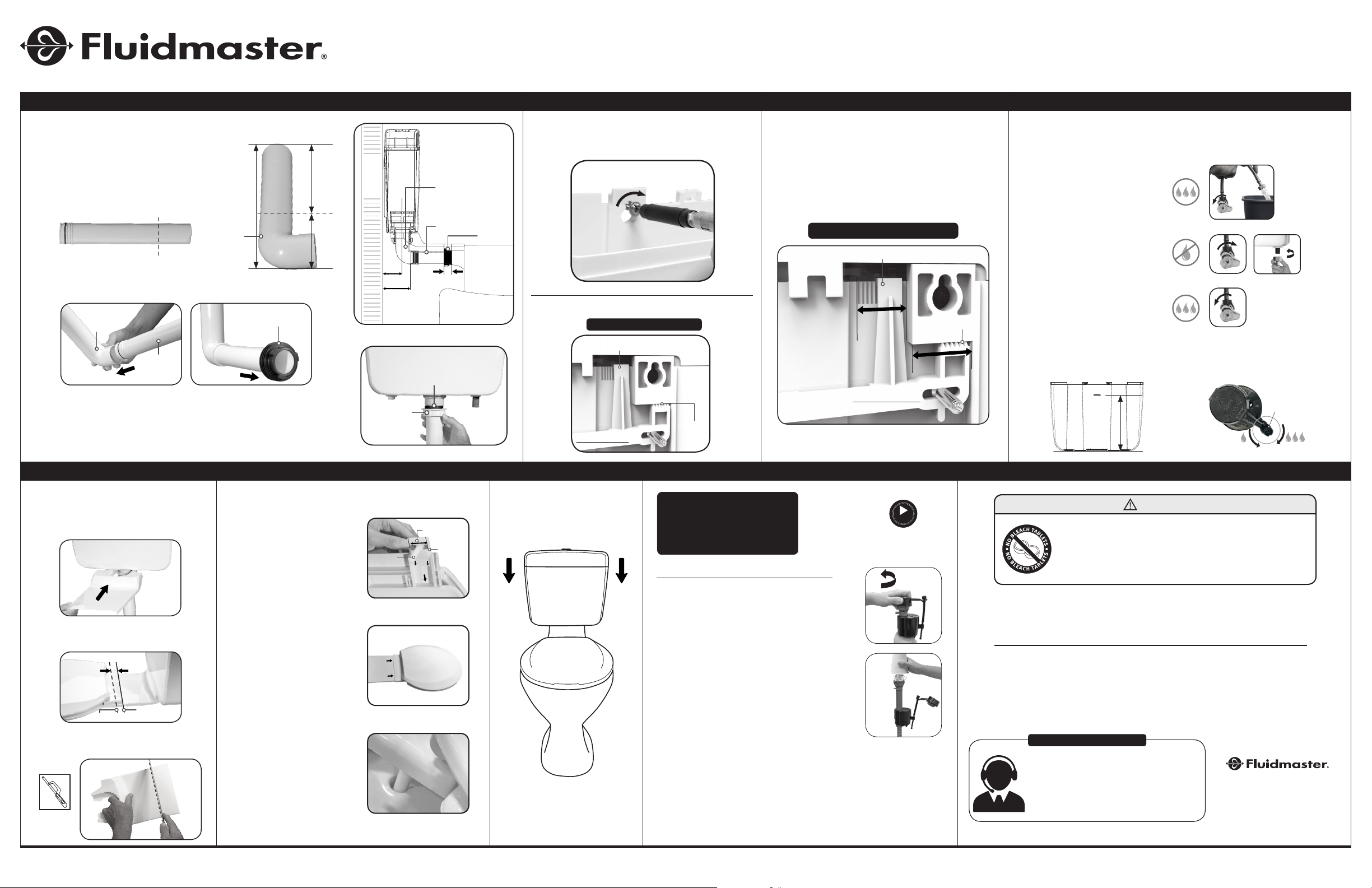
PRE-INSTALLATION
B: FLUSH VOLUME CONVERSION
* Fluidmaster Monaco Cistern pre-set flush volume settings = 4.5/3L system.
For pairing to a 4.5/3L pan, no flush volume set ting adjustment is required.
CONVERTING TO 6/3L OR 9/4.5 FLUSH VOLUME SYSTEM
B1: Remove black cistern tank spacer.
B2: Remove flush valve body & adjust
full and half float settings per Flush
Volume Conversion Table (below)
FLUSH
FULL
A
FLUSH
A
C
B3: Re-install flush valve body and
black cistern tank spacer. Ensure
proper full and half flush alignment.
16
13
NOTE: ( Blue) = Half Flush
(White) = Full Flush
C
3
2
1
Full Float #
A
Half Float #
B
C
Full Window #
4.5/3L 6/3L 9/4.5L
1
9.5
12.5
5
12
1
9
1
1
CHOOSE DESIRED INSTALL METHOD:
(C1)
Flush-Low Level
with Link.
Recommended: Recommended: Recommended:
Low-Mid Level
(Uncut Height)
(C2)
(C3)
Mid-High Level
(Uncut Height)
OR
STEP 1: MARK WALL FOR SCREW HOLES (SEE INCLUDED TEMPLATE)
FIXED HOLE
232mm
116mm
up to
869m m *
(C3)
up to
574mm *
(C2)
356mm
(C1)
FIXED HOLE
For lower height, cut
*
flush pipes accordingly.
FIXING BRACKET
FIXING BRACKET
223mm
up to
815m m *
111 . 5mm
(C3)
*
up to
520mm *
(C2)
For lower height, cut
flush pipes accordingly.
302mm
(C1)
WALL
WALL
TOP OF PAN
TOP OF PAN
STEP 2: SET SCREWS PER INSTALL METHOD
With Wall Anchor
Without Wall Anchor
With Wall Anchor
Without Wall Anchor
8mm
3mm
8mm
3mm
Wall Anchor (FM7)
Bracket Screw
(FM6B)
Wall Fixing Bracket (FM5)
Bracket Screw
(FM6B)
www.Fluidmaster.com.au
15mm
Fixed Hole
Screw
(FM6A)
Wall Anchor (FM7)
WALL
Install with Confidence
1000A-002 QUICK Install Guide
MONACO™ UNIVERSAL CISTERN with LINK & SEAT
INSTALLATION
STEP 3: INSTALL FLUSH PIPES
A: Trim / Cut Flush Pipes as needed
per install type.
Note: C1 Install type (with link) shown. For install
types C2 or C3, no cutting required on 90° elbow
(FM 10) or Mid/High ( FM 11) Flush Pipes.
90° Elbow
Pan Entry Flush Pipe
(FM9)
B: Lubricate kee-seal with soap and water.
Insert flush pipes and connect to pan.
90° Elbow
Flush Pipe
(FM 10)
C: Fit Flush pipe coupling nut and double cone washer wedge seal onto
flush pipe. Hand-tighten Flush pipe coupling nut and secure flush
pipe to outlet valve shank.
DO NOT OVERTIGTHEN
Cut this
side only
Pan Entry
Flush Pipe
(FM9)
Flush Pipe
(FM 10)
Cut this
side only
335mm
Kee-Seal
215 mm120 mm
(FM8)
Cut length
After cut
68mm
99mm
Double Cone Washer
Flush Pipe Wedge Seal
Flush Pipe
Coupling Nut
(FM13)
90° Elbow
Flush Pipe
Pan Entry
Flush Pipe
(FM12)
(FM 10)
(FM9)
27mm
Kee-Seal
(FM8)
STEP 4: HANG CISTERN TANK
FIXED HOLE
FIXING BRACKET
BACK OF CI STER N TANK
Connection Point
Connection
AGAINST WALL
Point
STEP 5: CISTERN ALIGNMENT
(ONLY APPLICABLE FOR FIXING BRACKET INSTALL METHOD)
A: Slightly move cistern tank left to right as
needed on wall fixing bracket to ensure proper
cistern tank and flush pipe alignment with pan.
BACK OF CISTERN TANK
Connection Point
11mm
AGAINST WALL
Connection Point
11mm
STEP 6: WATER SUPPLY CONNECTION
& FINE-TUNE TANK WATER LEVEL
A: Turn on water & flush
water supply line.
B: Turn off water & connect
water supply line to cistern
with approved fittings.
Hand-tighten only.
DO NOT OVERTIGHTEN.
C: Turn on water & check
for leaks.
D. FLUSH THE CISTERN TO CHECK THE TANK WATER LEVEL
After the water stops filling the tank, the water level should be at
water line “WL” mark (255mm) to ensure a proper flush.
WL
255mm
–
RIGHT
Tank Water Lev el
Adjustment Screw
+
STEP 7: ATTACH LINK
(IF REQUIRED)
A: Secure link into position.
B: Set seat onto link to mark desired
seat end point & cut point.
23mm
Cut Point
C: If cut required, cutting line guides
reference on back of link as needed.
Mini Hack Saw
Seat End
Point
INSTALLATION
STEP 8: INSTALL SEAT
A: Inser t Seat Bolt Plates
in Connection plate
(follow arrow guides).
Seat Bolt
(FM16 )
For Link Application
Insert link to seat
connection plate. Set
seat bolts into pan
holes and hand-tighten
seat bolt nuts.
For Non-Link Application
Set seat bolts into
pan holes and handtighten seat bolt nuts.
20mm
Seat Plate
(FM18)
STEP 9: AT TACH /
RE-SECURE LID
TROUBLESHOOTING
IF THE INLET VALVE:
• DOES NOT TURN ON
• WON’T TURN OFF
See Our Troubleshooting
• WON’T REFILL TANK
REMOVE CAP AND CHECK FOR DEBRIS
A: Turn off water supply.
B: Flush cistern.
C: With right hand push float up, grip and hold
shaft under float.
D: With left hand twist cap and lever arm coun-
terclockwise to unlock cap. Let cap hang on
float cup.
E: Hold empty cup upside down over un-
capped valve to prevent splashing.
F: Turn water supply on and off a few times.
G: Turn water supply off.
H: Replace valve cap.
• Place cap assembly on top of gray valve body
by aligning cap arm and adjustment rod.
• Press down on top cap while rotating top & arm
clockwise to locked position.
* Always use genuine Fluidmaster parts when installing or repairing. Fluidmaster will not be
responsible or liable for use of non-Fluidmaster parts during installation or repair.
VIDEO
HOW-TO VIDEO
http://bit.ly/2yAdZn7
TURN
COUNTER-
CLOCKWISE
WARNING
DO NOT US E IN-C ISTERN DRO P-IN TOILE T BOWL C LEANERS C ONTAI NING B LEA CH OR
CHLORINE. Use of suc h products will : (1) RESU LT IN DAMAGE to Cistern components and
MAY CAU SE FLOODING a nd PROP ERT Y DAM AGE and (2) VOID F LUID MASTER WAR RANTY.
DO NOT ove rtigh ten nut s or cist ern/ bowl may cr ack. A lways use q ualit y Fluidmaster
part s when ins tallin g or repai ring. Fl uidmas ter will not be resp onsibl e or liable for use of
non-Fluidmaster parts during installation or repair.
WARRANTY
Our goods come wi th guarantees t hat cannot be exclu ded under the Aus tralian Consumer Law. You ar e entit led
to a repla cement o r refund for a majo r failure and for co mpensa tion fo r any othe r reasonably fo reseea ble loss o r
damage. You are also e ntitle d to have th e goods repaire d or replaced if the g oods fa il to be of ac cepta ble quali ty
and the f ailure does not amount to a major failure.
To present c laims under this wa rrant y, please conta ct your pl ace of pur chase o r conta ct Fluid master Austr alia
Holdings Pty Ltd. NOTE: Original proof of purchase required.
Warranty excludes incorrect installation . Installatio n shall be i n accordance with AS/ NZS 35 00.1 and AS/NZ S
3500.2 (Install with licensed plumber; any installation processed without licensed plumber will void warranty)
10 Year Part s Replacement / 1 Year Part s & Labor Warran ty.
Only cle an with soap and warm water to mainta in quali ty finis h. Do not use harsh c hemica l cleaners.
ADDITIONAL QUESTIONS?
For installation assistance, contact our
technical services department.
EMAIL, or CALL our toll-free number.
Phone: +61 (03) 8870 2555 | Toll Free: 1 800 931 166
IN NEW Z EALAN D Call 09 415 5585
Email: salesau@fluidmaster.com
Website: www.Fluidmaster.com.au
Fluidmaster Au stralia Holdings Pty Ltd
5B/100 New Street
Ringwood, Victoria 3134
Australia
20-0006-1 Grev. 2, 10/19 (S heet 1)
www.Fluidmaster.com.au
 Loading...