

Page 1
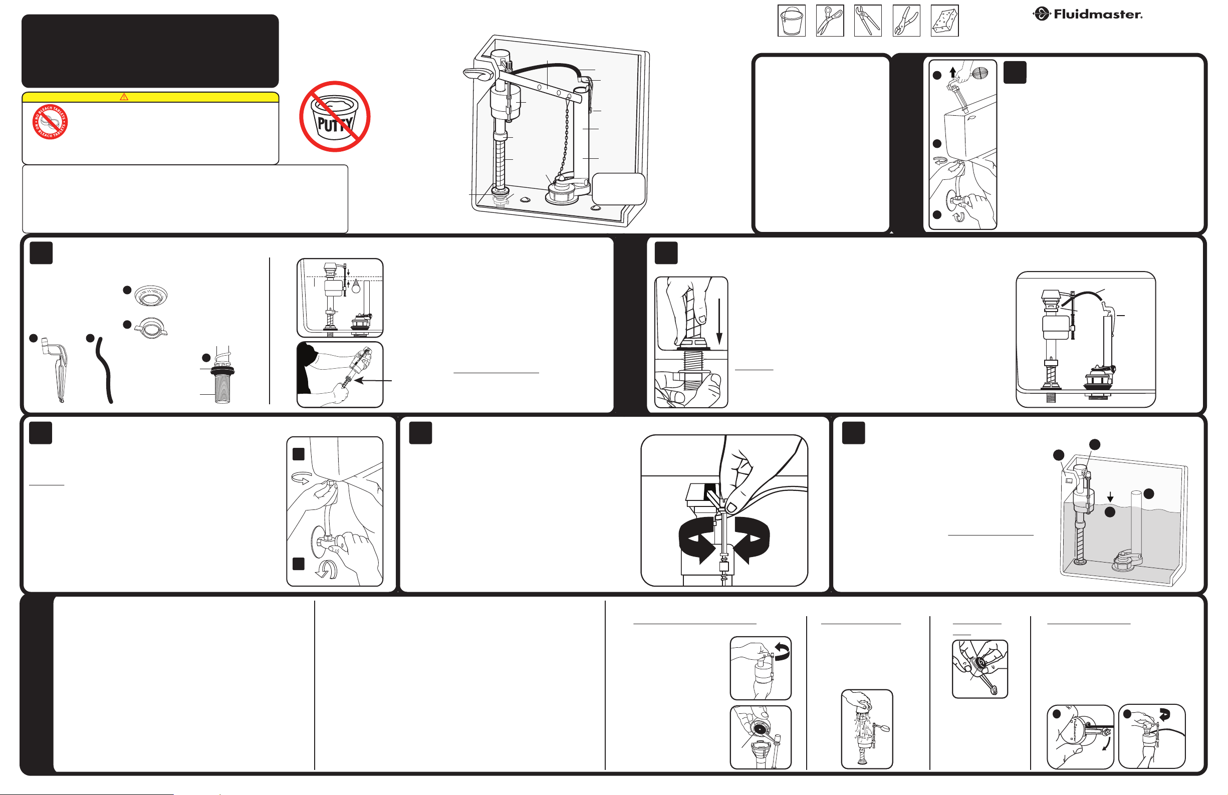
242
SEAL
B
A
REFILL
CLIP
REFILL TUBE
NIPPLE
“C .L”
MARK
MEASURE
HEIGHT ONLY:
DO NOT INS TALL
LOCK
RING
A
B
C
PART# 4 -743, Grev. 6, 08/14
FLUIDMASTER
®
400A FILL VALVE
INSTALLATION INSTRUCTIONS
WARNING
DO NOT USE IN-TANK DROP-IN TOILET BOWL CLEANERS CONTAINING BLEACH OR
CHLORINE. Use of such products will: (1) RESULT IN DAMAGE to tank components and MAY
CAUSE FLOODING and PROPERTY DAMAGE and (2) VOID FLUIDMASTER WARRANTY.
Fluidmaster Flush 'n Sparkle Toilet Bowl Cleaning System is recommended for those
because it will not damage the components. DO NOT overtighten nuts or tank/bowl may crack. Always use quality
Fluidmaster parts when installing or repairing. Fluidmaster will not be responsible or liable for use of non-Fluidmaster parts
during installation or repair.
Subject to the “Exclusions” set forth below, Fluidmaster Inc. promises to the consumer to repair, or at the option of Fluidmaster Inc. to replace any
part of this plumbing product which proves to be defective in workmanship or materials under normal use for five years from the date of purchase. All
costs of removal, transportation and reinstallation to obtain warranty service shall be paid by the consumer. During this “Limited Five Year Express
Warranty,” Fluidmaster Inc. will provide, subject to the “Exclusions” section set forth below, all replacement parts free of charge, necessary to correct
such defects. This “Limited Five Year Warranty” is null and void if this plumbing product has not been installed and maintained in accordance with all
EXCLUSIONS: FLUIDMASTER INC. SHALL NOT BE LIABLE FOR INCIDENTAL OR CONSEQUENTIAL DAMAGES, INCLUDING COSTS OF INSTALLATION, WATER
DAMAGE, PERSONAL INJURY OR FOR ANY DAMAGES RESULTING FROM ABUSE OR MISUSE OF THE PRODUCT, FROM OVERTIGHTENING OR FROM FAILURE
TO INSTALL OR MAINTAIN THIS PLUMBING PRODUCT IN ACCORDANCE WITH THE WRITTEN INSTRUCTIONS, INCLUDING USE OF NON-FLUIDMASTER PARTS.
DO NOT USE IN-TANK DROP-IN TOILET BOWL CLEANERS CONTAINING BLEACH OR CHLORINE. USE OF SUCH PRODUCTS WILL RESULT IN DAMAGE TO TANK
choosing to use in-tank bowl cleaners and WILL NOT VOID the FLUIDMASTER WARRANTY
LIMITED FIVE-YEAR EXPRESS WARRANTY
written instructions accompanying the product, and if non-Fluidmaster Inc. parts are used in installation.
COMPONENTS AND MAY CAUSE FLOODING AND PROPERTY DAMAGE. USE OF SUCH PRODUCTS WILL VOID THIS WARRANTY.
DO NOT USE
SHANK
WASHER
FLOAT
CUP
LOCK RING
FILL
VALVE
LOCKNUT
TANK LEVER
FLAPPER
REFILL TUBE
REFILL CLIP
METAL TAB
OVERFLOW
PIPE
FLUSH
VALVE
TANK SHOULD
LOOK LIK E THIS
WHEN SET UP IS
COMPLETE
TOOLS
NEEDED
ScissorsBucket
PARTS
IN THIS KIT:
(1) Fill Valve
(1) Shank Washer
(1) Locknut
(1) Refill Tube
(1) Refill Clip
Large Adjustable
Pliers
Pliers
PREPARATION
30800 Rancho Viejo Road, San Juan Capistrano, CA 92675
SpongeAdjustable
Contact Fluidmaster for troubleshooting help or visit www.fluidmaster.com
www.Fluidmaster.com • 800-631-2011
M-F 5:30 am - 5:00 pm PST.
Remove Old Fill Valve
1
tank. Then follow steps A-C.
A. Turn off water supply (Clockwise). Flush toilet and remove
excess water from tank with sponge.
B. Remove water supply line coupling nut. Remove locknut
from under tank.
C. Remove fill valve from tank.
Remove tank lid. Use pencil to mark water level of
Preparing the Fill Valve for Installation
2
Fill Valve Assembly Parts
A) Refill Clip
B) Refill Tube
C) Shank Washer
D) Locknut
E) Threaded Shank
A
B
C
D
Threaded
Attach Water Supply Connector
4
years old to prevent flooding and property damage.
A. Attach water supply coupling nut to fill valve. Turn coupling nut
clockwise by hand until tight.
WARNING: Do not over tighten the nut as it could damage fill valve or
coupling nut, resulting in flooding and property damage. Fluidmaster Click
Seal
tightening.
B. Turn on water supply and check for leaks. If you find leaking at bottom of
tank, turn nut just enough to stop leaking. Then flush toilet to check.
Inspect water supply connector. Replace if it is worn or over 5
®
connector is recommended: A perfect seal every time without over
Shank
Washer
Shank
Place shank
washer onto
threaded
shank of fill
valve. Flat
side up.
E
Installing New Fill Valve
Position fill valve in tank, but do not fully install yet. Top
of fill valve MUST be set 3” above overflow pipe. This will
automatically place CRITICAL LEVEL MARK / C.L. Mark,
”
1
1” above the top of overflow pipe. Remove fill valve from
tank to adjust height.
Adjust height of fill valve by holding lower shank with right
hand and top of valve with left hand. Twist the lower shank
counter clockwise to increase valve height and clockwise
to decrease valve height. You should hear several “clicks”.
Place valve in tank and check height again. THE CRITICAL
LEVEL MARK, identified by C.L. on valve, MUST be
positioned 1” above top of overflow pipe. This is a
requirement of the Universal Plumbing Code.
Do not move lock ring. It holds the valve body and shank
together under pressure. Do not interchange body with old
shank as leaking can occur.
Adjusting Tank Water Level
5
turning water level adjustment screw. When adjusting float cup,
flush tank first. Then make adjustment while tank is filling.
To adjust tank water, turn adjustment screw clockwise to raise
water level or counter clockwise to lower water level. Once
adjusted, flush toilet and check new level. Repeat if necessary.
HINT: When you twist adjustment screw 8 times - float moves 1/2”.
With water turned on, set float cup to desired level, by
3
valve. Align fill valve nipple to face center of tank. Press down on shank from inside
INSTALLATION
Place fill valve in tank. Make sure lid will sit on top of tank without touching
tank while tightening locknut.
Hand-tighten only. DO NOT OVER TIGHTEN. Over tightening
may crack the fill valve or tank causing flooding. Make sure the
float cup does not touch the tank walls or tank lever and flush
valve.
Attach one end of refill tube to refill clip. Place clip on right
side of overflow pipe. Attach other end of tube to nipple on fill
valve with a slight arch (See drawing to the right). Cut tube as
necessary.
WARNING: Do not shove refill tube down overflow pipe. This
may cause significant water waste.
Code Compliance
6
water level of tank are correctly set.
1. THE TOP OF OVERFLOW PIPE (A) must be minimum of 1"
below TANK LEVER HOLE (B).
2. WATER LEVEL (C) is set below top of Overflow Pipe
(Fluidmaster recommends 1/2”).
3. THE CRITICAL LEVEL MARK / C.L. Mark (D) identified by
C.L. on fill valve must be positioned 1” above top of overflow
pipe. This is a requirement of the Universal Plumbing Code.
Code Compliance helps protect your home & drinking water
supply.
Once fill valve is installed, ensure overflow pipe and
Correct set up of refill tube and refill clip to overflow pipe
D
B
WATER
FILL
VALVE
LEVEL
C
A
OVERFLOW
PIPE
IF FILL VALVE DOES NOT TURN ON, WILL NOT
TURN OFF, OR WILL NOT REFILL THE TANK
– Please keep a copy of these instructions on the property in which the product was installed.
AFTER THE FLUSH
• Remove top cap and check for debris. If you find debris, or flow
is weak: Inspect lower section of fill valve for partial blockage.
Partial blockage may be at shut off valve or in water supply line
(See “REMOVING THE VALVE CAP ASSEMBLY & FLUSHING OUT
DEBRIS”).
• If fill valve has been in use for some time and/or float cup does not
TROUBLESHOOTING
drop when flushing tank, replace seal with a genuine Fluidmaster 242
seal (See “IF REPLACING SEAL”).
IF FILL VALVE TURNS ON AND OFF BY ITSELF
• This indicates the tank is losing water. The fill valve is refilling lost water.
Clean flapper and drain seat. If leak continues, change flapper or flush
valve. Install Fluidmaster 502, 507AKR, 540AKR or 555C kit.
IF WATER LEVEL IN BOWL IS TOO LOW
• Make sure the refill tube is supplying water down overflow pipe.
• Water level in tank may be too low. Raise water level to 1/2” below top of
overflow pipe (See “ADJUSTING TANK WATER LEVEL”). You may have
to lengthen the fill valve in order to increase the water level in tank (See
“PREPARING THE FILL VALVE FOR INSTALLATION”).
• Flapper may be closing too soon. Give flapper chain approximately 1/2”
of slack.
Removing Valve Cap Assembly, Flushing Out Debris, Replacing Seal, & Replacing Valve Cap Assembly
Removing Valve Cap Assembly
Turn off water supply
& flush out tank. Push
float up with right hand
(see picture). Grip and
hold shaft under float
with right hand. With left
hand, twist cap and lever
counter clockwise 1/8th
of a turn to unlock the top
cap. Pressing down on top
may be helpful with older
valves. Let cap assembly
hang on float cup.
Flushing Out Debris
Hold cup upside down over
uncapped valve to prevent
splashing. Turn water supply
on and off a few times.
Turn water supply off when
putting cap back on valve.
If Replacing
Seal
SEAL
LOCATION
If Replacing Seal:
Use only a genuine
Fluidmaster 242 seal.
Replacing Valve Cap
A. Place cap assembly on top of gray valve
body by aligning cap arm and adjustment
rod next to refill tube.
B. Press down on top cap while rotating
top & arm clockwise to locked position.
A
B
Page 2

PART E# 4-743, Grev. 6, 08/14
B
A
SUJETADOR DE
RECARGA
TUBO DE
RECARGA
MANGUITO
ROSCADO
A
B
C
MARCA
“C.L.”
MIDA SOLO LA A LTURA:
NO INSTALE
ANILLO DE
SEGURIDAD
SELLO
242
INSTRUCCIONES DE INSTALACIÓN
PARA LA VÁLVULA DE LLENADO
®
FLUIDMASTER
400A
ADVERTENCIA
O
C
N
S
NO USE LIMP IADORES DE TAZA DE I NODORO QUE SE COLO QUEN EN EL TANQUE QUE C ONTENGAN
A
C
T
L
E
O
L
R
B
A
T
T
A
B
L
E
T
NO apriete demasiado las tuercas ya que el tanque y/o la taza se pueden agrietar. Siempre use piezas de calidad Fluidmaster al
instalar o reparar. Fluidmaster no será responsable por el uso de repuestos que no sean de Fluidmaster durante la instalación o el
mantenimiento.
Sujeta a las "Exclusiones" establecidas a continuación, Fluidmaster Inc. le garantiza al consumidor reparar o, a elección de Fluidmaster Inc., sustituir cualquier pieza de este producto de
plomería que presente pruebas de defectos en sus materiales o mano de obra, bajo un uso normal, por cinco años desde la fecha de compra. Todos los gastos por extracción, transporte
o reinstalación de la unidad para obtener el servicio de la garantía deberán ser abonados por el consumidor. Durante esta "Garantía expresa limitada por cinco años", Fluidmaster Inc.
proporcionará en forma gratuita, sujeto a la sección de "Exclusiones" presentada a continuación, todos los repuestos necesarios para corregir tales defectos. La presente "Garantía limitada
por cinco años" será nula si no se ha instalado y mantenido el producto de plomería de conformidad con las instrucciones por escrito que acompañan al producto, y si se utilizaron piezas
EXCLUSIONES: FLUIDMASTER INC. NO SERÁ RESPONSABLE POR LOS DAÑOS INCIDENTALES O INDIRECTOS, INCLUYENDO LOS GASTOS DE INSTALACIÓN, LOS DAÑOS CAUSADOS POR EL AGUA,
LAS LESIONES FÍSICAS O CUALQUIER OTRO DAÑO, QUE RESULTAREN POR EL USO EXTREMO O INCORRECTO DEL PRODUCTO, APRETARLO DEMASIADO O POR NO INSTALAR O MANTENER ESTE
PRODUCTO DE PLOMERÍA CONFORME A LAS INSTRUCCIONES POR ESCRITO, INCLUYENDO EL USO DE PIEZAS QUE NO SEAN DE FLUIDMASTER. NO UTILICE LIMPIADORES QUE SE COLOQUEN EN
EL TANQUE QUE CONTENGAN CLORO. EL USO DE TALES PRODUCTOS GENERARÁ DAÑOS EN LOS COMPONENTES DEL TANQUE Y PODRÍA CAUSAR INUNDACIONES Y DAÑOS MATERIALES. EL USO
BLANQUEADOR O CLORO. El uso de tale s product os: (1) GENER ARÁ DAÑOS en los componentes del tanque
O
y PODRÍA CAUSAR INUNDACIONES y DAÑOS MATERIALES, y (2) ANULARÁ LA GARANTÍA DE
O
FLUIDMASTER. Se recomienda el uso del sistema de limpieza de taza de inodoros Flush 'n Sparkle de
R
O
L
C
A
Fluidmaster para quienes prefieran utilizar limpiadores de taza dentro del tanque y NO ANULARÁ LA
S
N
O
C
GARANTÍA DE FLUIDMASTER porque no dañará los componentes.
GARANTÍA EXPRESA LIMITADA POR CINCO AÑOS
que no sean de Fluidmaster Inc. en la instalación.
DE TALES PRODUCTOS INVALIDARÁ ESTA GARANTÍA.
NO UTILICE
ARANDELA
DEL VÁS TAGO
PALANCA DEL TANQUE
SUJETA DOR
DEL FLOTADOR
ANILLO DE SEGURIDAD
VÁLVULA
DE LLENADO
TAPÓN
CONTRATUERCA
TUBO DE
RECARGA
SUJETA DOR
DE REC ARGA
LENGÜ ETA DE
METAL
TUBER ÍA DE
DESBORDE
VÁLVULA PARA
DESCARGA DE
INODORO
EL TANQUE
DEBE VERSE ASÍ
CUANDO H AYA
TER MINADO LA
INSTALACIÓN
HERRAMIENTAS
NECESARIAS
Pinz as grandes
TijerasCubeta
y regulables
ESTE KIT
INCLUYE:
(1) Válvula de llenado
(1) Arandela del vástago
(1) Contratuerca
(1) Tubo de recarga
(1) Sujetador de recarga
ajustables
PREPARACIÓN
30800 Rancho Viejo Road, San Juan Capistrano, CA 92675
EsponjaPinzas
Comuníquese con Fluidmaster para obtener ayuda para resolver problemas o visite www.fluidmaster.com
www.Fluidmaster.com • 800-631-2011
De lunes a viernes de 5:30 a.m. a 5:00 p.m. hora estándar del Pacífico.
Quite la Válvula de Llenado Vieja
1
el nivel del agua del tanque. Luego, siga los pasos A-C.
A. Cierre el suministro de agua (en dirección de las manecillas
del reloj). Descargue el inodoro y seque el exceso de agua del
tanque con una esponja.
B. Desenrosque la tuerca de acople delconector de suministro
de agua. Desenrosque la contratuerca de la parte inferior del
tanque.
C. Saque la válvula de llenado del tanque.
Quite la tapa del tanque. Utilice un lápiz para marcar
Preparación de la Válvula de Llenado Para la Instalación
2
Piezas de ensamblaje de la válvula de
llenado
A) Sujetador de recarga
B) Tubo de recarga
C) Arandela del vástago
D) Contratuerca
E) Vástago roscado
A
B
C
D
Arandela
del vástago
Vástago
roscado
No Mueva el Anillo de Seguridad
4
bajo presión. No intercambie el cuerpo con un vástago viejo ya que puede
provocar fugas.
A. Sujete la tuerca de acople del suministro de agua a la válvula de llenado.
Enrosque la tuerca de acople en dirección de las manecillas del reloj a mano
hasta que quede apretada.
ADVERTENCIA: No apriete demasiado la tuerca ya que puede dañar la
válvula de llenado o la tuerca de acople, causando inundaciones y daños a
la propiedad. Se recomienda el conector Fluidmaster Click Seal
da un sellado perfecto sin apretar demasiado.
B. Abra el suministro de agua y revise que no haya fugas. Si encuentra una
fuga en la parte inferior del tanque, apriete la tuerca solo lo suficiente como
para detener la fuga. Luego, descargue el inodoro y vuelva a revisar.
El anillo mantiene juntos el cuerpo de la válvula y el vástago
Coloque la
arandela del
vástago sobre el
vástago roscado
de la válvula
de llenado. El
lado plano debe
quedar hacia
arriba.
E
®
: Siempre
Instalación de La Nueva Válvula de Llenado
INSTALACIÓN
3
Coloque la válvula de llenado en el tanque. Asegúrese de que la tapa se asiente
en la parte superior del tanque sin tocar la válvula. Alinee el manguito roscado
de la válvula de llenado de manera que quede frente al centro
del tanque. Presione el vástago hacia abajo desde el interior del
tanque, a la vez que aprieta la contratuerca.
Apriete solo con las manos. NO APRIETE DEMASIADO. De
lo contrario, podría agrietar la válvula de llenado o el tanque o
producir una inundación. Asegúrese de que la taza flotante no
toque las paredes del tanque, la palanca del tanque ni la válvula de
descarga.
Conecte un extremo del tubo de recarga al sujetador de recarga.
Coloque el sujetador al costado derecho del tubo de desborde.
Conecte el otro extremo del tubo al manguito roscado de la
válvula de llenado arqueando la manguera un poco (consulte el
dibujo de la derecha). Corte el tubo si es necesario.
ADVERTENCIA: No empuje el tubo de recarga bajo el tubo de
desborde. Esto podría provocar un importante desperdicio de
agua.
Cumplimiento Con el Código
6
Una vez instalada la válvula de llenado, asegúrese de que
colocados de manera correcta.
1. LA PARTE SUPERIOR DE LA TUBERÍA DE DESBORDE (A) debe
estar a 2,54 cm como mínimo por debajo DEL ORIFICIO DE L A
PALANCA DEL TANQUE (B).
2. EL NIVEL DE AGUA (C) debe estar por debajo de la tubería de
desborde (Fluidmaster recomienda 1,27 cm).
3. LA MARCA DE NIVEL CRÍTICO / C.L. La marca (D) identificada
como C.L. en la válvula de llenado, debe estar a un mínimo de 2,54
cm por sobre la parte superior de la tubería de desborde. Este es un
requisito del código de plomería universal.
El cumplimiento con los códigos le permite proteger su hogar y el
suministro de agua potable.
la tubería de desborde y el nivel de agua del tanque están
Coloque la válvula de llenado en el tanque, pero todavía no la instale.
La par te superior de la válvula de llenado debe estar a 7,62 cm por
sobre la tubería de desborde. Esto ubicará automáticamente la
MARCA DE NIVEL CRÍTICO (C.L.). Marque 2,54 cm por sobre la parte
”
1
superior de la tubería de desborde. Retire la válvula de llenado del
tanque para ajustar la altura.
Ajuste la altura de la válvula de llenado, para ello sostenga el vástago
inferior con la mano derecha y la parte superior de la válvula con
la otra mano. Gire el vástago inferior en dirección contraria a las
manecillas del reloj para aumentar la altura de la válvula, o en sentido
contrario para disminuir la altura de la válvula. Escuchará varios
"clics". Coloque la válvula en el t anque y vuelva a revisar la altura. LA
MARCA DE NIVEL CRÍTICO, identificada como “CL” en la válvula,
DEBE estar a 2,54 cm por sobre la par te superior de la tubería de
desborde. Este es un requisito del código de plomería universal.
NO MUEVA EL ANILLO DE SEGURIDAD.
El anillo mantiene juntos el cuerpo de la válvula y el vástago bajo
presión. No intercambie el cuerpo con un vástago viejo ya que puede
provocar fugas.
Ajuste del Nivel de Agua del Tanque
5
el nivel deseado, girando el tornillo de ajuste del nivel de agua.
Descargue el tanque primero al ajustar la taza flotante. Luego haga
los ajustes mientras se llena el tanque.
Para ajustar el agua del tanque, gire el tornillo de ajuste en
dirección de las manecillas del reloj para subir el nivel del agua, o
en dirección contraria para bajar el nivel del agua. Una vez ajustado,
descargue el inodoro y verifique el nuevo nivel. Repita este
procedimiento si es necesario.
CONSEJO: Cuando gira el tornillo de ajuste 8 veces, el flotador se
mueve 1,27 cm.
Con el paso de agua abierto, coloque la taza flotante hasta
Corrija el ajuste del tubo de recarga y del
sujetador de recarga en la tubería de desborde
D
B
NIVEL
DE AGUA
A
C
VÁLVULA
DE LLENADO
TUBERÍA DE
DESBORDE
SI LA VÁLVULA DE LLENADO NO SE ABRE, NO SE
CIERRA O NO LLENA EL TANQUE DESPUÉS DE LA
DESCARGA
– Guarde una copia de estas instrucciones en donde instale el producto.
• Retire la tapa superior y revise si hay desechos. Si encuentra desechos
o si hay poco flujo: Inspeccione la sección inferior de la válvula de
llenado en busca de una obstrucción parcial. La obstrucción parcial
podría estar en la válvula de cierre o en la tubería de suministro
de agua (Consulte “RETIRO DEL ENSAMBLE DE LA TAPA DE LA
VÁLVULA y ELIMINACIÓN DE DESECHOS”).
• Si la válvula de llenado ha estado en uso por un tiempo y/o la taza
flotante no baja cuando se descarga el tanque, reemplace el sello con
el sello 242 original de Fluidmaster (Consulte “SI VA A REEMPLAZAR
EL SELLO”).
SOLUCIÓN DE PROBLEMAS
SI LA VÁLVULA DE LLENADO SE ABRE Y SE CIERRA
POR SÍ SOLA
• Esto indica que el tanque esta perdiendo agua. La válvula de llenado está
recargando el agua perdida. Limpie el tapón y el asiento de descarga. Si
la fuga continúa, cambie el tapón o la válvula de descarga. Instale el kit
502, 507AKR, 540AKR o 555C de Fluidmaster.
SI EL NIVEL DE AGUA EN LA TAZA ES DEMASIADO BAJO
• Asegúrese de que el tubo de recarga suministre agua a través de la tubería
de desborde.
• Puede que el nivel de agua en el tanque esté demasiado bajo. Aumente
el nivel de agua del tanque a 1,27 cm por debajo de la parte superior de
la tubería de desborde (Consulte “AJUSTE DEL NIVEL DE AGUA DEL
TANQUE”). Podría necesitar alargar la válvula de llenado con el fin de
aumentar el nivel de agua del tanque (Consulte “PREPARACIÓN DE LA
VÁLVULA DE LLENADO PARA LA INSTALACIÓN”).
• Puede que el tapón se cierre demasiado pronto. De 1,27 cm más de
holgura a la cadena del tapón.
Retiro del ensamble de la tapa de la válvula, limpieza de desechos, reemplazo del sello y reemplazo del ensamble de la tapa de la válvula
Retiro del ensamble de la tapa de la válvula
Corte el suministro de agua y
descargue el tanque. Empuje el
flotador hacia arriba con la mano
derecha (consulte la imagen).
Agarre y sostenga el vástago bajo
el flotador con la mano derecha.
Con la mano izquierda, gire la tapa
y la palanca en dirección contraria
a las manecillas del reloj 1/8 de
giro para desbloquear la tapa
superior. El presionar hacia abajo la
parte superior puede ayudar con
las válvulas más antiguas. Deje el
ensamble de la tapa colgando de la
taza flotante.
Limpieza de desechos
Sostenga una taza boca abajo sobre
la válvula destapada para que no
salpique agua. Abra y cierre el
suministro de agua unas cuantas
veces. Vuelva a abrir el suministro
de agua al volver a poner la tapa en
la válvula.
Si va a reemplazar
el sello
UBICACIÓN
DEL SELLO
Si va a reemplazar
el sello: Use solo un
sello 242 original de
Fluidmaster.
Reemplazo de la tapa de la válvula
A. Coloque el ensamble de la tapa sobre el cuerpo de
la válvula gris, alineando el brazo de la tapa y la varilla
de ajuste junto al tubo de recarga.
B. Presione hacia abajo la tapa superior mientras
gira la parte superior y el brazo en dirección de las
manecillas del reloj hasta la posición de bloqueo.
A
B
 Loading...