

Fluidmaster 540 AKR User Manual
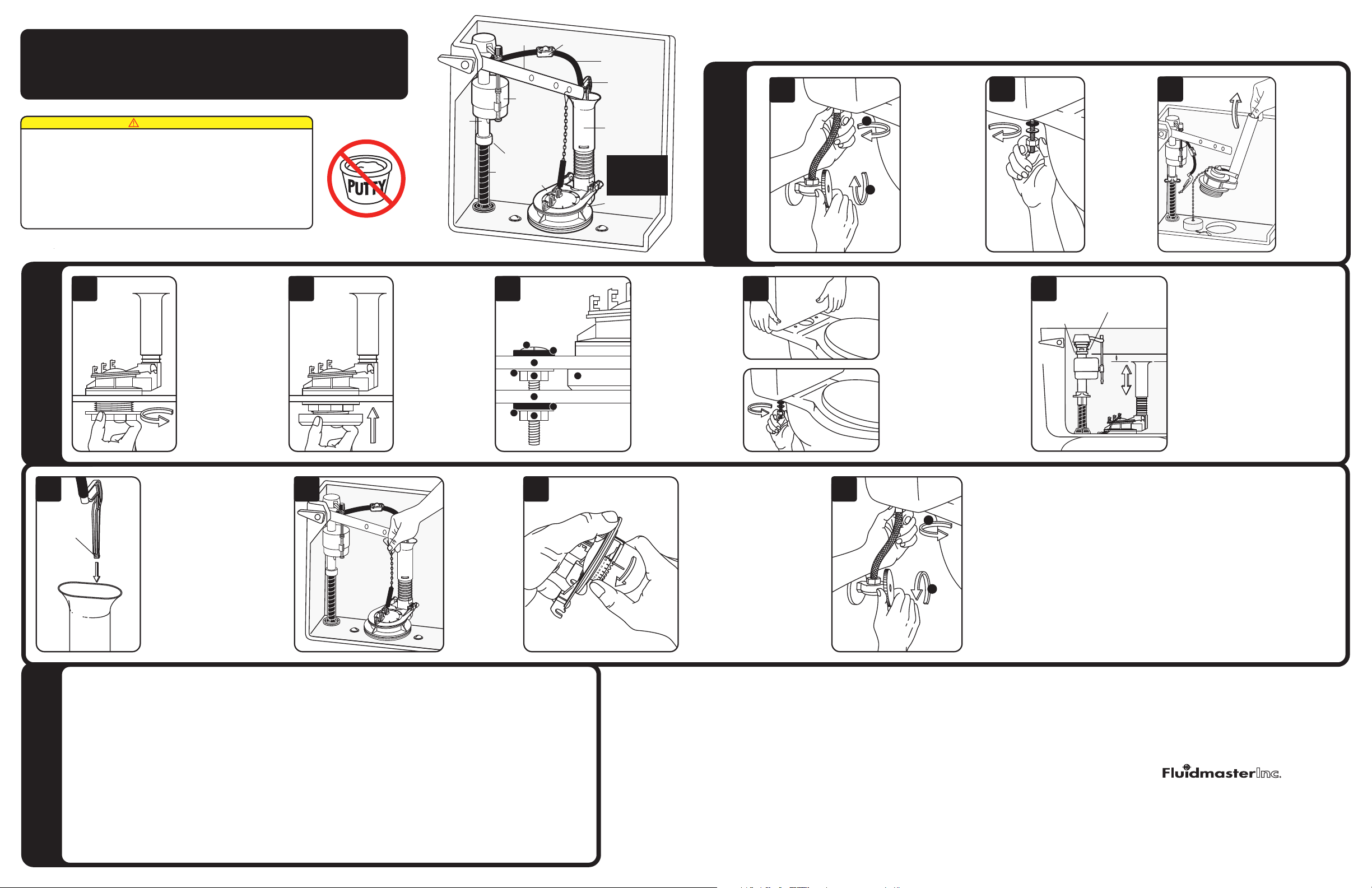
“C.L.”
MARK
1"
REFILL
PORT
TANK
HANDLE
METAL
PIECE
PART# 5 -3094 , Grev. 2, 08/11
®
FLUIDMASTER
540AKR
COMPLETE 3 INCH FLUSH VALVE & FLAPPER
REPAIR KIT INSTALLATION INSTRUCTIONS
WARNING
DO NOT USE IN-TANK DROP-IN TOILET BOWL CLEANERS CONTAINING BLEACH OR
DO NOT USE IN-TANK DROP-IN TOILET BOWL CLEANERS CONTAINING BLEACH OR
CHLORINE. Use of such products will: (1) RESULT IN DAMAGE to tank components and MAY CAUSE
CHLORINE. Use of such products will: (1) RESULT IN DAMAGE to tank components and MAY CAUSE
FLOODING and PROPERTY DAMAGE and (2) VOID FLUIDMASTER WARRANTY. Fluidmaster
FLOODING and PROPERTY DAMAGE and (2) VOID FLUIDMASTER WARRANTY. Fluidmaster
Flush 'n Sparkle Toilet Bowl Cleaning System is recommended for those choosing to use in-tank bowl cleaners
Flush 'n Sparkle Toilet Bowl Cleaning System is recommended for those choosing to use in-tank bowl cleaners
and WILL NOT VOID the FLUIDMASTER WARRANTY because it will not damage the components. DO
and WILL NOT VOID the FLUIDMASTER WARRANTY because it will not damage the components. DO
NOT overtighten nuts or tank/bowl may crack. Always use quality Fluidmaster parts when installing or
NOT overtighten nuts or tank/bowl may crack. Always use quality Fluidmaster parts when installing or
repairing. Fluidmaster will not be responsible or liable for use of non-Fluidmaster parts during installation or
repairing. Fluidmaster will not be responsible or liable for use of non-Fluidmaster parts during installation or
repair.
repair.
DO NOT USE
FILL
VALV E
BODY
SHANK
LOCK
RING
TANK
LEVER
FLOAT
CUP
FLAPPER
ROLLER CLAMP
REFIL L TUBE
REFILL
CLIP
OVERFLOW
PIPE
TANK SHOULD
LOOK LIKE THIS
WHEN SETUP
IS COMPLETE
FLUSH
VALV E
PREPARATION
1
Turn off water
supply (1).
2
Flush toilet and
2
remove excess
water from tank
with sponge. (2)
Unbolt tank
from bowl,
then lift the
tank. Remove
washers, nuts
and bolts.
3
Remove water
supply line from
bottom of toilet
1
fill valve.
Remove
rubber
washer and
locknut
from flush
valve
threads.
Remove old
flush valve.
Remove tank to bowl
1 2 3
gasket and nut from
bottom of threads of
new flush valve before
installing flush valve
in tank. Position the
Slide new tank to
bowl gasket over
nut with narrow side
facing down. Gasket
should cover the
nut completely.
A
overflow pipe toward
INSTALLATION
the back of the tank
but not over the bolt
holes. Thread large nut
D
onto the threads. Hand
tighten only. DO NOT
D
OVERTIGHTEN or tank
may crack.
The refill clip must be attached
6 7 98
to the top of the overflow pipe.
Place metal piece of refill clip
against the outside edge of the
pipe then press against the
overflow pipe. When the inside
prong clears the top edge of the
pipe, push the clip down. Attach
Connect the
flapper chain
to the tank
lever. Allow for
1/2" of slack
in the chain
when flapper
is closed.
refill hose to nipple of refill clip
and other end to nipple of the
fill valve. You many need to trim
the rubber hose.
B
C
E G
F
B
E
Correct order of bolts,
washers and nuts:
A) Bolt Head
B) Rubber Washer
C) Toilet Tank
D) Metal Washer*
E) Metal Hex Nut*
F) Toilet Bowl
G) Tank to Bowl Gasket
NOTE: Place metal
washers and hex nuts
onto brass bolts before
installing tank on bowl.
Remove flapper from flush valve
by pulling up frame of flapper one
side at a time.
The flapper is adjustable from 0
to 10. 0 is a quick flush, 10 is a
long flush, allowing you to adjust
the flush performance to match
your toilet’s original setting.
The tab on the white plastic
dome can be set to any of the
numbered notches. Pull on the
dome slightly and turn until the
tab is in the desired setting.
Optional: Before replacing the
4 5
tank on the bowl, place metal
washer and hex nut onto bolt
under tank and hand tighten until
snug hex nut.
Then place tank back on the
bowl so that tank to bowl gasket
fits evenly. Level tank. Under
the bowl attach rubber washer,
metal washer and metal hex
nut. Tighten the hex nuts under
the bowl evenly until the tank
is stable and doesn’t rock. DO
NOT OVERTIGHTEN or the tank
or bowl could break.
Reconnect water supply
line to the bottom of the
fill valve. Hand tighten
1
plastic nut of supply line
to fill valve shank. DO
NOT OVER TIGHTEN.
(1). Turn on the water
supply and check for
any leaking (2). If no
2
leaks appear perform
test flush. If leak appears
tighten nut just enough
to stop leak.
When installed the top of the
overflow pipe of the flush valve
must be at least 1" below the
C.L. mark of the fill valve.
NOTE: Top of the overflow
pipe should be below the
handle/lever hole of the toilet
tank and above the water level
of the tank when filled.
To adjust the height of the
overflow pipe, pull up or
push down.
MY FLAPPER CLOSES QUICKLY & I DON’T GET A COMPLETE FLUSH
• Check the flapper chain. If it looks loose, tighten it; if it looks straight, loosen it a bit and try flush again. Chain should have 1/2" of slack.
• Adjust the flapper setting to a higher number (See “Installation” step 8).
MY FLAPPER STAYS OPEN TOO LONG & I GET A DOUBLE-FLUSH
• Adjust the flapper setting to a lower number (See “Installation” step 8).
*NOTES:
• Installation Instruction #3: This Is Optional
D) Metal Washer*
E) Metal Hex Nut*
Not all toilets will fit together when metal washer and metal hex nut are used
TROUBLESHOOTING
Contact Fluidmaster for troubleshooting
help or Ask Bob on www.fluidmaster.com
30800 Rancho Viejo Road
San Juan Capistrano, CA 92675
www.fluidmaster.com
800-631-2011
PIEZA DE
METAL
PIEZ A# 5-3094, Gre v. 2, 08/11
MARCA
“C.L.”
1"
PUERTO DE
RECARGA
MANIJA
DEL
TANQUE
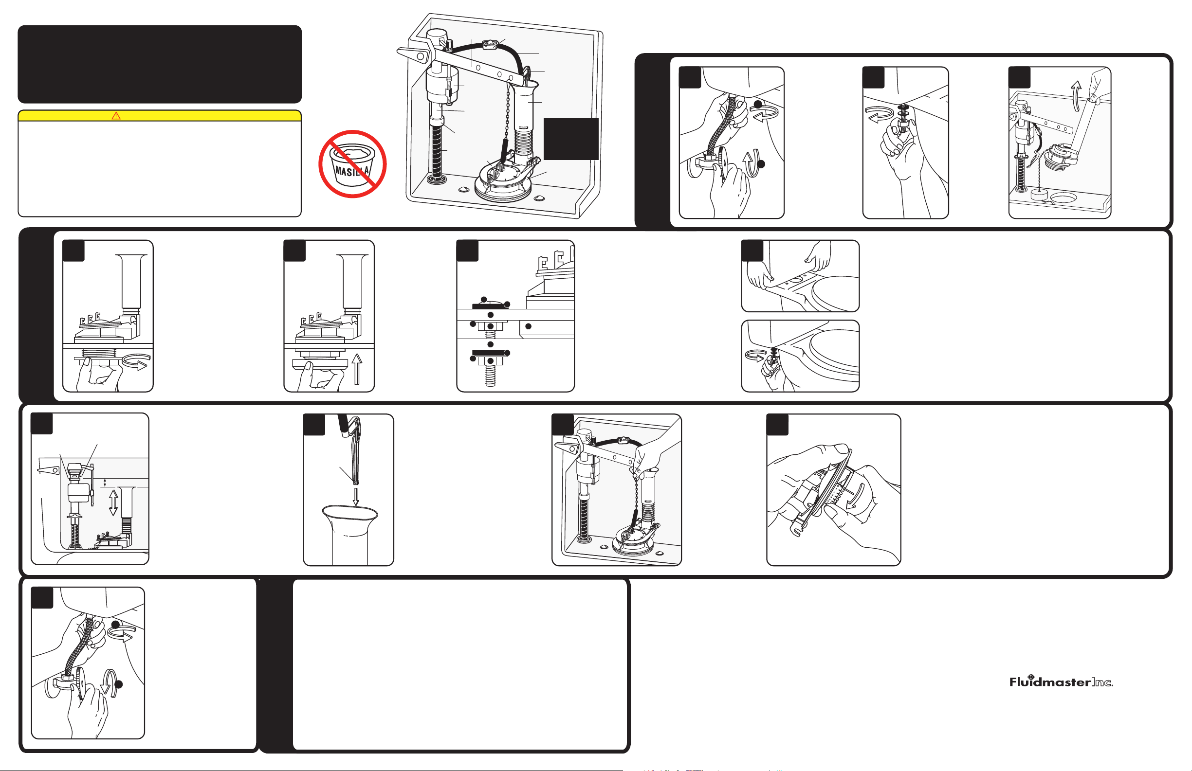
INSTRUCCIONES DE INSTALACIÓN DEL JUEGO
COMPLETO DE REPARACIÓN PARA FLOTADOR
Y VÁLVULA DE DESCARGA DE 7.6 CM
®
(3 PULG.) FLUIDMASTER
ADVERTENCIA
NO UTILICE LIMPIADORES DE TAZA DE INODORO QUE SE COLOQUEN EN EL TANQUE O SE SUMERJAN
NO UTILICE LIMPIADORES DE TAZA DE INODORO QUE SE COLOQUEN EN EL TANQUE O SE SUMERJAN
EN EL INODORO QUE CONTENGAN CLORO. El uso de este tipo de productos: (1) PRODUCIRÁ DAÑOS en los
EN EL INODORO QUE CONTENGAN CLORO. El uso de este tipo de productos: (1) PRODUCIRÁ DAÑOS en los
componentes del tanque, POSIBLES INUNDACIONES, así como DAÑOS A LA PROPIEDAD, y (2) ANULARÁ LA
componentes del tanque, POSIBLES INUNDACIONES, así como DAÑOS A LA PROPIEDAD, y (2) ANULARÁ LA
GARANTÍA DE FLUIDMASTER. Se recomienda el sistema de limpieza de taza de inodoro Flush ’n Sparkle de
GARANTÍA DE FLUIDMASTER. Se recomienda el sistema de limpieza de taza de inodoro Flush ’n Sparkle de
Fluidmaster para aquellos usuarios que desean utilizar limpiadores de tazas dentro del tanque SIN ANULAR la
Fluidmaster para aquellos usuarios que desean utilizar limpiadores de tazas dentro del tanque SIN ANULAR la
GARANTÍA DE FLUIDMASTER, ya que este sistema no daña los componentes. NO apriete demasiado las tuercas ya
GARANTÍA DE FLUIDMASTER, ya que este sistema no daña los componentes. NO apriete demasiado las tuercas ya
que el tanque o la taza podrían agrietarse. Siempre utilice piezas de repuesto de calidad de Fluidmaster durante la
que el tanque o la taza podrían agrietarse. Siempre utilice piezas de repuesto de calidad de Fluidmaster durante la
instalación o reparación. Fluidmaster no se hará responsable por el uso de productos que no sean de Fluidmaster durante
instalación o reparación. Fluidmaster no se hará responsable por el uso de productos que no sean de Fluidmaster durante
la instalación y reparación.
la instalación y reparación.
540AKR
NO USAR
ANILLO D E
SEGURIDAD
VÁSTA GO
PALA NCA
PARA TAN QUE
FLOTA DOR
CUERP O
DE VÁLVUL A
DE LLEN ADO
TAPÓ N
ABRAZA DERA DEL RODILLO
TUBO DE R ECARGA
SUJ ETADOR
DE RECA RGA
TUBER ÍA DE
DESBORDE
EL TANQUE DEBE
VERSE ASÍ UNA
VEZ QUE HAYA
TERMINADO LA
INSTALACIÓN
VÁLVUL A PARA
DESCA RGA DE
INODORO
1
PREPARACIÓN
Corte el
suministro
2
de agua (1).
2
Descargue el
inodoro y retire
el exceso de agua
del tanque con
una esponja. (2)
Retire la tubería
1
del suministro de
agua de la parte
Destornille
el tanque
de la taza,
luego
levante el
tanque.
Retire las
arandelas,
las tuercas
y los
pernos.
3
inferior de la
válvula de llenado
del inodoro.
Retire la
arandela de
goma y la
contratuerc
a de las
roscas de la
válvula para
descarga
de inodoro.
Retire la
válvula para
descarga
de inodoro
antigua.
1 2
INSTALACIÓN
5
Retire la empaquetadura que une
el tanque a la taza y la tuerca de
la parte inferior de las roscas
de la válvula para descarga
de inodoro nueva antes de
instalarla en el tanque. Coloque
el tubo de desborde hacia la
parte posterior del tanque pero
no sobre los orificios de los
pernos. Enrosque la tuerca
grande en las roscas. Apriete a
mano solamente. NO APRIETE
DEMASIADO ya que el tanque
podría agrietarse.
Una vez instalada, la parte superior
de la tubería de desborde de la válvula
de descarga debe estar al menos 2.5
cm (1 pulg.) por debajo de la marca
de nivel crítico (C. L.) de la válvula de
llenado.
NOTA: La parte superior de la tubería
de desborde debe estar por debajo del
orificio de la manija/palanca del tanque
del sanitario y por encima del nivel de
agua del tanque cuando está lleno.
Para ajustar la altura de la tubería de
desborde, tire hacia arriba o empuje
hacia abajo.
Coloque la
empaquetadura
3 4
que une el
tanque a la taza
nueva sobre la
tuerca, con el
lado angosto
hacia abajo. La
empaquetadura
debe cubrir
completamente
la tuerca.
A
D
D
B
C
E G
F
B
E
El sujetador de recarga se debe fijar en
6 7
la parte superior del tubo de desborde.
Coloque la pieza de metal del sujetador
de recarga contra el borde exterior del
tubo, luego presione contra el tubo de
desborde. Cuando la clavija interior
libere el borde superior del tubo,
empuje el sujetador hacia abajo. Fije
un extremo de la manguera de recarga
al manguito roscado del sujetador
de recarga y fije el otro extremo al
manguito roscado de la válvula de
llenado. Podría ser necesario cortar la
manguera de goma.
Orden correcto de los pernos, arandelas y
tuercas:
A) Cabeza del perno
B) Arandela de goma
C) Tanque del inodoro
D) Arandela de metal*
E) Tuerca hexagonal de metal*
F) Taza del inodoro
G) Empaquetadura que une el
tanque a la taza
NOTA: Coloque las arandelas de metal y las
tuercas hexagonales sobre los pernos de
latón antes de instalar el tanque en la taza.
Conecte la cadena
del tapón a la
palanca del tanque.
Asegúrese de que
la cadena tenga
1,27 cm de holgura
cuando el tapón
esté en la posición
de cerrado.
8
Opcional: Antes de volver a colocar el tanque en la
taza, coloque la arandela de metal y la tuerca
hexagonal sobre el perno que está debajo del
tanque y apriete a mano hasta que la tuerca quede
bien ajustada.
Luego vuelva a colocar el tanque sobre la taza, de
manera que la empaquetadura que une el tanque
a la taza calce perfectamente. Nivele el tanque.
Fije la arandela de goma, la arandela de metal y
la tuerca hexagonal de metal debajo de la taza.
Apriete las tuercas hexagonales debajo de la taza
uniformemente hasta que el tanque quede estable
y no se balancee. NO APRIETE DEMASIADO ya
que el tanque o la taza podrían agrietarse.
Retire el tapón de la válvula para
descarga de inodoro jalando lentamente
el marco del tapón.
El tapón se ajusta de 0 a 10; 0
corresponde a una descarga rápida, 10
corresponde a una descarga prolongada.
Esto le permite ajustar el rendimiento de
descarga para igualar la configuración
de su inodoro original. La lengüeta
en el domo plástico blanco se puede
configurar a cualquiera de las muescas
enumeradas. Jale el domo suavemente
y gírelo hasta que la lengüeta esté en la
configuración deseada.
9
Vuelva a conectar la línea
de suministro de agua a la
parte inferior de la válvula
1
de llenado. Ajuste a mano
la tuerca plástica de la línea
de suministro al vástago
de la válvula de llenado. NO
LA AJUSTE EN EXCESO.
MI TAPÓN SE CIERRA MUY RÁPIDO Y NO PUEDO REALIZAR UNA DESCARGA COMPLETA
• Revise la cadena del tapón. Si está suelta, tensiónela; si está tensa, aflójela un poco y vuelva a
realizar la descarga. La cadena debe tener 1,27 cm de holgura.
• Ajuste la configuración del tapón al número más alto (Consulte el paso 8 en “instalación”).
MI TAPÓN PERMANECE ABIERTO POR MUCHO TIEMPO Y SE PRODUCE UNA DESCARGA DOBLE
• Ajuste la configuración del tapón al número más bajo (Consulte el paso 8 en “instalación”).
Póngase en contacto con Fluidmaster
para obtener ayuda en la solución
de problemas o pregúntele a Bob en
www.fluidmaster.com
(1). Abra el suministro de
2
agua y busque posibles
pérdidas (2). Si no hay
pérdidas, realice una
descarga de prueba. Si hay
pérdidas, ajuste la tuerca
justo lo suficiente para
eliminar las pérdidas.
*NOTAS:
• Instrucción de instalación número 3: Esto Es Opcional
D) Arandela metálica*
E) Tuerca hexagonal metálica*
No todos los sanitarios encajarán cuando se use una arandela metálica y una tuerca hexagonal
metálica
SOLUCIÓN DE PROBLEMAS
30800 Rancho Viejo Road
San Juan Capistrano, CA 92675
www.fluidmaster.com
800-631-2011
 Loading...