

Fluidmaster 400AKR Installation Instructions Manual
INSTALLATION
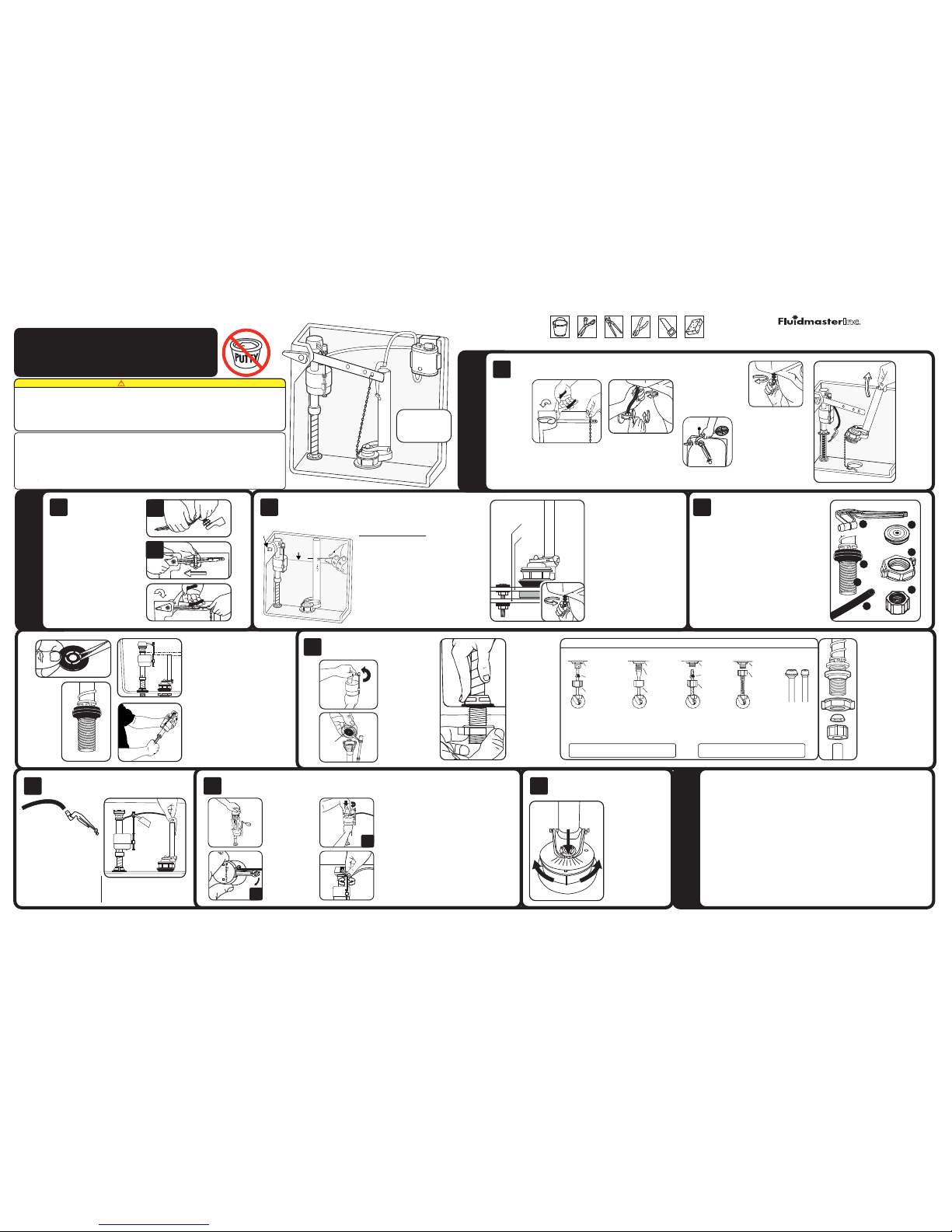
START HERE
TROUBLESHOOTING
G
F
DO NOT USE
Remove old parts from tank
TOOLS
NEEDED
TANK
BOWL
A
C
B
D
E
MIN
MAX
1
2
3
4
5
6
7
8
9
242
SEAL
CAUTION: Overtightening LOCKNUT or COUPLING
NUT could result in breakage and potential flooding.
CAUTION: DO NOT use CONE WASHER with
PLASTIC SUPPLY LINE or METAL SPIRAL TUBING.
DO NOT use plum ber’s putt y to seal thes e fittings.
These par ts must be used a s illustra ted to insure w atertigh t connecti ons.
LOCKNUT
CONE
WASHER
COUPLING
NUT
WATER
SHUTOFF
METAL/CO PPER
FLARED TUBING
Use Flui dmaster c oupling
nut and co ne washer t o
replac e existi ng part s.
Water sup ply tube must
extend 1 /2 inch in side
thread ed shank o f valve.
LOCKNUT
FLAT
WASHER
COUPLING
NUT
WATER
SHUTOFF
METAL FLANGED
TUBING
Use existin g
coupling nut a nd
existing flat washer.
LOCKNUT
SPIRAL
CONE
WASHER
COUPLING
NUT
WATER
SHUTOFF
METAL SPIRAL
TUBING
Use exis ting
spiral cone
washe r.
PLASTIC O R METAL
COMPRESSION
BALL TUBING
Do not use F luidmaster's coupling
nut and th e cone
washer o n plasti c
or metal t ubing as
shown.
LOCKNUT
COUPLING
NUT
WATER
SHUTOFF
VINYL/BRAIDED
CONNECTOR
Captiv e cone was her
alread y include d. No
additi onal was hers
required.
Remove ba ll cock
from tan k.
Remove ta nk
lid. Use a
pencil to m ark
the wate r level
of the tan k.
Then flu sh out
tank.
Unhook flapp er chain from tank le ver.
Remove tank le ver by loosening lock nut
inside tank . This is a reverse th read. Turn
nut in direct ion shown. Pull lever fr om tank.
Remove
tank to
bowl
gasket
from unde r
tank.
Loosen
flush val ve
locknu t,
then lif t
flush val ve
out of tan k
Flush N Sparkle System
Sold Seperately
Turn off wa ter supply.
(Clock wise) Place a to wel
on floor un der the water
supply connection at tank.
Remove exces s water
from bott om of tank
with a spong e. Remove
water suppl y line from
bottom of f ill valve.
Remove lock nu t of fill
valve from u nder tank.
Unbolt t ank from
bowl. Li ft tank of f of
bowl. La y tank on its
side on a sa fe secure
surfa ce. Remove
washer s, nuts and
bolts.
Place fi ll valve in ta nk, do not inst all.
Set top of f ill valve eve n with or 1/2"
above top o f tank. Remo ve fill valve
from tan k to adjust hei ght.
Adjust height of fill v alve by holding
lower shank with righ t hand and top
with left hand. Turn lower sh ank in
or out of the valve body. Plac e valve
in tank and check heigh t again. The
Critical Level Ma rk - identified by “C.L.”
on valve-MUST be 1" above th e top of
the overflow pipe. T his is a plumbing
code.
Do not move lock ring. It hold s the
valve body and shank to gether under
pressure. Do not interc hange body with
old shank.
Before inst alling fill
valve, remo ve the
valve cap as sembly.
Push flo at up with
right ha nd. Grip and
hold sha ft under
float wi th right han d.
With le ft hand,
twis t cap and lever
counterclockwise
1/8" o f a turn to
unlock. Let ca p
assemb ly hang on
adjustment screw.
Flush ing Out the
Debris: Hold a cu p
over the u ncapped
valve t o prevent
splas hing. Turn
water su pply full
on and of f a few
times. L eave wate r
supply o ff. Check
for lea ks. Tight en
nuts ju st enough to
stop leaking.
Use char t to determi ne
which t ype of water
supply yo u have. Use the
appropriate assembly
parts a s required to
properly reconnect the
water sup ply. Do not use
plumber s putty to s eal
these fi ttings. ( Teflon
tape is optional). With
correc t washers in p lace
tighte n coupling nut .
HAND TIG HTEN ONLY.
CAUTIO N: Do not use
Fluidma ster cone wa sher
with pla stic suppl y line or
metal spiral tubing.
Replac e valve ca p assemb ly
. A)Place c ap assembl y
on top of gr ay valve body b y aligning ca p arm and
adjustm ent rod nex t to refill hos e. B)Press dow n on
top cap ro tating top a nd arm clock wise to lock ed
position.
Submerge float cup
. Turn on water supply.
IMPORTANT: Submerge float cup un der water for
30 seconds. The n set the float cup to desired l evel.
When adjusting f loat cup flush the tank firs t. Then
make adjustment w hile tank is filling. Set wa ter to
the mark you made in t ank. Valve will shut off at n ew
setting. To raise w ater level turn adjustmen t screw
clockwise. To lower se tting turn counter clo ckwise.
Hint:
If you twist knob 8 t imes float moves 1/2"
PART# 4-765, Grev. 5, 11/11
DO NOT USE IN-TANK DROP-IN TOILET BOWL CLEANERS CONTAINING BLEACH OR CHLORINE. Use of such products will: (1) RESULT
IN DAMAGE to tank components and MAY CAUSE FLOODING and PROPERTY DAMAGE and (2) VOID FLUIDMASTER WARRANTY.
Fluidmaster Flush 'n Sparkle Toilet Bowl Cleaning System is recommended for those choosing to use in-tank bowl cleaners and WILL NOT VOID the
FLUIDMASTER WARRANTY because it will not damage the components. DO NOT overtighten nuts or tank/bowl may crack. Always use quality
Fluidmaster parts when installing or repairing. Fluidmaster will not be responsible or liable for use of non-Fluidmaster parts during installation or repair.
LIMITED FIVE-YEAR EXPRESS WARRANTY
Subject to the “Exclusions” set forth below, Fluidmaster Inc. promises to the consumer to repair, or at the option of Fluidmaster Inc. to replace any
part of this plumbing product which proves to be defective in workmanship or materials under normal use for five years from the date of purchase. All
costs of removal, transportation and reinstallation to obtain warranty service shall be paid by the consumer. During this “Limited Five Year Express
Warranty,” Fluidmaster Inc. will provide, subject to the “Exclusions” section set forth below, all replacement parts free of charge, necessary to correct
such defects. This “Limited Five Year Warranty” is null and void if this plumbing product has not been installed and maintained in accordance with all
written instructions accompanying the product, and if non-Fluidmaster Inc. parts are used in installation.
EXCLUSIONS: FLUIDMASTER INC. SHALL NOT BE LIABLE FOR INCIDENTAL OR CONSEQUENTIAL DAMAGES, INCLUDING COSTS OF INSTALLATION, WATER
DAMAGE, PERSONAL INJURY OR FOR ANY DAMAGES RESULTING FROM ABUSE OR MISUSE OF THE PRODUCT, FROM OVERTIGHTENING OR FROM FAILURE
TO INSTALL OR MAINTAIN THIS PLUMBING PRODUCT IN ACCORDANCE WITH THE WRITTEN INSTRUCTIONS, INCLUDING USE OF NON-FLUIDMASTER PARTS.
DO NOT USE IN-TANK DROP-IN TOILET BOWL CLEANERS CONTAINING BLEACH OR CHLORINE. USE OF SUCH PRODUCTS WILL RESULT IN DAMAGE TO TANK
COMPONENTS AND MAY CAUSE FLOODING AND PROPERTY DAMAGE. USE OF SUCH PRODUCTS WILL VOID THIS WARRANTY.
WARNING
FLUIDMASTER
®
400AKR
COMPLETE TOILET REPAIR KIT
INSTALLATION INSTRUCTIONS
A) Refill Clip D) Lock Nut
B) Refill Hose E) Coupling Nut
C) Shank & Cone F) Threa ded Shank
Washer G) Shank Washer
Pull Shan k and cone wash er off the en d of the
Refill Clip. This will release all the assembly
parts.
Push the c one washer fr om the center o f
shank wa sher with your t humb or cut the f our
connec tions bet ween the shan k & cone washer
with sci ssors. Se t cone washer a side.
Under tan k, thread lar ge plastic
hex nut ont o threads of flu sh valve.
Tighten l ock nut 1/2 turn b eyond
hand tigh t. Place tan k to bowl
gasket on b ottom of flu sh valve.
Gasket sh ould cover hex nu t.
Place a ru bber washer o n tank
bolts. P lace tank bo lt through
hole in ta nk. (optiona l step: Under
tank, pl ace a metal w asher and
hex nut, t ighten hex nu t.) Set tank
onto bow l. Place rubb er washer,
metal w asher and hex nu t on to
bolts un der bowl. Tig hten hex nut s
evenly un til tank is sn ug on bowl
and does n ot rock.
Before ins talling flush va lve remove tank t o bowl
gasket and h ex nut from botto m of flush valve.
Set flush va lve with flush va lve seal into ope ning
inside of ta nk.
Cutting t he Overflow pip e
Measure 1" down f rom the bottom ed ge of the
tank lever ho le and make a mark on the t ank wall.
If the new mark o n the tank is above th e water
level mark , cut the overflow p ipe at the new mark.
If the wat er level mark i s equal to or abo ve the
new mark o n the tank, th e water level i s set too
high. Low er the water le vel 1/2" belo w the new
mark on th e tank. Cut th e overflow p ipe before
you inst all the flush v alve. Use a pip e cutter or
hacksa w blade to cut ov erflow pip e.
If your tan k lever has an y bends in
it, foll ow step (2A). If i t does not
have any b ends in it skip t o step
(2B).
2A) To bend lever st art bend 2" out
from point le ver enters tank. B end
to match old le ver. Do not bend arm
quickly or ba ck and forth repe atedly.
2B) Push lev er through ta nk hole.
Slide loc k nut onto lev er arm round
flange f irst. Thre ad nut until s nug.
Do not over tighten. L ock nut is a
reverse thread.
Attach o ne end of REFILL
HOSE to REFIL L CLIP. Place
clip on right s ide of overflow
pipe. Att ach other end of hos e
to nipple on fil l valve with a
slight arch ing of hose. (See
picture at r ight.) Cut tube as
necessa ry. Do not shove ref ill
tube down over flow pipe. Thi s
will cause w ater loss.
30800 Ran cho Viejo Road, S an Juan Capis trano, CA 92675
www.Fluid master.com • 80 0-631-20 11
Contact F luidmaster fo r troubleshoot ing help or Ask Bob o n www.fluidma ster.com
FILL
VALVE
FLUSH
VALVE
FLAPPER
OVERFLOW
PIPE
REFILL TUBE
REFILL
CLIP
TANK
LEVER
Tank Leve r
Fill Valve
Fill Valve Con t.
Flushing the Fill Valve, reconnect top & Adjust the Water Level
Flush Valve Preparing Fill Valve
Check Adjustable
Flapper Setting
OVERFLOW
PIPE
FILL
VALVE
WATER
LEVEL
TANK LEVER
HOLE
Place Sh ank
washer o nto
threaded
shank of f ill
valve, f lat
side up.
Then pla ce
fill val ve in
tank.
Correct se t up of refill hose and
refill clip on overflow pipe.
FILL VALVE WILL NOT TURN OFF
• IMPORTA NT: Sand and rust moves thro ugh
water pi pes. Alwa ys clear de bris from wa ter
lines. Re peat the s teps to flus h out the val ve
(see Step 6 ).
FILL VALVE WILL NOT TURN ON
• IIf fill va lve has been in use for so me time,
And float cup do es not drop when flushi ng the
tank: Replac e 242 seal.
• If fill v alve is new, Remove to p cap and check
for debris. I f you find debris cl ean out. If no
debris foun d: Place a coffe e cup upside down
over uncapp ed valve and tur n on water full.
If strong fl ow: replace va lve. If flow is wea k:
partial b lockage fur ther down in val ve, at shut
off or in wat er supply line.
WATER LEVEL IN BOWL IS TOO LOW
• Mak e sure the ref ill hose is su pplying w ater
down the overflow pipe.
• Water l evel in tank may be to o low. Raise
water level t o 1/2” below top of o verflow pipe.
• Flap per may be closin g too soon. Give fl apper
chain approx imately 1/2 “ of sl ack. Adjust
flapper to higher setting.
• If you r toilet is 3.5 g allons per f lush or large r,
the flap per in this ki t may not be the c orrect
flapper.P ick up a 501 Har sh Water fl apper or
504 all ru bber flapp er by Fluidma ster.
CAUTION: Do n ot shove refill tu be down
overflow p ipe. This will ca use loss of water
from tank. M ake sure the end of t he refill tube
is higher tha n the water level o f the tank.
Place fill valve in
tank. Make sure
lid will sit on top
of tank. Align
fill valve nipple
to face parallel
with back wall of
tank. Press down
on shank while
tightening locknut.
Hand-tighten
only.
Bucket Scissors Channe l
Locks
Adjus table
Pliers
Hack Saw Sponge
A
B
5
5
6
2A
2B
2 3 4
1
The Adju stable fla pper
is set on # 9 from the
factor y. To adjust,
rotat e rubber flap per
left or r ight to posi tion
# in front o f chain to
get desi red flush.
The high er the number
setti ng the longer t he
flush. T he lower the
number se tting, the
less water used.
7
TANK SHOULD
LOOK LIKE THIS
WHEN SET UP IS
COMPLETE
30800 Ran cho Viejo Road, S an Juan Capis trano, CA 92675
www.Fluid master.com • 80 0-631-20 11
Póngas e en contac to con Flui dmaster pa ra obtene r ayuda en la s olución de pr oblemas
o pregún tele a Bob en w ww.fluidm aster.com
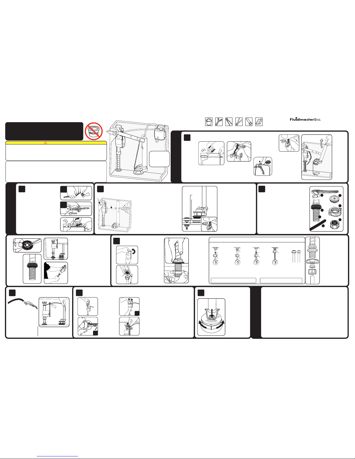
INSTALACIÓN
PREPARACIÓN
SOLUCIÓN DE PROBLEMAS
G
F
Retire las piezas antiguas del tanque
A
C
B
D
E
MIN
MAX
1
2
3
4
5
6
7
8
9
242
SELLO
Retire e l flotador d el
tanque.
Retire l a tapa
del tanque.
Use un láp iz
para mar car el
nivel de a gua
del tanq ue. A
continuación,
descar gue el
tanque.
Desconec te la cadena del ta pón de la palanca
del tanque. Retire la palanca del tanque
soltando l a contratuerc a al interior del
tanque. Ést a es una rosca inve rtida. Gire la
tuerca en la di rección que se mues tra. Tire
de la palanca del tanque.
Retire la
empaquetadura
que une el
tanque con la
taza de debajo
del tanque.
Afloje la
contratuerca de
la válvula para
descarga de
inodoro, luego
retire la válvula
para descarga
de inodoro
del tanque
levantándola.
El sistema Flush 'n Sparkle
se vende por separado
Corte e l suministr o de
agua. (En d irección d e
las mane cillas del r eloj)
Coloque u na toalla en e l
piso deb ajo de la conex ión
del sumin istro de agua a l
tanque.
Retire e l exceso de agu a
del fondo d el tanque co n
una espon ja. Retire l a
tuberí a de suministr o de
agua de la p arte infer ior
de la válv ula de llena do.
Retire l a contratu erca de
la válvu la de llenad o de la
parte inferior del tanque.
Destor nille el tan que
de la taz a. Retire e l
tanque levantándolo
de la taz a. Deje el
tanque d e costado en
una superficie segura.
Retire l as arandel as,
las tuer cas y los
pernos.
Coloque l a válvul a de llenado e n el tanque,
no la inst ale. Colo que la part e superior d e
la válvu la de llena do de manera u niforme
a 1,27 cm por so bre la par te superio r del
tanque . Retire la v álvula de ll enado del
tanque p ara ajust ar la altur a.
Ajuste la altura d e la válvula de llenado al
sostener el vást ago inferior con la mano
derecha y la part e superior con la otra. Gire
el vástago infer ior hacia adentro o hacia
fuera del cuerpo de la v álvula. Coloque la
válvula en el tanqu e y vuelva a revisar la
altura. La marc a de nivel crítico (que se
reconoce como “CL” en la válvula d e llenado)
DEBE estar al menos 2, 54 cm por encima de
la parte superior d el tubo de desborde. Este
es un código de plomería .
No mueva el aro de segur idad, ya que éste
mantiene unidos b ajo presión el cuerpo de l a
válvula y la espig a. No intercambie el cu erpo
con una espiga vie ja.
Antes d e instal ar la
válvul a de llenado , retire
el ensam blado de la t apa
de la válv ula.
Empuje el flot ador hacia
arriba con l a mano derecha.
Agarre y sos tenga la
espiga bajo e l flotador con
la mano dere cha. Con la
mano izquier da gire la tapa
y la palanc a en dirección
contrari a a las manecill as
del reloj un oc tavo de giro
para desbl oquear. Deje que
el ensambla do de la tapa
superior quede suspendido
sobre el torn illo de ajuste.
Lave los desechos:
Sosten ga una taza
sobre la vá lvula
destap ada para
que no salp ique
agua. Abr a y cierre
complet amente el
suminis tro de agua
unas cuantas veces.
Deje el sum inistro
de agua cer rado.
Verifiq ue que no
haya fug as. Apriet e
las tuer cas sólo
lo sufici ente para
evitar fugas.
Use la tab la para de terminar
el tipo de su ministro d e agua
que tien e. Utilice l as pieza s
de ensam blaje ade cuadas
según se r equiere pa ra volver
a conect ar corre ctament e el
suminis tro de agua . No utilice
masill a de plomero p ara
sellar e stos cone ctores. (L a
cinta Tef lon es opcio nal). Una
vez colo cadas las a randela s
correc tas, ajus te la tuerc a
de acoplamiento. APRIETE
A MANO SO LAMENT E.
PRECAU CIÓN: No util ice la
arandela cónica Fluidmaster
en una líne a de suminis tro de
plásti co o un tubo de m etal
en espir al.
Vuelva a c olocar el e nsamble de l a tapa de la vá lvula.
A) Coloqu e el ensambl ado de la ta pa sobre el cu erpo de
la válvu la gris ali neando el br azo de la ta pa y la varil la
de ajust e con la mangu era de rec arga. B) Pre sione haci a
abajo la t apa super ior girand o la parte su perior y el br azo
en direc ción de las ma necilla s del reloj a l a posición d e
bloqueo.
Sumerja la taz a flotante. Abra el s uministro de agua.
IMPORTA NTE: Sumerja la t aza flotante b ajo el agua durante
30 segundos. Lueg o coloque la taza fl otante hasta el ni vel
deseado. Desca rgue el tanque primero p ara ajustar la ta za
flotante. Lue go haga los ajustes mien tras se llena el tanqu e.
Coloque agua hast a la marca que hizo en el t anque. La
válvula se cerr ará en el nuevo ajuste. P ara elevar el nivel del
agua, gire el tornil lo de ajuste en dirección d e las manecillas
del reloj. Para re ducir el ajuste, gire el tor nillo en dirección
contraria a la s manecillas del reloj . Consejo: Si gira la peril la
8 veces el flotad or se mueve 1,27 cm
PART# 4-765, Grev. 5, 11/11
NO UTILICE LIMPIADORES DE TAZA DE INODORO QUE SE COLOQUEN EN EL TANQUE O SE SUMERJAN EN EL INODORO QUE CONTENGAN
CLORO. El uso de este tipo de productos: (1) PRODUCIRÁ DAÑOS en los componentes del tanque, POSIBLES INUNDACIONES, así como DAÑOS A LA
PROPIEDAD, y (2) ANULARÁ LA GARANTÍA DE FLUIDMASTER. Se recomienda el sistema de limpieza de taza de inodoro Flush ’n Sparkle de Fluidmaster
para aquellos usuarios que desean utilizar limpiadores de tazas dentro del tanque SIN ANULAR la GARANTÍA DE FLUIDMASTER, ya que este sistema no daña
los componentes. NO apriete demasiado las tuercas o el tanque, ya que la taza se puede agrietar. Siempre utilice piezas de repuesto de calidad de Fluidmaster durante
la instalación o reparación. Fluidmaster no se hará responsable por el uso de productos que no sean de Fluidmaster durante la instalación y reparación.
GARANTÍA EXPRESA LI MITADA POR CINCO AÑOS
Fluidmaster, Inc. le promete al consumidor, sujeto a las “Exclusiones” estipuladas abajo, reparar, o a la opción de Fluidmaster, Inc., reemplazar cualquier parte de
este producto de fontanería cuya mano de obra o materiales sean defectuosos bajo condiciones de uso normales durante cinco años a partir de la fecha de compra.
Todos los costos de desmontaje, transporte y reinstalación relacionados con el servicio bajo garantía deberán ser pagados por el consumidor. Durante esta “Garantía
Limitada Expresa de Cinco Años”, Fluidmaster, Inc. proporcionará sin costo alguno, sujeto a la sección “Exclusiones” estipulada abajo, todos los repuestos que sean
necesarios para corregir dichos defectos. Esta “Garantía Limitada de Cinco Años” quedará anulada si este producto de fontanería no ha sido instalado y mantenido
conforme a todas las instrucciones escritas que se proporcionan con el mismo y si se utilizaron piezas que no son de Fluidmaster Inc. en la instalación.
EXCLUSIONES: FLUIDMASTER INC. NO SE RESPONSABILIZA POR DAÑOS INCIDENTALES O INDIRECTOS, INCLUYENDO COSTOS DE INSTALACIÓN, DAÑOS CAUSADOS POR
AGUA, LESIONES PERSONALES O CUALQUIER OTRO DAÑO QUE OCURRA DEBIDO AL ABUSO O USO INDEBIDO DEL PRODUCTO, ASÍ COMO POR APRETAR EXCESIVAENTE,
POR EL USO DE PIEZAS QUE NO SON DE FLUIDMASTER INC., O POR NO INSTALAR O MANTENER ESTE PRODUCTO DE PLOMERÍA CONFORME A LAS INSTRUCCIONES
ESCRITAS, LO QUE INCLUYE EL USO DE PIEZAS QUE NO SON FLUIDMASTER. NO UTILICE LIMPIADORES COLOCADOS EN EL TANQUE DEL SERVICIO SANITARIO QUE
CONTENGAN BLANQUEADOR O CLORO. EL USO DE ESTOS PRODUCTOS DAÑARÁ LOS COMPONENTES DEL TANQUE Y PODRÍA CAUSAR DESBORDAMIENTO Y DAÑOS A LA
PROPIEDAD. EL USO DE DICHOS PRODUCTOS ANULARÁ ESTA GARANTÍA.
WARNING
A) Sujetador d e recarga E) Tuerc a de acoplamiento
B) Manguera de r ecarga F) Arandela de
C) Arandela y c ono espiga roscada
D) Contratuer ca G) Arandela de e spiga
Jale y retir e la espiga y la arand ela cónica del ex tremo
del sujetad or de recarga. Es to liberará toda s las
piezas de en samblaje.
Empuje co n el pulgar la ar andela cóni ca desde el
centro d e la arandel a de espiga o cor te con tijer as
las cuat ro conexion es entre la s arandela s de espiga
y cónica . Deje a un lado la a randela có nica.
Bajo el tanque, enr osque la tuerca hexa gonal
plástica gra nde en las roscas de la v álvula
para descarg a de inodoro. Apriete la
contratuerc a dándole hasta la mi tad de
giro más que el ajust e manual. Coloque
la empaquetadur a que une el tanque a la
taza en la par te inferior de la válv ula para
descarga de ino doro. La empaquetadur a
debe cubrir la tuer ca hexagonal.
Coloque una ara ndela de goma sobre lo s
pernos del tan que. Coloque el perno d el
tanque a travé s del orificio del t anque.
(paso opciona l: Bajo el tanque, col oque una
arandela de metal y la tuerca hexagonal;
apriete bien la tuerca hexagonal). Coloque
el tanque sobre l a taza. Coloqu e la arandela
de goma, la aran dela de metal y la tue rca
hexagonal en lo s pernos bajo la ta za. Apriete
las tuercas hexagonales uniformemente
hasta que el t anque quede bien ajus tado
sobre la taz a y no se balancee.
Antes de ins talar la válv ula para desc arga de inodoro
retire la em paquetadura q ue une el tanque a la t aza y la
tuerca hex agonal en la par te inferior de l a válvula para
descarga d e inodoro. Ajus te la válvula pa ra descarga
de inodoro co n el sello de válvu la para descar ga en la
abertura dentro del tanque.
Corte del tubo de desborde
Mida 2,54 c m desde el bord e inferior de l orificio d e la
palanc a del tanque y ha ga una marca e n la pared del
tanque. Si l a nueva marc a en el tanque s e encuentra
por encima d e la marca del n ivel de agua, c orte el tubo
de desbor de en la nueva ma rca.
Si la marc a del nivel de a gua está a la mi sma altura
o sobre la nu eva marca e n el tanque, el n ivel de agua
está muy a lto. Desci enda el nive l de agua 1,27 cm po r
debajo de l a nueva marc a en el tanqu e. Corte el t ubo
de desbor de antes de in stalar la v álvula pa ra descar ga
de inodor o. Use una cor tadora de t ubos o la hoja de
una sierr a de mano par a cortar el t ubo de desbo rde.
Si su pala nca del tanq ue tiene dobl eces,
siga con e l paso (2A). Si no t iene doble ces
en ella, c ontinúe con e l paso (2B).
2A) Para dob lar la palanc a, comience
doblando 5,0 8 cm hacia fuera d esde el
punto donde l a palanca entr a en el tanque.
Doble hast a dejar igual que l a palanca
antigua. N o doble el brazo r ápidamente ni
hacia dela nte y hacia atrá s repetidas v eces.
2B) Presione la p alanca a travé s del orificio
del tanque. D eslice la contr atuerca a la brid a
redonda del b razo de la palan ca primero.
Gire la tuerc a hasta lograr u n ajuste ceñido.
No apriete demasiado. La contratuerca tiene
una rosca in vertida.
Una el extr emo de la MANGUE RA
DE RECARGA a l SUJETADOR DE
RECARGA . Coloque el suje tador
al costad o derecho del tub o de
desborde. C onecte el otr o extremo
de la manguer a al manguito
roscado de l a válvula de lle nado
arqueando la manguera levemente.
(Consulte la i magen a la derec ha.)
Corte el tu bo si es necesar io. No
empuje el tubo d e recarga baj o el
tubo de desbo rde. Esto provo cará
pérdida de ag ua.
VÁLVULA DE
LLENADO
VÁLVULA
PARA
DESCARGA
TAPÓN
TUBERÍA DE
DESBORDE
TUBO DE RECARGA
SUJETADOR DE
RECARGA
PALANC
A DEL
TANQUE
Palanca del tanque
Válvula de llenado
Válvula de llenado (cont.)
Descargue la válvula para descarga de inodoro, vuelva a conectar la parte
superior y ajuste el nivel de agua
Válvula para
Descarga
Preparación Válvula
de Llenado
Revise el ajuste
del tapón ajustable
TUBO DE
DESBORDE
VÁLVULA
DE LLENAD O
NIVEL DE
AGUA
ORIFICIO DE L A
PALANCA D EL TANQUE
Coloque la
arandela de
espiga sobre la
espiga roscada
de la válvula
de llenado con
el lado plano
hacia arriba.
Luego coloque
la válvula de
llenado en el
tanque.
Corrij a el ajuste de l a manguer a de
recar ga y del sujet ador de rec arga en
el tubo de desborde.
LA VÁLVULA DE LLENADO NO SE CIERRA
• IM PORTANTE: Por la s tuberías de agua pas a
arena y óx ido. Siempr e limpie los d esechos
de las lín eas de agua . Repita lo s pasos par a
descar gar la vál vula (consul te el paso 6).
LA VÁLVULA DE LLENADO NO SE ABRE
• Si la válvula de llen ado ha estad o en uso
por un tiemp o y la taza flo tante no ca e al
descar gar el tanque: R eemplace el s ello 242.
• Si la válvula de ll enado es nue va, retir e la
tapa de l a parte sup erior y rev ise si hay
desechos. Si encuentra desechos, retírelos.
Si no encue ntra des echos: Col oque una ta za
de café de f orma inver tida sob re la válvu la
sin tapa y a bra el agua p or complet o. Si el
flujo es f uerte: Ree mplace la v álvula. S i el
flujo es dé bil: Bloqu eo parcia l en otra par te
de la válv ula, en el ci erre o en la lín ea de
suministro de agua.
EL NIVEL DE AGUA EN LA TAZA
ES DEMASIADO BAJO
• Asegúrese de que l a manguer a de recarg a
suminis tre agua a tr avés del tub o de desbord e.
• Puede que el nivel d e agua en el ta nque esté
demasi ado bajo. Au mente el niv el de agua a
1,27 cm por debaj o del tubo de desbor de.
• Puede que el tapón se cie rre demasia do pronto.
Déle 1,27 cm má s de holgura a la ca dena del
tapón. Aj uste el tapón a u na configura ción más
alta.
• Si su inodoro es de 13,2 5 litros po r descarg a
o más, el ta pón en este k it puede qu e no sea
el corre cto. Busqu e el tapón pa ra agua dura
501 o el tap ón comple tamente d e goma 504 de
Fluidmaster.
PR ECAUCIÓN: N o empuje el tu bo de recar ga
bajo el tu bo de desbor de. Esto pro vocaría
pérdid a de agua del ta nque. Ase gúrese de qu e
el extr emo del tubo d e recarga e sté por enc ima
del nive l del agua del t anque.
Coloque la válvula d e
llenado en el tanque.
Asegúrese de que
la tapa se asent ará
en la parte superio r
del tanque. Alinee el
manguito roscado
de la válvula de
llenado de manera
que quede paralelo a
la pared posterior d el
tanque. Presione la
espiga hacia abajo,
a la vez que aprieta
la contratuerc a.
Apriétela sólo c on
las manos.
cubeta tijeras alicates
para fil tros
llave
inglesa
Hack sie rra
de mano
Esponja
A
B
5
5
6
2A
2B
2 3 4
1
El tapón a justable e stá
ajusta do en #9 de fáb rica.
Para aju starlo, gir e
el tapón d e goma a la
izquier da o derecha a l #
de posici ón al frente d e
la caden a para obten er la
descar ga desead a.
Mientr as mayor se a el
ajuste d el número, má s
larga se rá la desc arga.
Mientr as menor se a el
ajuste d el número, me nor
será el co nsumo de agu a.
7
EL TANQUE DEBE
VERSE ASÍ UNA
VEZ QUE HAYA
TERMINADO LA
INSTALACIÓN
Use la tuerc a de acoplam iento
Fluidmast er y la arand ela cónica p ara
reemplaz ar las piez as existe ntes.
El tubo de sumini stro de agu a debe
extender se 1,27 cm dent ro de la
espiga rosc ada de la vál vula.
CONTRATUERCA CONTRATUERCA CONTRATUERCA CONTRATUERCA
ARANDELA
CÓNICA
TUERCA DE
ACOPLAMIENTO
TUERCA DE
ACOPLAMIENTO
TUERCA DE
ACOPLAMIENTO
TUERCA DE
ACOPLAMIENTO
MECANISMO DE
CORTE DE AGUA
MECANISMO DE
CORTE DE AGUA
MECANISMO DE
CORTE DE AGUA
MECANISMO DE
CORTE DE AGUA
TUBERÍAS ABOCARDADAS
DE METAL/COBRE
ARANDELA
PLANA
TUBERÍA DE ME TAL
CON PESTAÑAS
ARANDELA
CÓNICA
EN ESPIRAL
TUBERÍA DE
METAL EN ESPI RAL
CONECTOR DE
VINILO/TRENZADO
TUBERÍAS D E BOLA DE
COMPRESIÓN DE
PLÁSTIC O O METAL
PRECAUCIÓN: el ajuste excesivo de la CONTRATUERCA o la
TUERCA DE ACOPLAMIENTO puede provocar roturas e inundaciones.
PRECAUCIÓN: NO utilice una ARANDELA CÓNICA en una LÍNEA
DE SUMINISTRO DE PLÁSTICO o un TUBO DE METAL EN ESPIRAL.
NO utilice ma silla de plomer o para sellar es tos conec tores. Est as piezas d eben utiliz arse como se m uestra en la i lustració n
para garantizar conexiones herméticas.
Use la tue rca de
acoplamiento y
la arand ela plan a
existentes.
Use la ara ndela
cónica e n
espiral existente
No use la tuerca d e acoplamiento ni la ar andela
cónica de Fluid master
en tuberías de pl ástico
o metal como las q ue
se muestran.
La arandela c ónica
cautiva vi ene incluida.
No se necesit an otras
arandelas.
TANQU E
INODORO
NO UTILICE
HERRAMIENTAS
NECESARIAS
INSTRUCCIONES DE INSTALACIÓN DE
KIT COMPLETO DE REPARACIÓN DE
INODOROS FLUIDMASTER
®
400AKR
 Loading...