

Page 1
INSTALLATION, OPERATION AND TROUBLESHOOTING GUIDE FLUID COMPONENTS INTL
24 Hour Factory Service Hot Line: 1 (800) 854-1993
Document 06EN003310 Rev. -
ST98 Installation, Operation and
Troubleshooting Guide
Step 1. Pre-Installation
A. To get the best results from the instrument, the sensor should be located 20 pipe diameters downstream from any
flow disturbance (valve, pipe elbow, etc.) and 10 pipe diameters upstream from any disturbance.
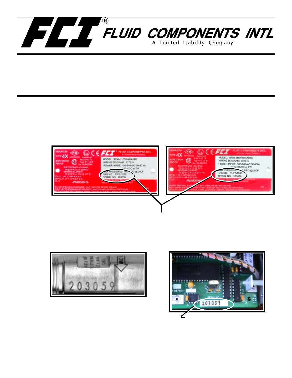
The instrument tags show the model number, tag number (if noted on the customer’s order), serial number along
with other important safety information. Compare this information with the appropriate pipe installation drawings
and calibration sheets to verify the instrument is the correct configuration.
Tag Location - Between Conduit Ports
On Integral or Local Enclosure
If the instrument is a remote configuration, the serial number on the enclosure tags must match. The recommended tag
number on the local enclosure will have an FT in the tag number. The recommended tag number on the remote enclosure
will have an FE in the tag number. (Tags are specified by the customer, “FE/FT” is a recommended naming convention .)
B. Verify the serial numbers on the enclosure(s), flow element and electronics match. The instrument may not work if the
serial numbers are miss-matched. (The remote option has a remote transmitter enclosure (FT) and a local flow
element enclosure (FE). The integral option has one enclosure.)
Flow Element Serial Number
Also Showing Flow Arrow
(Located near the FE enclosure.
It is also on the enclosure tag.)
C. Recommended installation/troubleshooting tools are an open-ended wrench to fit the NPT connection, an open-
ended wrench to fit the flanged fitting nuts and bolts, a small flat blade screw driver for manipulating potentiometers,
both a medium flat blade screwdriver and a medium phillips head screwdriver for tightening connections, 3 mm allen
wrench for CENELEC approved instruments, a measuring tape for proper flow element placement, and a DVM for
Ohm/Voltage measurements.
Doc. No. 06EN003310 Rev.
-
Electronics Serial Number
(Located on the circuit board with the larger I.C.
chips. It is also on the transmitter’s (FT) enclosure tag.)
1 Model ST98 Flowmeter
Tag Location - Top Side of
Remote Enclosure Option
Page 2
FLUID COMPONENTS INTL INSTALLATION, OPERATION AND TROUBLESHOOTING GUIDE
Step 2. Flow Element Installation
Install the flow element, with the flow arrow (shown on Page 1) in the direction of media flow. The element should be in the center line
of the process pipe or rectangular duct. The flow arrow flat area is to be parallel ±2° with the media flow. If the remote transmitter option
is used, the serial number of the flow element is to match the serial number of the electronic enclosure.
Compression fitting option: Metal Ferrules (hard seal) can not be readjusted after the fitting has been tightened. Teflon ferrules
(soft seal) may be readjusted after the fitting has been tightened (but not overtightened).
To insert a compression fitted flow element into the process, measure the inner pipe or duct diameter. Divide the measurement by
2, then add 1 inch (25 mm). Add the pipe wall/fitting thickness to the measurement. Mark the flow element with this measurement. Insert
the element into the process, up to this mark. Tighten the male portion of the fitting into the process. Use appropriate thread sealants.
Tighten the female part of the fitting until the element doesn’t move and there are no leaks. Torque varies per application.
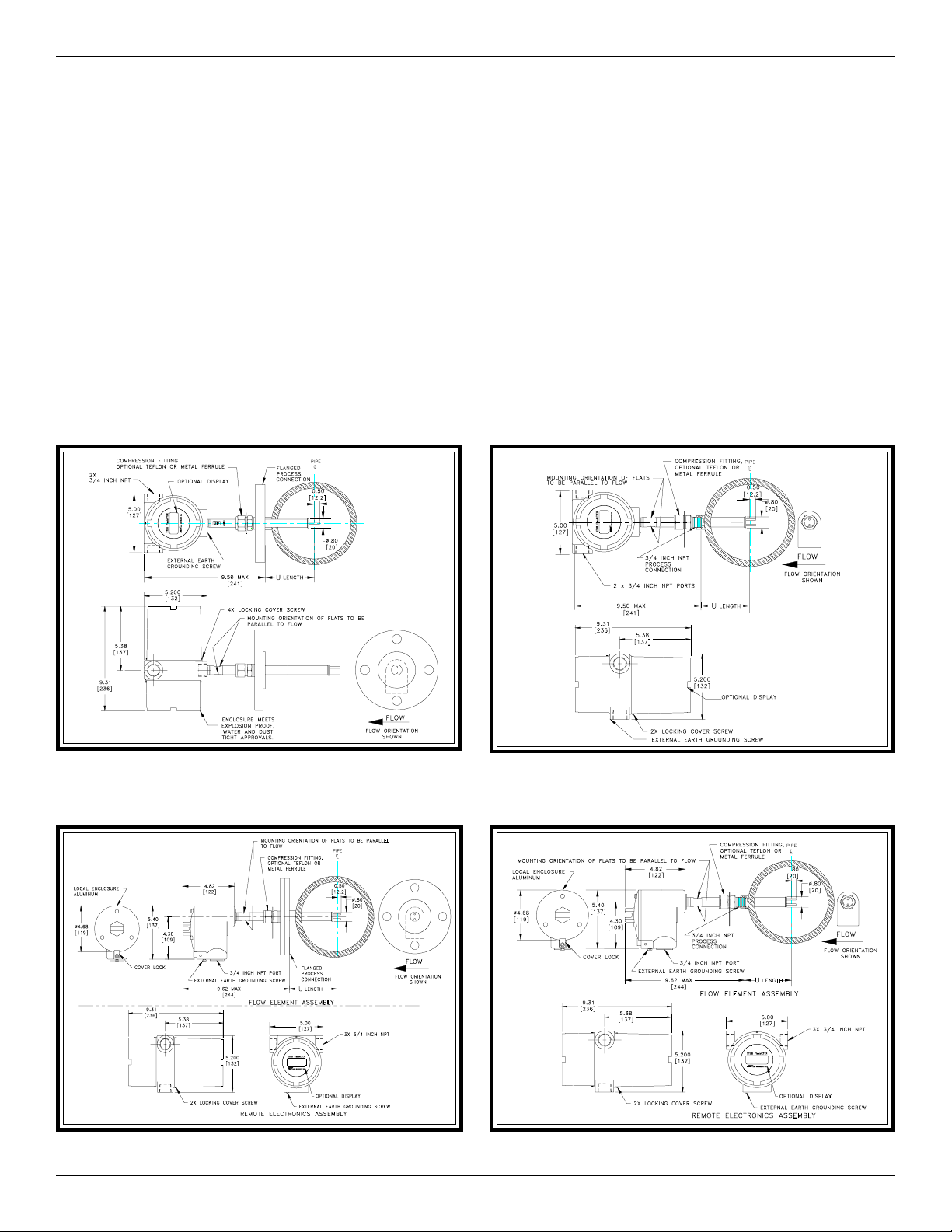
Below are the most common instrument mounting options shown in a typical customer process. See the Installation Section in the
ST98 Manual, Document Number 06EN003291 for more details.
Flanged Integral Instrument (Cylindrical Enclosure) NPT Integral Instrument (Cylindrical Enclosure)
Flanged Remote Instrument (Cylindrical Enclosure) NPT Remote Instrument (Cylindrical Enclosure)
Mode ST98 Flowmeter 2 Doc. No. 06EN003310 Rev. -
Page 3
INSTALLATION, OPERATION AND TROUBLESHOOTING GUIDE FLUID COMPONENTS INTL
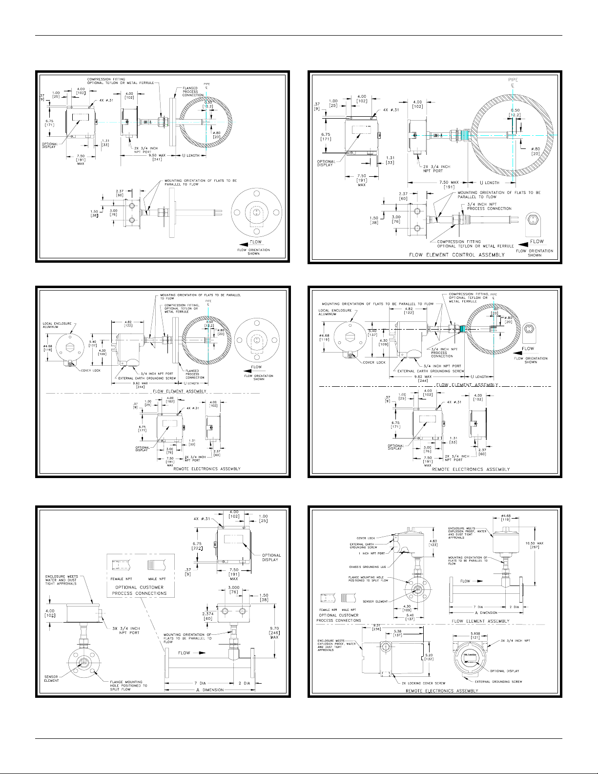
Step 2. Flow Element Installation (Continued)
Flanged Integral Instrument (Box Enclosure) NPT Integral Instrument (Box Enclosure)
Flanged Remote Instrument (Box Enclosure) NPT Remote Instrument (Box Enclosure)
In-Line Integral Instrument (Box Enclosure) In-Line Remote Instrument (Cylindrical Enclosure)
Note: Not shown; In-line Remote Carbon Steel Enclosure or In-Line Integral Aluminum Enclosure.
Doc. No. 06EN003310 Rev.
-
3 Model ST98 Flowmeter
Page 4

FLUID COMPONENTS INTL INSTALLATION, OPERATION AND TROUBLESHOOTING GUIDE
Step 3a. Wiring Preparation (Cylindrical Enclosure Option)
Before the instrument is opened to install the wiring, FCI recommends that the following ESD precautions be observed:
Use a wrist band or heel strap with a 1 megohm resistor connected to ground. If the instrument is in a shop setting there should
be static conductive mats on the work table and floor with a 1 megohm resistor connected to ground. Connect the instrument
to ground. Apply antistatic agents such as Static Free made by Chemtronics (or equivalent) to hand tools to be used on the
instrument. Keep high static producing items away from the instrument such as non-ESD approved plastic, tape and packing
foam.
The above precautions are minimum requirements to be used. The complete use of ESD precautions can be found in the U.S.
Department of Defense Handbook 263.
Open the instrument as shown to wire the instrument:
A. Loosen 1 Allen Screw and unscrew the bottom
cover. The customer termination board is
uncovered.
B. Route conduit to the enclosure. Wire the
termination board per the wiring information
on the next pages.
C. For Remote Installations Only:
Loosen 1 Allen Screw and
unscrew the top cover. Access to
plug TS2 will be required to wire
the instrument per the remote
installation information on the
Page 7.
(Connector TS2)
D. When finished wiring, replace the cover(s) and tighten
the Allen screw(s). See the Installation Section in the
ST98 Manual, Document Number 06EN003291 for more
details.
Step 3b. Wiring Preparation (Box Enclosure Option)
Before the instrument is opened to install the wiring, FCI recommends that the following ESD precautions be observed:
Use a wrist band or heel strap with a 1 megohm resistor connected to ground. If the instrument is in a shop setting there should
be static conductive mats on the work table and floor with a 1 megohm resistor connected to ground. Connect the instrument
to ground. Apply antistatic agents such as Static Free made by Chemtronics (or equivalent) to hand tools to be used on the
instrument. Keep high static producing items away from the instrument such as non-ESD approved plastic, tape and packing
foam.
The above precautions are minimum requirements to be used. The complete use of ESD precautions can be found in the U.S.
Department of Defense Handbook 263.
Open the instrument as shown on the next page to wire the instrument:
Mode ST98 Flowmeter 4 Doc. No. 06EN003310 Rev. -
Page 5

INSTALLATION, OPERATION AND TROUBLESHOOTING GUIDE FLUID COMPONENTS INTL
A
A. Loosen the hold down tabs on the
square (carbon steel) enclosure (3 places)
and open the lid. This gains access
to the instrument’s electronics.
B. Route conduit to the enclosure. Wire the
customer termination board per the wiring
information on the next pages.
C. When finished wiring, close the enclosure and
tighten the hold down tabs. See the Installation
Section in the ST98 Manual, Document
Number 06EN003291 for more details.
(Connector TS2 For Wiring the Remote Option)
Step 4. Wiring the Instrument
Caution:
Only qualified personnel are to wire or test
this instrument. The operator assumes all
responsibilities for safe practices while wiring
or troubleshooting.
Alert:
The instrument contains electrostatic discharge
(ESD) sensitive devices. Use standard ESD
precautions when handling the flow transmitter.
Wiring the Instrument into the Customer Application:
This section describes proper wiring to the transmitter inputs, outputs and interconnection cabling for the optional remote
configuration. For best results route the output wiring through the opposite port from the power wiring. See the table below to
determine the size of wiring to be used versus the length of the wire.
Connection
Inpu t P ow e r 24 24 24 2 0 1 8 16
Sensing Elem ent Cable 24 24 24 24 16 16
(Rem ote Instrum ent)
nalog Output 24 24 24 24 16 16
10 ft. 50 ft. 100 ft. 250 ft. 500 ft. 1000 ft.
(3M) (15M) (76M) (76M) (152M ) (310 M)
M aximum Distance for AWG
Wiring the Instrument’s Analog Signal Output to the Customer Application:
VOLTAGE OUTPUT OPTION
For Voltage Output: 0 - 5 Volts, or 0 - 10 Volts.
Connect the positive output wire to V OUT and the common output wire to OUT COM.
CURRENT OUTPUT OPTION
For Current Output: 4 - 20 mA.
Connect the positive output wire to mA OUT and the common
output wire to OUT COM.
Doc. No. 06EN003310 Rev.
-
5 Model ST98 Flowmeter
Customer Connection Board
Terminal Block TS3 Wiring Diagram
Page 6

FLUID COMPONENTS INTL INSTALLATION, OPERATION AND TROUBLESHOOTING GUIDE
Wiring the Remote Instrument (Option):
Install a shielded, 8 wire cable between the remote
enclosure and the local enclosure as shown.
The Shield wire and the Heater Return wire must
be connected together and inserted into the connector.
The connector is plugged into the connector (TS2)
at the top of the board as shown. Use the schematic
representations of the mechanical assemblies as a wiring
guide.
SENSOR
ELEMENT
RTD GND 1
GND SEN 2
REF SEN 3
ACT SEN 4
REF EXC 5
ACT EXC 6
HTR EXC 7
HTR RTN 8
14 AWG GROUND SAFETY WIRE
LOCAL
ENCLOSURE
TB1
1
2
3
4
5
6
7
8
BOARD ASSY.
P/N 017749
TS2
RTD GND 1
GND SEN 2
REF SEN 3
ACT SEN 4
REF EXC 5
ACT EXC 6
HTR EXC 7
HTR RTN 8
FLOW ELEMENT WIRES
TERMINAL BLOCK
USE 8 CONDUCTOR SHIELDED CABLE ONLY
TOP EDGE OF CIRCUIT BOARD
IN REMOTE ENCLOSURE
CABLE FROM LOCAL
ENCLOSURE
(Shield and HTR RTN are
connected here)
SHIELD
WIRING TO REMOTE
ENCLOSURE
LOCAL
ENCLOSURE
NOTE: The Shield Is Not
Connected To Or In
The Local Enclosure.
SAFETY
RTD
GND
REF
ACT
REF
ACT
HTR
HTR
Wiring the Input Power:
Caution:
FCI recommends placing an ON/OFF switch in line with the power source. When TS1 or TS4 is
connected to the power source, the instrument is ON.
AC or DC power (not both) can be used to operate this instrument. For best results route the output signal wiring through the
opposite port from the power input wiring. See the wiring table on the previous page to determine the size of wiring to be used
versus the length of the wire run to the power source.
Mode ST98 Flowmeter 6 Doc. No. 06EN003310 Rev. -
Page 7

INSTALLATION, OPERATION AND TROUBLESHOOTING GUIDE FLUID COMPONENTS INTL
AC Power Option
Connect AC power (100 - 240 VAC, 50 - 60 Hz) to the instrument (TS1). Connect the AC line wire to AC LINE. Connect the AC
Neutral wire to AC NEUT.
DC Power Option
Connect DC power (22 - 30 VDC) to the instrument (TS4). Connect the positive power wire to D.C. IN +. Connect the negative
return power wire to D.C. IN -. Connect an Earth Ground wire to the EARTH Ground terminal.
CUSTOMER
EARTH GROUND
WIRE
CABLE TIE
FERRITE
BEAD
CABLE TIE
TIE DOWN BRACKET
Earth Ground (Safety)
Connect an earth ground wire to TS1 terminal. The ground wire is customer supplied. The instrument is
supplied with a ferrite bead and cable ties to secure the bead over the wire. A cable tie is provided to tie the wires
(power and ground) to the attachment post for the purpose of wire stabilization.
Wiring the Serial Communications (FC88) Connections (If Needed):
The RJ-12 (P1) connector on the customer connection board
provides RS-232 communication with the user. An FC88
Communicator can be plugged in for periodic re-configuration
and/or diagnostics. See the left hand figure for the location of
P1. This connection is a RJ-12 communication (phone) jack.
Doc. No. 06EN003310 Rev.
-
7 Model ST98 Flowmeter
Page 8

FLUID COMPONENTS INTL INSTALLATION, OPERATION AND TROUBLESHOOTING GUIDE
Step 5. Operation
Before applying power to the instrument, be sure it is connected properly and that the covers are closed.
Apply power to the instrument. Wait 10 minutes for the instrument to stabilize. During this period the instrument may
indicate a high flow condition. After stabilization, the instrument displays an initialization sequence followed by normal
operation information.
Step 6. Troubleshooting
Open the bottom enclosure lid to expose the customer connection board.
Connect the FC88 or computer to the RS-232 Jack (P1).
Set the FC88 communicator or computer to display the T mode (normal operation).
Turn on the NAMUR fault flag, menu X (Press X on the FC88 or computer and follow the menu path).
Compare the fault indication from the T mode with table below. Follow the instructions provided in the table.
Indicated Faults Possible Causes
Nothing displayed on the FC88
or the optional display.
No display on the FC88 no display
on the optional display.
Power is not applied to the instrument. Power is not correctly applied to the customer
connection board. A green LED lights when AC power is applied. It is on the back
side of the customer circuit board behind P1 (it is hard to see). If it is blinking remove
power and contact customer service.
No display on the FC88. There is a display
on the optional LCD display.
No fault indicated. Output mA or Vout
operates correctly.
No fault indicated but the 4-20 mA
(or Voltage) output is not transmitting.
Sensor Error.
OverTemp Head!!
UnderTemp Head!!
Open Heater!!
Shorted Heater!!
If there are still problems with the instrument, see the Troubleshooting Section in the ST98 Manual,
Document 06EN003291. To acquire a manual call FCI Customer Service at 1 (800) 854-1993.
Press [P] [ENTER] on the FC88 to reset . If no response connect it to another ST98 (if
present) to verify operation. Replace the cable between the ST98 and FC88. If no
operation contact customer service.
Verify the NAMUR option is activated [X] [ENTER]. If no fault shown, verify the heater
is on [H] [ENTER]. If no fault is shown, refer to the ST98 Manual, Document 06EN003291.
Go to the Instrument Output Check procedure in the ST98 Manual,
Document Number 06EN003291.
Sensing element wires may be disconnected, shorted or connected to the wrong place.
The active or reference RTD is open or shorted. See the ST98 Manual, Document
Number 06EN003291 for further troubleshooting.
The process temp exceeded the max. temperature rating of the flow element (350°F).
Verify the process temp. If the temp is over 350°F, damage to the sensor element will
occur. Contact customer service.
Process temp exceeded the min. temp of the sensor element. If the temp. is under -50°F,
damage to the flow element occures. Contact customer service.
The sensor element's heater exceeded the max resistance (about 170 ohms) or is
disconnected. This limit includes the cable resistance in remote installations. The heater
fault flag is on when the heater is turned off (using the menu key [H] [ENTER]). Check
wiring and sensor resistance.
The sensor element's heater exceeded the minimum resistance (approximately 90 ohms)
or it is shorted. This limit includes the cable resistance on remote installation. The heater
fault flag comes on in cases when the heater is turned off (using the menu key [H]
[ENTER]). Check the wiring and the sensor resistance.
Notice of Proprietary Rights
This document contains confidential technical data, including trade secrets and proprietary information which are the property of Fluid Components
Intl (FCI). Disclosure of this data to you is expressly conditioned upon your assent that its use is limited to use within your company only (and does
not include manufacture or processing uses). Any other use is strictly prohibited without the prior written consent of FCI.
Visit FCI on the Worldwide Web: www.fluidcomponents.com
1755 La Costa Meadows Drive, San Marcos, California 92069 USA - 760-744-6950 - 800-854-1993 - Fax 760-736-6250
European Office: Persephonestraat 3-01 5047 TT Tilburg The Netherlands - 31 135159989 - Fax 31 135799035
© Copyright 2001 Fluid Components Intl a limited liability company All Rights Reserved
Mode ST98 Flowmeter 8 Doc. No. 06EN003310 Rev. -
 Loading...